1
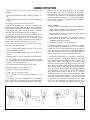
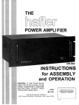
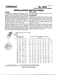
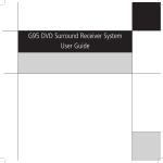
THE
PREAMPLIFIER
DH-110
INSTRUCTIONS
for ASSEMBLY
and OPERATION
LM132
$3.00
Please refer to this serial
number in all communications
regarding this equipment.
THE DAVID HAFLER COMPANY
5910 Crescent Boulevard, Pennsauken, New Jersey 08109
DH-110
SPECIFICATIONS
The numbers in parentheses refer to the paragraph in the IHF specifications manual which defines the test procedure.
PHONO PREAMP SECTION
Rated Output: 3 Wms, 8 Hz-105 kHz
Maximum Output (3.5): 12 Vrms, 20 Hz-20 kHz at recording output
Total Harmonic Distortion: Less than 0.0006% @ 1 kHz, 3 Vrms
Frequency Response (3.13): +0, -0.25 dB, 20 Hz-20 kHz
RIAA Equalization Accuracy: +0, -0.1 dB, 30 Hz-15 kHz
Full Power Bandwidth: -6 dB, 4 Hz-210 kHz
Sensitivity (3.7): 12.5 millivolts
Maximum Input Signal @ 1 kHz (3.8): 300 millivolts; [3 V @ 20 kHz]
Gain: 34 dB @ 1 kHz
Input Impedance: 47,000 ohms in parallel with 30 pF; user adjustable.
Plug-in capacitors are installed to increase this
to 150 pF on Phono 1; 250 pF on Phono 2
Signal to Noise, weighted (3.12): 87 dB
Slew Rate: 12 volts per microsecond
LINE AMPLIFIER SECTION
Rated Output: 3 Vrms, 4 Hz-210 kHz
Maximum Output (3.5): 14 Vrms, 20 Hz-20 kHz
Total Harmonic Distortion (3.4): Less than 0.001%, 20 Hz-20 kHz
Frequency Response (3.13): +0, -0.1 dB, 20 Hz-20 kHz
Full Power Bandwidth: -6 dB, 2 Hz-420 kHz
Sensitivity (3.7): 50 millivolts
Maximum Input Signal @ 1 kHz (3.8): 14 Vrms; volume control @ -20 dB
Gain: 20 dB ± 1 d B
Input Impedance: Greater than 25,000 ohms
Signal to Noise, weighted (3.12): 90 dB
Slew Rate: 12 volts per microsecond
Rise Time: 2.5 microseconds maximum, Phono in / Line out, 10 Vp-p,
1 kHz square wave; load is 10,000 ohms in parallel with 10 nF
Crosstalk (3.14): down 72 dB, any input to any output
Separation (4.2): greater than 82 dB @ 1 kHz; greater than 52 dB @ 20 kHz
Gain Tracking Error (4.4): less than 0.5 dB
Maximum Output Noise: less than 350 microvolts, wideband
less than 95 microvolts, ‘A’ weighted
[with 1 Kohm input termination, volume full CW]
Bass Control: 217 dB @ 20 Hz, moving inflection, variable turnover
Treble Control: ±17 dB @ 20 kHz, shelving @ 5 kHz, fixed turnover
Filter Response: -3 dB @ 25 Hz; -6 dB @ 15 Hz; -12 dB @ 8.2 Hz; -25 dB @ 3 Hz
Filter Cutoff (3.13.2.2.1; 3.13.2.2.2): 25 Hz; -12 dB/octave
GENERAL SPECIFICATIONS
Semiconductors: 30 transistors, 3 ICs, 12 diodes, 2 LEDs
Inputs: 2 Phono, Tuner, Compact Disc or Video, 2 Tape recorders, EPL
Outputs: 2 Tape (buffered), 2 Line, EPL, Headphone Jack
Controls: Volume, Balance, Bass, Treble, Input Selector, Phono l/2 Selector,
Monitor Selector, Mono-Stereo, Filter, External Processor Loop,
Tone Control Engage, Power
Intermodulation Distortion: Both SMPTE and CCIF IMD at operating
levels from phono input to line output are below the
residual of currently available instrumentation
AC Supply Voltage: 100-130 and 200-260 VAC, 50/60 Hz
Power Consumption: 3.5 watts
AC Convenience Outlets: 3 switched, 5 amp continuous, 72 amp surge
1 unswitched,
5 amp continuous
Size: 17” wide x 3” high x 8½” deep
19” rack mounting accessories included
Shipping Weight: 12.5 lbs.
Net Weight: 10 lbs.
2
© Copyright 1985. All rights reserved.
INTRODUCTION
Your preamplifier is the control center of your music
system, acting as an interface between the sound
sources-record players, tape recorders, FM and Video
tuners-and the power amplifier which drives the
loudspeakers. As the focal point of your system, it should
be attractive and easy to use, versatile and yet functionally
unobtrusive. It should contribute a minimum of noise or
distortion while providing signal amplification, control of
the signal level, and applicable modification of the frequency response.
The DH-110 achieves all these objectives with great
versatility, providing for two record players with magnetic
cartridges, two tape recorders, a tuner, and an additional stereo
input for a compact (digital audio) disc player or video audio. It
also includes inputs and outputs for an external signal processor
such as a graphic equalizer, time delay device, or noise
reduction unit. The performance of the DH-110 is exemplary,
and its assembly from an array of discrete components of
exceptional quality should ensure reliability and longevity of its
capabilities.
Exceedingly low noise and distortion is a hallmark of the
DH-110. Noise is essentially inaudible in the absence of a
signal, and distortion of all types, both steady state and
transient, is at or below the threshold of the finest measurement capabilities. These excellent characteristics are
maintained far outside the customary 20 Hz to 20 kHz
band, and signals well beyond that are handled without the
need to restrict bandwidth.
Precise interchannel balance at all frequencies is maintained with close tolerance components, and RIAA phono
equalization is engineered to very narrow limits, maintaining accurate phase relationships and correct spatial
perspectives, as well as exceptional unit-to-unit consistency. The tone controls, which can provide contouring of
response for individual needs when switched in, are normally isolated from the circuit for ruler-flat response.
The components in the DH-110 have been selected for
their superb audio performance as well as for their reliability. They have been incorporated in the unique Hafler fully
complementary symmetry push-pull circuit in a carefully
designed circuit board layout which reduces crosstalk and
maintains separation for a synergistic audio result that
defies comparison, regardless of cost.
Those who have chosen to build the kit will find that its
step by step instructions will ensure a properly working
unit even for the novice builder. A substantial amount of
preassembly has enabled us to check out each kit in nearly
every aspect of performance, and makes the DH-110 a particularly fast, easy and enjoyable construction project,
which you will likely complete in one evening.
We suggest that you read the installation and operation
sections of this manual carefully, even though much may
be familiar to you. There are some subtle and significant
points which may be new, and their proper appreciation
will enable maximum satisfaction with your DH-110. We
wish you to have the very best in sound.
CONTENTS
Installation . . . . . . . . . . . . . . . . . . . . . . . . . .
Page 4
.5
Operation . . . . . . . . . . . . . . . . . . . . . . . . . . . . . . .
Assembly Instructions. . . . . . . . . . . . . . . . . . . . .7
.9
Building the Kit . . . . . . . . . . . . . . . . . . . . . . . . . .
PC-14 Diagrams . . . . . . . . . . . . . . . . . . . . . . . . .12
If a Problem Arises . . . . . . . . . . . . . . . . . . . . . . .15
Overseas AC Line Connections . . . . . . . . . . .15
Additional Information . . . . . . . . . . . . . . . . . .
.16
Functional Block Diagram . . . . . . . . . . . . . . . .16
Component Values . . . . . . . . . . . . . . . . . . . . . .19
Schematic Diagram . . . . . . . . . . . . . . . . . . . . . .20
Kit Parts List . . . . . . . . . . . . . . . . . . . . . . . . . . .
.22
Service and Warranty . . . . . . . . . . . . . . . . . . . .23
Pictorial Diagram . . . . . . . . . . . . . . . . . . . . . Insert
3
The DH-110 is provided with accessory Rack Mount end
caps in addition to the standard end caps installed on the
unit. These accessory caps extend the width of the front
panel to that of a standard 19” rack, with appropriate
mounting holes. Installation instructions are detailed later
in this manual under Additional Information.
POWER CONNECTIONS
As assembled, units are normally wired for 120 VAC,
50-60 Hz, as in the USA, unless they are specially identified on the carton. In the Additional Information section
you will find diagrams of alternate wiring of the power
transformer to conform to other line voltages.
The power regulation of the DH-110 will provide full performance with line voltages which may vary substantially
from the standard. Units wired for 120 volts, for instance,
will work properly with line voltages between 95 and 130
volts.
Accessory AC outlets are provided on the back panel for
other equipment. One unswitched outlet is provided for a
turntable or tape recorder whose mechanical system may
require disengagement through its own power switch.
Most units, including power amplifiers, tuners, and many
tape recorders and record players, may be connected to
the switched outlets for convenient remote switching from
the preamp’s front panel. The DH-110 power switch has
been tested to provide adequate capacity for any Hafler
power amplifier and typical related equipment. You should
heed the maximum power rating printed on the back panel
of the unit.
INPUTS-Magnetic
Phono
There are two pairs of phono inputs, identified as Phono
1 and Phono 2. These are independent, and thus they may
have different capacitive termination for differing cartridge requirements. As assembled, Phono 1 is provided
with a compensation capacitor of 120 picofarads, and
Phono 2 is provided with 220 picofarads. One of these values will accommodate most ‘Moving magnet’ cartridges.
These have output levels intended for normal phono inputs (0.5 millivolts per centimeter or higher) and are the
most popular. Some high output ‘moving coil’ design cartridges are not sensitive to capacitive loading, so they may
be used with either input.
Though some phono cartridges are comparatively free
of loading sensitivity, if the cartridge manufacturer
specifies the proper load capacitance (which is the sum of
the preamp’s internal capacitance, and the cables you use,
as well as the above described capacitor), the most accurate sound will be obtained by following that recommendation. If you have chosen the DH-110 for its sonic attributes,
you will be more likely than most to be aware of these differences, and will want proper cartridge termination.
4
The Additional Information section of this manual details the determination of the loading capacitor for a
specified cartridge load. It also describes how the resistive
load of the phono inputs may be changed, if needed, from
the standard 47K ohms.
Moving coil design cartridges often require an auxiliary
step-up transformer or pre-preamplifier (head amplifier)
because of their low output signal. The DH-110 has provision for internal addition of an accessory Hafler prepreamplifer which you or your dealer can install at any
time. This enables the Phono 1 input to accommodate such
cartridges directly. The Additional Information describes
its installation.
Adjacent to the Phono 1 input sockets are two Ground
terminals on the back panel. These thumbscrews provide
for connection of separate ground wires often provided on
turntables, or as part of their audio cables. This ‘chassis
ground’ may sometimes reduce the hum level of a system
when it is connected to an earth ground, such as a cold
water pipe, or the ground wire of 3-wire house wiring.
However, the need for such connection varies with individual situations. After the system is operative, using a
phono source, experiment with and without an earth
ground to determine which provides the lowest hum, and
use that.
IMPUTS-Tuner,
CD/Video
These are high level (line-50 millivolts or more) signals
from FM, AM or TV tuners, or compact digital audio disc,
video disc, or VCR players. These inputs are grounded at the
selector switch when they are not chosen for listening. The input
impedance is approximately 33K ohms.
INPUTS-Tape 1, Tape 2
These are at line level and impedance. They connect to
Tape Play outputs on the tape deck. They are not grounded
when unused, since they can be connected by either the
main selector switch or the Tape Monitor switch. They are
terminated with 1 megohm resistors to avoid a possible
switching transient.
RECORDING
OUTPUTS
These connect to the Line Inputs of tape decks. The two
pairs of outputs are wired in parallel. Thus two tape recorders receive identical signals. These outputs are buffered
with a series resistor, and have an output impedance of
1.5K ohms. To provide full specification performance, the
total tape recorder load should not be lower than 10K ohms
(i.e. two 20k ohm recorder inputs on each channel).
Because it is possible that a preamplifier’s overall performance may be adversely affected by rectification ef-
fects that can result from unpowered electronic circuits in
the tape decks when they are connected to the Recording
Outputs, it is recommended that tape recorders be
switched on when the preamplifier is in use. This is a
commonly overlooked cause of less-than-ideal
preamplifier performance.
Signals at these outputs are at line input level (phono
signals are first amplified and equalized). These outputs
are unaffected by external processing circuits, or by the
DH-110’s Mono, Filter, Tone or Volume controls. Only signals indicated by the Selector switch are available, including the other tape input, so tape copying is provided using
either recorder as a source.
LINE OUTPUTS
Two pairs of outputs are provided for your power
amplifier connection. The set labelled ‘Via Phones’ is
suggested for those who regularly listen through headphones as an alternative. These are wired so that when
headphones are plugged in, the signal is disconnected from
the power amplifier. Two purposes are thus served. Since
many headphones require fairly high volume control settings, you avoid inadvertent high signal levels to your
speakers. And a power amplifier which is turned off cannot degrade the quality of signal to the headphones-
which is otherwise a possibility. We recommend that you
turn off power amplifiers before connecting headphones,
or that they be plugged in before the system is switched on,
as a precaution.
The Direct outputs provide conventional signal levels
independent of the headphone circuit. If headphones are
plugged in, the level of the Direct output will be greatly
reduced. These outputs should not be used when headphone use is anticipated.
The performance specifications will be met so long as
the input impedance of the power amplifier is 10K ohms or
higher, and the cable capacitance is less than 1Onf. This is
no problem with typical interconnecting cables up to 10
feet. If you are planning to use very long cables between
preamp and power amplifier, special low capacitance cable
can be obtained.
EXTERNAL PROCESSING LOOP
‘Send’ is an output at line level for the purpose of driving
an external signal processor such as an equalizer, time
delay, or noise reduction unit. Like the recording outputs,
the load impedance should not be less than 10K ohms. The
EPL ‘Return’ input impedance is 33K ohms, and should
also be at line level. The EPL Return can also function as
an additional high level input, switched from the front
panel.
OPERATION
When you turn on the DH-110, power is also applied to
duplicated by selecting the playback tape recorder on the
the switched AC outlets on the back panel. One of the red
Selector switch, and recording on the second machine.
LEDs on the front panel will light, indicating that the
PHONO AMPLIFIER
preamp is functioning. Typically, it will be the left-most
The button in the lower left of the front panel selects
LED, indicating that the Selector switch is determining
either Phono 1 (in the OUT position) or Phono 2. The
the signal source. At turn-off, it is normal for the LED to
switch may be operated to compare two cartridges while
fade slowly as the operating voltages decline.
music is playing, but if them is no cartridge connected to
one input, noise or RF interference may cause a small auDELAYED TURN-ON
dible transient. The phono signal is accurately RIAA
An internal muting circuit prevents the voltage tranequalized and amplified 34dB (at 1kHz), then passed to the
sients which may occur at turn-on or turn-off from causing
Selector switch at line level.
annoying noises, blown fuses or damaged loudspeakers.
At turn-on, the Line Outputs (but not the Recording
Outputs or EPL Send output) will be held near ground potential for a few seconds until the internal voltages have
stabilized, and the unit is ready for operation. Only a faint
output can be heard during this time.
At turn-off, whether by operating the preamp’s power
switch, or as a result of external AC failure (a ‘brown-out’,
pulled plug, or blown house fuse), the line output will be
instantaneously lowered. Following power interruption,
the muting circuit will initiate a few seconds delay before
allowing full signal at the line outputs.
SIGNAL SELECTION
Your choice of signal sources is usually indicated by the
Selector Switch, identified by the adjacent lighted LED.
This switch passes line level signals direct to the Recording Outputs and to the EPL Send output as well as to the
Mono switch and subsequent line amp controls. Either or
both tape recorders may record this source. Tapes may be
MONITOR SWITCH
To facilitate tape recording with tape decks which provide an independent monitoring facility, the DH-110 provides this second selection function. When it is OFF, the
regular Selector switch determines what signals are heard.
When the Monitor switch is turned to either Tape 1 or Tape
2, the line amplifier is quietly disconnected from the signal
being recorded, and is connected to the tape playback instead. This enables direct comparison of the signal source
with the taped replica, without affecting the recording process. Tape decks which do not provide separate record and
playback heads are not able to utilize this comparison.
Note: Do not turn the Monitor switch to Tape 1 if the
Selector is also set to Tape 1. Likewise avoid simultaneous
Tape 2 settings on both switches. Feedback will occur, and
there is a possibility of damage.
When the Monitor switch is not in the OFF position, the
LED at the Monitor switch will light, in place of the Selector LED, reminding you that tape playback has been
selected.
5
The following controls affect all signals which are
heard through speakers or headphones. They have
no effect on the signals to the recording outputs.
MONO SWITCH
When this button is IN, left and right channel information is combined, and the composite signal is fed to both
left and right outputs. In this mode the sound image should
appear to be centrally located between the loudspeakers.
Critical listeners sometimes choose the mono mode for
system evaluation, for it enables you to isolate system response from the complexity of stereo effects. This switch
is also useful when listening to monophonic program material. It cancels the unwanted vertical phonograph modulations which are heard as noise from monaural records.
FILTER SWITCH
This is a low frequency cutoff to remove much of the
signal below 25 Hz, such as noise, turntable rumble, or
loudspeaker-turntable feedback. Even in cases where the
speakers may have little response at these frequencies,
this filter can be useful. Very low frequencies can modulate
audible midband signals, so eliminating this interference
can improve overall clarity.
Note: The Filter button should be OUT when the DH-110
is turned ON to avoid a switching transient during the first
minute of operation. If it is IN at turn-on, wait one minute
before releasing it.
EPL SWITCH
This is the External Processor Loop. Engaging this
switch enables a signal processing device to be inserted in
the preamplifier signal path. Such devices include equalizers, time delays or ambience simulators, expanders, compressors, and noise reduction systems. Since the switch
permits bypassing the processor loop, an unpowered device in the EPL circuit will not deteriorate the DH-110 performance, as might be the case with switched-off tape
decks in the Record Outputs. The EPL switch can also
function as an additional input selection.
TONE SWITCH
Until this button is depressed, all tone control circuitry
is completely removed from the signal path. Activating
this button may cause a slight change in the tonal balance
even when both Bass and Treble controls are in their median (detent) position. Potentiometer tolerances preclude
coincident mechanical and electrical centering. The tone
control circuitry limits, to an extent, the total bandpass of
the DH-110.
Operation of the Tone button will be silent if it is depressed
in a natural, deliberate manner. Rapid switching may generate small transient pulses.
BALANCE CONTROL
This adjusts the proportion of left and right channel signals to the Line outputs. In its detented center position the
channels will be matched to ±0.1 dB. Only the Left signal
will be heard with the control fully counterclockwise, and
only the Right signal at the other extreme.
The ideal situation would find symmetry in room acoustics and in the electronics, but this realization is rare.
Stereo reproduction is, at best, a splendid illusion, and the
function of the Balance control is to optimize this illusion
in the listening space. Sound wave reflections from walls,
furniture and people can unbalance the stereo ‘stage’. With
judicious application of the balance control, much of the
attendant distortion of stereo imaging can be overcome.
With the preamplifier in the Mono mode, it will be easier to
use the Balance control to centrally position the apparent
sound source. This mono setting can then serve as a useful
reference point, though the appropriate balance setting
may vary from recording to recording in the stereo mode.
Our point is that Balance and Tone controls are intended
to facilitate the most satisfying sound to the listener; it is
appropriate that they be used to this end.
BASS and TREBLE CONTROLS
The Tone Switch must be IN for these controls to be effective. At full rotation, each control provides about 17 dB
of boost (clockwise), or cut (counterclockwise) at the frequency extremes from the center ‘flat’ (detent) position.
The Bass control has a variable inflection, or ‘hinge’
point so that only the very low frequencies are affected by
small amounts of rotation either side of center. This facilitates low frequency corrections without noticeably altering the musical balance, but speakers with diminished low
frequency response will not reflect small angular movements from the detent. As the control is turned further,
frequencies closer to 500 Hz are affected, so the effect is
more apparent.
The Treble control has a fixed ‘hinge’ point at 1kHz and
has a ‘shelving’ action above 5kHz. This affords proper
correction without irritation from excessive boost at the
extreme.
VOLUME CONTROL
This step action control was selected for its very accurate tracking between channels, and for its low contact distortion. Clockwise from the 12 o’clock position it increases
in increments of roughly 1 dB. From 12 o’clock counterclockwise it progresses in increasing increments to full
attenuation.
HEADPHONE JACK
A 3-circuit shorting jack is connected so that the tip is
the left channel, in series with one set of line outputs, so
that the power amplifier is automatically disconnected
when the headphones are plugged in. We recommend that
you turn off the power amplifier before you connect headphones, or that they be plugged in before the preamplifier
is turned on, to guard against needless transients. Be sure
the volume is turned down before headphones are disconnected.
There are three basic rules for success in electronic kit
building:
1: Read the instructions carefully, and follow them in order.
2. Make secure solder connections which are bright and
smooth.
3. Check your work carefully after each step.
The DH-110 preamplifier is a versatile component with
sophisticated circuitry which has been made remarkably
easy to build by individuals with many years of experience
in the design and engineering of the finest performing
audio kits, and in the preparation of their manuals.
Kit building should be fun, and we am certain you will
find this to be so. Fatigue increases the risk of error, so
take a break rather than push to early completion. There
are relatively few separate components in this design, to
make it easy to pack everything away, if need be.
Your work area should have good lighting and the proper
tools. The tools should include:
1. A 40 to 60 watt pencil soldering iron with a 3/16" or smaller tip which reaches 700°F
2. 60/40 (60% tin) ROSIN CORE solder, l/16” diameter or
smaller.
3. A damp sponge or cloth to wipe the hot tip of the iron.
4. A wire stripping tool for removing insulation. This can
be a single-edge razor blade, but inexpensive stripping
tools are safer, faster and easier.
5. A medium-blade screwdriver (about l/4” wide).
6. Needle-nose pliers (a long, narrow tip).
7. Diagonal or side-cutting small pliers.
8. Large “gas” or “slip-joint” pliers.
9. A l/4” “Spin-tite” nut driver may be helpful, but is not
necessary.
A soldering “gun” is not recommended. The unfamiliar
user is more likely to damage the etched circuit boards
with its higher heat potential and unbalanced weight. Also,
because he may not wait long enough for it to reach operating temperature each time it is switched on, poor solder
connections are more likely. Pencil irons are much lighter
and easier to use, and there is no waiting time when solder
connections follow in sequence, as in kit building. Make
sure you have a holder for it, though, and always unplug it
when you take a break.
Proper Soldering
There are four steps to make a good solder connection:
1. Make a good mechanical connection to hold the wire in
position while heat and solder is applied.
2 . Heat the junction of the wire and lug, or eyelet, with the
bright, shiny tip of the iron.
3. After heating for a couple of seconds, apply solder to
the junction. It should melt immediately and flow
smoothly around both surfaces.
4. Allow the connection to cool undisturbed.
Remember that the connection is made by the solder,
not by mechanically attaching the wire to the terminal.
Usually the wire is looped through the lug and crimped in
place, but some prefer to just place it through the hole and
rely on the stiffness of the wire to hold it while soldering.
Eyelet connections, of course, are handled this way.
Good solder connections are essential for trouble-free,
noise-free operation. A good solder joint does not require
much solder around the conductors. Never “butter” partially melted solder on the joint, as it is useless. A good
connection looks smooth and bright because the solder
flows into every crevice when the parts am hot enough.
The iron must have a bright, shiny tip to transfer heat easily to the junction. That’s why the damp sponge should be
used frequently to wipe the tip, and occasionally you must
add a small amount of solder to the tip, too. If a connection
is difficult to heat, “wet” the tip with a small blob of solder
to provide a bigger contact surface to the joint. Once the
solder flows around the conductors, any movement must
be avoided for a few seconds to allow a good bond. When
cool, check the connection by wiggling the wire. If in
doubt, or if the connection is not shiny, m-heat the joint.
Excess solder may be removed from a connection by heating it and allowing the solder to flow onto the iron, which is
then wiped on the sponge.
ALL SOLDER USED MUST BE ROSIN CORE
Never use acid core solder or any separate flux in electronic work. Silver solder is also not suitable. If in doubt
about unmarked solder, always obtain a fresh supply of
rosin core solder. We recommend 60/40 for easiest use. Do
not confuse it with 40/60, which is harder to melt.
The general procedure is to use a hot iron for a short time
to heat a connection, then add solder with the iron still in
contact. Remove the solderonce it flows, and then remove
the iron. A cooler iron applied for a longer time is more
likely to damage components, or lift the copper circuit pattern from the boards. A break in the etched circuit can be
mended by simply soldering a small piece of wire across it.
Do not allow much build-up of solder on the tip of the iron,
or it may fall onto adjacent circuitry and cause a short circuit.
When soldering to an eyelet or hole on the board, insert
the wire from the components side, and apply the iron to
the bottom, leaving some bare wire exposed so that you
can see that the eyelet is then filled with solder for a secure
bond. A round wooden toothpick is suggested so that you
can heat and clear an eyelet of solder if it hinders your inserting the wire. Some builders prefer to clear every eyelet
first with a touch of the iron and toothpick. Others connect
the lead by bringing it up to the center of the eyelet on top
of the board, applying the iron from the bottom of the
board, and pushing the lead in as the solder in the eyelet
melts. If the wire has first been “tinned,” usually no additional solder is necessary, but it is a good practice to push
the wire through, and then back it up a bit, to be sure solder
fills the eyelet. On the bottom of the board, make certain a
bright, shiny flow is evident from the wire onto the circuit
pattern on the board.
“Tinning” refers to the process of applying a light coating of solder to the bared wire end. This keeps all the
strands secured, and also makes a good connection easier.
Simply touch the wire with the iron for a couple seconds,
and apply solder. Allow the excess to flow away onto the
iron. When properly done, the wire is uniformly bright,
and no larger than before. The hookup wire supplied with
this kit does not normally need tinning, for it is pre-tinned.
Wiring the Kit
If any components are unfamiliar to you, checking the
pictorial diagram should quickly identify them. Or, the
quantities, and the process of elimination as you check the
parts list, will help. The pictorial diagram is necessarily
distorted to some extent for clarity, so that you can trace
every wire in a single overall view for verification as you
work.
To “prepare” a wire means to cut the designated length
from the length of that color, and strip about l/4” of insulation from each end. The wire supplied in the kit is #18 and
#22, so you can set adjustable wire-strippers accordingly.
The transformer leads are #18, and the line cord is #16. Be
careful that you do not nick the wire when you strip it (that
can happen more easily if you do not use wire strippers) for
that weakens it. The wire supplied in this kit is “bonded
stranded,” which provides exceptional flexibility with resistance to breakage for easier use.
Whenever a connection is to be soldered, the instructions will so state, or indicate by the symbol (S). If more
than one wire is to be soldered to the same point, they will
be indicated by (S-2), (S-3), etc. If soldering is not called
for, other connections have yet to be made to that terminal. They would be more difficult if the connection was already soldered. Every connection in the kit will be soldered when it is complete. After soldering a connection, it
is best to clip off any excess lead length to minimize the
possibility of a short circuit, and for neatness.
Be sure that uninsulated wires cannot touch adjacent
terminals or the chassis metalwork.
When the instructions call for twisting two or three
wires together, the length of wire indicated anticipates a
fairly tight, uniform twist by hand, of three full turns every
two inches. If you find the wires too short, loosening the
twist will gain some needed length.
Take the time to be accurate and neat, and you can be
sure that your completed preamplifier will meet the performance of a factory assembled unit, and can continue to
perform properly for years to come. Check your work, and
make sure the entire step has been completed before placing a check mark in the space provided, and continuing on
to the next step.
BUILDING THE KIT
Partial mechanical assembly of the kit provides protection for major components during shipment. Most of the
hardware thus used is included in the quantities listed in
the parts list. The exception is that used to install the rear
mounting bracket on the PC-14, as this is considered an integral assembly. Only the two screws securing the bracket
to the side pieces need be removed, along with the
hardware securing the front sub-panel. Dismount the
power transformer and remove the side pieces.
A “set” of hardware includes a screw and a KEP nut
with attached lockwasher. Always install the lockwasher
side first. Screws are always inserted from the outside of
the chassis unless otherwise specified. #4 hardware is
smaller in diameter than #6. To separate #4 nuts from the
#6s, use a long #4 screw to test.
We suggest you check off the parts as you unpack the
kit, and separate them in an egg carton for convenience.
1 0 The flanges of the front sub-panel bend towards the
inside of the preamp. Select the U-shaped headphone jack mounting bracket and 2 sets of #4
hardware. Install the mounting bracket on the outside of the front panel, in front of the rectangular
hole in the lower right comer.
2 0 Select the headphone jack, its washer and nut.
Install it through the front panel with the single lug at
the bottom. The washer goes outside the bracket,
secured by the nut.
3 0 Prepare a 2” black wire. Connect one end to the
lower forward lug of the headphone jack. (S). Place
this wire through the panel.
4 0 Prepare a 14½” green wire, but strip 3/8” of insulation
from one end. Prepare a 14½” red wire. Prepare a 14½”
black wire. Start with the red wire ¼ ” longer than the
longer bare end of the green wire, and the black wire ½”
shorter than the green wire. Twist these 3 wires together
uniformly throughout their length. Make about 3 complete twists every two inches. On the rear of the phone
jack 8 numbered positions identify the 6 lugs in a counterclockwise rotation, with the #2 lug at the bottom (in line
with the front lug), and the #6 lug at the top. Insert the
longer bared end of the green wire through the #8 lug and
connect it to lug #7. Solder both lugs. Connect the red
wire to lug #6. (S).
5 @ Prepare another 14%” green wire with 3/8”stripped from
one end. Prepare one end of a 14½” black wire. Do not
strip the other end. Prepare another 14½” red wire. Start
with the longer green wire end ¼” longer than the red
wire, and the bare end of the black wire ½” shorter than
the red wire. Twist these together as before. Insert the
longer end of the green wire through lug #3 of the phone
jack and connect it to lug #4. Solder both lugs. Connect
the red wire to lug #2. (S).
6 0 Select the power switch and two #4 screws. Install
the switch above the headphone jack so that the
body of the switch is offset to the outer edge of the
panel.
7 0 Select the main PC-14 circuit board assembly, with
the fuse in place, and the rear bracket installed, and
a rubber grommet in the bracket. Select the 6 larger
nuts and washers for securing the controls to the
front sub-panel. The two largest sets are used for the
selector switches; the volume control is the smallest
size, next to the power switch; the 3 other sets go on
the 3 central control shafts. Be sure all the locating
lugs on the controls engage the holes in the panel before securing the hardware. The wires from the
phone jack go under the board. Push the ends of the
wires through the grommet.
8 0 Select the small circuit board assembly PC-13 and
two #4 screws. With the circuit board uppermost,
position the assembly at the top of the large front
panel opening so that the sockets on the board align
with the pins from below, and plug the board downward onto the pins. Make sure each pin is properly
engaged. Secure the assembly with screws through
the panel.
Set the front panel aside, and select the PC-12 circuit board.
The front of the board marks the component locations, and “J”
designations. Most components mount on the front. Always
install them tight against the board, and solder each lead on the
back (circuit) side. Then cut off all excess leads.
9 0 Select the two 22,100 ohm resistors (red, red,
brown, red) and install them at locations R50 and
R150.
10 0 Select the two 1,100 ohm resistors (brown, brown,
black, brown) and install them at R21 and R121.
11 0 Install the four 1 megohm resistors (brown, black,
black, yellow) at locations R22, R23, R122 and
R123.
12 0 Select the two 4-pin molded sockets. These are to be
installed at locations J26 and 5126 on the front of the
board, with the pins through the upper row of holes
(arrow) at each location. The lower row of holes
provides access from the rear of the board for plug-in
capacitors. lb assure correct alignment of the socket, insert a capacitor lead from the rear into holes E,
F, G and H to engage the sockets while you solder
the pins, and then remove the capacitors. Be sure
solder flows freely around each mounting pin for a
good connection. Sometimes these pins do not accept solder easily.
13 0 The proper way to install the 24 phono input sockets
is to first insert a phono plug (on the end of one of the
audio connecting cables supplied in the kit) so that
the center contact will not be deformed in the
mounting process. Adjacent to the center hole for
9
each socket, the board is marked to indicate the side of
the hole on which the center mounting tab should be
positioned, so that it will be soldered to the widest part of
the circuitry on the back side. Leave the phono plug in the
socket while bending and soldering is completed. If you
do not bend the center tab quite flat against the board, it is
easier for solder to flow under the tab for a good connection. Solder both outer socket lugs first (they need not be
bent over), and then the center tab on each socket. At J9
be careful that a solder bridge is not made between the
center contact and the adjacent circuit track. Be sure
holes Q and S are not filled with solder when installing
sockets J 11 and J 1 1 1. A wooden toothpick will keep
them open.
14 0 Select the two right angle 15-pin plugs, and install
their shorter pins at locations J22 and J24 at the top
of the board, so that the bent pins point toward the
upper edge. Be sure these sockets are tight against
the board, and make certain that every pin connection is properly soldered. Examine each connection
closely to make sure there are no solder bridges
between the tracks.
15 0 Prepare a 1” piece of green wire, and form it into a ½”
wide “U”. This wire connects on the back of the
board between holes A and B. Allow this wire to sit a
bit above the board, as it is a jumper which you may
wish to remove at some future date, if you install a
pre-preamplifier for a moving coil cartridge. After
soldering be sure you cut off any excess wire on the
front, so it cannot short to the input socket.
16 0 Prepare a 1” piece of red wire, and form it into a “U”
as before. Connect it in like manner to holes C and D
on the back of the board.
17 0 Select the two 10,000 pF capacitors and install them
on the front of the board at locations C1 and C101.
18 0 Select the 2 long bright screws, the 2 lockwashers,
and two of the spacers. Place a lockwasher over
each screw first, and insert the screw from the back
(circuit side) of the board into one of the mounting
holes next to the rear jumpers. Add a spacer on the
components side, and tighten it. Set the completed
board assembly aside.
19 0 Select the back panel, the AC line cord, and the plastic strain relief. Separate the two conductors at the
end of the cord for 2”. Cut 3/4" off of one conductor.
Strip both ends the usual ¼", and tin the strands to
secure them. Six inches from the longer end make a
sharp V in the cord by bending it back on itself.
Install the strain relief as shown in the drawing. The
small end of the strain relief is nearest the stripped
ends. Crimp the two halves of the strain relief
together around the cord with heavy pliers to partially form it before insertion into the back panel.
10
Then grip the larger portion of the strain relief with
the tips of the pliers, squeeze it tightly, and insert the
end of the cord and the strain relief through the panel
hole from the outside. Note that the hole has a flat on
one side, and the strain relief is installed so that the
cord is horizontal.
This is the most difficult step in the kit. Patience, and
a friend’s help, if available, will make this job easier.
Safety requirements dictate that this be a tight fit.
Some persons might find it helpful to bolt on a side
piece (with the flanges out) to add rigidity to the
back panel, as well as a support to press against the
back panel while you squeeze the strain relief and
pull the line cord through. The fixture snaps into position when it is fully inserted. Remove the side piece
if you attached it.
20 0 Select the power transformer and 2 sets of #6
hardware. Install the transformer next to the line
cord so that the leads are in the lower comer below
the strain relief.
21 0 Select the 4 AC sockets. Snap these into the back
panel holes from the outside.
22 0 Select the PC-12 circuit board assembly and the 2 flat
cable interconnecting assemblies. Plug one end of
each cable onto the pin connectors at the top of the
board so the cables extend past the back of the
board. The marked edge of the cable is not significant. Now check socket J1 to make sure it does not
contact the stub of wire at hole A.
23 [7 Select the 6 black 5/8" screws, the 6 spacers, and 6
small nuts. Insert the screws from the outside of the
back panel at the locations nearer the center of the
panel (not in the end holes marked “Grounds”).
Install a spacer on each screw and tighten them.
Place the PC-12 assembly in position so that its two
screws pass through the end holes. Install the nuts
on the black screws, and tighten them.
24 0 Select the 2 small nuts and the 2 knurled thumb nuts.
Install a nut on each of the Ground screws, making
sure the lockwasher surface is tight against the
panel. It must cut through the painted surface to
make a chassis ground connection . Then add the
thumb nuts.
25 0 With a pair of pliers, carefully twist the 8 lugs on the
AC outlets counter-clockwise l/6 turn, or about 60º.
This will enable a wire to be passed horizontally
through these lugs.
26 0 Cut a 2¼” piece of the bare buss wire. Slide it
through lug #2 of AC outlet B and connect it to lug
#l and to lug #3. Solder lugs 1 and 2.
27 0 Cut a 3%” length of bare wire. Slide it through AC
outlet lugs #6 and #7, and connect it to lug #5 and to
lug #8. Solder lugs 5,6 and 7.
34 0 Plug the two flat wire assemblies onto the pin connectors on PC-14.
35 IJ Prepare a 1%” piece of white wire. Connect one end
to the rear lug of the power switch. (S). Connect the
other end to eyelet Y of PC-14, nearest the fuse. (S).
All eyelet connections should be soldered on the
bottom of the board for secure connections.
36
q
Select the white wire from the tear grommet. Connect it to eyelet W on PC-14. (S).
37 0 Select the blue wire from the grommet. Connect it to
the side lug of the power switch. (S).
38 0 Select the yellow wire. Connect it to eyelet T on
PC-14. (S).
The transformer leads may be shortened as desired for
neatness, but if there is any possibility that the transformer
may be connected for a different line voltage for use outside the USA, be sure to leave each lead long enough for
any alternative connection. We suggest that these leads be
made just long enough that they can be twisted together for
neatness, and placed outside the end piece where they can
be later secured with a wire tie.
39 0 Connect the Red-Yellow lead to eyelet A in the tear
comer of PC-14. (S).
28 0 Prepare a 13” length of white wire. Connect one end
to AC outlet C, lug #3. (S-2). Place this wire over the
top of the transformer.
40 0 Connect the two Red leads to eyelets B and C along
the rear edge of the board. Solder both.
29 0 Prepare a 13” blue wire. Connect one end to outlet D
lug #4. Place this and the following wire over the
transformer.
For 120 volt wiring as in the USA, the following lead connections are to be used. Refer to the alternative line voltage diagrams in the manual for other line voltages.
30 0 Prepare a 12½” length of yellow wire. Connect one
end to outlet D lug #8.
41 0 Connect each lead as follows and solder:
Brown/White to eyelet D
Black/White to eyelet E
Brown/Red to eyelet F
Black/Red to eyelet M
Brown to eyelet R
Black to eyelet S
31 0 Select the two side pieces, the rubber grommet, and
4 sets of #6 hardware. Install the grommet in the side
piece location adjacent to the power transformer
when the flanges bend towards the outside of the
unit. Before bolting this piece in position, pass the
line cord through the grommet from the outside, and
under the transformer. From the inside thread the 3
wires which come from the AC outlets and over the
top of the transformer out through the grommet.
Fasten both side pieces to the back panel.
32 0 Connect the shorter line cord conductor to outlet D
lug #8. (S-3). Connect the other conductor to lug
#4. (S-2).
33 0 Join the front and rear halves of the preamp so that
the tabs on the main board rear bracket ate outside
the side pieces. Select 2 sheet metal screws and fasten the bracket tabs to the side pieces.
42 0 Connect the short black wire from the forward lug of
the phone jack to eyelet G2. (S).
43 0 There are two groups of wires connected to the
phone jack under PC-14. The red and green wires
which connect to lugs 2 and 3 (these ate the lower
lugs, adjacent to the circuit board edge) are to be
connected to the upper (left channel) holes P and Q
on the back panel circuit board PC-12, adjacent to
the line outputs. Make certain you have the correct
group. The black wire is not connected to the board.
Instead, keep it twisted with the other wires until it
is close to the board, then wrapped tightly around
the red and green pair. Make sure no bare wine protrudes from the black insulation. Connect the red
11
IGHT
i 13
1.6 02
, IIN 03
1
I!
r-
I
04
SELECTOR
1
I
MONITOR
1
I
PHONO M
SlA
R
t+
K
FLAT
D13
n
n
15T1
15-1
ot60”
@
LEFT PHON’ 0
PHONO
s3
ROUND
D14
_EPL
TONE
RIGHT
I’
HT LINE-
- LEFT LINE -
aa
“;T
Fl
v
0
I
E
1
No 0109
E 0
n
-r 0107
(J
Ql-
c21
-
-D5k
012
011
@oE
v
Cl9
-D7k
--R66-R65-
I
1
I
1
+D6-
0
-R62-
8
llll
6
g
3
K(TUK
III1
,-
0
C36
h
8
I
iD12--R59-
-
--R45-
Do
EO
-R64-
0
C32
--R56-
Ic38)
--R57-
VOLUME
L
-R44R
--R144-
527
(0
- M l -
0
c34
izJ
141-
Q-&xo
T
co “0 “0
R26
‘0
“6
wire to hole Q, which is between the center lugs of
Jll and 512. (S). The wire should not protrude significantly beyond the front surface of the board to
avoid coming in contact with a connector. To assure
a good solder connection, bare wire should be visible on the circuit side of the board. Connect the
green wire to hole P in like manner. (S).
44 0 At the rear of the phone jack, connect the black wire
from the first group (lugs 2 and 3) to PC14 eyelet G3.
(S).
45 [7 Select the other group of three wires, and connect the
black wire to PC- 12 hole T. (S). Connect the red wire to
hole S between Jl 11 and J112. (S). Connect the green
wire to hole R. (S). Make sure the wires do not protrude
significantly beyond the outside surface of the board.
53 0 Install the appropriate loading capacitors at the pairs
of holes identified E, F, G and H below the phono
input sockets on the back panel board. The correct
choice is discussed in the Additional Information
section of this manual. In lieu of more specific information, we suggest the 120 pF values at E and G
for Phono 1, and the 220 pF values at F and H for
Phono 2. Bend one lead around the capacitor so it is
parallel with the lead at the opposite end. The leads
should extend more than 1%” from the body, but must
not be longer than %“, or they might touch the metal
back panel. Plug each into adjacent pairs of holes.
polarity, observe the tiny ‘flat’ on the LED flange which
Now check to make sure that there are no strands of power
transformer leads, or the line cord, that are unsoldered. Where
the line cord passes under the transformer, make sure it is
clear of the screw hole in the back panel flange. Check that a
1/10 ampere (lOOmA) fuse is installed in the PC-14 clips, and
that the Red/Yellow transformer lead connects to the corner
eyelet A.
marks the cathode lead. This must he towards the near
end of the PC- 14 board, or Phono switch S 1, when the
54
46 0 Connect the black wire of the second group to PC14
eyelet G1. (S).
47 13 Select the 2 red LEDs. To install these with correct
LED is attached to the front, near the edge. When the
nipple of the LED is pointed toward you, with the flat on
the left, bend the leads (together, with long-nosed pliers)
upward at a right angle, so the bend will be 7/10” from the
back surface of the LED (about ¾”). Solder the LEDs to
the front holes on the under side of PC-14 with the bent
portion of the leads emerging on the top side. Each LED
protrudes through the front sub-panel hole. Solder both
leads on each LED.
48 0 Cut two ½” lengths of the black plastic shrink tubing.
Slide a piece of tubing over each LED from the front, so
only the nipple of the LED protrudes. Shrink the tubing
around the LED body by holding a lighted match near the
tubing. This will prevent back light from reflecting on the
sub-panel.
49 0 Select the two flat knobs, 2 set screws, and the smaller L-shaped Allen wrench. Place a screw on the end
of the wrench and thread it into each knob. Install
these knobs on the switch shafts above the LEDs.
The set screw should engage the flat on each shaft.
50 0 In like fashion install the remaining set screws in the
4 round knobs, and fix them to the flatted shafts on
the other controls.
5 I 0 Taking care not to use excessive force, install the 6
black pushbuttons on the switches.
c
cap into the slots of the front panel. Select the 4 cap
screws and nuts, and secure the end caps with the
large Allen wrench.
52 I Select a pair of end caps-either the standard ones,
or those for rack mounting-and the black front
panel extrusion. Place the front panel in position,
taking care to insert the LEDs into their holes, and
check for sufficient clearance around each knob. It
is possible to shift the phone jack bracket slightly, or
the mounting of an individual control (by resoldering) if necessary for correct alignment. Slip each end
q A wire tie can secure the transformer leads to the
side piece through the slot behind the PC-14 bracket.
These ties can be used only once, and lock securely
when the tail is pushed through the head end from
the flat side. Cut off the excess after pulling it tight.
55 0 The two groups of output leads from the phone jack
should be positioned at least 1” in from the side
piece, and straight to the rear of the PC-14 board;
then kept close to the bracket. A wire tie is
suggested at the rear comer. You may wish to use the
3rd tie on the wiring to the AC sockets, or on the
output leads near the back panel.
56 0 With 6 of the sheet metal screws, install the bottom plate.
The 2 large holes should he near the phono inputs at the
rear.
57 0 Place the 4 rubber feet in the corners of the bottom
plate. They are self adhesive when you remove the
paper backing.
58 0 Slide one piece of the U-shaped long plastic grommet
onto the top flange of the front sub-panel. The other piece
goes on the top flange of the back panel.
59 0 Check to make sure that the flat ribbon cable assemblies are up close to the top of the unit, away
from the circuit board, and slide the cover on from
the tear. Secure it with the 4 sheet metal screws.
60 17 Affix the self adhesive serial number label to the
center rear of the bottom.
You may wish to secure the smaller Allen wrench for the
knobs to the bottom of the unit with tape.
IF A PROBLEM ARISES
If neither LED lights when you first turn on the power
switch, turn the unit off immediately. Check the fuse.
Check the polarity of the LEDs. Check the power
transformer wiring for proper connections for your line
voltage. Look for a short caused by a stray strand of wire,
or for a solder splash on the circuit board. A print of the
circuit pattern in this manual enables you to check out a
doubtful connection which might include a solder bridge.
If there is no audio output, is the monitor switch OFF? Is
the EPL switch OUT? Is the wiring of the phone jack correct? Are the plugs seated properly on the flat ribbon
cables-not offset by one pin? Is the Phono pushbutton
switch in the correct position? Check the PC-12 for a solder
splash between the circuit paths. A sharp knife can correct
that.
If there is noticeable hum; turn off the unit and reverse
the line cord. Make sure the preamp is not too close to the
power amplifier (or that the turntable is not too close,
either). Check for a defective connecting cable, or turntable ground wire. Inside the preamp, the screws for the
thumb nut ground connections must be tight, both to the
PC-12 board, where the lockwasher under the screw head
contacts the circuit ground, and to the back panel, where
the lockwasher must break through the paint to the metal.
Also, the PC-14 rear bracket mounting screw near the
power transformer must be tight for a good ground contact.
A spare 1/10 ampere slo-blo fuse is supplied with the kit.
A larger value fuse will not provide protection in the event
of a fault. If the replacement fuse blows, the unit should be
returned to the factory for competent service.
AC LINE CONNECTIONS FOR OVERSEAS USE
The power transformer supplied with the DH-110 has
dual tapped primary windings. By arranging these two
windings in various series-parallel combinations, line voltages of 100,120,200,220 and 240 volt 50/60 Hz lines can be
accommodated.
The diagrams below show the connections for altematives to the 120 volt connections shown on the pictorial
diagram. When connected for 200-240 volt lines, the line
fuse should be changed to l/16 ampere (60 mA) slo-blo.
IOOV
240V
Jo
KO
--//---K/W
ma
d
BLACK
15
ADDITIONAL INFORMATION
RACK MOUNT END CAP INSTALLATION
Every DH-110 is supplied with front panel accessory end
caps which adapt it to a standard 19” rack panel, and with a
5/32” Allen wrench which fits the mounting screws.
Remove all power and signal connections from the DH110. On a protected surface such as a towel, remove the
two cover screws on each side of the bottom, and slide the
cover back. Remove the screws in each corner of the front
panel. Exchange the end caps-they slide outward. If you
are careful, you will not dislodge the LEDs from the panel.
Replace the cap screws and nuts only finger tight at first.
Check the alignment of the panel around the knobs before
tightening fully. Then replace and secure the cover.
PHONO CARTRIDGE CAPACITOR LOADING
The cartridge manufacturer usually specifies in their
instructions the optimum ‘load’ or termination for the cartridge. The needed capacitance is expressed in picofarads
(pF). The DH-110 is supplied with pairs of two values of
capacitors plugged into the sockets behind the rear circuit
board at the Phono inputs (one for each channel). One of
these values is likely to accommodate the majority of
available cartridges with most high quality connecting cables within the accepted tolerance of ±5OpF If no information is available, we suggest first trying the 120pF which is
installed in the Phono 1 input.
The total capacitive load is the sum of three numbers:
Turntable cable capacitance (from its manufacturer)
+ Preamp input capacitance (DH-110 = 30 pF)
+ Compensation capacitor (value you desire)
= The specified load (from the cartridge manufacturer)
You need to know the cable capacitance, from either the
turntable maker, or the cable supplier, if they are separate.
Unfortunately, this is not always readily available, and it
can vary widely, but lower capacitance cables invariably
are more expensive. If you must guess, use 60pF per foot.
If your turntable accepts plug-in cables, you can usually
overlook its internal wiring capacitance, as it will likely be
within the 50pF tolerance. Short cables are desirable
because total cable capacitance can itself be higher than
the total specified load. The lowest you can go in compensation is to leave that capacitor out. It is why a good
preamp design has a low input capacitance.
As an example: Recommended cartridge load= 320 pF
The turntable has a three foot cable, and
they say it is 60pF/foot. Subtract 3 X 60 = -180
So far we still need
Subtract the DH-110 input capacitance
Compensation capacitor required
140 pF
= -30
=110 pF
This is close enough to the 120pF supplied that Phono 1 can
be used without change.
16
If you require new capacitors, we suggest that you
purchase, if possible, either polypropylene or polystyrene
types. These premium grades have been selected for all
critical circuits in the DH-110 because of their superior
audio performance. Their leads should be formed like
those presently installed, and they must extend at least ¼",
but not more than 3/8” beyond the capacitor body to avoid
a short circuit to the back panel.
Some fastidious users prefer to solder the compensation
capacitors in place once a final value has been determined,
to preclude any less-than-perfect socket contact as time
passes.
PHONO CARTRIDGE RESISTIVE LOADING
As supplied, the phono load resistance of the DH-110 is
46.55K ohms, which is accurate loading for most cartridges. This value may be changed if need be, by replacing
Rl and RlOl on the main circuit board. See the board diagram in the center of the manual.
The input resistance is determined by the parallel combination of Rl (101) and R2 (201), each of which is 93.1K
ohms (white, orange, brown, red). A different value of Rl
(101) will change the desired load to the value RT in accordance with the formula:
-93.1
Rl =
1 - 93.1/RT
To simplify, the following standard 1% values of Rl will
provide desired loads RT as shown (all in Kohms):
Rl Value Kohms
11.3
17.8
Desired Load Kohms
10
15
24.9
34.8
44.2
56.2
20
25
30
35
Metal film type resistors are recommended for lowest
noise.
MINIMIZING NOISE IN THE SYSTEM
Your choice of separate components is the right way to
secure the best performance from a music system, but the
wide-band characteristics and complexity of the best systems may also not conceal the introduction of ground
loops and noise pickup-especially RFI (radio frequency
interference). With exceedingly high quality equipment we
may become conscious of distractions that would be ignored on a lesser level. Careful interwiring practice will
greatly reduce the likelihood of such problems.
The DH-110 is a very quiet preformer. There can be occasions where even the finest equipment exhibits hum or
noise due to irregularities in its interconnection. The simple expedient of reversing line cord plugs will often reduce
hum. Listen to the hum level after each change, reversing
only one cord at a time.
Do not indiscriminately disconnect and
reconnect a power amplifier when other components are
turned ON. Use the DH-110 muting circuit for protection
against loud noises. With the power amp connected to a
switched convenience outlet on the DH-110, turn the
preamp OFF, reverse the amplifier line cord, and then turn
the preamp ON.
CAUTION:
Use connecting cables of high quality, and treat them
with care. Unplug cables by grasping the connector-not
the cord-to maintain good connections. We have no evidence that special connector platings are required, but the
surfaces should be free from grease, fingerprints, or any
contaminate that may prevent a firm and complete connection. Some audiophiles are convinced that a good contact
cleaner is an important adjunct to a high quality music system.
It does not usually reduce noise to connect each component to an ‘earth’ ground. This may even aggravate a
ground loop problem, for good ‘earth’ grounds are hard to
find, and unsatisfactory grounds are likely carriers of RFI.
The previous suggestions may also help reduce RFI. In
difficult cases, RFI filters can be purchased for insertion
between the line cord plug and the wall outlet, or a device
called a ferrite bead may be installed in the phono stage by
a competent technician. If you use a pre-preamplifier and
find that it is RF1 sensitive, increasing the cartridge compensation capacitor may help (moving coil cartridges do
not require a specific value), or try connecting a 0.01 mfd
capacitor across the phono input jack that feeds the prepreamplifier. Even for experienced engineers, RFI presents problems which often demand that they simply ‘try
and try again’.
17
Tape 2
TONE
law 1
FILTER
CD/Video
Phono 1
EPL
PHONO
1
B
v
C
Phono 2
2
C
Tuner
0
v,
0
R
LINE OUTPUTI
To Right
Channel
Record Out
EPL Send
EPL Roturn
FUNCTIONAL BLOCK DIAGRAM
18
Treble Bass
SAL V O L
1
r-K
Switched E Direct
COMPONENT VALUES
COMPONENT VALUES
Rii channel corresponding values have designations above 100.
All resistors are 1/4 watt I% Metal Film unless otherwise noted.
RI
R2
R3
R4
R.5
R6
R7
R8
R9
RIO
RI1
RI2
RI3
RI4
Rl5
R16
RI7
RI8
RI9
R20
R2l
R22
R23
R24
R25
R26
R27
E
R30
R3l
R32
R33
R34
R35
R36
R37
R38
R39
R40
R41
R42
R43
R44
R45
R46
R47
R48
R49
R50
R5l
R52
R53
R54
R55
R56
E8’
R59
R60
R6l
R62
R63
R64
R65
ii:
R68
R69
::
s3
s4
S5
s6
93,lOOohms
93,1OO ohms
1,100 ohms
22,100 ohms
22,100 ohms
147.000 ohms
147,000 ohms
22,100 ohms
22,100 ohms
47,500 ohms
47,500 ohms
100 ohms, 1/2 w, 5% carbon film
100 ohms, 1/2 w, 5% carbon film
11,000 ohms
301 ohms
100 ohms
147,800 ohms
II,000 ohms
499 ohms
I megohm
1,100 ohms
1megohm
I megohm
1,100 ohms
100,000 ohms linear taper
potentiometer (Balance)
50,000 ohms log taper
potentiometer (Volume)
147.000 ohms
17,400 ohms
17,400 ohms
82,500 ohms
82,500 ohms
47,500 ohms
47,500 ohms
100 ohms, 1/2 w, 5 % carbon film
100 ohms, 1/2 w, 5% carbon film
316 ohms
100 ohms
ll,O00 ohms
100,000 ohms inverse log taper
potentiometer (Treble)
4990hms
1,100 ohms
11,000 0hms
100,000 ohms inverse log taper
potentiometer (bass)
316 ohms
1.100 Ohms
11,000ohms
11,000 ohms
1,lOOohms
I megohm
22,100 ohms
270 ohms, ¼ w, 5% carbon film
1,800 ohms, ¼ w. 5% carbon film
270 ohms, ¼ w, 5% carbon film
1,800 ohms, ¼ w. 5% carbon film
4,708 ohms, 4c1 w, 5% carbon film
4XWOOohms,
¼ w. 5% carbon film
470,OW Ohms, ¼ w. 5% carbon film
39,OoOohms, ¼ w, 5% carbon film
10,000 ohms, ¼ w, 5% carbon film
2.2 megOhms, ¼ w, 5% carbon film
680,000 ohms, ¼ w, 5% carbon film
27Oohms. ¼ w, 5% carbon film
100,000 ohms, ¼ w, 5% carbon film
47,008 ohms, ¼ w. 5% carbon film
10,000 ohms. ¼ w. 5% carbon film
1,800 ohms; ¼ w; 5% carbon film
1,000 Ohms, ¼ w, 5% carbon film
1,000 ohms, ¼ w, 5% carbon film
4,640 ohms, ¼ w, 5% metal film
Phono Input Selector, DPDT
Source Selector
Monitor Sckctor
EPL switch, 4PDT
Mono switch, 4PDT (assembly)
Tone switch, 4PDT
Filter switch, 4PDT (assembly)
Power switch
RM045
Cl
RMO45
RM025
RM035
RM035
RMO43
RMO43
RM035
RM035
RMO36
RM036
RDl2l
RDl2l
RM024
RM0l4
RM0l2
RMO43
RM024
RM018
RM044
RM025
RMO44
RMO44
RM025
RPO2l
Dl
D2
D3
D4
D5
D6
D7
D8
D9
D10
Dll
D12
D13
D14
IN4003
IN4003
lN4003
IN4003
IN4003
IN4003
IN525lF 22v Zener, 1%
IN4003
IN4003
IN525IF 22v Zener, I%
IN4003
IN524OB 10v Zener, 5%
LED
LED
ICl
IC2
IC3
LM3l7T Positive Regulator
LM337T Negative Regulator
LM393 Dual Comparator
::
::
:5
ET0
Cl1
Cl2
RPO29
RM043
RM027
RM027
RM046
RM046
RM036
RM036
RDl2l
RDl21
RM015
RM012
RM024
RP022
RM018
Ez
RP022
RM015
RM025
RM024
RM024
RMO25
RMO44
RM035
RCO29
RC023
RC029
RC023
RC042
RCO44
RCO44
RC038
RC0l6
RC028
RC046
RC029
RC017
RC043
RC0l6
RC023
RC015
RC0l5
RM034
SPI I2
SRl I2
SR111
SPI I3
SAI I6
SP111
SA1 16
SLll2
Cl3
Cl4
Cl5
Cl6
Cl7
Cl8
Cl9
C20
c21
c22
C23
C24
C25
C26
C27
C28
C29
C30
C3l
C32
c33
C34
c35
CM
c37
C38
c39
C40
C4l
10 mF, polypropykne, 5Ov
120 pF, polypropylene, 50v
220 pF, polypropykne. 50v
10nF polypropylene, 5Ov
22 mfd, NP ekctmlytic, 5Ov
220 mfd, NP ekctmlytic, IOv
220 mfd, NP ekctrolytic, 10v
I5 nF, polycarbonate, 5Ov
I5 nF, polycarbonatc, 5Ov
25 nF I%, poiypropykne, 50v
6.8 nF, 1%. polypropylene, 5Ov
1000 mfd, NP ekctrolytic, 6v
1.5 nF, polypropykne, 50v
IO nF, polypropylene, 50v
22 mfd, NP ekctrolytic, 50v
470 mfd, low ESR electrolytic,
470 mfd, low ESR electrolytic,
470 nF, polypropylene, 50v
68 pF, polypropylene, 50v
10 nF, polypropylene, 50v
22 mfd, NP electrolytic, 5Ov
470 mfd, low ESR electrolytic,
470 mfd, low ESR electrolytic,
I .5 nF, polypropylene, 50v
I5 nF, polycarbonate, 50v
47 nF, polycarbonate, 5Ov
470 nF, polycarbonate, 5Ov
4.7 mfd, NP ekctrolytic, 25v
47 mfd, NP ekctrolytic. l6v
100 nF, polycarbonate. 50v
1000 mfd, electrolytic, 50v
1000 mfd, electrolytic, 50v
22 mfd, ekctmlytic, 50v
100 nF, polycarbonate, 50v
22 mfd, ekctrolytic, 50 v
100 nF. polycarbonate, 50v
47nF, polycarbonate, 50v
4.7 mfd, NP ekctmlytic, 25v
4.7 mfd, NP ekctrolytic. 25v
22 mfd, electrolytic, 50v
414C Transistor
416C Transistor
416C Transistor
55OB Transistor
556B Transistor
546B ‘Transistor
550C Transistor
560C Transistor
550C Transistor
560C Transistor
560B Transistor
55OB Transistor
56OB Transistor
550B Transistor
Jll2 FET
--
seketed
seketed
seketed
seketed
Transformer, Power
Fl
25v
25v
25v
25v
CP111
CPll2
CPl16
CP11
CNll6
CNll2
CN112
CC123
CC123
CZ1 I4
CZll5
CN111
CPll4
CPII I
CNI I6
CL111
CL111
CPl18
CP144
CPlll
CN116
CL111
CL111
CP1 14
CC123
CC114
CC115
CN118
CNll9
CC125
CL124
CL124
CL117
CC125
CL117
CC125
CC114
CNl18
CN118
CL117
QD115
QD115
QD115
QD1 15
QD115
QD115
QD113
QD1 I5
QDll5
QDll3
QDII5
QDlll
QD119
QDI 19
QBll3
QBll4
QBll6
QNll7
QPIl7
QP117
QNl18
QP124
QNl26
i$;:9’
i$l%
QPII8
QNll8
QPII8
QNII8
QNl3l
TAII8
Fuse, 1/10A Slo-Blo, AGC
19
CABLE PIN NUMBERS
PC12a
TUNER @j----o
N
ISELECTOR]
”
TAPE 1
R24
I
E P L S E N D (0)“’
JlO
e
,T
m-c
I
I
I
‘I
I
I
DIRECT
OUTPUT
-U+
OUTPUT VIA
PHONE JACK
PHONO 1
PHONO 2
GROUND
pos1.s
6
,a
PHONE
JACK
I3
I4
I
0
513
rbd
I
-
L
07
08
00
010
e,,
012
1
I
L
l0g000
R
QQJ
7
527
pm*”
Cl8
8 _
67 ‘R
b
1
00
50
4 0
3 0
2 0
10
L
1
Twisted
Wlms
black
b
.
s2c
s3a
S2d
1 2 3 4 5 6 1 6 2 3 4 5
t 2 3 4
~OOOOOOOOQOOO]
10000
s2a
S3b
S2b
1 2 3 4
0 0 0 0 1
s3c
SWITCH PINS SEEN FROM BOTTOM OF CIRCUIT CARD
NOTE:
Tranaformu shown wind for
12OVolt primary. For other
vo1tag.a 8.. chart at right.
P&ER
ACCESSORY OUTLETS
I
I
POWER SUPPLY
LINE AMPLIFIER
CABLE PIN
ASSIGNMENTS
PC13
lYONOl
Fcml R
J22 TO J23:A
PIN
IB*LINCE]
4
1 AUX L
2 TUNER L
3 RECORD L
4 LINE GND L
5 SHIELD GND
6 AUX R
7 RECORD R
8 TUNER R
S LINE GND R
10 PHDN02R
11 WON0 GNDR
12 PHDND2L
13 PHOND 1 R
14 PHOND GND L
15PHONOlL
520
9
l75y7q
C29
C30
J24 T O J25;B
PIN
I5
L
SYMBOLS
I3
POWER SUPPLY GROUND
m
SHIELD GROUND
MUTING
+
m LEFT ,
6
> CHANNEL SIGNAL GROUND
m RIGHT 1
o+
1
o-
;
POWER
SUPPLY
1 GUT LINE L
2 SH IELD
3 WT LINE R
4 SHIELD
5 EPLSENDR
6 EPL RETURN R
7 SHIELD
9 EPI. RETUIN L
SEPLSENDL
ID SHIELD
11 TAPE1 L
1 2 TAPEPL
13 SHIELD
1 4 TAPE2R
15TAPElR
RAILS
CIRCUIT CARD LAND
Q
CHASSIS GROUND
-a
MALE CONNECTOR PIN
-c
FEMALE CONNECTOR SLEEVE
-
SWlTClj CLOCKWISE, DEPRESSED
.a
I
R
R
J
J
I
DH 110 PREAMPLIFIER
SCHEMATIC
DIAGRAM
8.85
LEFT CHANNEL SHOWN TO QlS, S7, C30 AND RSO.
LARGE CIRCUIT CARD IS PC14c
0 Copyright 1985. All rights reserved.
21
KIT
PARTS
LIST
KIT
PARTS
LIST
Minor variations may sometimes be encountered in value or appearance. These will
not affect performance. Some items may have been used to package the kit for
shipment.
I
1
I
1
1
2
1
1
1
1
2
1
2
Cover, black
Bottom plate
Front Panel extrusion, black
Front subpanel
Back panel, black
Side piece
Power transformer
PC-12A circuit board
PC-13 circuit board assembly
PC-14C circuit board assembly
Cable assembly, interconnect
AC tine cord
Grommet, U-shape plastic 12”
Wire, red, 22 gauge
Wire, green, 22 gauge
Wire, black, 22 gauge
Wire, white, 18 gauge
Wire yellow, 18 gauge
Wire blue, 18 guage
Wire. bare, 18 gauge
Bag #1
Capacitor, 10,000 pF (0.01 uf)
Capacitor, 120 pF
Capacitor, 220 pF
Lockwasher, X4, external tooth
Nut, volume control, M8 x .75
Plug, 15 pin, right angle
Resistor, l.lK ohms
(brown, brown, black, brown)
Resistor, 22.IK ohms
(ted, red, brown, red)
Resistor, 1 megohm
(brown, black, black, yellow)
Set screw, #8 x 3/16"
Socket, 4 pin bottom entry
Washer, volume control, M8 flat
LED, red
Shrink tubing, 1”
MS138
MS137
ME1 14
MS132
MS136
MS135
TA118
KB037
KF319
KF346
WA011
WA016
HRl27
10
6
4
3
2
2
6
6
2
6
4
12
8
2
3
Nut, 4-40 KEP
Nut, 6-32 KEP
Nut, 10-32 KEP
Nut, control shaft, M7 x .75
Nut, 3/8"
Lockwasher, 3/8"
Screw, 4-40 x 5116”
Screw, 4-40 x 5/8", black
screw, 4-40 x 7/8"
Screw, 6-32 x 1/2", black
Screw, cap head, 10-32 x 1”. black
Screw, sheet metal, #6, black
Spacer, threaded, 3/8" long
Thumb nut, 4-40
Washer, control shaft, M7 flat
HK111
HKl12
HK113
HK115
HK1 19
HW118
HA113
HP112
HA1 14
HP1 13
HPI 14
HP116
HZ112
HKl22
HW113
4
1
4
I
1
1
6
24
1
1
3
1
Bag #3
AC outlet
Bracket, phone jack
Foot, square plastic
Grommet, rubber
Nut, phone jack, M12 x I
Phonejack
Pushbutton, black
Socket, phono input
Strain relief, black
Switch, power
Ties, wire, nybn
Washer, phone jack, M12.2 flat
XA015
MS133
HR134
HR128
HK117
XZ015
HD121
XP0l I
HR144
SL112
HR138
H W I 19
f
4
End Caps, regular
Knobs, flat
Knobs, round
MCI11
HDll8
HDl17
Audio cable pair
WA017
MC112
SF022
HZ138
HZ139
2
4
:
1
I
1
22
End Caps, rack mount
Fuse, 1/10 ampere Slo-Blo
Wrench, Allen, 5/32” cap screw
Wrench, Allen, +8 set screw
CP111
CP112
CPI16
HW121
HKI 14
XM019
RM025
RM035
RM044
HP122
XM012
HWlll
QD119
HR135
NON-COMPONENT (BACK) SIDE
SERVICE POLICY AND LIMITED WARRANTY
Your DH-110 Preamplifier has been carefully engineered
to provide many years of use without maintenance or service. Factory assembled units undergo many physical and
electrical tests before shipment. The circuit board in kits is
similarly tested to meet all primary specifications before it
is packed. Nevertheless, shipping damage can occur, or
human error may intervene to make service necessary.
Because many of the components in this refined design
are not readily available, and because substitution of
apparently similar parts can easily compromise its performance, we strongly recommend that you make use of our
complete factory service facilities, or order exact replacement parts from the factory.
It is the owner’s responsibility to return the unit, freight
prepaid, to the factory service facility. Units shipped
freight collect will not be accepted. Shipment should be
made via United Parcel Service whenever possible. We
will not be responsible for damage caused by parcel post
shipment; repairs in this case will be made solely at the
owner’s expense. Be sure you insure for the full value of an
assembled unit.
Use the original carton and packing materials, and enclose all of the following:
1. Complete shipping address (Post Office Box numbers
are not acceptable for UPS return)
2 . Serial number (if not on the unit).
3 . Copy of dated bill of sale (for service under warranty)
4. Description of malfunction. If it is intermittent, please
indicate this.
5 . You may also wish to attach your address directly to the
unit, or to the line cord.
All service work is guaranteed for 90 days.
Warranties apply only to the original purchaser, and are
void if the Preamplifier has been modified without factory
authorization, or if parts have been substituted which, in
the factory’s opinion, are not suitable, or if the Preamplifier has been physically or electrically abused or
used for some purpose for which it was not designed or intended.
Technical assistance to help you locate the source of a
problem may be obtained by calling the Hafler Company
Technical Service Department at 609-662-6084 between 8
am and 4:30 pm, eastern time. It will be helpful to know the
serial number, and the results of any tests you have performed. However we do not recommend that you attempt
your own servicing unless you are knowledgeable in this
regard. If you return a properly functioning Preamplifier
for service or a checkout, a charge will be made for the
checkout time required, as well as for packing and shipping.
WARRANTY FOR FACTORY ASSEMBLED UNITS
The assembled DH-110 is warranted for three years from
the purchase date, including parts, labor and normal return
shipping costs from the factory to the owner within the
continental United States. The owner is responsible for
shipment to the factory and must submit a copy of the
dated bill of sale.
WARRANTY FOR KIT-BUILT UNITS
The parts in a DH-110 kit are warranted for a full year
from the purchase date. If a defective component is found
on a circuit board or in the kit, simply return the individual
part to the factory prepaid, together with the serial number
and the date of purchase. It will be replaced at no charge.
If you cannot locate the cause of a problem in your DH110, return it to the factory along with a copy of the dated
bill of sale, and a check for $30. If the difficulty is solely a
defective part, the unit will be returned to you prepaid, and
your $30 less shipping and packing charges will be returned to you. If the problem is found to be an error in your
assembly of the kit, the unit will be put in proper working
order and returned to you prepaid.
This warranty is void if the kit has not been completely
assembled, or if other than rosin core solder has been
used. Units assembled with acid core or silver solder, or
paste flux, will be returned unserviced.
This warranty gives you certain rights. You may also
have other rights which vary from state to state.
Q) 0c130 Ba
Ko 6
10
PC13
FIL
?tlON?
R
Cl29
78
OC2$
c30
a
L
I
s7 -
23
Printed in USA