1
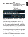
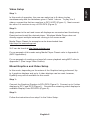
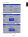
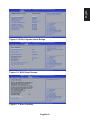
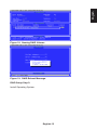
NETPC-BD6C
User’s Manual
BASED ON VERSION
9.001 AMD DRIVER
These documents also discuss the configuration and recommended settings
as implemented with the AMD Video Driver version 9.001. This driver
contains the configuration setups, graphics engine, video decoding, and
display management. The Catalyst Control Center (CCC) manages most
of these features in the driver. For operation of the CCC please refer to the
AMD only documentation for managing modes of operation.
http://www.amd.com/us/products/technologies/amd-catalyst/pages/catalyst.aspx
English-1
English
The purpose of this document is to discuss the uses and various setups for
the Technovare Multiport computer (NETPC-BD6C). The NETPC-BD6C
consists of a GPU and an APU. The APU is an AMD quad core eTrinity
2.3GHz CPU with 8GB of shared memory and an embedded 7660 core for
graphics with 3 video outputs. The GPU is an E6760 with 1GB of independent
video ram, and 6 more video outputs. This graphics card is designated the
MXM card; and, a graphic card standard for embedded graphics. The preinstalled Windows 7 64-bit Operating system enables a large number of
Windows applications to be integrated onto this versatile computer. This
configuration creates a powerful computer capable of driving large video
walls, an array of menu boards, airport applications, and various other multiple
applications.
Modes Of Operation
There are basically 2 main modes of operation for the NETPC-BD6C; a
video player capable of driving multiple videos1, and an accelerated graphics
computer for driving large scale images onto multiple monitors. The Video
Mode is for displaying more than one video; up to 6 videos can be displayed
in this configuration (See Video Modes for more information on this mode)
1. In the Graphics Mode, the CCC Eyefinity is used to allow multiple graphic
processing units to render the same image for increased performance. This
allows the rendering of large images to be displayed on multiple monitors, up
to
Video Mode
The NETPC-BD6C incorporates 2 GPUs, one in the APU, the 7660 and
the E6760; this gives the NETPC-BD6C two independent Universal Video
Decoders (UVDs). These UVDs are used to render video streams in a variety
of formats from WMV (Windows Media format), MPEG (Motion Picture Expert
Group), H.264 (MPEG-4 part 10), and MOV (Apple Movie Format). See Table
1 for a complete list of video resolution and NETPC-BD6C limitations for video
rendering. 720p30 refers to 1280 pixels width by 720 lines in height and the
p30 refers to 30 frames per second (fps) 1080p24 and 1080p30 refer to 1920
x 1080 by either 24 for 30 fps.
When running 1080p30 decoding more than 2 videos may result in a few
dropped frames depending on the actual encoding parameters. Since
there are only 2 UVDs, and each UVD can handle a maximum of 2 videos,
a maximum of 4 videos can be decoded in hardware. To play additional
content, rendering must be accomplished in Software. I.e. running Media
Player Classic (MPC). Also in the configuration required to play up to 4
videos is to connect 2 displays to the APU or Front Side (see Figure 1) and 2
displays connected the MXM side or Back Side (see Figure 2). Since this is a
shared memory architecture, the 2 Additional monitors should be connected
to the MXM side (or DP ports 4 thru 9) for the S/W decoders. In the 6-video
operation, using the MPC for example can be setup to run 4 in hardware and
2 in S/W, and for best results the video encoding of 1080p24.
English-2
Table 1. Video Modes Supported (1) Few Dropped Frames
(2) Video Decoding performed in software
(3) Higher dropped frame count
(4) Same as 3 but When Clips loop video stutters sometimes
(5) Can be used for static pictures (i.e. Menu Board)
(6) Optional Monitoring port
Figure 1. NETPC-BD6C Front Plate. APU Display Ports
Figure 2. NETPC-BD6C Back Plate. MXM Graphics Card Display Ports.
Graphics Mode
Another mode of operation is the Graphics Mode; in this mode the CCC
implements the Eyefinity graphics distribution for acceleration. The
Eyefinity spreads rendering tasks to multiple graphics processors. When
rendering graphics, Flash Content, 3D Modeling, or large-scale picture frame
applications, the maximum resolution for this mode is currently 3840x2160
(2x2), which assumes the monitors running at 1920x1080. Later revisions of
the driver may support larger arrays such as 3x2 or 2x3 configurations, which
would be 5460x2160 or 3840x3240 respectively. Note that this maximum
resolution will also depend on the amount of rendering that needs to be
performed. If it is necessary to create a 3x2 or 2x3, please contact customer
support.
To enable this mode please refer to the online documentation for the Catalyst
Control Center (CCC) from AMD. These steps involve first defining an
Eyefinity Group, 2x2, 1x2 or 2x1. Then locate each monitor’s position in the
Eyefinity group. Then Enable Game Performance Enhancement, named
Eyefinity Enable. An example for setting up a 2x2 Eyefinity groups is also
illustrated in Appendix B of this manual.
Video Decoding results will vary depending on the file format – refer to Table
1 for more information.
English-3
English
Notes:
Connecting Up the Multiport
In order to determine how to connect the NETPC-BD6C, one must determine
the type of application. Is the application graphic, video or both? The
graphics connects all monitors to the Back Plate and the video applications
require a mixture of connections utilizing both front and back of the NETPCBD6C.
Graphics Setup
In order to use the Eyefinity Acceleration, all monitors must be connected to
Display Ports 4 thru Display Port 9 (See Figure 2). Currently the maximum
group that can be configured is 2x2. (To achieve other modes such as 3x2 or
2x3 modes are needed contact Customer Support.)
Step 1:
To use this mode, first the user must initially connect one monitor to the Front
APU side, DP1, 2 or 3 refer to Figure 1. Then apply power to the unit, and
press the <DELETE> key repeatedly until the BIOS window is displayed.
See Figure 3, BIOS Opening Screen, and use the <Left Arrow Key> to select
Chipset, then use the <Down Arrow Key> to select the South Bridge and
press <Enter> (see Figure 8 - BIOS North Bridge). Press the <ENTER> key
again and using the <Down Arrow Key> to change the IGD Graphics to MXM
card, and press <ENTER>. Next, Press <F10> to save and exit (see Figure
5 - BIOS Save and Exit <F10>). Then pull the power cord when the American
Megatrends Logo appears on the Screen.
Now all messages from the Multiport will be forced to output on DP
ports 4 – 9.
Step 2:
Now connect all desired monitors to DP4 thru DP9 (Figure 2). Replace the
power cord and press the Power On Button.
Step 3:
If Graphics Acceleration or a single Windows Desktop is required, follow the
instructions in Appendix B (Setting up an Eyefinity Group).
English-4
Step 1:
In this mode of operation, the user can select up to 6 videos to play
simultaneously with the limitations given it Table 1 above. To play 4 to 6
videos, connect the first two monitors to DP1 & DP3 (Figure 1). Next connect
the other 2-4 monitors to any of DP4-DP9 (Figure 2).
Step 2:
Apply power to the unit and insure all displays are connected and functioning.
Download and install the desired player. Windows Media Player does not
directly support multiple instances running in full screen mode.
Media Player Classic for example can be downloaded from
http://mpc-hc.sourceforge.net
VLC can be found at http://www.videolan.org
For an example of this mode using Media Player Classic refer to Appendix A
(MPC Application).
For an example of creating one large full screen playback using MPC refer to
Appendix C (One Large Video Screen).
Mixed Graphics and Video Setup
In this mode, depending on the nature of the Graphics being performed, Up
to 4 graphics displays and up to 4 video displays can be used; however,
Eyefinity may not be available for this mode.
Step 1:
Connect the Graphics Displays to DP4-DP9 (Figure 2). Connect up to 2 video
displays to DP1, and DP3 (Figure 1). Connect the remaining video displays to
available Display Ports DP4-DP9 (Figure 2).
Step 2:
Follow the instructions from step 2 in the Video Setup.
English-5
English
Video Setup
Using NETPC-BD6C with HDMI Monitors
When using the NETPC-BD6C with HDMI monitors, a DisplayPort to HDMI
dongle is required. We recommend using the ACCELL B086B-001B cable
adaptor. Note that the NETPC-BD6C ONLY supports the use of 3 dongles
at one time. So, if 6 monitors are to be used then 3 can use DP to HDMI
dongles, and the other three must be DisplayPort monitors.
Installing Windows 7 on NETPC-BD6C
Preparation :
Windows 7 (64 Bit is recommended) Installation Disk
AMD Drive found on the included CD or can be downloaded at:
http://www.technovare.com/netpc-multiport.html
Ethernet Driver located on this CD or can be downloaded at:
http://www.technovare.com/netpc-multiport.html
If using RAID, use either the RAID driver on the CD or download the driver at:
http://www.technovare.com/netpc-multiport.html
Installation:
1) If using RAID, please refer to RAID Setup section below.
2) Boot Windows CD
3) If using RAID, Windows will prompt the user to install the driver for the RAID.
Correct driver for Windows 7 64b can be found at RAID->vista_win7->64B
4) Complete the installation of Windows
5) Install the AMD Drivers by navigating to the setup under the AMD directory
of the enclosed CD.
6) The unit will reboot.
7) Install the Ethernet Drivers by navigating to Ethernet on the CD and
selecting Setup.
8) Installation should now be completed.
English-6
English
BIOS SCREENS
Figure 3. BIOS Opening Screen
Figure 4. BIOS Load Optimized Defaults - <F8> or <F9>
Figure 5. BIOS Save Configuration – <F10>
English-7
Figure 6. BIOS Advanced
Figure 7. BIOS Chipset
Figure 8. BIOS-Chipset-NorthBridge
English-8
English
Figure 9. BIOS-Chipset-South Bridge
Figure 10. BIOS Boot Screen
Figure 11. BIOS Security
English-9
Figure 12. BIOS Save & Exit Screen
RAID Setup
To setup a RAID from new hard drives, follow these instructions.
RAID Setup Step 1:
Apply power, and press the Power Button. Then apply power to the unit, and
press the <DELETE> key repeatedly until the BIOS window is displayed.
Then Press <F8> to load optimized RAID defaults and the press <F10> to
save these settings. The Multiport will restart, and once the RAID message
appears on the Screen – “RAID Option ROM Version 3.3.1540.11 …” press
the <CTRL> <F> keys to enter the BIOS Utility. See Figure 13 below.
Figure 13. RAID Initial Screen
English-10
Press the <2> key. This should now show the LD View Menu, See Figure 14
below.
Figure 14. Define RAID beginning Screen
RAID Setup Step 3:
Press <CTRL> <C> to define a new RAID (See Figure). Press <ENTER> to
select the RAID mode See Table 1 for definitions of the currently supported
RAID modes. Then repeat pressing the <Down Arrow Key> until the first
selected hard drive is highlighted. Then press the <Y> key to add to the
RAID, then press the <Down Arrow Key> and <Y> key until all the desired
drives are added to the RAID. (See Figure 15 below)
Figure 15. Defining RAID
English-11
English
RAID Setup Step 2:
LEVEL
Description
Minimum # of Drive
RAID 0
Block Level Striping (Drives are Added)
2
RAID 1
Mirroring
2
Table 2. RAID Modes
Figure 16. Completed Definition of RAID
RAID Setup Step 4:
Press <CTRL><Y> to save the RAID then press <CTRL><Y> again to confirm
(See Figure). Then enter the name of the RAID Volume, in this example
“MultiportRaid” (See Figure). After entering the name of the volume press
the <ENTER> then <CTRL><Y> to save and then the Space bar to use all
available space on the volume. Then press the <Y> key to reboot.
Figure 17. RAID Erase Warning
English-12
English
Figure 18. Naming RAID Volume
Figure 19. RAID Reboot Message.
RAID Setup Step 5:
Install Operating System.
English-13
Appendix A
Media Player Classic (MPC) Example
Connect up to 6 monitors to the NETPC-BD6C
2 monitors to the CPU/Front Side
Up to 4 monitors to the MXM/Back Side
Right-Click on the Desktop and select Screen Resolution
Make certain that the displays are all in “EXTEND” mode
Arrange the Monitors into the locations as mounted -- This makes it easier to
navigate the mouse and set up the players later.
Download the latest version of MPC (currently 1.6.3) from sourceforge.
http://mpc-hc.sourceforge.net/downloads/
(6) Install the software to c:\Program Files\
-- Or copy depending on the downloaded version
Place Desired Media on the system
Launch the First Copy of MPC
Select VIEW->Options
Select Playback
Enable Repeat Forever Option
Select Output
Ensure that the EVR or EVR Custom is selected.
Select FullScreen
Select “Launch Files in Full Screen”
(13) Apply and Close
(14) Launch up to 6 (one per connected monitor) copies of MPC and
locate one on each screen
(15) When running 5 or 6 monitors, Locate 2 (when using 6 displays) or 1
(when using 5 displays) monitors connected to the MXM Graphics Card and
configure these 1 or 2 MPC players as follows:
View->Options
Select Output
Select System Default at the top of the list
Press (OK) button
(16) For Each of the MPC: Select File->Quick Open
Select the desired file. The File should play in full screen mode and no further
actions should be necessary.
English-14
Setup Catalyst Control Center (CCC) for Mulitple Monitor Eyefinity
Display Group
Multiport Connection Setup
- On first boot, you will want to have one of the displays connected to a
DisplayPort connection on the side of the Multiport where the power
connects.
o The AMD CPU powers the ports on this side.
- Connect the three remaining displays to the opposite side of the
Multiport and power on the unit.
o The MXM discrete graphics card powers the ports on this side.
Eyefinity/Display Configuration
- Once the unit boots to the Windows Desktop, right click on the Desktop
and select the “AMD VISION Engine Control Center”.
- Scroll down to the “Performance” section and click the link for “AMD
Radeon Dual Graphics”.
- Select the radio button “Enable AMD Radeon Dual Graphics”
and click “Apply”.
o Note: The computer may take a while to respond and update the
graphics properties.
- Once the settings take, disconnect the one display from the CPU side
of the system and move it to an open connection on the MXM side of
the system.
- Still in the AMD VISION Engine Control Center, click on the start tab
toward the top of the window.
- Under “Desktops and Displays”, select the “Desktop Management” link,
followed by the “Arrange Desktops” link.
- Click “Identify All” and arrange the displays in a 2x2 matrix in the
control center.
o For instance, if the display which is set up in your display wall in the
top-left position is labeled display 3 when you click “Identify All”, you
would want to move display 3 in the control center such that it
appears in the top-left corner.
- Click “Apply” and then click on the “Desktops and Displays” tab at the
top of the window.
- Scroll down to “AMD Eyefinity Multi-Display”, and select the
“Create Eyefinity Display Group” link.
- Click on the top-left display and then click “Continue” in the bottom-right
corner of the window.
English-15
English
Appendix B
- Click the drop-down menu, detailing the number of displays you want in
your Eyefinity group, and select “4 Displays (2 x 2)”.
Then select “Continue”.
- Next, click the “Arrange” button and when a display lights up blue, click
on that corresponding display in the window. Then, click “Done”.
- Exit the “AMD VISION Engine Control Center.
Appendix C
One Large Screen Video
(1) Follow Steps in Appendix B to Setup an Eyefinity Group using CCC
(2) Follow Steps 5-13 in Appendix A, Installing and Configuring MPC
(3) Select File->Quick Open and Select the desired File
Eyefinity and AMD are trademarks of Advanced Micro Devices Inc.
Windows 7, Windows XP are trademarks of Microsoft Corporation
English-16