1
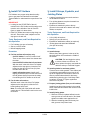
SensorRail™ IIIE
ADRL3TRK Series
About this Guide
SpeedDome® Ultra Programmable
Dome on a Rail
Installation Guide
• Determine the exact mounting location of the
rail. This is determined by the customer’s needs
and the site’s ceiling structure.
This guide explains how to install the SensorRail
IIIE system. It does not explain how to:
• Program or operate the system. See SensorRail
IIIE User Guide 8200-0593-04 and SpeedDome
Ultra and AD Matrix User Guides.
CAUTION: Only a certified installer is
authorized to install this equipment.
Installation by anyone else will void the
SensorRail warranty.
• Service the system. See Service Guide
8200-0593-03.
If you need assistance...
Contact your certified support representative.
Contents
About the Product
About this Guide ............................................................ 1
About the Product .......................................................... 1
Before You Begin........................................................... 3
Installation Steps ........................................................... 5
1. Install Threaded Rods ............................................ 5
2. Install PVC Holders ................................................ 6
3. Install Stirrups, Eyebolts, and Jointing Plates ........ 6
4. Install Rail Sections................................................ 7
5. Install Anti-Sway Cables ........................................ 8
6. Insert Copper Tracks
and Trolley Stop/Retrieval Tool .................................. 9
7. Install Optical Stop Labels.................................... 10
8. Install the PowerRail Module................................ 11
9. Install the Camera Trolley .................................... 12
10. Attach Light Reducing Sections ........................... 13
11. Clean the Rail ...................................................... 13
12. Check Electrical Connections .............................. 13
13. Configure the System .......................................... 14
14. Install the Cowling................................................ 15
15. Install End Covers................................................ 16
Ordering Parts ............................................................. 17
Specifications .............................................................. 20
Declarations................................................................. 21
The SensorRail IIIE system enables a SpeedDome
Ultra dome camera to transmit video as it moves
along a rail to the ideal surveillance position.
The system consists of:
•
•
•
•
•
•
•
•
2.5m (8.2ft) rail sections (number determined by the
total length of the rail) with installation hardware
A light-reducing section at each end of the rail
Ceiling suspension assembly, which includes M8
threaded rods, ceiling attachment hardware (not
supplied), and mounting stirrups
Copper tracks
Camera trolley equipped with dome camera, RF
transmit antenna, and motor
PowerRail module that supplies dc power to the
camera trolley, converts RS-422 data to RS-232 data
used by the trolley, and receives the video signal
from the dome camera
Trolley stop and retrieval tool
RF receive antenna.
IMPORTANT! At least two people are required to
install this product safely and efficiently. Follow all
procedures described in this guide explicitly. If
installation difficulties occur, call:
Appendix A: RF link DIP switch settings .................... 32
Appendix B: Alternate RF antenna location ............... 32
American Dynamics Technical Services
Toll Free 800-507-6268, Option 2
International: 561-912-6259, Option 2
Appendix C: AD SensorRail Control Utility................. 33
In Europe:
Technical Services at EMEA AD Technical Support
+800 CALL TYCO or (+800 22 55 8926)
From the UK: 08701 238 787
Direct: +31 475 352 722
© 2006 Sensormatic Electronics Corporation
SENSORRAIL IIIE ADRL3TRK SERIES
INSTALLATION GUIDE
8200-0593-02, REV. A
1 of 34
Product Features
Start End of Rail
(see below)
Light Reducer
(one at each
end of rail)
M8 Locking Nut
Crisscrossed
Anti-Sway
Cables Every
15m (49.2ft)
M8 Threaded Rod
PowerRail
Module
Jointing Plate
(4 per section)
Stirrup
Collector (4)
Optical Stop
Label (one at
each end of rail)
End Cover (2)
Dome Camera
Camera Trolley
RF Tx Antenna
RF Rx Antenna
Mirrored
Cowling
Rail Section
Optical Spot Label
(one per rail)
PVC Holder
w/copper tracks
Top Grooves
for jointing plates
Rolling Track (2)
PVC Holder
Side Grooves (2)
for jointing plates
Stop Groove
Start End of Rail
Bracket Grooves (2)
for Rx Antenna
Cowling Grooves
Vision area (for surveillance), dead zones (for stopping), and maintenance areas (for servicing)
Rail
Vision Area
Vision Area + Two 1.5m (4.9ft) Dead Zones
Vision Area + Two 1.5m (5ft) Dead Zones +Two 30cm (1ft) Light Reduction Sections = Total Length of Rail
Total Length of Rail + Two 0.6m (2ft) Maintenance Areas
SENSORRAIL IIIE ADRL3TRK SERIES
INSTALLATION GUIDE
8200-0593-02, REV. A
2 of 34
Acoustic Tile Ceilings
Before You Begin
WARNING! DO NOT mount the rail
structure directly to an acoustic tile
ceiling; it cannot support the weight.
Instead, extend threaded rods through
the tile to a rigid ceiling structure capable
of supporting the weight.
IMPORTANT! Proper installation requires:
• Observing safety guidelines
• Analyzing the ceiling structure along the
proposed rail route
• Considering space needed to service the rail
Space Requirements
• Considering space needed to install the
PowerRail module
Allow at least:
• Considering distance to nearby lights to prevent
them from silhouetting the camera location
• 60cm (24in) from the ends of the rail to vertical
surfaces, such as walls to enable the camera
trolley to be removed and serviced.
• Determining the location of ceiling suspension
assembly components, such as M8 threaded
rods and anti-sway cables
• 50cm (20in) of vertical space above the rail to
install the PowerRail module.
• Knowing parts supplied, parts to be purchased,
and tools and equipment required
• 23cm (9in) from the rail to nearby lights
• Understanding the installation process by
reading procedures in this guide in detail before
beginning installation.
Safety Guidelines
The rail system must conform with all applicable
Standards or Codes of Practice pertaining to the
country or state in which it is to be installed.
Specifically:
Because lights can silhouette the dome
camera, making it visible to people below the
rail, factor in the installation height of the rail
to nearby lighting.
-
Ensure the gap between the rail and the
lighting system is no more than 5cm (2in) to
reduce artifacts inside the cowling.
IMPORTANT! Installing the rail
perpendicular to a tube-type lighting system
may cause more artifacts than when it is
installed in parallel.
• Certified electricians (in accordance with local
regulations) must be used to install mains power
cabling and termination.
Lay Out the Structure on the Ground
Lay out the rail system on a piece of paper to
identify ceiling obstacles along the route, lighting
that can affect covert operation, and where to place
the anti-sway cables.
• Licensed machinery operators must be used
during installation of the system.
• A dedicated power circuit equipped with a 6A
breaker and 30mA differential must be allocated
to the system.
Anti-Sway Cable Locations
• Exposed and external cables must be placed in
conduit or sheathed in cable wrap.
To prevent the rail from swaying, two anti-sway
cables angled out no more than 35° from vertical
are installed at each end of the rail. Additionally:
Ceiling Irregularities
• For rails 9.1m (30ft) or less, one crisscrossed
anti-sway cable is installed at the center of the
rail.
CAUTION: DO NOT mount the rail
directly to the ceiling. Irregular ceilings
can distort the rail and damage it as the
ceiling expands and contracts.
• For rails 9.1m (30ft) or more, anti-sway
crisscrossed cables are installed vertical to the
rail every 15m (49.2ft) as required.
A Hilti MF C31/8 fast grip system and Hilti MQ-41
suspension bar (not supplied) may be required to
attach the rail to ceiling red iron.
SENSORRAIL IIIE ADRL3TRK SERIES
INSTALLATION GUIDE
-
• If the last two crisscrossed anti-sway cables
cannot be separated by 15m (49.2ft), then
reduce spacing between all crisscrossed cables
to make them equidistant.
8200-0593-02, REV. A
3 of 34
Parts Supplied
Parts to be Purchased Separately
Note: The number of parts supplied depends on
the length of the rail.
• M8 threaded rods and related hardware, and
ceiling connection assemblies
• Rail section package, which includes:
• 3.3mm (1/8in) cable (as needed), steel
galvanized 7x19 strands, minimum working load
limit 680kg (1500 lbs)
-
2.5m (8.2ft) straight rail sections
-
2.5m (8.2ft) PVC holders
-
Stirrups, 1 per rail section
-
Jointing plates, 4 per rail section
-
Screws for jointing plates.
• 8mm (5/16in) galvanized eyebolts, 317kg
(700 lbs) minimum working load limit
• U-bolt clamps and wire thimbles for 3.3mm
(1/8in) cable
• 9.6mm (3/8in) minimum size diameter jaw & jaw
turnbuckles, 544kg (1200 lbs) break strength,
362kg (800 lbs) minimum working load limit
• Rail accessories package, which includes:
-
End covers (2) with attachment hardware
-
Springs for service stop blocks (2)
-
Stop screws (2)
-
Nylon service blocks for mechanical stops
and trolley retrieval (2)
-
Optical stop strip (1 roll)
• SensorNet-to-RS422 code converter for VM16,
VM32 and MegaPower LT video controllers, if
used. The AD1024 matrix switcher requires a
2083 converter.
Tools and Equipment Required
• Light reduction kit
-
• Proper lift equipment (scissor lift with extended
work platform is recommended)
30cm (11.8in) section w/top hat cover (2).
• Hilti PR-15 rotating laser leveling device
• Trolley package
-
-
• 60cm (2ft) bubble level
Camera trolley with 2.4GHz RF transceiver,
CPU, SpeedDome Ultra dome camera, and
motor
• String line
• Battery-powered drill, ½-inch
PowerRail 90–240Vac (50/60Hz) to 27Vdc
power supply with RS-422 to RS-232
connections, 2.4GHz receiver, PAL.
• Metric screwdrivers and Allen wrenches
• M13 open wrench
• Cowling package
• 0.1–5mm feeler gauge set
• Copper tracks package
• Common hand tools, such hammers, cutters,
and pliers
-
Wheels to hold copper tracks
-
Support structure for wheels
-
Service trolley
-
Steering wheel to retrieve copper tracks for
servicing.
• Copper track installation/retrieval tool
• Torque wrench
• Soldering iron
• Laptop with AD SensorRail Control application
installed and a serial port or USB-to-serial port
Note: The tool used to install copper tracks is
not supplied with the system.
• Protective gloves (surgical or cotton type)
• Protective eyewear
• Plastic card similar to a credit card
• Ruler
• Cleaning pads and tissues (for fingerprint
removal upon completion).
SENSORRAIL IIIE ADRL3TRK SERIES
INSTALLATION GUIDE
8200-0593-02, REV. A
4 of 34
1. Install Threaded Rods
Installation Steps
Threaded rods secure the rail system to the ceiling.
Each rod attaches to the ceiling using one of the
following methods:
The following step numbers refer to pull-out
drawings at the end of this document.
CAUTION: Perform all steps carefully
and methodically. DO NOT skip steps!
1.
2.
3.
4.
5.
6.
7.
8.
9.
10.
11.
12.
13.
14.
15.
Install threaded rods
Install PVC holders
Install stirrups, eyebolts, and jointing plates
Install rail sections
Install anti-sway cables
Insert copper tracks and
trolley stop/retrieval tool
Install optical stop strips
Install PowerRail module
Install camera trolley (complete trolley
stop/retrieval tool assembly)
Attach light reducing sections
Clean rail
Check electrical connections
Configure system
Install cowling
Install end covers.
-
Direct into the ceiling
-
To red iron ceiling supports using a “fast grip”
system such as a HILTI MF C31/8
-
To a suspension bar such as a HILTI MQ-41
between red iron when ceiling supports are
spaced more then 2.5m (8.2ft) apart.
The bottom of each rod attaches to a stirrup at the
top of the rail section.
Tools, Equipment, and Parts Required for
this Operation
• Proper lift equipment (scissor lift with extended
work platform is recommended)
• Hilti PR-15 rotating laser leveling device
• String line
• M8 threaded rods (one per rail section)
• Saw (to cut rods)
• M8 nuts (one per rod).
Procedure
Note: Observe space requirements (page 3).
Installation Requires a
Laser Leveling Device
A. Run a string line.
• Centered along the rail route
A Hilti PR-15 rotating laser leveling device is used
to level the rail during installation. Set the beam to
intersect with a prominent horizontal feature on the
rail.
• 10cm (4in) higher than the top of the rail.
Tack the string in place.
B. Install the first threaded rod.
WARNING! Wear protective eyewear
when using a laser leveling device. Refer
to the device manufacturer’s instructions
for additional safety precautions.
Each rod supports a rail section at its center.
Install the first rod 1.25m (5.1ft) from where the
first 2.5m rail section is to start.
C. Install subsequent threaded rods.
From the first rod, install subsequent rods every
2.5m (8.2ft) along the string line to the point
where the last rail section will be located.
D. Thread nuts.
On each rod, thread a nut up until its bottom
touches the string line and 5cm (2in) of rod is
below the nut.
E. Saw off any extra rod length beyond 5cm
(2in). Do not use a cutter.
SENSORRAIL IIIE ADRL3TRK SERIES
INSTALLATION GUIDE
8200-0593-02, REV. A
5 of 34
2. Install PVC Holders
3. Install Stirrups, Eyebolts, and
Jointing Plates
PVC holders carry copper strips that the trolley
uses to get power and send and receive data.
These holders lie underneath the top surface of the
rail.
• A stirrup is required to mount each section to
the threaded rod above.
• Four jointing plates are required to attach it to
the previous rail section.
IMPORTANT!
• Looking into the START END of the rail,
notches for the PVC holder and the stop groove
must be on the left side of the rail. See the
figure on page 2 for these items.
• Eyebolts are attached in pairs to the top
grooves in the overall rail to attach “anti-sway”
cables, as required.
Tools, Equipment, and Parts Required for
this Operation
• Each PVC holder has notch running along one
side of it. Ensure the notch is adjacent to the
stop groove in each rail.
•
•
•
•
Tools, Equipment, and Parts Required for
this Operation
• PVC Holders (one per rail section)
• Saw to cut PVC holder
• M6 self-tapping screw.
Procedure
A. Install stirrups.
Procedure
Slide a stirrup along grooves in the top of the
each rail section until it reaches the middle of
the section.
A. For first and last rail sections only.
-
-
-
2.5m (8.2ft) rail sections
Stirrup (one per rail section)
Eyebolts for stabilization cables (as required)
Jointing plate and associated hardware
(four per rail section).
Cut PVC holder. Cut a PVC holder in half.
Then cut one of the halves 5cm shorter than
the other.
CAUTION: Pull and wiggle the stirrup
to ensure it does not come out. If it
does, replace the stirrup, and send the
defective stirrup to Technical Support.
Insert half PVC holder that is 5cm shorter.
With the notch in the side of the PVC holder
adjacent to the stop groove, insert the PVC
holder into the rail until it is 5cm (2in) from
the start end of the rail.
B. Install eyebolts for anti-sway cables.
Thread nuts on cable eyebolts. Then slide a pair
of eyebolt/nut assemblies into grooves in the
top of the appropriate rail sections, and move
them to positions determined for anti-sway
cables during planning (see “Anti-Sway Cable
Locations” on page 3). Tighten eyebolts to
secure them in place.
Install self-tapping screw. Install a selftapping screw 5cm (2in) from the start end of
the rail (where shown) to prevent the trolley
from shifting the PVC holder out of the rail.
B. For all other rail sections.
With the notch in the side of the PVC holder
adjacent to the stop groove, slide the PVC
holder halfway into the rail.
C. Prepare jointing plates (four per rail section).
Install the two large Allen screws in the outside
holes. Install the two smaller Allen screws in the
inside holes.
Note: The other half of the holder will remain
outside the rail. This half will insert into the next
rail section.
D. Install jointing plates.
1. Slide one of the four plates halfway into the
outer grooves of each rail section, and handtighten its outside screw against the rail.
2. Slide the remaining plates all the way into
their grooves. Keep them loose.
SENSORRAIL IIIE ADRL3TRK SERIES
INSTALLATION GUIDE
8200-0593-02, REV. A
6 of 34
C. Level the rail sections.
4. Install Rail Sections
1. Level sections by adjusting the two center
screws in the top jointing plates.
Rail sections connect end-to-end to create the
camera route. Repeat this procedure for each rail
section until the total rail is complete, as straight as
possible, and uniformly butted.
2. At the joint, check the top surface of the
rolling track within the rail for misalignment
that can cause the camera trolley to vibrate.
Note:
3. Once leveled, tighten the stop nuts under the
stirrups.
• The rail should look straight, but does not have
to be precisely straight.
D. Straighten the rail sections.
• TAKE YOUR TIME aligning rail segments.
Cumulative misalignment can cause a
noticeable curve in the rail.
1. Place the laser leveling device in horizontal
mode, and run the beam along the rail.
• A single rail section attached to a threaded rod
will sway, making subsequent rail installation
difficult. Therefore, for ease of installation, the
first two rail sections are joined on the ground
BEFORE they are attached to the rods.
2. Measure the gap between the beam and the
side of the rail; it should not be more than
1cm (0.4in). If the gap is greater than 1cm,
repeat step C.
BE CAREFUL. Maximum joint gap cannot
exceed 0.4mm (0.016in). Use a feeler gauge
to verify.
Tools, Equipment, and Parts Required for
this Operation
3. If necessary, straighten sections by adjusting
the two center screws in the side jointing
plates.
• Proper lift equipment (scissor lift with extended
work platform is recommended)
• Hilti PR-15 rotating laser leveling device
• 2.5m rail sections required to complete rail
• M8 locking nuts (one per rail section).
Note:
• The rail should look as straight as possible,
but does not have to be precisely straight.
However, how straight and level the sections
are IS IMPORTANT because they determine
how straight the finished rail will be.
Procedure
A. Join two rail sections on the ground.
• Despite efforts, the rail can bend up to 10cm
(4in) from one end to the other due to the
cutting tolerance of the aluminum (0.2mm).
1. Uniformly butt the rail sections together by
sliding the mating groove of one section over
the protruding jointing plate of the other.
There should be no space between the two
sections. Also, each exposed PVC holder
should insert into the adjacent rail section.
E. Attach each subsequent 2.5m rail section to
the rail.
1. Using the scissor lift, raise the next rail until it
aligns with the previous section and the top
of the stirrup is against the nut on the rod.
2. Center the loose jointing plates over the joint
and hand-tighten the outside screws of all
plates.
2. Repeat steps B–D.
B. Attach the rail sections to the threaded rods.
1. Using the scissor lift, raise the sections until
the rods just touch the holes of each stirrup.
2. CAREFULLY raise sections further until the
rods enter the holes in the stirrups and the
top of the stirrups are butted against the nuts
on the rods.
3. Secure each rail section to the rod using a
Nylon stop nut. DO NOT tighten the nut.
SENSORRAIL IIIE ADRL3TRK SERIES
INSTALLATION GUIDE
8200-0593-02, REV. A
7 of 34
5. Install Anti-Sway Cables
Procedure
The single row of threaded rods can cause the rail
to potentially swing. To prevent this:
At the ceiling:
A. Install I-beam clamps on the side of the
beam opposite the cable pull direction.
• Install two anti-sway cables at each end of the
rail.
CAUTION:
B. Thread an eyebolt into the beam clamp
where the rod would normally go.
-
C. Insert a cable thimble into each eyebolt.
-
Locate landing points in the ceiling
structure that do not allow the
cable to angle more than 35° from
vertical in any direction.
D. Loop the cable around the thimble and
secure it using two U-bolts.
Cables must meet all safety and
regulatory guidelines.
CAUTION: Note the right way to
secure the cable for maximum
strength. Minimum cable turnback is
82mm (3.25in).
• Install crisscrossed cables as determined during
the planning stage (see page 3).
At the rail:
Tools, Equipment, and Parts Required for
this Operation
E. Attach a turnbuckle to each eyebolt.
F. Insert a cable thimble into the unused jaw of
each turnbuckle.
• Proper lift equipment (scissor lift with extended
work platform is recommended)
G. Loop each cable around its respective
thimble and secure it using two U-bolts.
• Unistrut I-beam clamps rated for 294.8kg (650
lbs) using 5/16in rod or M8
• 3.3mm (1/8in) cable, steel galvanized 7x19
strands, 680kg (1500 lbs) minimum working
load limit
CAUTION: Note the right way to
secure the cable for maximum
strength. Minimum cable turnback is
82mm (3.25in).
• 8mm (5/16in) diameter galvanized eyebolts;
shoulder lifting eyes smaller length threads,
317kg (700 lbs) minimum working load limit
Ensure cables are taut by tightening each
turnbuckle to 1.4–2kg-meters (3–4.5ft-lbs) with
a torque wrench.
• U-bolt clamps, wire thimbles for 1/8-inch cable
• 9.6mm (3/8in) diameter jaw & jaw turnbuckles;
544kg (1200 lbs) break strength, 362kg (800
lbs) working load limit.
SENSORRAIL IIIE ADRL3TRK SERIES
INSTALLATION GUIDE
8200-0593-02, REV. A
8 of 34
C. Insert the service trolley “handle first” into
the rail.
6. Insert Copper Tracks and
Trolley Stop/Retrieval Tool
D. Assemble the reel that holds the rolls of
copper track.
Four copper tracks feed 27Vdc power and RS-232
data to the camera trolley. A track installation/
retrieval tool (supplied separately) is used to insert
copper tracks and can be used to retrieve copper
tracks for servicing.
1. Lay out the five supplied wheels on the
ground and insert six screws in one of the
wheels.
2. Place a copper roll on the wheel with the six
screws; then place another wheel on top of
the roll.
Note: During this step, a trolley stop/retrieval
assembly is inserted and pulled into position.
CAUTION: Ensure copper tracks are not
bent or wavy when they are inserted into
the PVC holder. Bends or waves make
installation difficult and will affect
operation of the camera trolley.
CAUTION: To prevent the copper
strip from unraveling from the roll,
DO NOT remove the tie wrap until
roll is clamped between two
wheels.
Tools and Equipment Required for this
Operation
3. Repeat step 2 above for the next three rolls.
Use the fifth wheel and five bolts supplied to
clamp all the wheels together.
•
•
•
•
Cutter, pliers
Copper track
Soldering iron
Track installation/retrieval tool
(supplied separately)
• Trolley stop/retrieval assembly consisting of
1 service block, 1 spring, 1 M8 screw with nut,
and strapping tape.
5. Bolt left and right axles to the wheels using
six bolts per axle. Ends of axles are marked
“L” for left and “R” for right.
E. Assemble the support structure that holds
the copper reel.
F. Insert the support structure into the starting
end of the rail.
Procedure
Insert the structure into the grooves in the side
of the rail, and tighten it in place using the four
screws.
A. Install a spring and screw into the stop
groove at the end of the rail.
Insert the spring into the end of the rail. Then
thread an M8 nut on the screw. Install the screw
5cm (2in) from the end of the rail and tighten.
G. Place the copper reel onto the support
structure.
Place the left and right axles of the wheel
assembly into the slots of the support structure
and lock the axles in place. Looking into the
beginning of the rail, the left axle faces left.
B. Attach strapping tape to a service block and
insert it into the stop groove at the start end
of the rail.
1. Fold the strapping tape 1.9cm (.75in) back
on itself. Then make a small hole in the
folded section using a soldering iron.
H. Insert the copper track, and pull the tape to
the end of the rail.
1. Insert each copper strip into its respective
slot in the PVC holder.
CAUTION: DO NOT punch a hole in
the tape; the material will break! Use
a soldering iron instead.
2. Roll the service trolley over to the strips until
its four pins align with grab holes in the
copper tracks. Then shift the pins up against
the PVC and tighten them in place using the
two screws on the side of the trolley.
2. Remove the M3 screw from the service
block, and insert it through the hole in the
folded section of tape and into the block.
3. Temporarily insert the second service
block—slit first—into the stop groove to hold
the tape in place at the start end of the rail.
3. Tighten the screw to secure the tape.
4. Insert the service block with the tape
attached. Ensure the tape faces the start end
of the rail.
SENSORRAIL IIIE ADRL3TRK SERIES
INSTALLATION GUIDE
8200-0593-02, REV. A
9 of 34
4. Pull the trolley along the entire rail until the
trolley and copper tracks exit the other end
of the rail.
7. Install Optical Stop Labels
Optical stop labels affix inside the rail nearest the
PVC holder to enable the trolley to recognize the
beginning and end of its route.
IMPORTANT! While pulling the service
trolley, hand push the service block with the
tape attached to where it touches the spring
at the end of the rail. Remember, the tape
must face the start of the rail.
WARNING! Beginning and end optical
stop label locations are different.
Incorrect label application can cause a
hazardous situation.
5. Detach the copper tracks from the trolley.
WARNING! Stop labels are made of
special tape that enables the optical
sensor in the trolley to work. Do not use
any other tape.
6. Cut the tape approximately 50cm (19.7in)
beyond the rail. This excess will be used as
a pull to manually retrieve the trolley if
control of the trolley is lost.
Note: DO NOT pull the tape; it can move the
stop block at the other end of the rail.
Tools, Equipment, and Parts Required for
this Operation
I. Bend excess copper at both ends of the rail.
• Proper lift equipment (scissor lift with extended
work platform is recommended)
• Roll of label tape (1) cut into three equal 2.5m
pieces.
1. Cut off excess track leaving 2cm (.8in) of
copper track out of the PVC holder at the
START and END of the rail.
2. At the start end of the rail, bend excess
copper track over the PVC holder to make
an “S” shape that will be used to connect
power and data crimp connectors.
Procedure
A. Affix the beginning stop label.
1. Cut 10cm (3.9in) from the length of the
beginning stop label.
WARNING! Ensure copper tracks
do not touch each other or any
part of the aluminum structure.
2. Place this label above and adjacent to the
raised line in the first rail section.
J. At the end of the rail, bend the excess
copper track over the PVC holder.
Note: Keep the end of the label flush with
the start end of the rail. The other end of the
label should end 5cm (12.7in) from the spot
label.
K. Remove the copper track installation/
retrieval tool from the rail.
B. Affix the two end stop labels.
These labels must:
• Be affixed adjacent to the raised line in the
last rail section; one above the line, the other
below it.
• Overlap the last rail junction by 3mm.
C. Remove the spot label ONLY from the last
rail section.
Note: A spot label is applied during
manufacture at the end of each rail. If a spot
label is missing or improperly placed on any of
the rails, call Technical Support to report the
problem. Meanwhile, cut a new spot label the
same size as the old one from the roll of label
tape. Place the new label where the old one
should be.
SENSORRAIL IIIE ADRL3TRK SERIES
INSTALLATION GUIDE
8200-0593-02, REV. A
10 of 34
D. Connect RS-422 data from the video
controller to the module.
8. Install the PowerRail Module
The PowerRail module:
Matrix
RS-422
• Converts RS-422 signals from the video
controller to RS-232 signals.
TX+
• Sends and receives RS-232 signals from the
camera trolley
• Receives video from the camera trolley and
sends it to the video controller for display on a
monitor.
PowerRail
RS-422
goes to
RX+
TX–
goes to
RX–
RX+
goes to
TX+
RX–
goes to
TX–
E. Connect the RF antenna cable.
The module mounts to the top of the first rail
section.
Connect the SMA cable to the PowerRail
module; and then run the cable from the
PowerRail module to the location for the RF
receiving antenna.
Tools, Equipment, and Parts Required for
this Operation
F. Connect AC to the module.
• Proper lift equipment (scissor lift with extended
work platform is recommended)
• PowerRail module
Have a certified electrician connect the
PowerRail module to the ac power source.
Ensure the power switch on the module is in the
off position.
• Power, data, and RF antenna cables
• Crimp connectors.
Procedure
A. Bolt the module to the rail.
45cm (17.7in) from the start end of the rail,
secure the module to the top of the rail using
four plastic screws, washers and M8 nuts
installed in the top grooves of the rail. Ensure
the RF cable from the module reaches the
intended antenna mounting site within the rail.
B. Connect power from the module to the rail.
Attach one end of the 27Vdc and ground wires
to the module, and crimp their other end to the
rail. Ensure wires are long enough to reach the
copper tracks without stretching.
C. Connect data from the module to the rail.
Attach one end of the Tx (RS-232 data) and Rx
(RS-232 data) wires to the module and crimp
their other end to the rail. Ensure wires are long
enough to reach the copper tracks without
stretching.
SENSORRAIL IIIE ADRL3TRK SERIES
INSTALLATION GUIDE
8200-0593-02, REV. A
11 of 34
B. Remove the service block at the start end of
the rail holding the tape in place and slide
the camera trolley onto the rail.
9. Install the Camera Trolley
As the camera trolley moves along the rail, it
transmits video and camera data to the PowerRail
module, which sends them to a monitor via a video
controller. Four sliding collectors on the trolley
transfer power and data to the rail.
Note: The four sliding collectors compensate for
linearity differences that may occur along the rail.
Two sliding collectors are at each end of the trolley.
Tools, Equipment, and Parts Required for
this Operation
With its antenna facing the starting end of the
rail, carefully insert the trolley wheels onto the
rolling track, and roll the trolley about 1m (3.3ft)
down the rail.
C. Install the RF receiving antenna.
1. Insert the plastic bracket supplied with the
antenna into the rail where shown and about
15cm (6in) from the start end.
Note: To enable transmit and receive
antennas to align with each other, bracket
holes used to mount the antenna must be
closer to the left side of the rail when viewed
from the start end.
• Proper lift equipment (scissor lift with extended
work platform is recommended)
• Camera trolley
• Bracket and associated hardware for RF
receiving antenna
2. Attach the RF receiving antenna to the
plastic bracket using two screws. Align the
antenna so it is directly facing the receiving
antenna on the trolley.
• Attenuator for the RF transmitting antenna
• RF receiving antenna.
3. An RF attenuator matched to the rail length
is attached to the transmitting antenna. If the
rail length is different, change the RF
attenuator according to the table below.
Procedure
A. Prepare the dome camera.
1. Detach the dome camera from the trolley,
but do not detach the cables.
CAUTION: The attenuator is
required to comply with the CE
regulation.
2. Gently remove the lens from the dome
camera’s slot cover.
a. Gently swivel the eyeball of the dome
camera to totally expose one of two slot
covers.
CAUTION: Swiveling fast can
damage gears.
RF Attenuator
10–45m
50–75m
75–100m
30dB
20dB
10dB or 15dB
4. Connect the SMA cable from the PowerRail
module to the antenna.
b. Insert a small, thin-bladed screwdriver
into the space between the cover and
the eyeball.
D. Install the trolley stop assembly.
1. Thread two M8 nuts onto the stop screw.
c. Gently pry off the slot cover containing
the lens.
2. At the start end of the rail, slip the second
service block, a spring, and a stop screw
(with nuts) into the stop groove and under
the strapping tape.
d. Pop the lens from the slot cover, and
snap the cover back onto the eyeball.
3. The camera’s address is preset to “1”. Set
the required address for the rail.
3. With the stop screw 5cm (2in) from the start
of the rail and its tip 3mm (0.12in) from the
top of the groove, tighten the stop screw.
4. Insert the dome back into the mounting
base, and twist it to lock it in place.
4. Ensure that each block is lightly pushing the
spring against the stop screw, and the
strapping tape exits 50cm (19.7in) beyond
the rail.
IMPORTANT! Ensure wires are not caught
in the latching mechanism before locking the
dome in place.
SENSORRAIL IIIE ADRL3TRK SERIES
INSTALLATION GUIDE
Rail Distance
8200-0593-02, REV. A
12 of 34
10. Attach Light Reducing
Sections
11. Clean the Rail
Light reducing sections are not used by the camera
trolley, but rather to reduce light that can enter the
cowling from the ends of the rail. A light reducing
section attaches to each end of the rail.
The rail is sensitive to fingerprints. To clean the
rail, use a tissue soaked with window glass cleaner
or use a window glass cleaning pad.
12. Check Electrical Connections
Ensure electrical connections from the PowerRail
module to the track and antenna are correct. Verify
that the copper tracks do not touch each other at
the ends of the rail or touch the structure.
Tools, Equipment, and Parts Required for
this Operation
• Proper lift equipment (scissor lift with extended
work platform is recommended)
• 30cm (11.8in) light reducing section with
top hat (2).
Procedure
A. Join a light reducing section to the start of
the rail.
1. To allow for installation of the end covers,
the top hat must be shifted so it lies slightly
over the first rail section. To facilitate this—in
the top jointing plates—insert the small Allen
screws into the large Allen screw holes that
lie over the light reducing section and place
the two large Allen screws aside for later
use.
2. Uniformly butt a light reducing section to the
rail by sliding the mating groove of that
section over the protruding jointing plate. No
space should be between the two sections.
3. Center the jointing plates over the joint and
hand-tighten the outside screws of all plates.
4. Secure the top hat to the light reducing
section by inserting screws and nuts through
holes in the top hat flange that faces the end
of the rail, and use the two large Allen
screws to secure the other end of the top hat
to the two top jointing plates.
5. Tuck any excess tape into the space within
the light reducing section at the start end of
the rail.
B. Repeat step A to attach the other light
reducing section to the end of the rail.
SENSORRAIL IIIE ADRL3TRK SERIES
INSTALLATION GUIDE
8200-0593-02, REV. A
13 of 34
13. Configure the System
Equipment Required for this Operation
• Laptop
• AD SensorRail Control application.
Procedure
A. Power up the rail.
Flip the main switch located on the PowerRail
module. The trolley will move approximately 3m
(9.8ft) down the rail, and then back to the home
position approximately 1m (3.3ft) inside the
optical stops.
Note: If the trolley does not move, check the
electrical connections.
On your laptop computer, use the AD SensorRail
Control configurator screen (shown above) to test
the trolley and dome camera functions. Also, check
the entire rail for joint alignment.
B. Configure the system.
Note: Depending on the trolley configuration,
movement along the rail is achieved using IRIS
or FOCUS keys on the Touch Tracker®
controller or AD Keyboard. For example:
To initiate the trolley for the first time:
-
Press on IRIS open (or FOCUS near) to
move the trolley forward.
-
Press on IRIS close (or FOCUS far) to move
the trolley backward.
1. Connect a DB25 to DB9 communication cable
between the laptop and the PowerRail module.
A standard crossed serial cable, wired as
shown, is required (see figure on page 31).
The Dome AUTO-FOCUS mode is still available
(by simultaneously pressing IRIS close and IRIS
open).
2. In the Power Rail module, move jumpers ST3
and ST4 to the PC position (see figure on page
31).
IMPORTANT! The dome camera’s movement
along the rail prevents the following features
from working effectively:
3. Launch the configurator application. When the
configurator screen appears, select the dome
camera address, and then press SET. For
example, if the dome address for the trolley is 9,
all commands will go to dome 9.
-
Privacy zones
-
Direction indicators
-
Freeze frame
-
Home position.
4. Click the CALIBRATE RAIL button on the
configurator to have the trolley learn the rail
length.
5. Using the configurator and a portable video
monitor, move the trolley along the rail to
expose possible issues, such as poor video or
trolley homing.
Note: If RF interference is causing video
problems, try an alternate DIP switch selection
on the PowerRail. See Appendix A.
Note: If RF holes are causing video problems,
adjust the receiving antenna’s angle and inner
position for the best compromise. If RF holes
still exist, try attaching the antenna externally to
the start end of the rail using the extension
brackets supplied. See Appendix B.
SENSORRAIL IIIE ADRL3TRK SERIES
INSTALLATION GUIDE
8200-0593-02, REV. A
14 of 34
6. Note the trolley mileage by doubleclicking the
Output 2 LED at the bottom of the screen. The
monitor temporarily displays the software
version and mileage in kilometers.
14. Install the Cowling
Note: Ensure rail calibration displays the correct
rail length in meters. If not, repeat this step. If
the rail length is still not correct, ensure the spot
LED on the trolley circuit board lights every time
it passes a spot label. If the LED does not light,
clean the optical encoders on the circuit board,
and if this does not work, call Technical
Support.
7. In the Matrix section, select the matrix switcher
to be used by clicking the appropriate choice.
• Soft white gloves.
Procedure
With you and your helper wearing soft white
gloves:
CAUTION: Do not run the trolley at full
speed in case of detection failure.
A. Bend the long edges of the cowling toward
the mirrored side.
11. Check the RS-422 data in and out LEDs on the
trolley CPU board. These LED’s can be seen
from the dome.
B. Secure the cowling.
Green LED: 5V
5V power on the
CPU board
Red LED: Def2
Speed Default
(Trolley speed
close to zero)
LED Def1+Def2:
CPU in boot mode
(no firmware
loaded)
Yellow LED:
TX Rail
Yellow LED:
TX Rail
Yellow LED:
TX Rail
Tools, Equipment, and Parts Required for
this Operation
• Ruler and cutter
10. Check optical stop detection (see CAUTION
below). The dome can be oriented to see the
function LEDs on the CPU board.
Red LED:Def1
Power default
LED Def1+Def2:
CPU in boot
mode (no
firmware
loaded)
Note: This is a two person job.
• Plastic card similar to a credit card (do not use
your personal credit card)
9. Check all functions (especially presets and
patterns management if validated during
installation).
Green LED:
CaptB 2.5m
Spots detection
Note: The cowling is scored 10mm (0.4in) from its
edges to enable the edges to fold toward its
mirrored side. The fold allows the cowling to secure
to the rail grooves.
• Proper lift equipment (scissor lift with extended
work platform is recommended)
• Cowling roll
8. In the Rail Control section, select the controller
or keyboard key that will control the trolley by
clicking “Iris” or “Focus”.
Yellow LED:
CaptA
Rail end optical
strips detection
Mirrored cowling is used to conceal the location of
the camera trolley. Grooves in the lower part of the
rail are used to secure the cowling.
Yellow LED:
TX Rail
Have your helper hold the cowling roll just under
the lower part of the structure with its mirrored
side facing down. Then using a flat plastic card,
SLOWLY and CAREFULLY insert one end of
the cowling into the groove until it is completely
secured in the rail.
CAUTION: Ensure ends of the
cowling at the start end of the rail are
even when curved to fit in the
grooves. If not, the cowling will not
align with the grooves as you insert it.
C. Repeat Step B to insert the other end of the
cowling into the opposite groove.
Note: Bends and waves may appear in the
cowling. These will disappear once the cowling
is completely secured.
D. Remove excess cowling.
Trolley CPU Board
Use a ruler and cutter to cut off excess cowling
at each end of the rail.
12. Note all failures.
SENSORRAIL IIIE ADRL3TRK SERIES
INSTALLATION GUIDE
8200-0593-02, REV. A
15 of 34
15. Install End Covers
Tools, Equipment, and Parts Required
• Proper lift equipment (scissor lift with extended
work platform is recommended)
• End covers (2)
• Cover screws (8).
Install an end cover to each end of the rail using
four Phillips-head screws each.
INSTALLATION IS COMPLETE.
SENSORRAIL IIIE ADRL3TRK SERIES
INSTALLATION GUIDE
8200-0593-02, REV. A
16 of 34
Ordering Parts
Product Code
Description
Trolley
ADRL3EVCUPE
SensorRail III, fully equipped trolley, with 2.4GHz HF transmitter, Dome VII, PAL
ADRL3WHEELSP
SensorRail III, 4 trolley wheels, universal
ADRL3DRVSYSP
SensorRail III, driving system, with pressure roller, mount, universal
ADRL3MOTORP
SensorRail III, motor, universal
ADRL3DRVACCP
SensorRail III, driving system accessories, with gear & belt, universal
ADRL3CMF25U (OBS)
SensorRail III, sliding contact, universal
ADRL3CPUU
SensorRail III, CPU board, PAL
ADRL3RFT24P
SensorRail III, RF link, transmitter 2,4GHz, PAL
ADRL3ATEN24U
SensorRail III, RF transmitter antennas 2,4GHz , PAL
ADRL3RFT58P
SensorRail III, RF transmitter 5,8GHz, PAL
ADRL3ATEN58U
SensorRail III, PowerRail, RF antenna transmitter 5,8GHz, PAL
KST25
Set of 4 copper/graphite collectors
KST25DC
KST25-BRKFR
Bracket for the SensorRail KST25 collectors front 3 bends
KST25-BRKR
ADRL3RXBRK
SensorRail 3 dust collector kit
Bracket for the SensorRail KST25 collectors rear 2 bends
Rx antenna black plastic kit with screws
ADRLCIT
SR3 copper install tool
ADRLEST
SR3 end stop/strap tool
ADRLSTBL100
Strapping tape black, 100m (328.1ft)
ADSMA10DB
SR3 RF attenuator 10dB Tx Ant
ADSMA15DB
SR3 RF attenuator 15dB Tx Ant
ADSMA20DB
SR3 RF attenuator 20dB Tx Ant
ADSMA30DB
SR3 RF attenuator 30dB Tx Ant
ADRL3ESWCU
AD SensorRail control utility version 1.0 (available from Tech Support only)
PowerRail
ADRL3PWRLP
SensorRail III, PowerRail complete 27Vdc, with RF Receiver, antenna PAL
ADRL3PWROP
SensorRail III, PowerRail only 27Vdc, PAL
ADRL3PWRRECP
SensorRail III, PowerRail, RF receiver 2,4GHz, PAL
ADRL3PWRANTP
SensorRail III, PowerRail, RF receiver antenna 2,4GHz, PAL
ADRL3PWRR58P
SensorRail III, PowerRail, RF receiver 5,8GHz, PAL
ADRL3PWRA58P
SensorRail III, RF antenna receiver 5,8GHz, PAL
SENSORRAIL IIIE ADRL3TRK SERIES
INSTALLATION GUIDE
8200-0593-02, REV. A
17 of 34
Product Code
Description
Rail
ADRL3TRACKU
SensorRail III, full rail 5m (16,4ft), with PVC holder, 4 jointing plates, 2 stirrups
ADRL3TRACK5U
SensorRail III, rail only 2,5m x 2, with 4 jointing plates, 18 screws, universal
ADRL3FE901U
SensorRail III, PVC holder 2,5m x 2, universal
ADRL3ETRIERU
SensorRail III, 2 stirrups, universal
ADRL3RESORTU
SensorRail III, C125-180-360, 4 springs, universal
ADRL31350U
SensorRail III, 2 N°1350, universal
ADRL3OPTICU
SensorRail III, optical strip (7,5 meters), universal
ADRL3UNVI55U
SensorRail III, copper, VA860/8-55, universal
ADRL3UNVI90U
SensorRail III, copper, VA860/8-90, universal
ADRL3UNVI100U
SensorRail III, copper, length >100m, universal
SR3-END-COVER
SensorRail III NEW end covers and accessories
ADRL3ECB
SR3E end cover black plastic kit
ADRLEST
SR3 end stop/strap tool
ADRLSTBL100
Strapping tape black, 100m (328.1ft)
ADRL3-AUX-BRK
Aux bracket kit stirrup
Copper Track
ADRL3CUI10U
SensorRail III, copper tracks 10m (32,81ft), 4 rolls of 10m, universal
ADRL3CUI15U
SensorRail III, copper tracks 15m (49,21ft), 4 rolls of 15m, universal
ADRL3CUI20U
SensorRail III, copper tracks 20m (65,62ft), 4 rolls of 20m, universal
ADRL3CUI25U
SensorRail III, copper tracks 25m (82,02ft), 4 rolls of 25m, universal
ADRL3CUI30U
SensorRail III, copper tracks 30m (98,43ft), 4 rolls of 30m, universal
ADRL3CUI35U
SensorRail III, copper tracks 35m (114,83ft), 4 rolls of 35m, universal
ADRL3CUI40U
SensorRail III, copper tracks 40m (131,23ft), 4 rolls of 40m, universal
ADRL3CUI45U
SensorRail III, copper tracks 45m (147,64ft), 4 rolls of 45m, universal
ADRL3CUI50U
SensorRail III, copper tracks 50m (164,04ft), 4 rolls of 50m, universal
ADRL3CUI55U
SensorRail III, copper tracks 55m (180,45ft), 4 rolls of 55m, universal
ADRL3CUI60U
SensorRail III, copper tracks 60m (196,85ft), 4 rolls of 60m, universal
ADRL3CUI65U
SensorRail III, copper tracks 65m (213,25ft), 4 rolls of 65m, universal
ADRL3CUI70U
SensorRail III, copper tracks 70m (229,66ft), 4 rolls of 70m, universal
ADRL3CUI75U
SensorRail III, copper tracks 75m (246,06ft), 4 rolls of 75m, universal
ADRL3CUI80U
SensorRail III, copper tracks 80m (262,47ft), 4 rolls of 80m, universal
ADRL3CUI85U
SensorRail III, copper tracks 85m (278,87ft), 4 rolls of 85m, universal
ADRL3CUI90U
SensorRail III, copper tracks 90m (295,28ft), 4 rolls of 90m, universal
ADRL3CUI95U
SensorRail III, copper tracks 95m (311,68ft), 4 rolls of 95m, universal
ADRL3CUI100U
SensorRail III, copper tracks 100m (328,08ft),4 rolls of 100m, universal
ADRLCIT
SR3 copper install tool
SENSORRAIL IIIE ADRL3TRK SERIES
INSTALLATION GUIDE
8200-0593-02, REV. A
18 of 34
Product Code
Description
Mirrored Cowling
ADRL3BUL10U
SensorRail III, mirrored cowling 10m (32,81ft), universal
ADRL3BUL15U
SensorRail III, mirrored cowling 15m (49,21ft), universal
ADRL3BUL20U
SensorRail III, mirrored cowling 20m (65,62ft), universal
ADRL3BUL25U
SensorRail III, mirrored cowling 25m (82,02ft), universal
ADRL3BUL30U
SensorRail III, mirrored cowling 30m (98,43ft), universal
ADRL3BUL35U
SensorRail III, mirrored cowling 35m (114,83ft), universal
ADRL3BUL40U
SensorRail III, mirrored cowling 40m (131,23ft), universal
ADRL3BUL45U
SensorRail III, mirrored cowling 45m (147,64ft), universal
ADRL3BUL50U
SensorRail III, mirrored cowling 50m (164,04ft), universal
ADRL3BUL55U
SensorRail III, mirrored cowling 55m (180,45ft), universal
ADRL3BUL60U
SensorRail III, mirrored cowling 60m (196,85ft), universal
ADRL3BUL65U
SensorRail III, mirrored cowling 65m (213,25ft), universal
ADRL3BUL70U
SensorRail III, mirrored cowling 70m (229,66ft), universal
ADRL3BUL75U
SensorRail III, mirrored cowling 75m (246,06ft), universal
ADRL3BUL80U
SensorRail III, mirrored cowling 80m (262,47ft), universal
ADRL3BUL85U
SensorRail III, mirrored cowling 85m (278,87ft), universal
ADRL3BUL90U
SensorRail III, mirrored cowling 90m (295,28ft), universal
ADRL3BUL95U
SensorRail III, mirrored cowling 95m (311,68ft), universal
ADRL3BUL100U
ADRL3BUL3.5U
SensorRail III, mirrored cowling 100m (328,08ft), universal
3.5 meters mirror cowling to add when using SR3-END-COVER
SENSORRAIL IIIE ADRL3TRK SERIES
INSTALLATION GUIDE
8200-0593-02, REV. A
19 of 34
Environmental
Specifications
(Excluding Dome Camera)
Operational
Maximum rail length.................................. 100m (328.1ft)
Video travel distance .................................. 97m (318.3ft)
Travel speed:
Nominal....................................................3m/s (9.8ft/s)
Preset.....................................................6m/s (19.6ft/s)
Preset positioning................................0.3m/s (0.98ft/s)
Patrol mode...........................................1.5m/s (4.9ft/s)
Initialization mode ....................................1m/s (3.3ft/s)
Cowling density............. f0.7–f0.95 (15–16% penetration)
Camera....................... See manual supplied with camera
Controller ................. See manual supplied with controller
Electrical
Power requirements:
Supply voltage (auto switched) ... 90–240Vac, 50/60Hz
Current (120Vac)....................... 5A typical (10A surge)
Current (240Vac)...................... 2.5A typical (5A surge)
Operating temperature .................................. –10 to 50°C
Storage temperature ..................................... –20 to 65°C
Rate of change per hour (max.) .................10°C per hour
Altitude (max.) ............................. 3660m above sea level
Relative humidity......................0 to 95% non-condensing
Mechanical
Single rail section:
Length ........................................................2.5m (8.2ft)
Width ..................................................... 188mm (7.4in)
Height (w/o cowling) .............................. 141mm (5.6in)
Height (w/cowling) .................................. 255mm (10in)
Weight ......................................6.7kg/m (14.7 lbs/3.3ft)
Material.......................................... Extruded aluminum
Cowling material....................... 175 micron Polyester film
Trolley (w/dome camera)
Dimensions (H x W x L) .................225 x 131 x 400mm
Weight ....................................................... 5kg (11 lbs)
RF link transmitter:
RF frequency range .................... 2.4–2.483GHz (PAL)
over 5 channels
Transmission power .................................. 10mW EIRP
Video input ............................... Composite PAL 1V p-p
Video bandwidth........................................ 30Hz–5MHz
Power supply............................................. 12.8–15Vdc
Nominal current................................................. 240mA
RF link receiver:
RF frequency range .................... 2.4–2.483GHz (PAL)
over 5 channels
Video output ............................. Composite PAL 1V p-p
Sensitivity........................................ –86dBm (21dBµV)
Power supply.................................................. 8–10Vdc
Nominal current................................................. 250mA
Trolley motor:
Nominal voltage ................................................. 24Vdc
Nominal speed ............................... 6700rpm clockwise
Nominal torque............................................ 1250m Nm
Nominal current (w/o load) ................................ 0.120A
Speed constant ............................................. 287rpm/V
Cabling
Power ........................................................ IEC connector
Video* .....................................................Coaxial RG59/U
RS-422 data .................. Cat. 5. 1 x twisted pair, shielded
* KX-6 for <300m from PowerRail to matrix switcher,
KX-8 for <800m from PowerRail to matrix switcher.
SENSORRAIL IIIE ADRL3TRK SERIES
INSTALLATION GUIDE
8200-0593-02, REV. A
20 of 34
Declarations
Regulatory Compliance
Emissions .................................................. EN 61000-3-2
EN 61000-3-3
Immunity ..................................................... EN 301489-3
Radio .......................................................... EN 300440-2
Safety ...............................................................EN 60950
EN 50371
Declarations
Thank you for using American Dynamics products. We
support our products through an extensive and worldwide
network of dealers. The dealer, through whom you originally
purchased this product, is your point of contact if you have a
need for service or support. Our dealers are fully empowered
to provide the very best in customer service and support.
Dealers should contact American Dynamics at
(800) 507-6268 or (561) 912-6259 or on the web at
www.americandynamics.net.
WARRANTY DISCLAIMER: Sensormatic Electronics
Corporation makes no representation or warranty with respect
to the contents hereof and specifically disclaims any implied
warranties of merchantability or fitness for any particular
purpose.
NOTICE: The information in this manual was current when
published. The manufacturer reserves the right to revise and
improve its products. All specifications are therefore subject to
change without notice.
LIMITED RIGHTS NOTICE: For units of the Department
of Defense, all documentation and manuals were developed at
private expense and no part of it was developed using
Government Funds. The restrictions governing the use and
disclosure of technical data marked with this legend are set
forth in the definition of “limited rights” in paragraph (a) (15)
of the clause of DFARS 252.227.7013. Unpublished - rights
reserved under the Copyright Laws of the United States.
TRADEMARK NOTICE: American Dynamics and
Sensormatic are trademarks or registered trademarks of
Sensormatic Electronics Corporation. Other product names
mentioned herein may be trademarks or registered trademarks
of Sensormatic or other companies.
COPYRIGHT: Under copyright laws, the contents of this
manual may not be copied, photocopied, reproduced,
translated or reduced to any electronic medium or machinereadable form, in whole or in part, without prior written
consent of Sensormatic Electronics.
MDR 04/2006
www.americandynamics.net
SENSORRAIL IIIE ADRL3TRK SERIES
INSTALLATION GUIDE
8200-0593-02, REV. A
21 of 34
1
2.5m
50cm
2.5m
C
B
A
10cm
1
30cm
90cm
2
3
1.25m
2.5m
M8 Rod
D
5cm (2in)
E
2
A
PVC Holder
5cm
Rail Section
B
SENSORRAIL IIIE ADRL3TRK SERIES
INSTALLATION GUIDE
8200-0593-02, REV. A
22 of 34
3
A
B
D
C
4
B
C
1
2
3, 4, 5, 6…
D
A
SENSORRAIL IIIE ADRL3TRK SERIES
INSTALLATION GUIDE
8200-0593-02, REV. A
23 of 34
5
A
B
C
E
F
G
SIDE VIEW
TOP VIEW
Eyelet location
D
Right Way for Maximum Cable Strength
SENSORRAIL IIIE ADRL3TRK SERIES
INSTALLATION GUIDE
8200-0593-02, REV. A
24 of 34
6
A
C
B
D
C
Screws (6)
H
E
F
G
J
I
SENSORRAIL IIIE ADRL3TRK SERIES
INSTALLATION GUIDE
8200-0593-02, REV. A
25 of 34
7
A
SENSORRAIL IIIE ADRL3TRK SERIES
INSTALLATION GUIDE
B
8200-0593-02, REV. A
26 of 34
8
F
E
A
B
PowerRail
27Vdc
Ground
C
Track
1 2 3 4
PowerRail
Tx
Rx
Track
1
SENSORRAIL IIIE ADRL3TRK SERIES
INSTALLATION GUIDE
2
3
4
8200-0593-02, REV. A
27 of 34
9
A
B
0
0
1
D
C
15cm
3mm
SENSORRAIL IIIE ADRL3TRK SERIES
INSTALLATION GUIDE
8200-0593-02, REV. A
28 of 34
10
11
SENSORRAIL IIIE ADRL3TRK SERIES
INSTALLATION GUIDE
8200-0593-02, REV. A
29 of 34
12
13
PowerRail
2
3
7
DB25 Female
(PowerRail side)
2
3
5
DB9 Female
(PC side)
To PC
Conv PC
SENSORRAIL IIIE ADRL3TRK SERIES
INSTALLATION GUIDE
ST3
ST4
8200-0593-02, REV. A
30 of 34
14
B
Plastic
Card
C
Cowling
A
Mirrored (external)
Side
Direction
of Ply
15
x2
SENSORRAIL IIIE ADRL3TRK SERIES
INSTALLATION GUIDE
8200-0593-02, REV. A
31 of 34
Appendix A: RF link DIP switch settings
If 2.4GHz devices interfere with the SensorRail, select one of the following alternate frequencies using the fourposition DIP switch located on the transmitter board of the trolley.
DIP Switch
Channel
1
2
3
4
Channel 1
(2414.5MHz)
ON
OFF
OFF
OFF
Channel 2
(2428.5MHz)
OFF
ON
OFF
OFF
Channel 3
(2442.5MHz)
ON
ON
OFF
OFF
Channel 4
(2456.5MHz)
OFF
OFF
ON
OFF
Channel 5
(2470.5MHz)
ON
OFF
ON
OFF
Appendix B: Alternate RF antenna location
Use Install Kit ADRL3RXBRK.
SENSORRAIL IIIE ADRL3TRK SERIES
INSTALLATION GUIDE
8200-0593-02, REV. A
32 of 34
Appendix C: AD SensorRail Control
Utility
Camera Control, SensorRail,
and PC Functions
Pattern (also known as Tour). To run a stored pattern,
enter the pattern number (1-3) using the numeric keypad
and then click PATTERN.
-
To repeat a pattern continuously, click REPEAT,
enter the pattern number (1-3) using the numeric
keypad, and then click PATTERN.
-
To define a pattern, click SET, enter the pattern
number (1-3) using the numeric keypad and click
PATTERN. Pan, tilt, and zoom the dome until the
pattern has run. To end the pattern, click PATTERN.
-
To review the pattern just defined, click PATTERN. If
the pattern is acceptable, click SET and then
PATTERN to replace the pattern designated at the
beginning of the definition sequence.
Camera Control Functions
Dome camera and rail functions
Auto Focus. Click to return iris and focus functions to
automatic.
Sequence. The software is capable of creating 16
different sequences, each with 16 steps. You can setup
sequences by following these procedures. To program a
sequence:
1. Click SET, then the keypad number of the sequence
and then click SEQUENCE. The sequence edit
information is displayed in message window. The
current field to edit starts blinking.
2. Enter the step number using the numeric keypad,
and then click SET.
3. Enter the preset using the numeric keypad, and then
click SET.
4. Enter the dwell using the numeric keypad, and then
click SET.
5. Repeat steps 3–5 for each step.
6. Click SEQUENCE to finish programming.
To run a sequence, enter the sequence number using
the numeric keypad and then click SEQUENCE. The
message window indicates the sequence running and
the current step number. To stop the sequence, click
SEQUENCE.
Select Dome Camera. To select the camera dome, click
0-9 keys on the numeric keypad and then SET. The
display indicates the currently selected camera. To erase
an incorrect number, click CLR before SET.
Peel. Click to have the dome perform the Apple Peel
pattern. Initiate any PTZ function to cancel this pattern.
Iris (Close, Open). Click CLOSE or OPEN to manually
adjust the iris level of the dome.
Reset. Doubleclick to reset the dome camera.
Zoom (Out, In). Click OUT or IN to change the dome’s
field of view (FOV).
Flip. Click to move the pan axis of the dome 180°.
View (also known as Target, Preset). To go to a stored
view, use the numeric keypad to enter the view number
and click VIEW. To store a view, click SET, enter the
number, and then click VIEW. The latest software
supports 16 views.
SENSORRAIL IIIE ADRL3TRK SERIES
INSTALLATION GUIDE
Pan and Tilt Joystick. Click and drag the black dot at
the center of the joystick in the direction that the dome is
to go. The farther the drag, the faster the dome goes.
Release the mouse button to release the dot and stop
the dome.
Focus (Far, Near). Click FAR or NEAR to manually
focus the dome.
8200-0593-02, REV. A
33 of 34
SensorRail Control Functions
Camera Monitor Functions
Trolley Left. Click to move the trolley left.
Camera monitor functions
(highlighted areas change)
Trolley Right. Click to move the trolley right.
Outputs. Doubleclick 1 or 2, or click 3 or 4 to select the
appropriate camera auxiliary port.
Option. Click the radio button for the appropriate Rail
Target/Pattern option.
Rail Control. Click to choose which keyboard key (IRIS
or FOCUS) will be used to move the trolley.
Matrix. Click the appropriate radio button to select the
matrix switcher used.
Get Software Version. Click to show the SensorRail
version number in the utility display at the bottom of the
screen.
Get Rail Properties. Click to display current rail settings
in the utility display at the bottom of the screen.
Set Max Rail Speed. Click the input window to the right
of this key, and enter the maximum manual rail speed (16). Click the key to send this value to the trolley.
Calibrate Rail. Click to cause the trolley to execute a
calibration cycle.
Menu. Click MENU to command the dome to enter the
camera monitor’s on-screen menu mode, as well as
change the operator interface to the Menu Control View
(the keypad changes to a “Select” function). The
language also can be changed to French, German, or
Spanish.
Rail CPU Reset. Doubleclick to reset the Rail CPU.
Rail Reset Odometer. Doubleclick to reset the rail
odometer to zero.
Odometer. Shows the current distance traveled by the
trolley in kilometers.
Note: Click the UP, DOWN, LEFT, and RIGHT arrows to
highlight the desired function on the monitor, and then
click SELECT. Click the TOGGLE key to change the
value of the function. Click MENU to return to the
camera keypad.
Trolley Reset Position. Click the appropriate radio
button to change the trolley reset position to be either at
the start of the rail or at the end of the rail.
Trolley Direction. Used when two rails are installed
back-to-back. Click the appropriate radio button to have
the trolley run normally or to reverse its movement so
camera movement is correct when viewed on a monitor
when normal rail function is reversed respective to
another rail.
DirectSet. Click DIRECT SET to have the dome display
the Directset menu on the camera monitor. To begin any
DirectSet function, enter the number on the video
display, and then click DIRECTSET. To clear the menu,
click DIRECTSET again.
Debug and Diagnostic Functions
PC Functions
For future use.
Com1/2. Click the appropriate radio button to
select the serial communications port for the
computer.
SENSORRAIL IIIE ADRL3TRK SERIES
INSTALLATION GUIDE
8200-0593-02, REV. A
34 of 34