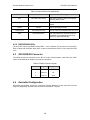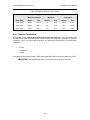
1
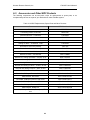
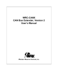
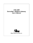
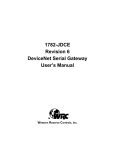
1782-JDC
DeviceNet/Serial Gateway
User’s Manual
Western Reserve Controls, Inc.
Western Reserve Controls, Inc.
1782-JDC User’s Manual
Although every effort has been made to insure the accuracy of this document, all information is
subject to change without notice. Western Reserve Controls, Inc. assumes no liability for any
errors or omissions in this document or for direct, indirect, incidental or consequential damage
resulting from the use of this document.
Document 25.0
Rev 1.00
June 2000
Copyright © 2000 WRC
Western Reserve Controls, Inc.
1485 Exeter Road
Akron OH 44306
330-733-6662 (Phone)
330-733-6663 (FAX)
[email protected] (Email)
http://www.wrcakron.com (Web)
WRC is a trademark of Western Reserve Controls, Inc.
DeviceNet is a trademark of the Open DeviceNet Vendor Association (“ODVA”).
All other trademarks are property of their respective companies.
i
Western Reserve Controls, Inc.
1782-JDC User’s Manual
TABLE OF CONTENTS
1.
OVERVIEW ........................................................................................................................................................1
1.1
FEATURES ..........................................................................................................................................................2
1.2
DEVICENET SYSTEM ARCHITECTURE ................................................................................................................2
1.3
BASIC OPERATION .............................................................................................................................................2
1.3.1 Polled I/O .....................................................................................................................................................3
1.3.2 Explicit Messages .........................................................................................................................................3
1.3.3 Cyclic Input Message (not currently implemented)......................................................................................3
1.3.4 Change-of-State, or COS (not currently implemented) ................................................................................3
1.4
DEFAULT DEVICE CONFIGURATION ...................................................................................................................3
1.5
EDS...................................................................................................................................................................3
2.
2.1
2.2
2.3
2.4
2.5
2.6
QUICK START ...................................................................................................................................................4
HOW TO INSTALL AND DEVICENET ESTABLISH COMMUNICATIONS ...................................................................4
HOW TO CHANGE THE NODE ADDRESS..............................................................................................................4
HOW TO CHANGE THE BAUD RATE ....................................................................................................................4
HOW TO INSTALL SERIAL NETWORK..................................................................................................................5
HOW TO READ SERIAL DEVICE INPUT DATA......................................................................................................5
HOW TO WRITE SERIAL OUTPUT DATA .............................................................................................................5
3.
GENERAL SPECIFICATIONS ........................................................................................................................7
4.
HARDWARE INSTALLATION AND SET-UP...............................................................................................9
4.1
OVERVIEW .........................................................................................................................................................9
4.2
LED OPERATION ...............................................................................................................................................9
4.2.1 DeviceNet LED’s..........................................................................................................................................9
4.2.2 RS232/RS485 LED’s ..................................................................................................................................10
4.3
RS232/RS485 CONNECTOR ............................................................................................................................10
4.4
DEVICENET CONFIGURATION ..........................................................................................................................10
4.4.1 Network Termination..................................................................................................................................11
4.4.2 DeviceNet Connection Wiring ....................................................................................................................12
4.5
JDC PRODUCT CONFIGURATION ......................................................................................................................13
A.
APPENDIX ........................................................................................................................................................15
A.1
1782-JDC DEVICENET PROFILE ......................................................................................................................15
A.2
SERIAL I/O OBJECT POLLED DATA FORMATS ..................................................................................................16
A.2.1
Attributes and Services...........................................................................................................................16
A.3
IDENTITY OBJECT, CLASS 0X01.......................................................................................................................19
A.4
PARAMETER OBJECT, CLASS 0X0F (15) ..........................................................................................................20
A.4.1
Attributes and Services...........................................................................................................................20
A.5
ACCESSORIES AND OTHER WRC PRODUCTS ...................................................................................................23
ii
Western Reserve Controls, Inc.
1782-JDC User’s Manual
TABLE OF FIGURES
FIGURE 1-1 1782-JDC ....................................................................................................................................................1
FIGURE 4-1 1781-JDC MECHANICAL OUTLINE DRAWING.............................................................................................12
FIGURE 4-2 DEVICENET CABLE CONNECTOR ................................................................................................................12
LIST OF TABLES
TABLE 1-1 I/O MESSAGE TYPES .....................................................................................................................................3
TABLE 2-1 BAUD RATE SELECTION ................................................................................................................................5
TABLE 4-1 MODULE STATUS LED (LABELED MS) .........................................................................................................9
TABLE 4-2 NETWORK STATUS LED (LABELED NS)......................................................................................................10
TABLE 4-3 RS485 CONNECTOR SIGNALS .....................................................................................................................10
TABLE 4-4 MAXIMUM NETWORK CABLE LENGTHS ......................................................................................................11
TABLE 4-5 JDC PARAMETER INSTANCES .....................................................................................................................13
TABLE A-1 DEVICENET OBJECTS .................................................................................................................................15
TABLE A-2 POLL PRODUCE DATA (ASCII RECEIVE STRING) .......................................................................................16
TABLE A-3 POLL CONSUME DATA (ASCII TRANSMIT STRING)....................................................................................16
TABLE A-4 SERIAL I/O CLASS ATTRIBUTES .................................................................................................................17
TABLE A-5 SERIAL I/O INSTANCE ATTRIBUTES ............................................................................................................17
TABLE A-6 SERIAL I/O COMMON SERVICES .................................................................................................................17
TABLE A-7 IDENTITY OBJECT CLASS ATTRIBUTES .......................................................................................................19
TABLE A-8 IDENTITY OBJECT INSTANCE ATTRIBUTES .................................................................................................19
TABLE A-9 IDENTITY OBJECT COMMON SERVICES ......................................................................................................19
TABLE A-10 PARAMETER CLASS ATTRIBUTES .............................................................................................................20
TABLE A-11 PARAMETER INSTANCE ATTRIBUTES ........................................................................................................20
TABLE A-12 PARAMETER COMMON SERVICES .............................................................................................................21
TABLE A-13 JDC PARAMETER INSTANCES (CLASS 15, $0F HEX) ................................................................................21
TABLE A-14 WRC REPLACEMENTS, SPARE PARTS AND OTHER PRODUCTS.................................................................23
iii
Western Reserve Controls, Inc.
1782-JDC User’s Manual
1. Overview
The 1782-JDC is a family of DeviceNet-to-serial link communications gateways that provide a
flexible DeviceNet interface to a wide variety of ASCII devices. The JDC allows the user to easily
and conveniently connect and integrate a peripheral products with either RS232 or RS485 serial
ports into a DeviceNet system.
Using the JDC you may communicate with the connected peripheral devices in the same fashion
as the other DeviceNet products in the system. Data may be read/written using either I/O polling
or explicit messaging. Typically real-time data is read and written as I/O by the DeviceNet Master
via Polled I/O and parameters are read and written with the Explicit Messaging technique.
The 1782-JDC is defined as a Communications Adapter device on the DeviceNet system. It has a
3-pin plug connector for connection to a RS232 or RS485 interface port on your device and a 5pin pluggable DeviceNet connector for connections to the DeviceNet network. Baud rate selection
is done automatically by the device when it is powered up on a network. The 1782-JDC has one
assigned DeviceNet address which is set by a 6-position DIP switch on the unit. Other JDC
parameters are software-configurable and are changed from their default values by third-party
DeviceNet configuration tools. Each 1782-JDC has 2 standard green/red DeviceNet LED’s for
module status and network status and two green LED’s to indicate RS485 transmit and receive
activity.
The RS232 version may be used for point-to-point connection to a single serial device. The
RS485 version may be connected in a point-to-point fashion to single device, or to multiple
devices in the standard RS485 convention.
The JDC is a general purpose gateway that is completely device-independent. The JDC does not
interpret the data being transmitted across it, and so the transferred messages may contain data
of any nature or definition. This allows you to use the same device for a wide variety of DeviceNetserial interface applications.
Figure 1-1 1782-JDC
1
Western Reserve Controls, Inc.
1.1
1782-JDC User’s Manual
Features
The 1782-JDC has the following features:
•
Translates messages and data between DeviceNet and a serial peripheral device
•
ODVA Conformance tested to DeviceNet Spec 2.0
•
Defined as a DeviceNet Communications Device Profile 12 (0x0C)
•
Autobaud operation
•
Polled I/O and Explicit Messaging
•
Software Configurable Parameters for serial port operation
•
Address selection via DIP switches
•
DIN rail mount
•
Pluggable 5-pin DeviceNet connection
•
Pluggable RS485 3-pin connection
•
2 standard DeviceNet module and network status LED’s
•
2 serial transmit and receive LED’s
•
Powered from DeviceNet 11-25 Vdc network power
•
ASCII string length up to 255 bytes
•
Serial port baud rate up to 38.4k baud
•
Optional isolated RS485 interface
1.2
DeviceNet System Architecture
A DeviceNet network is a distributed I/O system that may contain many different products from
several different vendors. Products may be configured uniformly, as clusters or as distributed
clusters. Up to 64 devices, including the master, may be attached to a single DeviceNet network.
Any of these, except the master, may be a JDC. A typical system will include a master, such as a
PLC or industrial PC, and multiple slave devices, including a 1782-JDC with connected peripheral
devices.
1.3
Basic Operation
The JDC operates as the DeviceNet front-end to the serial device(s). Connecting the JDC to a
single device, that device can then be assigned by the system implementer to one specific
master. The DeviceNet Master can receive and send data to and from the 1782-JDC via the
methods described in this section. It formats and sends the data to the device and likewise
accepts responses from the device, which are reformatted and passed back to the DeviceNet
system as required.
The JDC has one DeviceNet address. All DeviceNet messages to the JDC itself (to read / write its
internal data) are sent to this address. All DeviceNet messages to and from the serial device are
sent to the JDC DeviceNet assembly objects using poll commands.
The JDC Parameter Object allows you to define the specific operation of each JDC. These
parameters include all the set-up required for the serial comm. link.
The following chart defines the various messaging methods used for “typical” data types at your
serial device.
2
Western Reserve Controls, Inc.
1782-JDC User’s Manual
Table 1-1 I/O Message Types
Typical Data
Polled
Commands
√
Status
√
Cyclic
Bit-Strobe
Change-of-State
Parameters
Explicit Message
√
The following sections describe how the data is accessed.
1.3.1 Polled I/O
The DeviceNet Master uses the JDC’s predefined polled IO connection to send input and output
data to the JDC. The input data to the JDC has a one byte record number and up to 125
additional bytes of transmit data. When a poll is received and the record has changed since the
last poll was sent, the JDC sends the associated transmit data out the serial port to the remote
ASCII device. When the JDC receives serial data from a device on the serial link, the poll
response data to the Master contains a one byte record number, then a one byte status number
that reflects errors or events on the bus and up to 126 bytes of received data. The record number
is incremented in the poll response when new data is received on the serial link. The status byte is
zero if no errors occurred.
1.3.2 Explicit Messages
As mentioned explicit messages are typically used to read and write configuration data. This data
allows the JDC to change its internal operating parameters such as baudrate and parity. The JDC
does not allow for direct communication to the serial ports using explicit messaging.
1.3.3 Cyclic Input Message (not currently implemented)
Cyclic I/O is the function by which a slave device sends its input data to the master at a specific
time period without the host explicitly requesting it. When the specified time interval (defined by
you) elapses, the user-specified input data are transmitted to the master. This data may or may
not be the same as with a poll response.
1.3.4 Change-of-State, or COS (not currently implemented)
COS I/O is the function by which a slave device sends its input data to the master when defined
input data changes without the host explicitly requesting it. In the case of a serial device, this may
occur when a new message is asynchronously received from the serial device. This data may or
may not be the same as with a poll response.
1.4
Default Device Configuration
The 1782-JDC DeviceNet address is read from the switches and is set to 63 at the factory. All
other parameters are software settable. The default settings for the 1782-JDC are provided in the
discussion of the Parameter Object.
1.5
EDS
An EDS (Electronic Data Sheet), which describes the various parameters of the 1782-JDC, is
shipped with your device or is available on WRC’s web site: http://www.wrcakron.com/
3
Western Reserve Controls, Inc.
1782-JDC User’s Manual
2. Quick Start
To quickly and easily install your 1782-JDC in your DeviceNet system, follow the instructions
below. For more details, see Section 4.
2.1
How to Install and DeviceNet Establish Communications
1. Connect your DeviceNet network cable to a 5-pin female (Phoenix-type) plug according to
DeviceNet cable wiring specifications
2. Make sure that the DeviceNet network is terminated properly.
3. The JDC Node Address (MacID) is set to 63 at the factory. Make sure no other device on
the network is set to 63, or change the JDC address to one that is not currently used (see
below).
4. The JDC baud rate is set to Autobaud operation at the factory. See below to change it to a
fixed baud rate if desired.
5. Make sure that there is power on the DeviceNet network and plug the cable into the 1782JDC.
6. The 1782-JDC will undergo its initialization sequence, flashing both LED’s red and green.
After approximately 5 seconds, the Module Status LED (labeled “MS”) will go on solid
green and network LED will flash green.
7. The green Network Status LED (labeled “NS”) will go on solid after the Master recognizes
the unit on the link and allocates the connection (initiates communications).
8. The 1782-JDC is now operating on the network.
2.2
How to Change the Node Address
1. Set the 6-position DIP switch to the binary number representing the desired Node
Address, 0-63. (Note: Address 0 is often reserved for a Master device.)
2. Power cycle the unit by unplugging and reconnecting the DeviceNet cable.
NOTE: The new address will not become effective until the unit is power cycled or a
Reset command is received from the Master.
2.3
How to Change the Baud Rate
1. The Baud Rate is set to autobaud at the factory.
2. To change the baud rate, set DeviceNet Class (3), Instance 1, attribute 2, to the required
baud rate value shown in table 3-1.
4
Western Reserve Controls, Inc.
1782-JDC User’s Manual
Table 2-1 Baud Rate Selection
Baud Rate Value
Baud Rate
0
125k
1
250k
2
500k
3
Autobaud
NOTE: If you change the baudrate, the new baudrate will not become effective until the
unit is power cycled or a reset command is received by the Identity Object (Class 1,
Instance 0, reset).
2.4
How to Install Serial Network
1. The communication between your serial device(s) and the 1782-JDC is an RS232 3-wire
or RS-485 2-wire differential network.
2. Connect an appropriate cable to your device.
3. Connect the other end of the cable to the JDC using the 3-point terminal plug provided.
Note the terminal markings on the JDC case. See Error! Reference source not
found.below.
4. Turn on power to the serial device and the JDC.
5. Set up the poll input and output data fields to the required size in your Master’s scan
table. This should be no larger than the poll response for the 1782-JDC (The default is
16). If more than 16 bytes are required, set the Parameter Class (15 or hex $0F),
Instance 5 and 6, Attribute 1 to the required size (See Table 5-5).
2.5
How to Read Serial Device Input Data
1. Set up the poll input data field to be 16 bytes in your Master’s scan table. This should be
no larger than the poll response size set for the 1782-JDC. (The default is 16)
2. Perform an idle poll command to the JDC.
st
3. The JDC will return the data in its serial input data buffer, plus 2 additional bytes. The 1
byte of the data field returned will be a “record number”, which will be incremented by the
nd
JDC each time a new record is received from the serial device. The 2 byte contains the
status. The bytes following these will be the exact ASCII data received from the ASCII
device in ASCII format.
2.6
How to Write Serial Output Data
1. Set up the poll output data field to be 16 bytes in your Master’s scan table. This should be
no larger than the poll response size selected for the 1782-JDC (The default is 16).
2. Enter the ASCII data to be transmitted to your serial device in the appropriate buffer in
your scanner. This data field should include all data, including terminating characters or
bytes, that are to be sent to your device. Additionally, the first byte of the field must be a
5
Western Reserve Controls, Inc.
1782-JDC User’s Manual
“record number”, which the host application must increment each time a new record is
sent to that specific serial device. The bytes following this will be the ASCII data being
sent to the ASCII device.
3. Perform a poll command to the JDC. ASCII data will be sent to the JDC in the data bytes
immediately following the record number.
4. If any data is in the receive buffer in the JDC when the poll command is sent, the received
data will be returned as a poll response. (If the sequence number is the same as the
previous response, a new string has not yet been received by the JDC.)
6
Western Reserve Controls, Inc.
1782-JDC User’s Manual
3. General Specifications
Product:
1782-JDC Device-Serial Gateway
Description:
Communications gateway between a serial capable device over
an RS232 or RS485 interface and a DeviceNet network.
Device Type:
Communications Adapter, 0x0C hex, (12)
Device Profile:
Identity Object
Message Router Object
DeviceNet Object
Connection Object
Parameter Object
Serial I/O Object (vendor-specific)
Product Revision:
1.01
DeviceNet Conformance:
Designed to conform to the ODVA DeviceNet Specification
Volume I and II, Version 2.0.
DeviceNet Communications:
Predefined Master/Slave Connection Set, Group 2 Only Server
DeviceNet:
Baud rate selection:
Autobaud operation (default)
Fixed baud (software selectable) – 125k, 250k and 500k baud
Address selection:
Address number 0 to 63, switch selectable (default = 63)
Cable Connection:
JDC: 5-pin pluggable header (male)
Phoenix Contact MSTBA 2.5/5-G-5.08/AU or equivalent
DeviceNet Cable: 5-contact plug (female contacts)
Phoenix Contact MSTB 2.5/5-ST-5.08/AU or
(included)
Status Indicators:
equivalent
Module Status: green/red bi-color LED
Network Status: green/red bi-color LED
Serial port:
Baud rate:
300, 600, 1200, 2400, 4800, 9600, 19.2k, 38.4k
baud (software selectable)
Parity:
Odd/even/none (software selectable)
Data bits:
7 or 8 (software selectable)
Cable Connection:
JDC: 3-pin pluggable header (male)
Phoenix Contact MSTBA 2.5/3-G-5.08/AU or equivalent
Serial Cable: 3-contact plug (female contacts)
Phoenix Contact MSTB 2.5/3-ST-5.08/AU
(included)
7
or
equivalent
Western Reserve Controls, Inc.
1782-JDC User’s Manual
Status Indicators:
Transmit Active: green LED
Receive Active: green LED
Network Isolation:
2500V (optional)
Max Power:
1.75 watts: 160 mA @ 11 Vdc - 70 mA @ 25 Vdc unregulated
power supply
Mounting:
DIN rail mount, EN 50022
Size:
•
•
•
Depth: 3.54” (90 mm)
Width: 0.98” (25 mm)
Height: 3.11” (79 mm)
Operating Temp:
0-70 ºC
Humidity:
0-95% RH, non-condensing
8
Western Reserve Controls, Inc.
1782-JDC User’s Manual
4. Hardware Installation and Set-Up
4.1
Overview
The JDC is mounted on an EN50022 DIN rail.
The JDC contains two LED’s to indicate the status of the device and the status of the network.
The device can be connected to the main DeviceNet trunk line or to a drop line via a 5-pin female
plug-style connector. It also has two green LED’s to indicate the presence of activity on the RS485
transmit and receive lines.
All power for the JDC is derived from the DeviceNet power.
4.2
LED Operation
4.2.1 DeviceNet LED’s
A JDC Multiplexer has two LED’s that provide visual status information to the user about the
product and the DeviceNet network. See Tables 5-1 and 5-2 that follow below for how to interpret
LED status indications.
Table 4-1 Module Status LED (labeled MS)
LED State
Module Status
Meaning
OFF
No Power
Green
Device Operational
JDC is operating normally.
Flashing Green
Device in Standby
JDC needs commissioning.
Flashing Red
Minor Fault
Red
Unrecoverable Fault
JDC may need replaced.
Flashing Red/Green
Device Self-Testing
JDC is in self-test mode.
There is no power through DeviceNet.
Recoverable fault.
9
Western Reserve Controls, Inc.
1782-JDC User’s Manual
Table 4-2 Network Status LED (labeled NS)
LED State
Module Status
Meaning
OFF
No Power / Not on-line
JDC has no power or has not completed
the Dup_MAC_ID test.
Flashing Green
On-line, not connected
JDC is on-line but is not allocated to a
Master.
Green
On-line
Flashing Red
Connection time-out
Red
Critical link failure
JDC is operating normally.
One or more I/O connections are timed out.
JDC has detected an error that makes it
incapable of communicating on the link.
(Bus off or Duplicate MAC ID).
4.2.2 RS232/RS485 LED’s
The JDC also has two (2) RS485 activity LED’s – one for transmit (TX) and one for receive (RX).
Each of these will illuminate when there is data communications active on the respective data
lines.
4.3
RS232/RS485 Connector
The ASCII devices are connected to the JDC via 3-wire communications cable. See your ASCII
device’s User Manual for details on the proper connections.
Table 4-3 RS485 Connector Signals
4.4
Pin #
Signal
Designator
1
Transmit
Tx
2
Receive
Rx
3
Ground
Gnd
DeviceNet Configuration
DeviceNet specifications provide for a maximum network distances for the main trunk line and
drop lines, depending upon the baud rate used on the network. They are:
10
Western Reserve Controls, Inc.
1782-JDC User’s Manual
Table 4-4 Maximum Network Cable Lengths
Trunk Line Length
Drop Length
Maximum Distance
Maximum
Cumulative
Baud Rate
Meters
Feet
Meters
Feet
Meters
Feet
125k baud
500 m
1640 ft
6m
20 ft
156 m
512 ft.
250k baud
250 m
820 ft
6m
20 ft
78 m
256 ft.
500k baud
100 m
328 ft
6m
20 ft
39 m
128 ft.
4.4.1 Network Termination
A DeviceNet system must be terminated at each end of the trunk line. The host controller and
the last JDC or other DeviceNet device on the network must always be terminated to eliminate
reflections, even if only two nodes are present. The DeviceNet specifications for the terminating
resistor are:
•
121 ohm
•
1% metal film
•
1/4 Watt
An appropriate terminating resistor, WRC part number RM121DN, may be purchased from WRC.
IMPORTANT: Per the DeviceNet spec -- do not terminate devices on drop lines.
11
Western Reserve Controls, Inc.
1782-JDC User’s Manual
0.984 (25)
3.540 (89.9)
0.394
(10)
0
0
4
0
0
32
36=ADDR
DEVICENET
ASCII
CONVERTER
S+
SG -
S-
GND
G
1
0
0
8
0
0
9=ADDR
A
D
D
R
E
S
S
1782-JDC
ADDRESS 1
SELECT 2
4
8
1=LEFT 16
32
0=RIGHT 63=ADDR
SG+
V+
CAN_H
MS
N/C
NS
CAN_L
V-
2.920 (74.2)
0.160 (4.1)
Figure 4-1 1781-JDC Mechanical Outline drawing
4.4.2 DeviceNet Connection Wiring
The JDC uses a 5-pin plug-style DeviceNet connector, which has male pins.
Figure 4-2 DeviceNet cable connector
12
3.11(79))
Western Reserve Controls, Inc.
4.5
1782-JDC User’s Manual
JDC Product Configuration
Table 4-5 JDC Parameter Instances
Parameter
Param.
Instance
Description
Parameter Choices
Default
Setting
Default
Value
Number of
Data Bits
1
ASCII data frame size
7 or 8
8
8
Serial Baud
Rate
2
RS232/ RS485 communications
speed
0 = 9600, 1 = 300, 2 =
600, 3 = 1200, 4 =
2400, 5 = 4800, 6 =
19.2k, 7 = 38.4k
9600
0
End-of-Text
Character
3
Character which identifies the
end of the data string
Any valid standard
ASCII character (0 –
127)
Carriage
return
13 (dec.)
Parity
4
Character frame parity operation
0 = None, 1 = odd, 2 =
even
None
0
Max Number
of Receive
Chars
5
Maximum number of characters
the JDC expects to receive into
its ASCII port from the serial
device
0 – 255
16
16
Max Number
of Transmit
Chars
6
Maximum number of characters
the JDC expects to transmit out
its serial port to the serial device
0 – 255
16
16
0x0D
1.
Number of Data Bits: The number of data bits in the character frame. Values of
7 and 8 are valid.
>> Note: The JDB always uses one Start Bit and one Stop Bit .
2.
Baud Rate: The baud rate of the ASCII channels. Baud rates of 300, 600, 1200,
2400, 4800, 9600, 19.2k and 38.4k baud are valid.
3.
End-of-Text Character: The (printable or non-printable) byte character (value of
0-255) which signifies that the last character in a string of ASCII characters has
been reached. The JDB will not transmit to the device or return to the Master any
additional characters after the EOT character, or any characters in the string after
the maximum character count is reached.
4.
Parity: Designates the use of Odd, Even or No parity for the character frames.
5.
Maximum Number of ASCII Input Characters: The maximum number of ASCII
characters expected to be input from the serial device connected to this port. The
end-of-string, or end-of-text, character is included in this count. (A “0” implies the
port does not receive data from the external device or that no device exists.)
13
Western Reserve Controls, Inc.
1782-JDC User’s Manual
6.
Maximum Number of ASCII Output Characters: The maximum number of
ASCII characters that will be sent from the host to the serial device connected to
this port. The end-of-string, or end-of-text, character is included in this count. (A
“0” implies the port does not output data to the external device or that no device
exists.)
7.
COS Active Enable: Allows a new input from the peripheral serial devices to
trigger a change-of state message on the DeviceNet link. FUTURE. NOT
CURRENTLY IMPLEMENTED.
8.
DeviceNet Baud Rate: Allows a selection of baud rates on the DeviceNet link.
The current product is autobaud only. FUTURE. NOT CURRENTLY
IMPLEMENTED.
14
Western Reserve Controls, Inc.
1782-JDC User’s Manual
A.Appendix
A.1
1782-JDC DeviceNet Profile
This section describes the DeviceNet Objects present in the JDC. The JDC conforms to a Type
12, Communications Adapter Device.
Table A-1 DeviceNet Objects
Object
DeviceNet Object
Class
# of Instances
Identity
1 (01 hex)
1
Message Router
2 (02 hex)
1
DeviceNet
3 (03 hex)
1
Connection
5 (05 hex)
2 (Explicit Msg, Polled I/O)
Parameter
15 (0F hex)
6
Serial ASCII Input/Output
100 (64 hex)
1
15
Western Reserve Controls, Inc.
A.2
1782-JDC User’s Manual
Serial I/O Object Polled Data Formats
Table A-2 Poll Produce Data (ASCII Receive String)
Byte
0
1
2
3
•
•
•
X
X+1
•
•
Max Rec
Char + 1
Characte
r
Record #
Description
Status
st
1 Char
nd
2 Char
Record Counter, Integer value 1 – 255
0 = Initialized State (counter value rolls over from 255 to 1, skipping 0)
Status / Error Value
ASCII Character
ASCII Character
Last Char
EOF A
ASCII Character
End-of-Text (Record) Character
Any
Undefined (present if characters received is less than Max Receive Chars value)
Table A-3 Poll Consume Data (ASCII Transmit String)
Byte
0
1
2
3
•
•
•
X
x+1
•
•
Max Tx
Length –
1
Max Tx
Length
Characte
r
Record #,
Port A
st
1 Char
nd
2 Char
rd
3 Char
Description
Record Counter, Integer value 1 – 255
0 = Initialized State (counter value rolls over from 255 to 1, skipping 0)
ASCII Character
ASCII Character
ASCII Character
Last Char
EOF A
ASCII Character
End-of-File (Record) Character
Any
Undefined
Any
Undefined
(last char in this record transmitted to Master)
A.2.1 Attributes and Services
Following are the Class Attributes, Instance Attributes and Services are supported by the
JDXX for the Serial I/O Point Object.
16
Western Reserve Controls, Inc.
1782-JDC User’s Manual
Table A-4 Serial I/O Class Attributes
Attribute
ID
Access
Rule
Name
DeviceNe
t Data
Type
UINT
UINT
1
2
Get
Get
Revision
Max Instance
6
Get
Max ID Number of
Class Attributes
UINT
7
Get
Max ID Number of
Instance Attributes
UINT
Description of Attribute
Value
Revision of this object
Maximum instance number of an
object currently created in this
class level of the JDXX.
The attribute ID number of the
last class attribute of the class
definition implemented in the
JDXX.
The attribute ID number of the
last instance attribute of the
class definition implemented in
the JDXX.
xx
xx
7
xx
Table A-5 Serial I/O Instance Attributes
Attribute
ID
Access
Rule
Name
1
Get
2
Get
Number
attributes
Attribute list
of
3
Get
Receive Data
4
Get/Set
Transmit Data
5
6
7
8
9
10
11
12
13
14
15
16
17
18
19
20
21
Get
Get
Get
Get
Get
Set
Set
Get/Set
Get/Set
Get/Set
Get/Set
Get/Set
Get/Set
Get/Set
Get/Set
Get/Set
Get/Set
Status
Produce path
Consume path
Baud Rate
Parity
Data Size
Stop Bits
Flow Control
Receive Count
Transmit Count
Max Receive Size
Data Format
Block Mode
Receive Delimiter
Pad Char
Max Transmit Size
Idle String
22
Get/Set
Fault String
DeviceNe
t Data
Type
USINT
Array of
USINT
Array of
BYTES or
SHORT_
STRING
Array of
BYTES or
SHORT_
STRING
USINT
EPATH
EPATH
USINT
USINT
USINT
USINT
USINT
USINT
USINT
USINT
USINT
USINT
USINT
CHAR
USINT
SHORT_
STRING
SHORT_
STRING
Description of Attribute
Number of attributes supported
List of attributes supported by
the point
ASCII input string from the
external serial device
ASCII output string
external serial device
Table A-6 Serial I/O Common Services
17
Value
to
the
1 length
the
number
bytes
1 length
the
number
bytes
byte plus
specified
of data
byte plus
specified
of data
Western Reserve Controls, Inc.
Class
Instance
1782-JDC User’s Manual
Service
Code
O5 hex
OE hex
Service Name
No
Yes
Yes
Yes
Reset
Get_Attribute_Single
10 hex
No
Yes
Set_Attribute_Single
18
Description of Service
Returns the contents of the
specified attribute.
Modifies an attribute value.
Western Reserve Controls, Inc.
A.3
1782-JDC User’s Manual
Identity Object, Class 0x01
Table A-7 Identity Object Class Attributes
Attribute
ID
Access
Rule
1
2
Get
Get
6
Get
7
Get
Name
Revision
Max.
Object
Instance
Max.
Class
Attribute ID
Max.
Instance
Attributes ID
DeviceNe
t Data
Type
UINT
UINT
UINT
UINT
Description of Attribute
Revision of this object
Maximum instance number of an
object currently
Attribute ID number of the last
class attribute of the class
definition implemented in the
device
Attribute ID number of the last
instance attribute of the class
definition implemented in the
device
Value
1
1
7
1
Table A-8 Identity Object Instance Attributes
Attribute
ID
Access
Rule
Name
1
Get
Vendor
DeviceNe
t Data
Type
UINT
2
Get
Device Type
UINT
3
Set
Product Code
UINT
4
Get
Revision
5
6
Get
Get
Major Revision
Minor Revision
Status
Serial Number
STRUCT
of:
USINT
USINT
WORD
UDINT
7
Get
Product Name
Description of Attribute
ODVA Vendor Number for this
product
ODVA Communications Device
Type
WRC Unique Product Code
Number
Revision of this device
Summary status of device
WRC Unique Device Serial
Number
ASCII Name of product
SHORT_
STRING
Value
9 = WRC
12. = 0C hex
701. = 2BD hex
xx
xx
xx
1782-JDC
Table A-9 Identity Object Common Services
Service
Code
O5 hex
Class
Instance
Service Name
Yes
Reset
OE hex
Yes
Yes
Get_Attribute_Single
10 hex
N/A
No
Set_Attribute_Single
19
Description of Service
Invokes the Reset Service for
the device.
Returns the contents of the
specified attribute.
Modifies an attribute value.
Western Reserve Controls, Inc.
A.4
1782-JDC User’s Manual
Parameter Object, Class 0x0F (15)
There are many configurable data parameters associated with your JDC. The JDC uses
a Parameter Object (a collection of these parameters) to assist you in reading and changing
configurable data.
A.4.1 Attributes and Services
Following are the Class Attributes, Instance Attributes and Services are supported by the JDC for
the Parameter Object.
Table A-10 Parameter Class Attributes
Attribute
ID
Access
Rule
Name
1
2
Get
Get
Revision
Max. Instance
8
Get
Parameter
descriptor
9
Get
Configuration
Assembly
Instance
class
DeviceNe
t Data
Type
UINT
UINT
WORD
UINT
Description of Attribute
Value
Revision of this object.
Maximum instance number of
the Parameter object
Bits that describe parameters.
Instance
Number
of
Configuration Assembly.
the
1
12
9 (supports parameter
instances, params are
stored in non-volatile
memory)
0. ????
Table A-11 Parameter Instance Attributes
Attribute
ID
Access
Rule
Stub
/Full
Name
1
Set
Parameter Value
2
Set
Link Path Size
3
Set
Link Path
4
5
6
Get
Get
Get
Descriptor
Data Type
Data Size
DeviceNe
t Data
Type
data type
specified
in
Descriptor
Data Type
and Data
Size.
USINT
ARRAY of
DeviceNet
path:
WORD
USINT
USINT
20
Description of Attribute
Value
Actual value of parameter. It can
be read from or written to. This
attribute is read-only if bit 4 of
Attribute 4 is TRUE.
Size of link path. If this is 0, then
no link is specified.
DeviceNet path to the object
from where this parameter’s
value is retrieved.
Description of parameter.
Data type code.
Number of bytes in Parameter
Value
Number of bytes.
Western Reserve Controls, Inc.
1782-JDC User’s Manual
Table A-12 Parameter Common Services
Service
Code
O5 hex
Class
Instance
Service Name
Yes
N/A
Reset
OE hex
Yes
Yes
Get_Attribute_Single
10 hex
Yes
Yes
Set_Attribute_Single
Description of Service
Resets all parameters to
“out-of-the-box” values.
Returns the contents of the
specified attribute.
Modifies an attribute value.
Table A-13 JDC Parameter Instances (Class 15, $0F hex)
Parameter
Param.
Instance
Description
Parameter Choices
Default
Setting
Default
Value
Number of
Data Bits
1
ASCII data frame size
7 or 8
8
8
Serial Baud
Rate
2
RS232/ RS485 communications
speed
0 = 9600, 1 = 300, 2 =
600, 3 = 1200, 4 =
2400, 5 = 4800, 6 =
19.2k, 7 = 38.4k
9600
0
End-of-Text
Character
3
Character which identifies the
end of the data string
Any valid standard
ASCII character (0 –
127)
Carriage
return
13 (dec.)
Parity
4
Character frame parity operation
0 = None, 1 = odd, 2 =
even
None
0
Max Number
of Receive
Chars
5
Maximum number of characters
the JDC expects to receive into
its ASCII port from the serial
device
0 – 255
16
16
Max Number
of Transmit
Chars
6
Maximum number of characters
the JDC expects to transmit out
its serial port to the serial device
0 – 255
16
16
0x0D
9.
Number of Data Bits: The number of data bits in the character frame. Values of
7 and 8 are valid.
>> Note: The JDB always uses one Start Bit and one Stop Bit .
10.
Baud Rate: The baud rate of the ASCII channels. Baud rates of 300, 600, 1200,
2400, 4800, 9600, 19.2 and 38.4k baud are valid.
11.
End-of-Text Character: The (printable or non-printable) byte character (value of
0-255) which signifies that the last character in a string of ASCII characters has
been reached. The JDB will not transmit to the device or return to the Master any
additional characters after the EOT character, or any characters in the string after
the maximum character count is reached.
12.
Parity: Designates the use of Odd, Even or No parity for the character frames.
21
Western Reserve Controls, Inc.
1782-JDC User’s Manual
13.
Maximum Number of ASCII Input Characters: The maximum number of ASCII
characters expected to be input from the serial device connected to this port. The
end-of-string, or end-of-text, character is included in this count. (A “0” implies the
port does not receive data from the external device or that no device exists.)
14.
Maximum Number of ASCII Output Characters: The maximum number of
ASCII characters that will be sent from the host to the serial device connected to
this port. The end-of-string, or end-of-text, character is included in this count. (A
“0” implies the port does not output data to the external device or that no device
exists.)
15.
COS Active Enable: Allows a new input from the peripheral serial devices to
trigger a change-of state message on the DeviceNet link. FUTURE. NOT
CURRENTLY IMPLEMENTED.
16.
DeviceNet Baud Rate: Allows a selection of baud rates on the DeviceNet link.
The current product is autobaud only. FUTURE. NOT CURRENTLY
IMPLEMENTED.
22
Western Reserve Controls, Inc.
A.5
1782-JDC User’s Manual
Accessories and Other WRC Products
The following components can be used with a Ajax for replacements or spare parts, or as
complementary devices as a part of your DeviceNet or other CAN-Bus system.
Table A-14 WRC Replacements, Spare Parts and Other Products
Part
WRC Part Number
DIN rail
WRC 50022
Terminating resistor, axial lead
RM121DN
Discrete I/O block – 4 channels
1782-JDB4
Discrete I/O block – 8 channels
1781-JDB8
Analog Input block – 4 channels, 10-bit
1782-JDA4
Analog I/O block – 8 channels, 12-bit
1782-JDA8
DeviceNet to Serial I/O Gateway
1782-JDC
DeviceNet to Modbus Gateway
1782-JDM
Discrete I/O block – 24 channels
WRC1-JDB24
Discrete I/O block – 48 channels
WRC1-JDB48
Discrete I/O, Analog Input block – 24 DIO, 32 AI
WRC1-JDA/24
Discrete I/O, Analog Input block – 48 DIO, 32 AI
WRC1-JDA/48
Analog I/O block - 32 channels
WRC1-JDAIO
Discrete and Analog I/O block – 24 DIO, 32 AIO
WRC1-JDAIO/24
Discrete and Analog I/O block – 48IO, 32 AIO
WRC1-JDAIO/48
Discrete I/O block – 8 DIs, 8 DOs, 4 AIs
W5-JDB16x
DeviceNet, CANopen Extender, DIN mount
WRC-CANX-DIN-DN
SDS Extender, DIN mount
WRC-CANX-DIN-SD
DeviceNet, CANopen Extender, DIN mount
WRC-CANX-DIN-C7
DeviceNet, CANopen Extender, NEMA box
WRC-CANX-NEM-AU
DeviceNet, CANopen Extender, NEMA box
WRC-CANX-NEM-DN
SDS Extender, NEMA box
WRC-CANX-NEM-SD
DeviceNet, CANopen Extender, Fiber Optic, NEMA
box
WRC-CANR-DF-DN
23