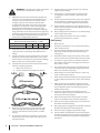
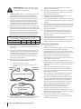
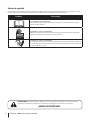
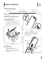
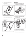
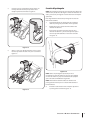
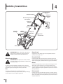
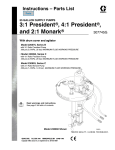
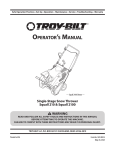
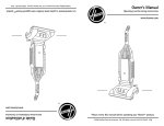
1
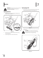
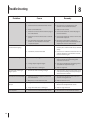
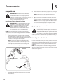
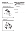
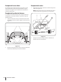
Safe Operation Practices • Set-Up • Operation • Maintenance • Service • Troubleshooting • Warranty Operator’s Manual Electric Snow Thrower — Flurry 1400 WARNING READ AND FOLLOW ALL SAFETY RULES AND INSTRUCTIONS IN THIS MANUAL BEFORE ATTEMPTING TO OPERATE THIS MACHINE. FAILURE TO COMPLY WITH THESE INSTRUCTIONS MAY RESULT IN PERSONAL INJURY. TROY-BILT LLC, P.O. BOX 361131 CLEVELAND, OHIO 44136-0019 Form No. 769-08074 (March 21, 2012) 1 To The Owner Thank You Thank you for purchasing a Troy-Bilt Electric Snow Thrower. It was carefully engineered to provide excellent performance when properly operated and maintained. Please read this entire manual prior to operating the equipment. It instructs you how to safely and easily set up, operate and maintain your machine. Please be sure that you, and any other persons who will operate the machine, carefully follow the recommended safety practices at all times. Failure to do so could result in personal injury or property damage. If you have any problems or questions concerning the machine, phone a authorized Troy-Bilt service dealer or contact us directly. Troy-Bilt’s Customer Support telephone numbers, website address and mailing address can be found on this page. We want to ensure your complete satisfaction at all times. Throughout this manual, all references to right and left side of the machine are observed from the operating position All information in this manual is relative to the most recent product information available at the time of printing. Review this manual frequently to familiarize yourself with the machine, its features and operation. Please be aware that this Operator’s Manual may cover a range of product specifications for various models. Characteristics and features discussed and/or illustrated in this manual may not be applicable to all models. We reserve the right to change product specifications, designs and equipment without notice and without incurring obligation. Table of Contents Safe Operation Practices......................................... 3 Assembly & Set-Up................................................... 7 Controls & Features.................................................10 Operation.................................................................11 Maintenance & Adjustment..................................13 Service......................................................................14 Troubleshooting......................................................16 Replacement Parts..................................................17 Warranty...................................................Back Cover Record Product Information Model Number Before setting up and operating your new equipment, please locate the model plate on the equipment and record the information in the provided area to the right. You can locate the model plate by standing on the left side of the snow thrower and looking at the belt cover. This information will be necessary, should you seek technical support via our web site, Customer Support Department, or with a local authorized service dealer. Serial Number Customer Support Please do NOT return the machine to the retailer or dealer without first contacting the Customer Support Department. If you have difficulty assembling this product or have any questions regarding the controls, operation, or maintenance of this machine, you can seek help from the experts. Choose from the options below: ◊ Visit us on the web at www.troybilt.com See How-to Maintenance and Parts Installation Videos at www.troybilt.com/tutorials 3 ◊ Call a Customer Support Representative at (800) 828-5500 or (330) 558-7220 ◊ Write to Troy-Bilt LLC • P.O. Box 361131 • Cleveland, OH • 44136-0019 Important Safe Operation Practices 2 WARNING: This symbol points out important safety instructions which, if not followed, could endanger the personal safety and/or property of yourself and others. Read and follow all instructions in this manual before attempting to operate this machine. Failure to comply with these instructions may result in personal injury. When you see this symbol, HEED ITS WARNING! DANGER: This machine was built to be operated according to the safe operation practices in this manual. As with any type of power equipment, carelessness or error on the part of the operator can result in serious injury. This machine is capable of amputating fingers, hands, toes and feet and throwing objects. Failure to observe the following safety instructions could result in serious injury or death. WARNING: When using electric snow throwers, basic safety precautions should always be followed to reduce the risk of fire, electric shock, and personal injury. These basic precautions include the following. READ ALL INSTRUCTIONS Double Insulated Snow Thrower Double insulation is a concept in the safety of electric snow throwers, which eliminates the need for the usual three-wire grounded power cord and grounded power supply system. Wherever there is electric current in the snow thrower, there are two complete sets of insulation to protect the user. All exposed metal parts are isolated from the internal metal motor components with protecting insulation. Servicing of a snow thrower with double insulation requires extreme care and knowledge of the system and should be performed only by a qualified service technician. For repair service we suggest you take the snow thrower to your nearest authorized service dealer. Always use original equipment manufacturer’s (OEM) replacement parts when servicing. Before Operating 8. Make sure the auger will spin freely before using the unit. 1. Read the instructions carefully. Be familiar with the controls and proper use of the unit. 9. 2. Do not operate this unit when tired, ill or under the influence of alcohol, drugs or medication. Dress properly. Wear adequate winter outer garments. Wear heavy, long pants, boots, gloves and a long sleeve shirt. Do not wear loose clothing, jewelry, short pants, sandals or go barefoot. Secure hair above shoulder level. 3. Keep children and other bystanders away. All visitors should be kept a safe distance from work area. 10. 4. Children under the age of 15 must not use the unit; properly trained older teens may operate the unit with adult supervision. Wear footwear that doesn’t leak when operating the snow thrower and that will improve footing on slippery surfaces. Wear rubber boots. 11. Never attempt to make adjustments while the motor is running. 5. Inspect the unit before use. Replace damaged parts. Make sure all fasteners are in place and secure. Replace snow thrower parts that are cracked, chipped, or damaged in any way. 12. Let the motor and unit adjust to outdoor temperatures before starting to clear snow. 13. Always wear safety glasses/shields or goggles at all times during operation or while performing an adjustment or repair to protect eyes from foreign objects that may be thrown from the machine. 14. When servicing use only identical replacement parts. If cord is damaged or switch doesn’t work, have an authorized service dealer replace entire operator control assembly. 6. Exercise caution to avoid slipping or falling. 7. Thoroughly inspect the area where the snow thrower is to be used. Remove all doormats, sleds, boards, wires, debris, and other foreign objects which may be thrown by the snow thrower. 3 WARNING: To prevent electric shock use only with an extension cord suitable for outdoor use. 15. CORD SETS: Please see your dealer for the appropriated extension cord to use with this product. Make sure your cord set is in good condition, with a cord that is heavy enough to carry the current that your unit will draw. An undersized cord set will cause a drop in line voltage resulting in a loss of power, as well as overheating. The table shown above illustrates the correct size to use depending on the cord length and nameplate amperage rating. If in doubt, use the next heavier size line gauge. The smaller the gauge number, the heavier the cord. To prevent the cord from disconnecting from the unit, use the cord hook shown in the Operating Instructions. MINIMUM WIRE SIZE FOR EXTENSION CORDS FOR 120 VOLT APPLIANCES USING 10 - 12 AMPS Cord Length (ft.) Wire Size (AWG) 16 50 16 100 14 Keep the extension cord away from heat, oil, and sharp edges to prevent damage. 21. If the extension cord is damaged in any manner while it is plugged in, pull the extension cord from the wall receptacle. 22. Prevent any possible disconnection of the cord receptacle from the extension cord during operation by using the cord retainer and guide bar. Refer to the Set-Up section. 23. Avoid accidental starting. Don’t carry a plugged-in snow thrower with your finger on the switch. Be sure switch is off when plugging in the unit. 24. Always unplug the unit and allow it to cool before putting it into storage. Store indoors. 25. Always unplug the unit when not in use, and before performing any maintenance or repairs. While Operating 150 1. Walk, never run. 12 2. Be sure the snow thrower is not in contact with anything before starting the unit. 16. A data plate on your unit indicates the voltage used. Never connect the unit to an AC voltage that differs from this voltage. 3. Stay away from the discharge opening at all times. Keep face, hands, and feet away from concealed moving or rotating parts. 17. Inspect all extension cords and the unit power connection periodically. Look closely for deterioration, cuts or cracks in the insulation. Also inspect the connections for damage. Repair or replace the cords if any defects appear. 4. Be attentive when using the snow thrower, and stay alert for holes in the terrain and other hidden hazards or traffic. 5. Do not use on a gravel surface or crushed rock surfaces. Use extreme caution when crossing gravel/crushed rock drives, walks, or roads. 6. Clear snow from slopes by going up and down. Never go across the slope. Use caution when changing directions. Never clear snow from steep slopes. 7. Never attempt to use the snow thrower on a roof or any steep, inclined, slippery surfaces. 8. Never operate snow thrower without proper guards, plates or other safety protective devices in place, and in working order. 9. Never operate the snow thrower near glass enclosures, automobiles, trucks, window wells, dropoffs, etc. without proper adjustment of the snow discharge angle. Keep children and pets away. 10. Don’t force or overload the snow thrower. The snow thrower will perform at its best and safest when it is run at the rate for which it was designed. 11. Never operate the machine at high speeds on slippery surfaces. Look behind and use care when backing up. 12. Never direct discharge towards people or allow anyone in front of the unit while operating. 13. Wear safety glasses or goggles that are marked as meeting ANSI Z87.1 standards when operating this unit. 14. Use the unit only in daylight or good artificial light. 15. Avoid accidental starting. Remain in the starting position whenever starting the unit. The operator and unit must be in a stable position while starting. See Starting/Stopping Instructions. 18. 18. 19. 4 25 20. To prevent disconnection of snow thrower cord from the extension cord during operation, a. Make a knot as shown, or b. Use the cord retainer described in this manual When cleaning, inspecting or repairing the unit, make certain the auger and all moving parts have stopped. Disconnect the extension cord to prevent accidental starting. Do not abuse the extension cord. Never carry the snow thrower by the cord or yank on the cord to disconnect it from the receptacle. Section 2 — Important Safe Operation Practices 16. Use the right tool. Only use this tool for the purpose intended. 17. Do not overreach. Always keep proper footing and balance. 18. Always hold both hands on the upper handle when operating the unit. Keep a firm grip on upper handle. 19. Do not use the unit in the hand held position. Do not pick up the unit when it is powered and running. The unit is designed to travel on the ground. The lower lift handle is only provided to assist in picking up or carrying the unit when it is not plugged in. 20. Keep hands, face, and feet at a distance from all moving parts. Do not touch or try to stop the auger when it is rotating. 21. If the auger will not rotate freely due to frozen ice, thaw the unit thoroughly before attempting to operate it under power. 22. Keep the auger clear of debris. 29. If the unit should start to vibrate abnormally, stop the unit and check immediately for the cause. Vibration is generally a warning of trouble. 30. Stop the motor and unplug the unit whenever you leave the operating position, before unclogging the auger, and when making any repairs, adjustments, or inspections. 31. Never discharge snow onto public roads or near moving traffic. 32. Let the snow thrower run for a few minutes after clearing snow so moving parts do not freeze. 33. Use only original equipment manufacturer replacement parts and accessories for this unit. These are available from your authorized service dealer. Use of any unauthorized parts or accessories could lead to serious injury to the user or damage to the unit, and void your warranty. Other Safety Warnings 1. Be sure to secure the unit while transporting. 23. Never attempt to clear the auger with the motor running. Turn the motor off first and unplug the extension cord. 2. Store the unit in a dry area, locked up or up high to prevent unauthorized use or damage, out of the reach of children. 24. Keep clothing and body parts away from the auger. 3. 25. Do not operate the motor faster than the speed needed. Do not run the motor at high speed when not clearing snow. Never douse or squirt the unit with water or any other liquid. Keep handles dry, clean and free from debris. Clean after each use, see Cleaning and Storage instructions. 4. If the labels on the unit become defaced or start lifting off, contact your authorized service dealer. 5. Keep these instructions. Refer to them often and use them to instruct other users. If you loan someone this unit, also loan them these instructions. 6. Maintain snow throwers with care. Follow instructions for lubricating and changing accessories. 26. Always stop the motor when clearing snow is delayed or when walking from one location to another. 27. Disengage power to the auger when snow thrower is transported or not in use. 28. If the snowthrower strikes a foreign object, follow these steps a. Stop snowthrower. b. Release the Motor Control Lever. c. Unplug the Power Cord. d. Inspect for damage. e. Repair any damage before restarting and operating the snowthrower. SAVE THESE INSTRUCTIONS Section 2 — Important Safe Operation Practices 5 Safety Symbols This page depicts and describes safety symbols that may appear on this product. Read, understand, and follow all instructions on the machine before attempting to assemble and operate. Symbol Description READ THE OPERATOR’S MANUAL(S) Read, understand, and follow all instructions in the manual(s) before attempting to assemble and operate. WARNING— ROTATING BLADES Keep hands out of inlet and discharge openings while machine is running. There are rotating blades inside. WARNING— ROTATING AUGER Do not put hands or feet near rotating parts, in the auger/impeller housing or chute assembly. Contact with the rotating parts can amputate hands and feet. WARNING: Your Responsibility—Restrict the use of this power machine to persons who read, understand and follow the warnings and instructions in this manual and on the machine. SAVE THESE INSTRUCTIONS! 6 Section 2 — Important Safe Operation Practices 3 Assembly & Set-Up Contents of Carton • One Electric Snow Thrower • One Upper Handle • One Mid Handle • One Chute Assembly • One Electric Snow Thrower Operator’s Manual • One Product Registration Card NOTE: All references to the left and right side of the snow thrower are from the operator’s position behind the snow thrower. Handle Assembly 1. Install the strain reliever on the mid handle. See Figure 3-2. Tools Required for Assembly • Phillips Head Screwdriver Unpacking the Unit 1. Cut the corners of the carton and lay the sides flat on the ground. Remove all packing inserts. 2. Lift the upper handle and mid handle up and off the snow thrower. See Figure 3-1. Figure 3-2 NOTE: The flared area on the lower portion of the mid handle must face forward throughout the assembly. Figure 3-1 3. Make certain the carton has been completely emptied before discarding it. 7 2. Attach the upper handle to the mid handle using one carriage screw and handle knob on each side. See Figure 3-3. 5. Secure motor cord to cable guide. See Figure 3-5. NOTE: The motor cord runs behind the upper handle. NOTE: Make sure the cord is routed behind the handle assembly. Cable Guide Carriage Bolt Motor Cord Carriage Bolt Figure 3-5 Handle Knobs Chute Assembly Figure 3-3 3. Ensure that the cord retainer is on the mid handle’s crossbar. Refer to Figure 3-2. Place the mid and upper handles onto the lower handle. See Figure 3-4. 1. Remove the four screws securing the front cover to the auger housing. Remove the front cover and the chute. See Figure 3-6. Chute Assembly Front Cover Carriage Bolt Carriage Bolt Screw Handle Knobs Figure 3-4 4. 8 Insert wing knobs and carriage bolt and tighten to secure upper handle and mid handle to the lower handle. See Figure 3-4. Section 2— Assembly & Set-Up Figure 3-6 2. Remove the wing knob, bell washer and bolt from the left side of the chute. See Figure 3-7. 3. Pivot the upper chute upwards and over the lip and the top of the lower chute. 4. Reinstall the wing knob, bell washer and bolt. NOTE: When installing the bell washer the concave (or cupped) side of the washer must be installed facing the in towards the chute. Chute Assembly Front Cover Screw Figure 3-9 Connecting Extension Cord Figure 3-7 5. Install the chute in the auger housing with the handle facing towards the rear of the snow thrower. See Figure 3-8 NOTE: Do not plug your extension cord into the power source receptacle (outlet) prior to routing it through the cord retainer and connecting it to the snow thrower’s power cable. To properly route your extension cord through the strain reliever: 1. Approximately 14 to 16 inches from its end, crease your extension cord to form a tight loop. 2. Push the loop through the bottom of the strain reliever. 3. Position the loop over the clips found on the strain reliever and pull down until the cord fits snugly into the clip. Plug the snow thrower power cable into the extension cord. See Figure 3-10. Side View Figure 3-8 6. Re-install the front cover with the four screws removed in step 1. See Figure 3-9. Figure 3-10 NOTE: Use a UL-approved extension cord. A 100-foot, 14-gauge cord is recommended. A 50-foot, 16-gauge cord is acceptable. Refer to the small chart found in Safe Operation Practices. Section 2 — Assembly & Set-Up 9 4 Controls & Features Upper Handle Starter Button Motor Control Lever Circuit Breaker Reset Button Strain Reliever Power Cable Key Discharge Chute Chute Handle Lower Handle Middle Handle Auger WARNING! Read, understand, and follow all instructions and warnings on the machine and in this manual before operating. Motor Control Lever WARNING! The motor control lever is a safety device. Never attempt to bypass its operations. The motor control lever is located on the upper handle. The motor control lever engages and disengages the motor and auger. Key The key is a safety device. It must be fully inserted in order for the motor to start. Remove the key when the snow thrower is not in use. Chute Handle Rotate the discharge chute left or right using the chute handle. Strain Reliever The strain reliever is located on the middle handle of the snow thrower. The strain reliever reduces strain on the extension cord so that it does not come unplugged during operation. 11 Auger When engaged, the auger rotation draws snow into the auger housing and throws it out the discharge chute. Rubber paddles on the auger also aid in propelling the snow thrower as they come in contact with the pavement. Starter Button The starter button is located on the upper handle of the snow thrower. Engaging the motor control lever with the starter button pressed will start the snow thrower. Discharge Chute The pitch of the discharge chute controls the angle at which the snow is thrown. Loosen the wing knob on the side of the discharge chute before pivoting the discharge chute upward or downward. Retighten the knob once the desired position has been achieved. Circuit Breaker Reset Button The snow thrower is equipped with an circuit breaker reset button, located on the motor control. This button may pop out when too much strain is placed on the motor. Refer to the Maintenance & Adjustments Section to reset this button. 5 Operation Starting Motor 5. WARNING: Avoid accidental starting. Make sure you are in the operating position behind the snow thrower when using it. To avoid serious injury, the operator and unit should be in a stable position while starting. Connecting to an Electrical Power Source WARNING: This snow thrower should be operated While holding the starter button in, squeeze the motor control lever against the upper handle to start the motor and engage the auger. See Figure 5-1. NOTE: The snow thrower’s motor will NOT start if you fail to hold the starter button in while pivoting the motor control handle upward. 6. Release the red starter button. Stopping the Motor on a 15 or 20 AMP circuit. If you experience difficulty in starting with a standard 15 AMP fuse or circuit breaker, contact an authorized service dealer. Do not use a higher rated fuse or breaker without consulting your power company. WARNING: The auger continues to rotate for a few seconds after the motor is shut off. If motor does not come to a stop when the motor control handle is released, unplug the snow thrower from the outlet, and contact an authorized service dealer. NOTE: Connect your extension cord to the snow thrower as instructed in the Assembly & Set-Up section prior to plugging your extension cord into an electrical outlet. Release the motor control lever to stop the motor and auger. 1. Plug your extension cord into any convenient (indoor or outdoor) 120-volt, 60 hertz AC outlet or receptacle. Your snow thrower will operate satisfactorily on a circuit with a 15 ampere breaker. Lift up slightly on the handle to allow the rubber paddles on the auger to contact the pavement and propel the snow thrower forward. Pushing downward on the handle will raise the auger off the ground and stop the forward motion. NOTE: To avoid tripping circuit breakers, select an outlet on a circuit that is not overloaded. Do NOT select an outlet that is on a circuit hosting appliances such as a refrigerator. NOTE: Excessive upward pressure on the handle will result in premature wear on the rubber auger blades which are not covered by the warranty. Insert key. Refer to Figure 5-1. Adjusting the Chute Assembly 2. Motor Control Lever Starter Button Engaging the Drive The pitch of the chute assembly controls the angle at which the snow is thrown. 1. Loosen the wing knob found on the left side of the chute assembly and pivot the upper chute upward or downward to the desired pitch. Retighten the wing knob before operating the snow thrower. See Figure 5-2. Key Figure 5-1 3. Stand behind the snow thrower in the operating position. 4. Press the red starter button and hold it in. See Figure 5-1. NOTE: Starting the snow thrower’s motor also engages the auger. Figure 5-2 12 2. Position the chute assembly opening by using the chute handle to throw the snow in the desired direction. See Figure 5-3. Figure 5-3 Clearing a Clogged Discharge Chute WARNING! Never use your hands to clear a clogged chute assembly. Shut off motor, disconnect power cord, and remain behind handle until all moving parts have stopped before using a clean-out tool or stick to clear the chute assembly. Hand contact with the rotating auger inside the discharge chute is the most common cause of injury associated with snow throwers. Never use your hand to clean out the discharge chute. To clear the chute: 1. SHUT THE MOTOR OFF AND DISCONNECT POWER CORD! 2. Wait 10 seconds to be sure the auger has stopped rotating. 3. Always use a clean-out tool or stick, not your hands. Section 5 — Operation 13 6 Maintenance & Adjustments Resetting Circuit Breaker Maintenance This snow thrower is equipped with a circuit breaker to prevent overheating damage to the motor. Lubrication If the circuit breaker reset button pops out: Lubricate the pivot points on the motor control lever with a light oil once every season and before the snow thrower is put into storage at the end of the season. 1. Release the motor control lever and do NOT restart the snow thrower for at least one minute, allowing the electric motor time to cool. 2. Press the circuit breaker reset button (located on the switch assembly) inward to reset. See Figure 6-1. Off-Season Storage If the snow thrower will not be used for 30 days or longer, follow the instructions below. • Clean and lubricate snow thrower thoroughly as described in the lubrication instructions. • We do not recommend the use of a pressure washer or garden hose to clean your unit. • Make certain the power supply is disconnected. • Store snow thrower in a dry, clean area. Do not store next to corrosive materials, such as fertilizer. • Wipe extension cord to remove any foreign substance such as oil or stains. Replace extension cord if cut or damaged in any way. • Wind cord in a series of equal loops on each side of your hand to prevent snarling. Figure 6-1 14 7 Service WARNING: Unplug the snow thrower and remove the key to avoid unintended starting before servicing the snow thrower. Replacing Auger Belt 1. Unscrew the six screws securing the belt cover to the auger housing and remove the belt cover. See Figure 7-2. Replacing Skid Plate 1. Remove the three screws securing the skid plate to the auger housing. See Figure 7-1. Side View Figure 7-2 2. Figure 7-1 2. Remove the worn skid plate and replace with a factory approved skid plate. 3. Secure using the three screws removed earlier. Pull the idler bracket upward to relieve tension on the belt. See Figure 7-3 CAUTION: Do not unhook the idler extension spring. Doing so may allow the spring to become dislodged and lost in the auger housing. Pulley B Idler Bracket Pulley A Figure 7-3 15 3. Pull the belt off Pulley B. 4. Replace in the opposite order. Replacing Cogged Belt Replacing Wheels 1. Unscrew the screws on each side of the wheel shaft. See Figure 7-5. NOTE: It may help to use a clamp to hold the wheel shaft in place while removing the screws. See your authorized service dealer to have the cogged belt replaced or phone Customer Support as instructed on page 2 for information on ordering a Service Manual. Replacing Auger Paddles The snow thrower auger’s rubber paddles are subject to wear and should be replaced if any signs of excessive wear are present. 1. Remove the existing rubber paddles by unthreading the hex washer screws and nuts that secure them to the auger. See Figure 7-4. Figure 7-5 2. Figure 7-4 2. 16 Secure the replacement rubber paddles to the auger using the hardware removed earlier. Section 7— Service Replace the roller wheels with the hardware removed earlier. 8 Troubleshooting Problem Snow thrower fails to start Remedy 1. Key not in place 1. Insert the key 1. Cord disconnected from the motor control. 2. Reconnect the cord keeping the cord restraint close to the motor control. 2. Motor control defective. 3. Replace motor control. 3. Extension cord not connected to the plug on the snow thrower. 4. Connect the extension cord to the plug on the snow thrower. 4. Extension cord not connected to a source of power. 5. Connect the extension cord to a 110-120 volt, 60 hertz AC receptacle. 5. Circuit breaker reset button on the snow thrower or circuit breaker in the house receptacle tripped. 6. Reset the circuit breaker reset button following instructions in the Maintenance & Adjustments section of this manual. 1. Too much workload on the snow thrower. 1. Reset the circuit breaker on the snow thrower, take a smaller width of cut, and walk slowly. 2. Fuse blown; outlet overloaded. 2. Connect to an outlet that is fused for 15 or 20 amperes. Reset the circuit breaker and start the snow thrower again. 1. Chute assembly clogged. 1. Stop motor and unplug power cord. Clean chute and inside of auger housing with clean-out tool or stick. 2. Foreign object lodged in auger. 2. Stop motor immediately and unplug power cord. Remove object from auger. 3. Auger belt loose or damaged. 3. Replace auger belt. Snow thrower vibrating at higher speed 1. Bent motor shaft or damaged auger. 1. Stop the motor, disconnect the power source and inspect for damage. Have repaired by an authorized service dealer. Cord disconnects frequently 1. Extension cord is not properly attached to the cord restraint. 1. Reconnect the extension cord to the cord restraint on the guide rod. 2. Old, worn, or loose extension cord. 2. Replace extension cord. 1. Auger control cable out of adjustment. 1. Adjust auger control cable as shown in Maintenance & Adjustments section. 2. Auger drive belt loose or damaged. 2. Replace auger drive belt. 1. Cord disconnected from the motor control. 1. Reconnect the cord to the motor control. Circuit breaker on the snow thrower tripping Unit fails to discharge snow Snow thrower fails to selfpropel Loss of power 17 Cause 9 Replacement Parts Component Part Number and Description 754-04281A Auger Belt 731-07640 Scraper Blade 735-04273 Rubber Auger 731-07636 Roller Wheel Phone (800) 828-5500 to order replacement parts or a complete Parts Manual (have your full model number and serial number ready). Parts Manual downloads are also available free of charge at www.troybilt.com. 18 MANUFACTURER’S LIMITED WARRANTY FOR The limited warranty set forth below is given by Troy-Bilt LLC with respect to new merchandise purchased and used in the United States and/or its territories and possessions, and by MTD Products Limited with respect to new merchandise purchased and used in Canada and/or its territories and possessions (either entity respectively, “Troy-Bilt”). b. Routine maintenance items such as lubricants, filters, blade sharpening, tune-ups, brake adjustments, clutch adjustments, deck adjustments, and normal deterioration of the exterior finish due to use or exposure. c. This warranty is in addition to any applicable emissions warranty provided with your product. Service completed by someone other than an authorized service dealer. d. Troy-Bilt does not extend any warranty for products sold or exported outside of the United States and/or Canada, and their respective possessions and territories, except those sold through Troy-Bilt’s authorized channels of export distribution. e. Replacement parts that are not genuine Troy-Bilt parts. f. Transportation charges and service calls. g. Troy-Bilt does not warrant this product for commercial use. “Troy-Bilt” warrants this product (excluding its Normal Wear Parts and Attachments as described below) against defects in material and workmanship for a period of two (2) years commencing on the date of original purchase and will, at its option, repair or replace, free of charge, any part found to be defective in materials or workmanship. This limited warranty shall only apply if this product has been operated and maintained in accordance with the Operator’s Manual furnished with the product, and has not been subject to misuse, abuse, commercial use, neglect, accident, improper maintenance, alteration, vandalism, theft, fire, water, or damage because of other peril or natural disaster. Damage resulting from the installation or use of any part, accessory or attachment not approved by Troy-Bilt for use with the product(s) covered by this manual will void your warranty as to any resulting damage. Normal Wear Parts are warranted to be free from defects in material and workmanship for a period of thirty (30) days from the date of purchase. Normal wear parts include, but are not limited to items such as: batteries, belts, blades, blade adapters, tines, grass bags, wheels, rider deck wheels, seats, snow thrower skid shoes, friction wheels, shave plates, auger spiral rubber and tires. Attachments — Troy-Bilt warrants attachments for this product against defects in material and workmanship for a period of one (1) year, commencing on the date of the attachment’s original purchase or lease. Attachments include, but are not limited to items such as: grass collectors and mulch kits. HOW TO OBTAIN SERVICE: Warranty service is available, WITH PROOF OF PURCHASE, through your local authorized service dealer. To locate the dealer in your area: In the U.S.A. Check your Yellow Pages, or contact Troy-Bilt LLC at P.O. Box 361131, Cleveland, Ohio 44136-0019, or call 1-866-840-6483, 1-330-558-7220 or log on to our Web site at www.troybilt.com. In Canada Contact MTD Products Limited, Kitchener, ON N2G 4J1, or call 1-800-668-1238 or log on to our Web site at www.mtdcanada.com. This limited warranty does not provide coverage in the following cases: a. Log splitter pumps, valves, and cylinders have a separate one- year warranty. No implied warranty, including any implied warranty of merchantability or fitness for a particular purpose, applies after the applicable period of express written warranty above as to the parts as identified. No other express warranty, whether written or oral, except as mentioned above, given by any person or entity, including a dealer or retailer, with respect to any product, shall bind Troy-Bilt. During the period of the warranty, the exclusive remedy is repair or replacement of the product as set forth above. The provisions as set forth in this warranty provide the sole and exclusive remedy arising from the sale. Troy-Bilt shall not be liable for incidental or consequential loss or damage including, without limitation, expenses incurred for substitute or replacement lawn care services or for rental expenses to temporarily replace a warranted product. Some states do not allow the exclusion or limitation of incidental or consequential damages, or limitations on how long an implied warranty lasts, so the above exclusions or limitations may not apply to you. In no event shall recovery of any kind be greater than the amount of the purchase price of the product sold. Alteration of safety features of the product shall void this warranty. You assume the risk and liability for loss, damage, or injury to you and your property and/or to others and their property arising out of the misuse or inability to use the product. This limited warranty shall not extend to anyone other than the original purchaser or to the person for whom it was purchased as a gift. HOW STATE LAW RELATES TO THIS WARRANTY: This limited warranty gives you specific legal rights, and you may also have other rights which vary from state to state. IMPORTANT: Owner must present Original Proof of Purchase to obtain warranty coverage. Troy-Bilt LLC, P.O. BOX 361131 CLEVELAND, OHIO 44136-0019; Phone: 1-866-840-6483, 1-330-558-7220 MTD Canada Limited - KITCHENER, ON N2G 4J1; Phone 1-800-668-1238 GDOC-100166 REV. A Medidas importantes de seguridad • Configuración • Funcionamiento • Mantenimiento • Servicio • Solución de problemas • Garantía Manual del operador Máquina Quitanieve Eléctrica — Flurry 1400 ADVERTENCIA LEA Y SIGA TODAS LAS INSTRUCCIONES DE ESTE MANUAL ANTES DE PONER EN FUNCIONAMIENTO ESTA MÁQUINA. SI NO RESPETA ESTAS INSTRUCCIONES PUEDE PROVOCAR LESIONES PERSONALES. TROY-BILT LLC, P.O. BOX 361131 CLEVELAND, OHIO 44136-0019 Formulario No. 769-08074 (Marzo 21, 2012) 1 Al propietario Gracias Gracias por comprar una Troy-Bilt máquina quitanieve. La misma ha sido diseñada cuidadosamente para brindar excelente rendimiento si se la opera y mantiene correctamente. Reservamos el derecho de modificar las especificaciones de los productos, los diseños y el equipo estándar sin previo aviso y sin generar responsabilidad por obligaciones de ningún tipo. Por favor lea todo este manual antes de operar el equipo. Le indica cómo configurar, operar y mantener la máquina con seguridad y fácilmente. Por favor asegúrese de seguir cuidadosamente y en todo momento las prácticas de seguridad recomendadas, y hacérselas seguir a cualquier otra persona que opere la máquina. En caso de no hacerlo podrían producirse lesiones personales o daños materiales. Si tiene algún problema o duda respecto a la unidad, llame a un distribuidor de servicio Troy-Bilt autorizado o póngase en contacto directamente con nosotros. Los números de teléfono, dirección del sitio web y dirección postal de la Asistencia al Cliente de Troy-Bilt se encuentran en esta página. Queremos garantizar su entera satisfacción en todo momento. Toda la información contenida en este manual hace referencia a la más reciente información de producto disponible en el momento de la impresión. Revise el manual frecuentemente para familiarizarse con la unidad, sus características y funcionamiento. Por favor tenga en cuenta que este Manual del Operador puede cubrir una gama de especificaciones de productos de diferentes modelos. Las características y funciones incluidas y/o ilustradas en este manual pueden no ser aplicables a todos los modelos. En este manual, las referencias al lado derecho o izquierdo de la máquina se observan desde la posición del operador. El fabricante del motor es el responsable de todas las cuestiones relacionadas con el rendimiento, potencia de salida, especificaciones, garantía y mantenimiento del motor. Para obtener mayor información consulte el Manual del Propietario/ Operador entregado por el fabricante del motor, que se envía, en un paquete por separado, junto con su unidad. Índice Importante Medidas importantes de seguridad... 3 Ensamblado y Configuración.................................. 7 Controles y Características.....................................10 Funcionamiento......................................................11 Mantenimiento y Ajustes........................................13 Servicio.....................................................................14 Solución de Problemas...........................................16 Garantía....................................... Cubierta posterior Registro de información de producto Número de mo delo Antes de configurar y operar su equipo nuevo, por favor localice la placa del modelo en el equipo y registre la información en el área situada a la derecha. Para encontrar la placa de modelo, colóquese detrás de la unidad en la posición del operador y mire hacia la parte inferior de la sección trasera del chasis. Si tiene que solicitar soporte técnico a través de nuestro sitio web, el Departamento de Asistencia al Cliente, o de un distribuidor de servicio autorizado local, necesitará esta información. Número de serie Asistencia al Cliente Por favor, NO devuelva la unidad al minorista o distribuidor sin ponerse en contacto primero con el Departamento de Asistencia al Cliente. En caso de tener problemas para montar este producto o de tener dudas con respecto a los controles, funcionamiento o mantenimiento del mismo, puede solicitar la ayuda de expertos. Elija entre las opciones que se presentan a continuación: 2 ◊ Visite nuestro sitio web en www.troybilt.com ◊ Llame a un representante de Asistencia al Cliente al (800) 828-5500 ó (330) 558-7220 ◊ Escríbanos a Troy-Bilt LLC • P.O. Box 361131 • Cleveland, OH • 44136-0019 2 Medidas importantes de seguridad ADVERTENCIA: La presencia de este símbolo indica que se trata de instrucciones de seguridad importantes que debe respetar para evitar poner en riesgo su seguridad personal y/o material y la de los demás. Lea y cumpla todas las instrucciones de este manual antes de intentar operar esta máquina. Si no respeta estas instrucciones puede provocar lesiones personales. Cuando vea este símbolo, ¡PRESTE ATENCIÓN A LA ADVERTENCIA! PELIGRO: Esta máquina está diseñada para ser utilizada respetando las normas de seguridad contenidas en este manual. Al igual que con cualquier tipo de equipo motorizado, un descuido o error por parte del operador puede producir lesiones graves. Esta máquina es capaz de amputar dedos, manos y pies y de arrojar objetos. De no respetar las instrucciones de seguridad siguientes se pueden producir lesiones graves o la muerte. ADVERTENCIA: Cuando se utilizan máquinas quitanieve eléctricas, se deben cumplir siempre las precauciones básicas de seguridad para reducir la posibilidad de incendios, descargas eléctricas y lesiones personales. Estas precauciones básicas incluyen: LEA TODAS LAS INSTRUCCIONES. Máquina quitanieve con aislamiento doble El aislamiento doble es un concepto de seguridad de las máquinas quitanieve eléctricas que elimina la necesidad de usar el habitual cable de alimentación de tres terminales conectado a tierra y el sistema de suministro de energía conectado a tierra. Siempre que haya corriente eléctrica en la máquina quitanieve, hay dos juegos completos de aislamiento para proteger al usuario. Todas las piezas metálicas expuestas están aisladas de los componentes metálicos internos del motor con aislamiento de protección. El servicio de una máquina quitanieve con aislamiento doble requiere ser extremadamente cuidadoso y conocer el sistema, y sólo debe realizarlo un técnico de servicio calificado. Para las reparaciones le sugerimos que lleve la máquina quitanieve al distribuidor de servicio autorizado más cercano. Cuando realice el servicio, debe usar siempre piezas de reemplazo del fabricante del equipo original (OEM). Antes de la operación 1. Lea las instrucciones con atención. Debe familiarizarse con los controles y con el uso apropiado de la unidad. 2. No opere esta unidad si está cansado, enfermo o bajo la influencia de alcohol, drogas o medicamentos. 3. Mantenga alejados a los niños y los observadores. Se debe mantener a todas las visitas a una distancia segura del área de trabajo. 4. 5. Los niños menores de 15 años de edad no deben usar la unidad; los adolescentes adecuadamente capacitados pueden operar la unidad con la supervisión de un adulto. Inspeccione la unidad antes de usarla. Reemplace las piezas dañadas. Compruebe que todas las sujeciones estén en su lugar y bien ajustadas. Reemplace las piezas de la máquina quitanieve que estén agrietadas, astilladas o dañadas de cualquier manera. 6. Tenga cuidado para evitar resbalar o caerse. 7. Inspeccione minuciosamente el área donde utilizará la máquina quitanieve. Saque todos los felpudos, trineos, tablas, cables, residuos y otros objetos extraños que podrían ser arrojados por la máquina quitanieve. 8. Compruebe que la barrena gire libremente antes de usar la unidad. 9. Utilice vestimenta apropiada. Use la vestimenta adecuada para estar al aire libre en invierno.. Use pantalones largos y gruesos, botas, guantes y camisa de mangas largas. No use ropa holgada, alhajas, pantalones cortos, sandalias ni ande descalzo. Sujétese el cabello a nivel de los hombros. 10. Cuando opere la máquina quitanieve, debe usar calzado que no filtre y así mejorará su estabilidad en superficies resbalosas. Use botas de goma. 11. No intente nunca realizar ningún ajuste mientras el motor está en funcionamiento. 12. Deje que el motor y la unidad se adapten a las temperaturas exteriores antes de comenzar a sacar la nieve. 13. Use siempre anteojos/antiparras de seguridad en todo momento durante el funcionamiento o mientras realiza algún ajuste o reparación para protegerse los ojos de los objetos extraños que podrían ser arrojados por la máquina. 14. Cuando le dé servicio use únicamente piezas de reemplazo idénticas. Debe reemplazar o reparar los cables que estén dañados. 3 ADVERTENCIA: Para evitar descargas eléctricas utilice la unidad únicamente con un prolongador adecuado para uso en exteriores. 15. JUEGOS DE CABLES: Consulte a su distribuidor para obtener el prolongador adecuado para usar con este producto. Compruebe que el juego de cables esté en buen estado, de manera que el cable sea lo suficientemente grueso para conducir la corriente que consume la unidad. Un juego de cables de tamaño insuficiente provocará una caída en el voltaje de la línea que causará pérdida de alimentación y sobrecalentamiento. La tabla que aparece más arriba ilustra el tamaño correcto que debe usarse en función de la longitud del cable y de la clasificación nominal de amperaje que figura en la placa de identificación. Si tiene dudas, utilice el cable con el siguiente calibre más resistente. Cuanto menor es el número de calibre, más resistente es el cable. Para evitar que el cable se desconecte de la unidad, use el gancho que se indica en las Instrucciones de operación. TAMAÑO DE CABLE MÍNIMO DE PROLONGADORES PARA ARTEFACTOS DE 120 V QUE UTILIZAN 10 - 12 AMP Longitud del cable (pies) 25 50 100 150 Tamaño del cable (AWG) 16 16 14 12 16. 17. 18. La placa de datos de la unidad indica el voltaje usado. No conecte nunca la unidad a un voltaje CA que difiera de este voltaje. Inspeccione periódicamente todos los prolongadores y la conexión de energía de la unidad. Examine atentamente para detectar signos de deterioro, cortes o grietas en el aislamiento. Además, debe inspeccionar las conexiones para detectar si están dañadas. Repare o reemplace los cables si aparece algún defecto. Para evitar que se desconecte el cable de la máquina quitanieve del prolongador durante la operación, a. Haga un nudo como se indica o b. Use el retenedor del cable que se indica en este manual Juego de cables Cable del artefacto (A) Ate el cable como se indica (B) Conecte el enchufe y el receptáculo 18. 4 Cuando limpie, repare o inspeccione la unidad, compruebe que la barrena y todas las piezas móviles se hayan Sección 2 — Medidas importantes de seguridad detenido. Desconecte el prolongador para evitar una puesta en marcha accidental. 19. No dañe el prolongador. No transporte nunca la máquina quitanieve sosteniéndola por el cable ni tire del cable para desconectarla del receptáculo. 20. Mantenga el prolongador protegido de calor, aceite y bordes afilados para evitar que se dañe. 21. Si el prolongador se daña de cualquier forma mientras está enchufado, desconecte dicho prolongador del receptáculo de pared. 22. Evite cualquier posibilidad de que el receptáculo del cable se desconecte del prolongador durante el funcionamiento usando el retenedor del cable y la barra de guía. Consulte la sección Configuración. 23. Evite arranques accidentales. No transporte la máquina quitanieve enchufada con el dedo en el interruptor. Compruebe que el interruptor esté apagado cuando enchufe la unidad. 24. Desenchufe siempre la unidad y deje que se enfríe antes de almacenarla. Guárdela en un lugar cerrado. 25. Desenchufe siempre la unidad cuando no la use y antes de realizar cualquier tarea de mantenimiento o reparación. Mientras está en funcionamiento 1. Camine, nunca corra. 2. Compruebe que la máquina quitanieve no esté en contacto con nada antes de poner en marcha la unidad. 3. Manténgase alejado de la abertura de descarga en todo momento. Mantenga el rostro, las manos y los pies alejados de las piezas móviles o giratorias que están ocultas. 4. Preste atención cuando use la máquina quitanieve y manténgase alerta por si encuentra pozos en el terreno y otros riesgos ocultos o tránsito. 5. No debe usar la unidad en una superficie de grava ni piedras trituradas. Sea extremadamente precavido cuando cruce cruza sendas, senderos o caminos de grava/piedras trituradas. 6. Quite la nieve de las pendientes subiendo y bajando. Nunca se desplace transversalmente en la pendiente. Tenga cuidado al cambiar de dirección. Nunca quite nieve de pendientes empinadas. 7. Nunca intente usar la máquina quitanieve en un techo ni en superficies empinadas, inclinadas o resbaladizas. 8. Nunca opere la máquina quitanieve si las protecciones, las placas u otros dispositivos protectores de seguridad correspondientes no están en su lugar o no funcionan. 9. Nunca opere la máquina quitanieve cerca de recintos de vidrio, automóviles, camiones, ventiluz, etc. sin ajustar adecuadamente el ángulo de descarga de la nieve. Mantenga a los niños y las mascotas alejados. 10. No fuerce ni sobrecargue la máquina quitanieve. La máquina quitanieve funcionará de forma óptima y con la máxima seguridad si se la opera de acuerdo con el régimen nominal para el que fue diseñada. 11. Nunca opere la máquina a altas velocidades sobre superficies resbaladizas. Mire hacia atrás y tenga cuidado cuando vaya marcha atrás. 12. Nunca dirija la descarga hacia las personas ni permita que nadie permanezca delante de la unidad cuando está en funcionamiento. 13. Use gafas de seguridad o gafas de protección que cumplan con las normas ANSI Z87.1 cuando opere esta unidad. 14. Use la unidad solamente con luz de día o con una buena luz artificial. 15. Evite arranques accidentales. Permanezca en la posición de arranque siempre que ponga en marcha la unidad. El operador y la unidad deben estar en una posición estable durante el arranque. Consulte las Instrucciones de arranque/detención. 16. Utilice la herramienta apropiada. Use sólo esta herramienta para el propósito para el que fue diseñada. 17. No se extienda demasiado. Siempre debe estar bien afirmado y mantener el equilibrio adecuado. 18. Mantenga siempre ambas manos en la barra superior cuando opere la unidad. Sostenga la barra superior con firmeza. 19. No use la unidad en la posición que se usa para sostenerla con la mano. No levante la unidad cuando está prendida y en funcionamiento. La unidad está diseñada para desplazarse por el suelo. La manija inferior para levantar la unidad sólo sirve para ayudarle a levantar o transportar la unidad cuando no está enchufada. 28. Después de golpear un objeto extraño, apague la unidad e inspeccione la máquina quitanieve para determinar si está dañada. Desenchufe la unidad. Repare el daño antes de volver a encender y operar la unidad. 29. Si la unidad comenzara a vibrar de manera anormal, deténgala, y busque inmediatamente la causa. La vibración generalmente advierte que hay algún problema. 30. Detenga el motor y desenchufe la unidad siempre que abandone la posición de operación, antes de desbloquear la barrena y cuando realice reparaciones, ajustes o inspecciones. 31. Nunca descargue nieve en vías públicas o cerca de tráfico en movimiento. 32. Deje que la máquina quitanieve funcione unos minutos después de quitar la nieve para que las piezas móviles no se congelen. 33. Use sólo piezas de reemplazo y accesorios del fabricante del equipo original para esta unidad. Los puede adquirir al distribuidor de servicio autorizado. Si usa piezas o accesorios no autorizados, el usuario podría lesionarse gravemente o la unidad podría dañarse y se anularía la garantía. Otras advertencias de seguridad 1. Compruebe que haya sujetado la unidad durante el transporte. 20. Mantenga las manos, el rostro y los pies alejados de todas las piezas móviles. No toque ni intente detener la barrena cuando está girando. 2. Almacene la unidad en un lugar seco, cerrado con llave o elevado, lejos del alcance de los niños, para evitar que se use sin autorización o se produzcan daños. 21. Si la barrena no gira libremente porque tiene hielo congelado, descongele la unidad completamente antes de intentar operarla estando prendida. 3. Nunca rocíe ni arroje chorros de agua ni de ningún otro líquido a la unidad. Mantenga las manijas secas, limpias y sin residuos. Limpie todo después de cada uso, consulte las instrucciones de Limpieza y almacenamiento. 23. Nunca intente limpiar la barrena con el motor en funcionamiento. Apague primero el motor y desenchufe el prolongador. 4. Si las etiquetas de la unidad están ilegibles o comienzan a despegarse, comuníquese con el distribuidor de servicio autorizado. 24. 5. Guarde estas instrucciones. Consúltelas con frecuencia y úselas para capacitar a otros usuarios. Si le presta a alguien esta unidad, también debe prestarle estas instrucciones. 6. El mantenimiento de las máquinas quitanieves debe realizarse con cuidado. Siga las instrucciones para lubricar y reemplazar los accesorios. 22. Mantenga la barrena libre de residuos. Mantenga la ropa y las partes del cuerpo alejadas de la barrena. 25. No opere el motor a una velocidad superior a la necesaria. No haga funcionar el motor a altas velocidades si no está quitando nieve. 26. Detenga siempre el motor cuando la extracción de la nieve esté demorada o cuando camine de un lugar a otro. 27. Corte la corriente a la barrena cuando transporte la máquina quitanieve o cuando la misma no está en uso. GUARDE ESTAS INSTRUCCIONES Sección 2 — Medidas importantes de seguridad 5 Símbolos de seguridad En esta página se presentan y describen los símbolos de seguridad que pueden aparecer en este producto. Lea, entienda y cumpla todas las instrucciones incluidas en la máquina antes de intentar realizar el montaje de la unidad y utilizarla. Símbolo Descripción LEA LOS MANUALES DEL OPERADOR Lea, entienda y cumpla todas las instrucciones incluidas en los manuales antes de intentar armar la unidad y utilizarla. ADVERTENCIA - CUCHILLAS GIRATORIAS Mientras la máquina está en funcionamiento mantenga las manos fuera de las aberturas de entrada y de descarga. En el interior hay cuchillas giratorias.   ADVERTENCIA - CUCHILLAS GIRATORIAS No ponga las manos o los pies cerca de las piezas giratorias, en la caja de la barrena / impulsor o en el montaje del canal de descarga. El contacto con las piezas giratorias puede resultar en la amputación de manos o pies. ADVERTENCIA: Su responsabilidad—Restrinja el uso de esta máquina motorizada a las personas que lean, comprendan y respeten las advertencias e instrucciones que figuran en este manual y en la máquina. ¡GUARDE ESTAS INSTRUCCIONES! 6 Sección 2 — Medidas importantes de seguridad 3 Montaje y Configuración Contenido de la caja de cartón • Una máquina quitanieve eléctrica • Una manija superior • Una Manija intermedia • Un conjunto de canal • Un Manual del Operador de la Máquina Quitanieve Eléctrica • Una tarjeta para registrar el producto NOTA: Todas las referencias a los lados derecho e izquierdo de la máquina quitanieve se hacen desde la posición del operador detrás de la máquina. Herramientas necesarias para el montaje • Destornillador de cabeza Phillips Cómo desembalar la unidad 1. Corte los ángulos de la caja de cartón y extienda los lados de manera que queden planos en el piso. Quite todos los separadores de empaque. 2. Eleve la manija superior y manija intermedia hacia arriba y fuera de la máquina quitanieves. Consulte la Figura 3-1. Figura 3-2 2. Acople la manija superior a la manija intermedia utilizando un tornillo del carro y la perilla de la manija a cada lado. Consulte la Figura 3-3. NOTA: Compruebe que el cable quede detrás del conjunto de la manija. Perno del carro Figura 3-1 3. Asegúrese de vaciar completamente la caja antes de descartarla. Perno del carro Montaje de la manija 1. Instale el liberador de esfuerzo en la manija intermedia. Consulte la Figura 3-2 NOTA: El área abocinada de la parte inferior de la manija intermedia debe mirar hacia adelante a través del montaje. Perillas de las manijas Figura 3-3 7 3. 4. Asegúrese de que el retenedor del cable esté sobre la barra transversal de la manija intermedia. Consulte la Figura 3-2. Montaje del canal 1. Coloque las manijas intermedia y superior sobre la manija inferior. Consulte Figura 3-4. Extraiga los cuatro tornillos que sujetan la cubierta delantera al alojamiento de la barrena. Retire la cubierta delantera y el canal. Consulte la Figura 3-6. Montaje del canal Cubierta delantera Perno del carro Tornillo Perillas de las manijas Figura 3-4 5. Inserte las perillas de aleta y el perno del carro y apriete para asegurar la manija superior y la manija intermedia a la manija inferior. Consulte la Figura 3-4. 6. Asegure el cable del motor a la guía del cable. Consulte la Figura 3-5. Figura 3-6 2. Extraiga la perilla de aletas, la arandela de campana y el perno que están en el costado izquierdo del canal. Consulte la Figura 3-7. 3. Induzca el canal superior hacia arriba y sobre el reborde y la parte superior del canal inferior. 4. Reinstale la perilla de aletas, la arandela de campana y el perno. NOTA: El cable del motor pasa por detrás de la manija superior. Figura 3-7 Figura 3-5 8 Sección 2 — Montaje y Configuración NOTA: Cuando instale la arandela de campana, el lado cóncavo (o ahuecado) de la arandela debe estar instalado mirando hacia el canal. 5. Instale el canal en el alojamiento de la barrena con la manija mirando hacia la parte posterior de la máquina quitanieve. Consulte la Figura 3-8. Conexión del prolongador NOTA: No enchufe el prolongador al receptáculo de la fuente de alimentación (salida) antes de dirigirlo a través del retenedor del cable y conectar el prolongador al cable eléctrico de la máquina quitanieve. Para dirigir de forma adecuada su prolongador a través del liberador de esfuerzo: 1. Aproximadamente 14 a 16 pulgadas de su extremo, doble el prolongador para formar un lazo ajustado. 2. Empuje dicho lazo a través del orificio inferior del liberador de esfuerzo. 3. Posicione el lazo sobre los broches que hay en el liberador de esfuerzo y tire hacia abajo hasta que el cable encaje cómodamente en el broche. Consulte la Figura 3-10. Figura 3-8 6. Vuelva a colocar la cubierta delantera con los cuatro tornillos que había extraído en el paso 1. Consulte la Figura 3-9. Figura 3-10 NOTA: Utilice un prolongador aprobado por UL. Se recomienda un cable de calibre 14 y 100 pies. Es aceptable un cable de calibre 16 y 50 pies. Consulte la tabla pequeña que se encuentra en Medidas de seguridad. NOTA: El liberador de esfuerzo reduce el esfuerzo en el prolongador de manera que no se desenchufe durante el funcionamiento. 4. Enchufe el cable eléctrico de la máquina quitanieve al prolongador. Consulte la Figura 3-10. Figura 3-9 Sección 2 — Montaje y Configuración 9 4 Controles y Características Barra de control superior Botón arrancador Palanca de control del motor Botón de reposición del disyuntor Retenedor del cable Cable de alimentación Canal de descarga Manija del canal Llave Manija de elevación Barra de control medio Barrena ADVERTENCIA: Lea, comprenda y siga todas las instrucciones y advertencias que aparecen en la máquina y en este manual antes de operarla. Palanca de control del motor ADVERTENCIA: La palanca de control del motor es un dispositivo de seguridad. Nunca intente anular su funcionamiento. La palanca de control del motor está ubicada en la barra de control superior de la máquina quitanieve. La palanca de control del motor engrana y desengrana el motor y la barrena. Llave La llave es un dispositivo de seguridad. Debe estar completamente insertada para que el motor arranque. Extraiga la llave cuando no use la máquina quitanieve. 10 Manija del canal Haga rotar el canal de descarga hacia la izquierda o derecha usando la manija del canal. Retenedor del cable El retenedor del cable está ubicado en el centro de la barra de control superior de la máquina quitanieve. El retenedor del cable sujeta el prolongador y limita de manera segura su movimiento. Barrena Cuando está engranada, la rotación de la barrena dirige la nieve dentro de la caja de la barrena y la arroja hacia afuera por el canal de descarga. Las paletas de caucho de la barrena también ayudan a impulsar la máquina quitanieve al ponerse en contacto con el pavimento. Botón arrancador El botón arrancador está ubicada en la barra de control superior de la máquina quitanieve. Si se engrana la palanca de control del motor con el botón arrancador presionado, se pone en marcha la máquina quitanieve. Canal de descarga La inclinación del canal de descarga controla el ángulo con el que se arroja la nieve. Afloje la perilla de aletas del costado del canal de descarga antes de girar el canal de descarga hacia arriba o hacia abajo. Vuelva a ajustar la perilla después de alcanzar la posición deseada. Botón de reposición del disyuntor La máquina quitanieve tiene un botón de reposición del disyuntor ubicado en el control del motor. Este botón puede saltar cuando se exige demasiado al motor. Consulte la sección Mantenimiento y ajustes para reponer este botón. Sección 4 — Controles y Características 11 5 Funcionamiento Arranque del motor 4. ADVERTENCIA: Evite arranques accidentales. Asegúrese de que está en posición de funcionamiento detrás de la máquina quitanieve cuando la utilice. Para evitar lesiones graves, tanto el operador como la unidad deben estar en una posición estable durante el arranque. NOTA: A partir del motor de la máquina quitanieves también se involucra la barrena. 5. NOTA: Conecte el prolongador a la máquina quitanieve tal y como se indica en la sección Configuración antes de enchufar el prolongador a una salida eléctrica. 1. Enchufe el prolongador a cualquier salida o receptáculo conveniente (interior o exterior) de 120 volt. y 60 ciclos CA. La máquina quitanieve funcionará de forma satisfactoria en un circuito con un disyuntor de 15 amperios. NOTA: Para evitar que se disparen los disyuntores del circuito, seleccione una salida en un circuito que no esté sobrecargado. NO seleccione una salida que esté en un circuito que albergue dispositivos como un refrigerador. 2. Inserte la llave. Consulte la Figura 5-1. Palanca de control del motor Botón Arrancador Llave Figura 5-1 3. 12 Párese detrás de la máquina quitanieves en la posición de funcionamiento. Mientras mantiene el botón de arranque en el, apretar la palanca de control del motor contra la barra superior para arrancar el motor y conectar la barrena. Véase la Figura 5-1. NOTA: El motor de la máquina quitanieves NO se iniciará si no pueden mantener el botón de arranque, mientras que en el control del motor que gira la manija hacia arriba. Conexión a un a fuente de alimentación eléctrica ADVERTENCIA: La máquina quitanieve se debe utilizar en un circuito de 15 ó 20 AMP. Si le resulta difícil el arranque con un disyuntor o un fusible estándar de 15 AMP, comuníquese con un distribuidor de servicio autorizado. No utilice un fusible ni un disyuntor con mayor potencia nominal sin consultar antes con su compañía eléctrica. Pulse el botón rojo de arranque y se quede solo, ver Figura 5-1. 6. Suelte el botón de encendido rojo. Parada del Motor ¡ADVERTENCIA! El taladro sigue girando por unos segundos después el motor se apaga. Si el motor no se detenga cuando el control del motor se suelta la manija, desenchufe la máquina quitanieves de la toma, y en contacto con un proveedor de servicio autorizado. Suelte la palanca de control del motor para detener el motor y la barrena. La Participación de la Unidad Levante suavemente el mango para que las paletas de caucho de la barrena en contacto con el pavimento y propulsar la máquina quitanieve hacia adelante. Empujando hacia abajo en el mango aumentará la barrena del suelo y detener el movimiento hacia adelante. NOTA: El exceso de presión al alza sobre el mango provoca un desgaste prematuro de las hojas de caucho barrena que no están cubiertos por la garantía. Ajuste el montaje del canal Eliminación de un Tubo de Descarga Obstruida ¡ADVERTENCIA! Nunca use las manos para eliminar un montaje del canal obstruido. Apague el motor, desconecte el cable de alimentación, y permanecer detrás de la manija hasta que todas las partes movibles se hayan detenido antes de utilizar una herramienta de limpieza o un palo para limpiar el montaje del canal. El tono del montaje del canal controla el ángulo en el que se produce la nieve. 1. Afloje el pomo de mariposa que se encuentran en el lado izquierdo del ensamble de cámara y gire el canal superior hacia arriba o hacia abajo para el tono deseado. Vuelva a apretar el pomo de mariposa antes de hacer funcionar la máquina quitanieves. Véase la Figura 5-2. El contacto manual con la barrena giratoria en el interior del conducto de descarga es la causa más común de lesiones relacionadas con el quitanieves. Nunca use su mano para limpiar el canal de descarga. Para vaciar la manga: 1. Apagara el motor y desconecte el cable POWER! 2. Espere 10 segundos para asegurarse de que la barrena se ha dejado de girar. 3. Siempre use una herramienta de limpieza o un palo a cabo no en sus manos. Figura 5-2 2. Posición de la apertura montaje del canal utilizando el conducto de la manija para lanzar la nieve en la dirección deseada. Ver Figura 5-3. Figura 5-3 Sección 5— Funcionamiento 13 6 Mantenimiento y Ajustes Reposición del disyuntor Mantenimiento Esta máquina quitanieve está equipada con un disyuntor para evitar que el motor se dañe por sobrecalentamiento. Lubricación Si el botón de reposición del disyuntor salta: Lubrique los puntos de pivote de la palanca de control del motor con aceite ligero una vez por temporada y antes de que se almacene la máquina quitanieve al final de la temporada. 1. 2. Suelte la palanca de control del motor y NO vuelva a arrancar la máquina quitanieve durante al menos un minuto, dando tiempo al motor eléctrico para que se enfríe. Para la reposición, debe oprimir hacia adentro el botón de reposición del disyuntor (que está en el conjunto del interruptor). Vea la Figura 6-1. Figura 6-1 14 Almacenamiento fuera de temporada Si no se va a usar la máquina quitanieve durante 30 días o más, siga las siguientes instrucciones incluidas a continuación. • Limpie y lubrique completamente la máquina quitanieve como se indica en las instrucciones de lubricación. • No recomendamos el uso de una lavadora de presión ni de una manguera de jardín para limpiar su unidad. • Compruebe que el suministro de energía esté desconectado. • Almacene la máquina quitanieve en una zona limpia y seca. No la almacene cerca de productos corrosivos como por ejemplo fertilizantes. • Limpie el prolongador para sacarle las sustancias extrañas como por ejemplo aceite o manchas. Reemplace el prolongador si está cortado o dañado de alguna manera. • Enrolle el cable en una serie de bucles iguales a cada lado de la mano para evitar que esté enredado. 7 Servicio ADVERTENCIA: Antes de darle servicio a la máquina quitanieve, debe desenchufarla y extraer la llave para evitar que alguien la ponga en marcha accidentalmente. Reemplazo de la placa protectora 1. Extraiga los tres tornillos que sujetan la placa protectora al alojamiento de la barrena. Vea la Figura 7-1 Vista lateral Figura 7-2 2. Tire del soporte intermedio hacia arriba para aliviar la tensión de la correa. Vea la Figura 7-3. PRECAUCIÓN: No desenganche el resorte de extensión del soporte intermedio. Si lo hace, el resorte puede salirse y perderse en el alojamiento de la barrena. Figura 7-1 2. Extraiga la placa protectora desgastada y reemplácela por una placa protectora aprobada de fábrica. 3. Sujétela con los tres tornillos que extrajo anteriormente. Reemplazo de la correa de la barrena 1. Polea B Desatornille los cinco tornillos que sujetan la cubierta de la correa al alojamiento de la barrena y extraiga la cubierta de la correa. Vea laFigura 7-2 Polea A Figura 7-3 3. Tire de la correa para sacarla de la polea B. 4. La colocación se realiza siguiendo el orden inverso. 15 Reemplazo de la correa diente Reemplazo de las ruedas Ver a distribuidor autorizado del servicio para tener la correa diente substituido o ayuda de cliente del teléfono según lo mandado en la página 20 para la información sobre pedir un manual de reparaciones. 1. Desatornille los tornillos que están a cada lado del eje de la rueda. Vea la Figura 7-5. NOTA: Puede resultar útil usar una abrazadera para sujetar el eje de la rueda en su lugar mientras saca los tornillos. Reemplazo de las paletas de la barrena Las paletas de caucho de la barrena de la máquina quitanieve se desgastan y se las debe cambiar si se presentan signos de desgaste excesivo. 1. Saque las paletas de caucho ya existentes desenroscando los tornillos y las tuercas que las sujetan a la barrena. Vea la Figura 7-4 Figura 7-5 2. Figura 7-4 2. 16 Ajuste las nuevas paletas de caucho a la barrena usando los elementos de ferretería que sacó anteriormente. Sección 7— Servicio Coloque las ruedas de rodillo usando los elementos de ferretería que sacó anteriormente. 8 Solución de Problemas Problema Causa Solución La máquina quitanieve no arranca 1. Cable desconectado del control del motor. 1. Vuelva a conectar el prolongador manteniendo el limitador cerca del control del motor. 2. Control del motor defectuoso. 2. Reemplace el control del motor. 3. Prolongador no conectado al enchufe de la máquina quitanieve. 3. Conecte el prolongador al enchufe de la máquina quitanieve. 4. Prolongador no conectado a una fuente de alimentación. 4. Conecte el prolongador a un receptáculo de 110-120 voltios 60 hertz de CA. 5. El botón de reposición del disyuntor de la máquina quitanieve o el disyuntor del tomacorriente de la casa saltó. 5. Reposicione el botón de reposición del disyuntor siguiendo las instrucciones que aparecen en la sección Mantenimiento y Ajustes de este manual. 1. Demasiada carga de trabajo en la máquina quitanieve. 1. Se debe reposicionar el disyuntor de la máquina quitanieve, tomar un ancho de corte menor y caminar lentamente. 2. Fusible quemado, tomacorriente recargado. 2. Conecte a un tomacorriente con fusible de 15 o 20 amp. Reposicione el disyuntor y vuelva a arrancar la máquina quitanieve. 1. El conjunto del canal está tapado. 1. Detenga el motor y desenchufe el cable de alimentación. Limpie el canal y el interior de la caja de la barrena con la herramienta de limpieza o una varilla. 2. Hay un objeto extraño en la barrena. 2. Detenga el motor de inmediato y desenchufe el cable de alimentación. Retire el objeto de la barrena. 3. La correa de la barrena está floja o dañada. 3. Reemplace la correa de la barrena. La máquina quitanieve vibra a mayor velocidad 1. Eje de motor doblado o barrena dañada. 1. Pare el motor, desconecte la fuente de alimentación e inspeccione el daño. Llame a un distribuidor de servicio autorizado para que haga las reparaciones. El cable se desconecta con frecuencia 1. El prolongador no está correctamente asegurado al limitador. 1. Vuelva a conectar el prolongador al limitador en la varilla de guía. 2. Prolongador viejo, gastado o flojo. 2. Cambie el prolongador. 1. El cable del control de la barrena necesita un ajuste. 1. Ajuste el cable de control de la barrena como se indica en la sección de Mantenimiento y Ajustes. 2. La correa de transmisión de la barrena está floja o dañada. 2. Reemplace la correa de transmisión de la barrena. 1. Cable desconectado del control del motor. 1. Reconecte el cable al control del motor. Saltó el disyuntor de la máquina quitanieve La unidad no descarga la nieve La máquina quitanieve no se autopropulsa Pérdida de potencia 17 GARANTÍA LIMITADA DEL FABRICANTE PARA La siguiente garantía limitada es otorgada por Troy-Bilt LLC con respecto a nuevos productos adquiridos y utilizados en Estados Unidos y/o sus territorios y posesiones, y por MTD Products Limited con respecto a nuevos productos adquiridos y utilizados en Canadá y/o sus territorios y posesiones (cualquiera de las dos entidades, respectivamente, “Troy-Bilt”). Esta garantía es adicional a la garantía de emisiones aplicables proporcionada con el producto. “Troy-Bilt” garantiza este producto (excluidas las Piezas y Accesorios con Desgaste Normal según se describe más abajo) contra defectos en los materiales y mano de obra por un período de dos (2) años a partir de la fecha de compra original y, a su opción, reparará o reemplazará, sin costo alguno, cualquier pieza que presente defectos en los materiales o de mano de obra. Esta garantía limitada sólo se aplicará si el producto ha sido operado y mantenido de acuerdo con las instrucciones del Manual del Operador que se proporciona con el producto y no ha sido sujeto a uso inapropiado, abuso, uso comercial, abandono, accidente, mantenimiento incorrecto, alteración, vandalismo, robo, incendio, inundación o algún daño debido a otro peligro o desastre natural. El daño resultante por la instalación o el uso de piezas, accesorios o aditamentos no aprobados por Troy-Bilt para su uso con el(los) producto(s) incluido(s) en este manual anulará la garantía en lo que respecta a esos daños. Se garantiza que las Piezas con Desgaste Normal están libres de defectos en los materiales y mano de obra por un período de treinta (30) días a partir de la fecha de compra. Las piezas sujetas a desgaste normal incluyen pero no se limitan a: baterías, correas, cuchillas, adaptadores para cuchillas, dientes, bolsas para pasto, ruedas, ruedas para la plataforma de la podadora tractor, asientos, zapatas antideslizantes, ruedas de fricción, placas de raspado, gomas helicoidales y neumáticos. Accesorios — Troy-Bilt garantiza que los accesorios de este producto están libres de defectos de material y mano de obra durante un período de un (1) año a partir de la fecha de compra o arrendamiento original del accesorio. Los accesorios incluyen, pero no se limitan a: colectores de césped y kits para abono. CÓMO SOLICITAR Y OBTENER SERVICIO TÉCNICO: El servicio de la garantía está disponible, CON PRUEBA DE COMPRA, a través del distribuidor de servicio local autorizado. Para localizar al distribuidor de su zona: En Estados Unidos de América Consulte las páginas amarillas, o póngase en contacto con Troy-Bilt LLC en P.O. Box 361131, Cleveland, Ohio 44136-0019, llame al 1-866-840-6483, 1-330-558-7220 ó visite nuestro sitio web en www.troybilt.com. En Canadá Póngase en contacto con MTD Products Limited, Kitchener, ON N2G 4J1, llame al 1-800-668-1238 ó visite nuestro sitio web en www. mtdcanada.com. Esta garantía limitada no suministra cobertura en los siguientes casos: a. Las bombas, válvulas y cilindros del rompetroncos tienen una garantía separada de un año. b. Los artículos necesarios para el mantenimiento de rutina como por ejemplo lubricantes, filtros, afiladores de cuchillas, sincronización del motor, los ajustes de los frenos, del embrague o de la plataforma y el deterioro normal del acabado exterior debido al uso o exposición. c. Mantenimiento no realizado por el distribuidor de servicio autorizado. d. Troy-Bilt no extiende ninguna garantía para los productos vendidos o exportados fuera de los Estados Unidos de América y/o Canadá, y sus respectivas posesiones y territorios, excepto para aquellos vendidos a través de los canales autorizados de distribución de exportaciones de Troy-Bilt. e. Piezas de reemplazo que no son piezas originales de Troy-Bilt. f. Gastos de transporte y visitas técnicas. g. Troy-Bilt no garantiza este producto para uso comercial. No existe ninguna garantía implícita, incluyendo cualquier garantía implícita de comerciabilidad o adaptabilidad para un propósito en particular, una vez transcurrido el período aplicable de garantía escrita según lo antedicho en relación con las piezas identificadas. Ninguna otra garantía expresa, ni oral ni escrita, excepto la mencionada anteriormente, extendida por personas reales o jurídicas, incluidos los distribuidores o los minoristas con respecto a cualquier producto, obligará a Troy-Bilt. Durante el plazo de la garantía el único recurso es la reparación o reemplazo del producto como se indicó anteriormente. Las disposiciones de esta garantía cubren el recurso de reparación única y exclusiva que surge de la venta. Troy-Bilt no se hará responsable de ninguna pérdida o daño incidental o resultante, incluyendo sin limitación, los gastos incurridos para los servicios de mantenimiento del césped, o los gastos de arrendamiento para reemplazar de manera transitoria un producto bajo garantía. Algunos estados no permiten la exclusión o limitación de los daños y perjuicios incidentales o directos, o las limitaciones sobre la duración de las garantías implícitas, por lo que las exclusiones o limitaciones mencionadas anteriormente pueden no serle de aplicación. En ningún caso se obtendrá una compensación de ningún tipo por un monto mayor al precio de compra del producto vendido. La alteración de las características de seguridad del producto anulará esta garantía. Usted asume el riesgo y la responsabilidad de las pérdidas, daños o lesiones que sufran usted y sus bienes y / u otras personas y sus bienes como resultado del uso incorrecto o de la falta de capacidad para usar este producto. Esta garantía limitada cubre solamente al comprador original, o a la persona que recibió el producto de regalo. CÓMO SE RELACIONA LA LEGISLACIÓN ESTATAL CON ESTA GARANTÍA: Esta garantía limitada le otorga derechos legales específicos y usted también puede contar con otros derechos que varían de un estado a otro. IMPORTANTE: El propietario debe presentar prueba de compra original para obtener la cobertura de la garantía. Troy-Bilt LLC, P.O. BOX 361131 CLEVELAND, OHIO 44136-0019, Teléfono: 1-866-840-6483, 1-330-558-7220 MTD Canada Limited - KITCHENER, ON N2G 4J1; Teléfono 1-800-668-1238 GDOC-100166 REV. A