1
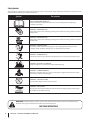
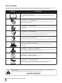
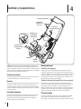
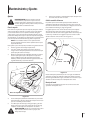
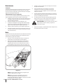
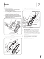
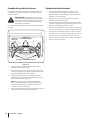
Safe Operation Practices • Set-Up • Operation • Maintenance • Service • Troubleshooting • Warranty
Operator’s Manual
— Squall 2100 Shown —
Single-Stage Snow Thrower
Squall 210 & Squall 2100
WARNING
READ AND FOLLOW ALL SAFETY RULES AND INSTRUCTIONS IN THIS MANUAL
BEFORE ATTEMPTING TO OPERATE THIS MACHINE.
FAILURE TO COMPLY WITH THESE INSTRUCTIONS MAY RESULT IN PERSONAL INJURY.
TROY-BILT LLC, P.O. BOX 361131 CLEVELAND, OHIO 44136-0019
Printed In USA
Form No. 769-08234
(May 24, 2012)
1
To The Owner
Thank You
Thank you for purchasing a Troy-Bilt Snow Thrower. It was
carefully engineered to provide excellent performance when
properly operated and maintained.
If applicable, the power testing information used to establish
the power rating of the engine equipped on this machine can be
found at www.opei.org or the engine manufacturer’s web site.
Please read this entire manual prior to operating the equipment.
It instructs you how to safely and easily set up, operate and
maintain your machine. Please be sure that you, and any other
persons who will operate the machine, carefully follow the
recommended safety practices at all times. Failure to do so could
result in personal injury or property damage.
If you have any problems or questions concerning the machine,
phone a authorized Troy-Bilt service dealer or contact us directly.
Troy-Bilt’s Customer Support telephone numbers, website
address and mailing address can be found on this page. We want
to ensure your complete satisfaction at all times.
All information in this manual is relative to the most recent
product information available at the time of printing. Review
this manual frequently to familiarize yourself with the machine,
its features and operation. Please be aware that this Operator’s
Manual may cover a range of product specifications for various
models. Characteristics and features discussed and/or illustrated
in this manual may not be applicable to all models. We reserve
the right to change product specifications, designs and
equipment without notice and without incurring obligation.
Throughout this manual, all references to right and left side of the
machine are observed from the operating position
Table of Contents
Safe Operation Practices......................................... 3
Assembly & Set-Up................................................... 7
Controls & Features................................................10
Operation.................................................................12
Maintenance & Adjustment..................................13
Service......................................................................15
Troubleshooting......................................................17
Replacement Parts..................................................18
Warranties.............................................................. 20
Record Product Information
Model Number
Before setting up and operating your new equipment, please
locate the model plate on the equipment and record the
information in the provided area to the right. You can locate the
model plate by standing at the operator’s position and looking
down at the right rear of the snow thrower. This information will
be necessary, should you seek technical support via our web site,
Customer Support Department, or with a local authorized service
dealer.
Serial Number
Customer Support
Please do NOT return the machine to the retailer or dealer without first contacting the Customer Support Department.
If you have difficulty assembling this product or have any questions regarding the controls, operation, or maintenance of
this machine, you can seek help from the experts. Choose from the options below:
◊
Visit us on the web at www.troybilt.com
See How-to Maintenance and Parts Installation Videos at www.troybilt.com/tutorials
2
◊
Call a Customer Support Representative at (800) 828-5500 or (330) 558-7220
◊
Write to Troy-Bilt LLC • P.O. Box 361131 • Cleveland, OH • 44136-0019
Important Safe Operation Practices
2
WARNING! This symbol points out important safety instructions which, if not followed,
could endanger the personal safety and/or property of yourself and others. Read and follow
all instructions in this manual before attempting to operate this machine. Failure to comply
with these instructions may result in personal injury.
When you see this symbol. HEED ITS WARNING!
CALIFORNIA PROPOSITION 65
WARNING! Engine Exhaust, some of its constituents, and certain vehicle components
contain or emit chemicals known to State of California to cause cancer and birth defects
or other reproductive harm.
DANGER: This machine was built to be operated according to the safe operation practices in
this manual. As with any type of power equipment, carelessness or error on the part of the
operator can result in serious injury. This machine is capable of amputating fingers, hands,
toes and feet and throwing foreign objects. Failure to observe the following safety
instructions could result in serious injury or death.
Training
Preparation
1.
Read, understand, and follow all instructions on the
machine and in the manual(s) before attempting to
assemble and operate. Keep this manual in a safe place for
future and regular reference and for ordering replacement
parts.
Thoroughly inspect the area where the equipment is to be used.
Remove all doormats, newspapers, sleds, boards, wires and other
foreign objects, which could be tripped over or thrown by the
auger/impeller.
2.
Be familiar with all controls and their proper operation.
Know how to stop the machine and disengage them
quickly.
3.
1.
Always wear safety glasses or eye shields during operation
and while performing an adjustment or repair to protect
your eyes. Thrown objects which ricochet can cause serious
injury to the eyes.
Never allow children under 14 years of age to operate this
machine. Children 14 and over should read and understand
the instructions and safe operation practices in this manual
and on the machine and be trained and supervised by an
adult.
2.
Do not operate without wearing adequate winter outer
garments. Do not wear jewelry, long scarves or other loose
clothing, which could become entangled in moving parts.
Wear footwear which will improve footing on slippery
surfaces.
4.
Never allow adults to operate this machine without proper
instruction.
3.
Use a grounded three-wire extension cord and receptacle
for all machines with electric start engines.
5.
Thrown objects can cause serious personal injury. Plan
your snow-throwing pattern to avoid discharge of material
toward roads, bystanders and the like.
4.
Disengage all control levers before starting the engine.
5.
Never attempt to make any adjustments while engine is
running, except where specifically recommended in the
operator’s manual.
6.
Let engine and machine adjust to outdoor temperature
before starting to clear snow.
6.
7.
Keep bystanders, pets and children at least 75 feet from the
machine while it is in operation. Stop machine if anyone
enters the area.
Exercise caution to avoid slipping or falling, especially
when operating in reverse.
3
Safe Handling of Gasoline
5.
To avoid personal injury or property damage use extreme care
in handling gasoline. Gasoline is extremely flammable and the
vapors are explosive. Serious personal injury can occur when
gasoline is spilled on yourself or your clothes which can ignite.
Wash your skin and change clothes immediately.
Never run an engine indoors or in a poorly ventilated area.
Engine exhaust contains carbon monoxide, an odorless
and deadly gas.
6.
Do not operate machine while under the influence of
alcohol or drugs.
7.
Muffler and engine become hot and can cause a burn. Do
not touch. Keep children away.
a.
Use only an approved gasoline container.
b.
Extinguish all cigarettes, cigars, pipes and other
sources of ignition.
8.
Exercise extreme caution when operating on or crossing
gravel surfaces. Stay alert for hidden hazards or traffic.
c.
Never fuel machine indoors.
9.
d.
Never remove gas cap or add fuel while the engine is
hot or running.
Exercise caution when changing direction and while
operating on slopes. Do not operate on steep slopes.
10.
e.
Allow engine to cool at least two minutes before
refueling.
Plan your snow-throwing pattern to avoid discharge
towards windows, walls, cars etc. Thus, avoiding possible
property damage or personal injury caused by a ricochet.
f.
Never over fill fuel tank. Fill tank to no more than ½
inch below bottom of filler neck to provide space for
fuel expansion.
11.
Never direct discharge at children, bystanders and pets or
allow anyone in front of the machine.
12.
Do not overload machine capacity by attempting to clear
snow at too fast of a rate.
13.
Never operate this machine without good visibility or light.
Always be sure of your footing and keep a firm hold on the
handles. Walk, never run.
14.
Disengage power to the auger/impeller when transporting
or not in use.
15.
Never operate machine at high transport speeds on
slippery surfaces. Look down and behind and use care
when backing up.
g.
Replace gasoline cap and tighten securely.
h.
If gasoline is spilled, wipe it off the engine and
equipment. Move machine to another area. Wait 5
minutes before starting the engine.
i.
Never store the machine or fuel container inside
where there is an open flame, spark or pilot light
(e.g. furnace, water heater, space heater, clothes
dryer etc.).
j.
Allow machine to cool at least 5 minutes before
storing.
16.
k.
Never fill containers inside a vehicle or on a truck
or trailer bed with a plastic liner. Always place
containers on the ground away from your vehicle
before filling.
If the machine should start to vibrate abnormally, stop
the engine, disconnect the spark plug wire and ground it
against the engine. Inspect thoroughly for damage. Repair
any damage before starting and operating.
17.
If possible, remove gas-powered equipment from
the truck or trailer and refuel it on the ground. If this
is not possible, then refuel such equipment on a
trailer with a portable container, rather than from a
gasoline dispenser nozzle.
Disengage all control levers and stop engine before you
leave the operating position (behind the handles). Wait
until the auger/impeller comes to a complete stop before
unclogging the chute assembly, making any adjustments,
or inspections.
18.
Never put your hand in the discharge or collector openings.
Do not unclog chute assembly while engine is running.
Shut off engine and remain behind handles until all moving
parts have stopped before unclogging.
19.
Use only attachments and accessories approved by the
manufacturer (e.g. wheel weights, tire chains, cabs etc.).
20.
When starting engine, pull cord slowly until resistance
is felt, then pull rapidly. Rapid retraction of starter cord
(kickback) will pull hand and arm toward engine faster than
you can let go. Broken bones, fractures, bruises or sprains
could result.
21.
If situations occur which are not covered in this manual, use
care and good judgment. Contact Customer Support for
assistance and the name of your nearest servicing dealer.
l.
m. Keep the nozzle in contact with the rim of the fuel
tank or container opening at all times until fueling is
complete. Do not use a nozzle lock-open device.
Operation
4
1.
Do not put hands or feet near rotating parts, in the auger/
impeller housing or chute assembly. Contact with the
rotating parts can amputate hands and feet.
2.
The auger/impeller control lever is a safety device. Never
bypass its operation. Doing so makes the machine unsafe
and may cause personal injury.
3.
The control levers must operate easily in both directions
and automatically return to the disengaged position when
released.
4.
Never operate with a missing or damaged chute assembly.
Keep all safety devices in place and working.
Section 2 — Important Safe Operation Practices
Clearing a Clogged Discharge Chute
Hand contact with the rotating impeller inside the discharge
chute is the most common cause of injury associated with snow
throwers. Never use your hand to clean out the discharge chute.
To clear the chute:
1.
SHUT THE ENGINE OFF!
2.
Wait 10 seconds to be sure the impeller blades have
stopped rotating.
3.
Always use a clean-out tool, not your hands.
Maintenance & Storage
1.
Never tamper with safety devices. Check their proper
operation regularly. Refer to the maintenance and
adjustment sections of this manual.
2.
Before cleaning, repairing, or inspecting machine
disengage all control levers and stop the engine. Wait until
the auger/impeller come to a complete stop. Disconnect
the spark plug wire and ground against the engine to
prevent unintended starting.
3.
Check bolts and screws for proper tightness at frequent
intervals to keep the machine in safe working condition.
Also, visually inspect machine for any damage.
4.
Do not change the engine governor setting or over-speed
the engine. The governor controls the maximum safe
operating speed of the engine.
5.
Snow thrower shave plates and skid shoes are subject to
wear and damage. For your safety protection, frequently
check all components and replace with original equipment
manufacturer’s (OEM) parts only. “Use of parts which do
not meet the original equipment specifications may lead to
improper performance and compromise safety!”
6.
Check control levers periodically to verify they engage
and disengage properly and adjust, if necessary. Refer
to the adjustment section in this operator’s manual for
instructions.
7.
Maintain or replace safety and instruction labels, as
necessary.
8.
Observe proper disposal laws and regulations for gas, oil,
etc. to protect the environment.
9.
Prior to storing, run machine a few minutes to clear snow
from machine and prevent freeze up of auger/impeller.
10.
Never store the machine or fuel container inside where
there is an open flame, spark or pilot light such as a water
heater, furnace, clothes dryer etc.
11.
Always refer to the operator’s manual for proper
instructions on off-season storage.
12.
Check fuel line, tank, cap, and fittings frequently for cracks
or leaks. Replace if necessary.
13.
Do not crank engine with spark plug removed.
14.
According to the Consumer Products Safety Commission
(CPSC) and the U.S. Environmental Protection Agency (EPA),
this product has an Average Useful Life of seven (7) years,
or 60 hours of operation. At the end of the Average Useful
Life have the machine inspected annually by an authorized
service dealer to ensure that all mechanical and safety
systems are working properly and not worn excessively.
Failure to do so can result in accidents, injuries or death.
Do not modify engine
To avoid serious injury or death, do not modify engine in any
way. Tampering with the governor setting can lead to a runaway
engine and cause it to operate at unsafe speeds. Never tamper
with factory setting of engine governor.
Notice Regarding Emissions
Engines which are certified to comply with California and federal
EPA emission regulations for SORE (Small Off Road Equipment)
are certified to operate on regular unleaded gasoline, and
may include the following emission control systems: Engine
Modification (EM), Oxidizing Catalyst (OC), Secondary Air
Injection (SAI) and Three Way Catalyst (TWC) if so equipped.
Spark Arrestor
WARNING! This machine is equipped with an
internal combustion engine and should not be used
on or near any unimproved forest-covered, brush
covered or grass-covered land unless the engine’s
exhaust system is equipped with a spark arrestor
meeting applicable local or state laws (if any).
If a spark arrestor is used, it should be maintained in effective
working order by the operator. In the State of California the
above is required by law (Section 4442 of the California Public
Resources Code). Other states may have similar laws. Federal laws
apply on federal lands.
A spark arrestor for the muffler is available through your
nearest engine authorized service dealer or contact the service
department, P.O. Box 361131 Cleveland, Ohio 44136-0019.
Section 2 — Important Safe Operation Practices
5
Safety Symbols
This page depicts and describes safety symbols that may appear on this product. Read, understand, and follow all instructions on the
machine before attempting to assemble and operate.
Symbol
Description
READ THE OPERATOR’S MANUAL(S)
Read, understand, and follow all instructions in the manual(s) before attempting to
assemble and operate
WARNING— ROTATING BLADES
Keep hands out of inlet and discharge openings while machine is running. There are rotating
blades inside
WARNING— ROTATING BLADES
Keep hands out of inlet and discharge openings while machine is running. There are rotating
blades inside
WARNING— ROTATING AUGER
Do not put hands or feet near rotating parts, in the auger/impeller housing or chute
assembly. Contact with the rotating parts can amputate hands and feet.
WARNING—THROWN OBJECTS
This machine may pick up and throw and objects which can cause serious personal injury.
WARNING—GASOLINE IS FLAMMABLE
Allow the engine to cool at least two minutes before refueling.
WARNING— CARBON MONOXIDE
Never run an engine indoors or in a poorly ventilated area. Engine exhaust contains carbon
monoxide, an odorless and deadly gas.
WARNING— ELECTRICAL SHOCK
Do not use the engine’s electric starter in the rain
WARNING— HOT SURFACE
Engine parts, especially the muffler, become extremely hot during operation. Allow engine
and muffler to cool before touching.
WARNING! Your Responsibility—Restrict the use of this power machine to persons who read, understand and
follow the warnings and instructions in this manual and on the machine.
SAVE THESE INSTRUCTIONS!
6
Section 2 — Important Safe Operation Practices
3
Assembly & Set-Up
Contents of Carton
•
One Snow Thrower
•
One 20 oz. Bottle 5W-30 Oil
•
Two Ignition Keys
•
One Chute Assembly
•
One Chute Rotation Control (If equip.)
•
One Set of Drift Cutters (If equip.)
•
One Electric Starter Cord (If equip.)
•
One Snow Thrower Operator’s Manual •
NOTE: This Operator’s Manual covers several models. Snow
thrower features may vary by model. Not all features in this
manual are applicable to all snow thrower models and the snow
thrower depicted may differ from yours.
2.
One Engine Operator’s Manual
Pivot the upper handle into the operating position. Be sure
not to pinch any of the cables in the process. See Figure 3-2.
NOTE: All references to the left or right side of the snow thrower
are from the operator’s position. Any exceptions will be noted.
Tools Required
•
• One 5/16-inch wrench (or adjustable wrench)
•
• One 1/2-inch wrench (or adjustable wrench)
Assembly
Positioning the Upper Handle
1.
Remove the wing knob and carriage bolt from the top
of the lower handle. See Figure 3-1. It is not necessary to
remove the shoulder screw and flange lock nut below the
wing knob and carriage bolt.
Wing Knob
Figure 3-2
Installing the Chute
Carriage Bolts
1.
Wing Knob
Remove the hex washer screws in the chute base. See
Figure 3-3.
Figure 3-1
Figure 3-3
7
2.
Align the holes in the chute base with the holes in the
lower chute and secure with the previously removed hex
washer screws. See Figure 3-4.
Installing the Drift Cutters (If so equipped)
1.
Remove the carriage bolts and flange lock nuts from the
drift cutters.
2.
Install the drift cutters and secure with the carriage bolts
and flange lock nuts removed in step 1. See Figure 3-6.
Drift Cutter
Flange Lock Nut
Carriage Bolt
Figure 3-4
Installing the Chute Rotation Control (If so equipped)
To install the chute rotation control (only models so equipped)
proceed as follows:
1.
Remove the hex lock nut and machine screw from the
chute rotation control. See Figure 3-5.
Figure 3-6
Installing the Recoil Starter Handle
1.
Remove the eye bolt and handle knob from the manual
bag.
2.
Place the eye bolt and handle knob on the upper handle as
shown in Figure 3-7. Do not fully tighten the hardware until
instructed to do so.
1
Chute Rotation Control
Hex Lock
Nut
Machine Screw
Eye Bolt
Recoil Starter
Handle
2
Hex Lock
Nut
Chute Control Rod
Machine Screw
Figure 3-5
2.
Place the chute rotation control onto the chute rotation
rod and secure with the hex lock nut and machine screw
removed in step 1. See Figure 3-5.
A
Handle
Knob
B
Figure 3-7
NOTE: The opening of the eye bolt should face toward the
back of the snow thrower.
8
Section 3— Assembly & Set-Up
3.
Slowly pull the recoil starter handle up towards the eye
bolt.
4.
Slip the recoil starter rope into the eye bolt from the back
of the snow thrower. See Figure 3-7.
5.
Securely tighten the eye bolt and handle knob.
Set-Up
Adding Oil
Refer to the Engine Operator’s Manual packed with your snow
thrower for information on adding and checking oil.
Adding Fuel
Refer to the Engine Operator’s Manual packed with your snow
thrower for information on adding fuel.
Section 3 — Assembly & Set-Up
9
4
Controls & Features
Auger Control
Recoil Starter Handle
Chute Rotation
Control
EZ Chute
Low-Crank
Chute Assembly
Drift Cutters
Auger
Shave Plate
NOTE: This Operator’s Manual covers several models. Snow
thrower features may vary by model. Not all features in this
manual are applicable to all snow thrower models and the snow
thrower depicted may differ from yours.
Engine Controls
See the Engine Operator’s Manual for the location and function
of the controls on the engine.
Auger
When engaged, the auger rotation draws snow into the auger
housing and throws it out the discharge chute. Rubber paddles
on the auger also aid in propelling the snow thrower as they
come in contact with the pavement.
Auger Control
Located on the upper handle, the auger control is used to
engage and disengage drive to the auger. Squeeze the control
against the upper handle to engage the auger; release it to
disengage.
10
Chute Assembly
EZ Chute (If so equipped)
Rotate the discharge chute to the left or right using the chute
handle. The pitch of the discharge chute controls the angle at
which the snow is thrown. Loosen the wing knob on the side of
the discharge chute before pivoting the discharge chute upward
or downward. Retighten the knob once the desired position has
been achieved.
Low-Crank Chute Assembly (If so equipped)
Rotate the discharge chute to the left or right using the chute
rotation control. The pitch of the discharge chute controls the
angle at which the snow is thrown. Loosen the wing knob on the
side of the discharge chute before pivoting the discharge chute
upward or downward. Retighten the knob once the desired
position has been achieved.
Shave Plate
The shave plate maintains contact with the pavement as
the snow thrower is propelled, allowing snow close to the
pavement’s surface to be discharged.
Recoil Starter Handle
The recoil starter handle is used to manually start the engine.
Chute Rotation Control (If so equipped)
The chute rotation control is located on the back of the snow
thrower. To rotate the chute to the left, squeeze the lever against
the chute rotation control and rotate left. To rotate the chute to
the right, squeeze the lever against the chute rotation control
and rotate right.
Drift Cutters (If so Equipped)
The drift cutters are designed for use in deep snow. Their use
is optional for normal snow conditions. Maneuver the snow
thrower so that the cutters penetrate a high standing snow drift
to assist snow falling into the augers for throwing.
Section 4 — Controls & Features
11
5
Operation
Starting & Stopping the Engine
WARNING! Always keep hands and feet clear of
Low-Crank Chute Assembly (If so equipped)
1.
moving parts. Do not use a pressurized starting
fluid. Vapors are flammable.
Rotate the discharge chute to the left or right using the
chute rotation control. See Figure 5-2.
Chute Control Handle
Refer to the Engine Operator’s manual packed with your snow
thrower for instructions on starting and stopping the engine.
Engaging the Auger
Discharge Chute
To engage the auger and start throwing snow, squeeze the auger
control against the handle. Release to stop the auger.
Engaging the Drive
Lift up slightly on the handle to allow the rubber paddles on the
auger to contact the pavement and propel the snow thrower
forward. Pushing downward on the handle will raise the auger
off the ground and stop the forward motion.
Wing Knob
NOTE: Excessive upward pressure on the handle will result
in premature wear on the rubber auger blades which are
not be covered by the warranty.
Adjusting the Chute
Figure 5-2
EZ Chute (If so equipped)
1.
2.
Rotate the discharge chute to the left or right using the
chute handle. See Figure 5-1.
Chute Handle
To adjust the pitch, loosen the wing knob on the side of the
discharge chute and pivot the discharge chute upward or
downward. Retighten the knob once the desired position
has been achieved. See Figure 5-2.
Clearing a Clogged Discharge Chute
Discharge Chute
WARNING! Never use your hands to clear a
clogged chute assembly. Shut off engine and remain
behind handles until all moving parts have stopped
before using a clean-out tool to clear the chute
assembly.
Hand contact with the rotating impeller inside the discharge
chute is the most common cause of injury associated with snow
throwers. Never use your hand to clean out the discharge chute.
To clear the chute:
Wing Knob
Figure 5-1
2.
12
To adjust the pitch, loosen the wing knob on the side of the
discharge chute and pivot the discharge chute upward or
downward. Retighten the knob once the desired position
has been achieved. See Figure 5-1.
1.
SHUT THE ENGINE OFF!
2.
Wait 10 seconds to be sure the impeller blades have
stopped rotating.
3.
Always use a clean-out tool, not your hands.
6
Maintenance & Adjustments
Adjustments
Auger Control Cable
WARNING! Before servicing, repairing or
inspecting the snow thrower, disengage the auger
control. Stop the engine and remove the key to
prevent unintended starting.
Shave Plate
To check the adjustment of the shave plate, place the machine
on a level surface. The wheels, shave plate and auger should all
contact the level surface. Note that if the shave plate is adjusted
too high, snow may blow under the housing. If the shave plate
wears out excessively, or the snow thrower does not self-propel,
the shave plate may be too low and needs to be adjusted.
As a result of both the auger control cable and the auger drive belt
stretching due to wear, periodic adjustments may be necessary. If
the auger seems to hesitate when rotating, proceed as follows:
The upper hole in the auger control provides for an adjustment
in cable tension. To adjust, disconnect the end of control cable
from the bottom hole in the auger handle and reinsert it in the
upper hole. Insert the cable from the outside as shown in Figure
6-2.
NOTE: On new snow throwers or machines with a new shave
plate installed, the auger may be slightly off the ground.
Control
Handle
To adjust the shave plate proceed as follows:
1.
Drain the gas from the snow thrower.
2.
Pull the starter cord until resistance is felt. Then tip the
snow thrower back until it rests on the handles.
3.
Loosen the four flange lock nuts and carriage screws which
secure the shave plate to the housing. See Figure 6-1. Move
the shave plate to the desired position and retighten the
flange lock nuts and carriage screws securely.
Control
Cable
Side View
Carriage
Screw
Flange
Lock Nut
Figure 6-2
Test the snow thrower to see if there is a noticeable difference.
If after the adjustment to the auger control cable the auger still
hesitates when rotating, see the Service section to replace the belt.
Chute Assembly
Refer to the Operation section for instructions on adjusting the
chute assembly.
Reversible Shave Plate
Figure 6-1
4.
Tip the snow thrower back to the operating position and pull
the starter handle a few times to see if it is difficult to pull.
5.
If the starter is difficult to pull, remove the spark plug and
pull the handle several times to ensure that any oil trapped
in the head is removed.
CAUTION: Oil may come out of the spark plug
hole when it is removed and the starter handle is
pulled.
6.
Inspect the spark plug. If it is wet, clean off any oil before
re-installing.
13
Maintenance
3.
Lubrication
Change the oil and/or the spark plug as instructed in your
Engine Operator’s manual.
4.
Re-install the lower panel by placing the tabs in the tab
slots, lifting the panel into place and secure with the three
screws removed in step 2.
5.
Tip the snow thrower back to the operating position and pull
the starter handle a few times to see if it is difficult to pull.
6.
If the starter is difficult to pull, remove the spark plug and
pull the handle several times to ensure that any oil trapped
in the head is removed.
Lubricate the pivot points on the control handle and the
extension spring at the end of the control cable with a light
oil once every season and before the snow thrower is put into
storage at the end of the season.
Off-Season Storage
If the snow thrower will not be used for 30 days or longer, follow
the instructions below.
1.
Refer to the Engine Operator’s manual packed with your
snow thrower for information on the storage of the engine.
2.
Store the equipment in a clean, dry area.
3.
If storing in an unventilated area, rustproof the machine
using a light oil or silicone to coat the snow thrower.
4.
Clean the exterior of the engine and the snow thrower.
5.
Lubricate pivot points on control handle and extension
spring at end of control cable with a light oil.
Engine
Refer to the Engine Operators manual packed separately with
your snow thrower for maintenance and adjustment information
on your engine.
1.
To access the oil drain and spark plug on model 2T5 it is
necessary to remove the lower panel.
2.
Remove the three screws that secure the lower panel.
Remove the lower panel by lifting up on the panel to free
the tabs at the bottom of the panel from the tab slots and
then pull back. See Figure 6-3.
Figure 6-3
NOTE: The bottom of the panel has tabs that help hold it in
place.
NOTE: An oil drain extension kit is available separately.
Contact your local Troy-Bilt dealer or contact Troy-Bilt’s
Customer Support for kit #753-06684.
14
Section 6— Maintenance & Adjustments
CAUTION: Oil may come out of the spark plug hole
when it is removed and the starter handle is pulled.
7.
Inspect the spark plug. If it is wet, clean off any oil before
re-installing.
7
Service
Replacing Belt
To replace the belt follow these instructions and refer to Figure 7-3:
1.
Run the snow thrower until the fuel tank is empty.
2.
Pull the recoil starter handle until resistance is felt. Then tip
the snow thrower back until it rests on the handles.
3.
Slide a board up through the auger and through the chute
to secure the auger in place.
4.
Remove the belt cover by removing the two hex washer
screws and one hex lock screw that secure it to the frame.
See Figure 7-1.
Drive Pulley
Idler Pulley
Belt
Keeper
Hex Lock Screw
Flange Nut
Auger
Pulley
Figure 7-3
1.
Route the belt around the drive pulley and under the idler
pulley.
2.
Route the end of the belt around the auger pulley and slide
the pulley back on to the auger shaft. It may be necessary
to push down on the idler pulley to get the auger pulley
under the belt keeper.
3.
Replace the flange nut and tighten securely.
4.
Reinstall the belt cover removed earlier.
5.
Remove the board from the auger and chute.
Hex Washer Screw
Figure 7-1
5.
Remove the flange nut that secures the auger pulley to the
auger shaft. See Figure 7-2.
Flange Nut
Auger Shaft
Auger Pulley
Figure 7-2
6.
Remove the auger pulley and the belt.
15
Replacing Auger Paddles
Replacing Shave Plate
The snow thrower auger’s rubber paddles are subject to wear
and should be replaced if any signs of excessive wear are present.
1.
The shave plate is attached to the bottom of the auger
housing and is subject to wear. It should be checked
periodically. There are two wearing edges and the shave
plate can be reversed.
2.
Run the snow thrower until the fuel tank is empty.
3.
Pull the recoil starter handle until resistance is felt. Then tip
the snow thrower back until it rests on the handles.
4.
Remove the four carriage bolts and flange lock nuts which
attach it to the snow thrower housing.
5.
Reverse the existing shave plate or install a new one,
making sure the new shave plate and the heads of the
carriage bolts are on the inside of the housing.
6.
Adjust the shave plate as instructed on page 11.
7.
Tighten securely once adjusted.
CAUTION: Do NOT allow the auger’s rubber
paddles to wear to the point where portions of the
metal auger itself can come in contact with the
pavement. Doing so can result in serious damage to
your snow thrower.
To change the rubber paddles, proceed as follows and refer to
Figure 7-4:
Auger Paddle
Hex Washer Screw
Hex Washer Screw
Figure 7-4
1.
Run the snow thrower until the fuel tank is empty.
2.
Pull the recoil starter handle until resistance is felt. Then tip
the snow thrower back until it rests on the handles.
3.
Remove the existing rubber paddles by unthreading the
hex washer screws which secure them to the auger. See
Figure 7-4.
NOTE: The auger paddles should be replaced one at a time
so that the auger still attached can be used as an example
for positioning and re-installing the new auger.
4.
16
Secure the replacement rubber paddles to the auger using
the hardware removed earlier.
Section 7— Service
8
Troubleshooting
Problem
Cause
Remedy
Excessive vibration
1. Loose parts or damaged auger.
1. Stop engine immediately and disconnect
spark plug wire. Check for possible damage.
Tighten all bolts and nuts. Repair as needed.
If the problem persists, take snow thrower to
an authorized service dealer.
Snow thrower fails to selfpropel
1. Auger control cable out of adjustment.
1. Adjust auger control cable as shown in
Maintenance & Adjustments section.
2. Auger drive belt loose or damaged.
2. Replace auger drive belt.
Augers continue to rotate
1. Auger control cable out of adjustment.
1. Adjust auger control cable as shown in
Maintenance & Adjustments section.
Snow thrower fails to
discharge snow
1. Chute assembly clogged.
1. Stop engine and disconnect spark plug wire.
Clean chute and inside of auger housing with
clean-out tool or stick.
2. Foreign object lodged in auger.
2. Stop engine immediately and disconnect the
spark plug wire. Remove object from auger.
3. Auger control cable out of adjustment.
3. Adjust auger control cable.
4. Auger belt loose or damaged.
4. Replace auger belt.
17
9
Replacement Parts
Component
Part Number and Description
731-08171
Shave Plate
954-04050
Belt V-Type
753-06469
Rubber Auger Paddle Kit (Includes 2
paddles and 12 hex washer screws)
731-05632
Key
946-04782
946-04701
Clutch Cable (Squall 210)
Clutch Cable (Squall 2100)
634-04607
734-04033
Wheel Assembly, 7 x 2 (Squall 210)
Wheel Assembly, 8 x 2.125 (Squall 2100)
Phone (800) 800-7310 to order replacement parts or a complete Parts Manual (have your full model number and serial number ready).
Parts Manual downloads are also available free of charge at www.mtdproducts.com.
18
Notes
10
19
MANUFACTURER’S LIMITED WARRANTY FOR
The limited warranty set forth below is given by Troy-Bilt LLC with
respect to new merchandise purchased and used in the United States
and/or its territories and possessions, and by MTD Products Limited
with respect to new merchandise purchased and used in Canada and/
or its territories and possessions (either entity respectively, “TroyBilt”).
b. Routine maintenance items such as lubricants, filters, blade
sharpening, tune-ups, brake adjustments, clutch adjustments,
deck adjustments, and normal deterioration of the exterior finish
due to use or exposure.
This warranty is in addition to any applicable emissions warranty
provided with your product.
d. Troy-Bilt does not extend any warranty for products sold or
exported outside of the United States and/or Canada, and their
respective possessions and territories, except those sold through
Troy-Bilt’s authorized channels of export distribution.
“Troy-Bilt” warrants this product (excluding its Normal Wear Parts
and Attachments as described below) against defects in material and
workmanship for a period of two (2) years commencing on the date
of original purchase and will, at its option, repair or replace, free of
charge, any part found to be defective in materials or workmanship.
This limited warranty shall only apply if this product has been
operated and maintained in accordance with the Operator’s Manual
furnished with the product, and has not been subject to misuse,
abuse, commercial use, neglect, accident, improper maintenance,
alteration, vandalism, theft, fire, water, or damage because of other
peril or natural disaster. Damage resulting from the installation or use
of any part, accessory or attachment not approved by Troy-Bilt for use
with the product(s) covered by this manual will void your warranty as
to any resulting damage.
Normal Wear Parts are warranted to be free from defects in material
and workmanship for a period of thirty (30) days from the date of
purchase. Normal wear parts include, but are not limited to items
such as: batteries, belts, blades, blade adapters, tines, grass bags,
wheels, rider deck wheels, seats, snow thrower skid shoes, friction
wheels, shave plates, auger spiral rubber and tires.
Attachments — Troy-Bilt warrants attachments for this product
against defects in material and workmanship for a period of one (1)
year, commencing on the date of the attachment’s original purchase
or lease. Attachments include, but are not limited to items such as:
grass collectors and mulch kits.
HOW TO OBTAIN SERVICE: Warranty service is available, WITH
PROOF OF PURCHASE, through your local authorized service dealer.
To locate the dealer in your area:
In the U.S.A.
Check your Yellow Pages, or contact Troy-Bilt LLC at P.O. Box 361131,
Cleveland, Ohio 44136-0019, or call 1-866-840-6483,
1-330-558-7220 or log on to our Web site at www.troybilt.com.
In Canada
Contact MTD Products Limited, Kitchener, ON N2G 4J1, or call 1-800668-1238 or log on to our Web site at www.mtdcanada.com.
This limited warranty does not provide coverage in the following
cases:
a. Log splitter pumps, valves, and cylinders have a separate oneyear warranty.
c. Service completed by someone other than an authorized service
dealer.
e. Replacement parts that are not genuine Troy-Bilt parts.
f. Transportation charges and service calls.
g. Troy-Bilt does not warrant this product for commercial use.
No implied warranty, including any implied warranty of
merchantability or fitness for a particular purpose, applies after
the applicable period of express written warranty above as to the
parts as identified. No other express warranty, whether written or
oral, except as mentioned above, given by any person or entity,
including a dealer or retailer, with respect to any product, shall
bind Troy-Bilt. During the period of the warranty, the exclusive
remedy is repair or replacement of the product as set forth above.
The provisions as set forth in this warranty provide the sole and
exclusive remedy arising from the sale. Troy-Bilt shall not be liable
for incidental or consequential loss or damage including, without
limitation, expenses incurred for substitute or replacement lawn
care services or for rental expenses to temporarily replace a
warranted product.
Some states do not allow the exclusion or limitation of incidental
or consequential damages, or limitations on how long an implied
warranty lasts, so the above exclusions or limitations may not apply
to you.
In no event shall recovery of any kind be greater than the amount of
the purchase price of the product sold. Alteration of safety features of
the product shall void this warranty. You assume the risk and liability
for loss, damage, or injury to you and your property and/or to others
and their property arising out of the misuse or inability to use the
product.
This limited warranty shall not extend to anyone other than the
original purchaser or to the person for whom it was purchased as a
gift.
HOW STATE LAW RELATES TO THIS WARRANTY: This limited
warranty gives you specific legal rights, and you may also have other
rights which vary from state to state.
IMPORTANT: Owner must present Original Proof of Purchase to
obtain warranty coverage.
Troy-Bilt LLC, P.O. BOX 361131 CLEVELAND, OHIO 44136-0019; Phone: 1-866-840-6483, 1-330-558-7220
MTD Canada Limited - KITCHENER, ON N2G 4J1; Phone 1-800-668-1238
GDOC-100166 REV. A
Medidas importantes de seguridad • Configuración • Funcionamiento • Mantenimiento • Servicio • Solución de problemas • Garantía
Manual del Operador
— Squall 2100 Que Aparecen —
Máquina quitanieve de etapa única
Squall 210 & Squall 2100
ADVERTENCIA
LEA Y RESPETE TODAS LAS NORMAS DE SEGURIDAD E INSTRUCCIONES INCLUIDAS EN ESTE
MANUAL ANTES DE PONER EN FUNCIONAMIENTO ESTA MÁQUINA.
SI NO RESPETA ESTAS INSTRUCCIONES PUEDE PROVOCAR LESIONES PERSONALES.
TROY-BILT LLC, APARTADO POSTAL 361131 CLEVELAND, OHIO 44136-0019
Impreso en Estados Unidos de América
Formulario No. 769-08234
(Mayo 24, 2012)
1
Al propietario
Gracias
Gracias por comprar una MTD máquina quitanieve. La misma
ha sido diseñada cuidadosamente para brindar excelente
rendimiento si se la opera y mantiene correctamente.
Por favor lea todo este manual antes de operar el equipo.
Le indica cómo configurar, operar y mantener la máquina
con seguridad y fácilmente. Por favor asegúrese de seguir
cuidadosamente y en todo momento las prácticas de seguridad
recomendadas, y hacérselas seguir a cualquier otra persona que
opere la máquina. En caso de no hacerlo podrían producirse
lesiones personales o daños materiales.
Toda la información contenida en este manual hace referencia
a la más reciente información de producto disponible en el
momento de la impresión. Revise el manual frecuentemente
para familiarizarse con la unidad, sus características y
funcionamiento. Por favor tenga en cuenta que este Manual
del Operador puede cubrir una gama de especificaciones de
productos de diferentes modelos. Las características y funciones
incluidas y/o ilustradas en este manual pueden no ser aplicables
a todos los modelos. MTD se reserva el derecho de modificar
las especificaciones de los productos, los diseños y el equipo
estándar sin previo aviso y sin generar responsabilidad por
obligaciones de ningún tipo.
En su caso, los datos de prueba de potencia utilizados para
establecer la máxima potencia equipado en esta máquina se
pueden encontrar en www.opei.org o sitio web del fabricante
del motor. Si tiene algún problema o duda respecto a la unidad,
llame a un distribuidor de servicio MTD autorizado o póngase en
contacto directamente con nosotros. Los números de teléfono,
dirección del sitio web y dirección postal de la Asistencia al
Cliente de MTD se encuentran en esta página. Queremos
garantizar su entera satisfacción en todo momento.
En este manual, las referencias al lado derecho o izquierdo de la
máquina se observan desde la posición del operador.
El fabricante del motor es el responsable de todas las
cuestiones relacionadas con el rendimiento, potencia de salida,
especificaciones, garantía y mantenimiento del motor. Para
obtener mayor información consulte el Manual del Propietario /
Operador entregado por el fabricante del motor, que se envía, en
un paquete por separado, junto con su unidad.
Índice
Medidas importantes de seguridad....................... 3 Mantenimiento y Ajustes........................................13
Montaje y Configuración......................................... 7 Servicio.....................................................................15
Controles y características.....................................10 Solución de problemas...........................................17
Funcionamiento......................................................12 Garantías................................................................ 20
Registro de información de producto
Número de Modelo
Antes de configurar y operar su equipo nuevo, por favor localice
la placa de modelo en el equipo y registre la información en el
área situada a la derecha. Para encontrar la placa de modelo,
colóquese en la posición del operador y mire hacia abajo en
la parte posterior derecha de la cubierta. Si tiene que solicitar
soporte técnico a través de nuestro sitio web, el Departamento
de Asistencia al Cliente, o de un distribuidor de servicio
autorizado local, necesitará esta información.
Número de Serie
Asistencia al Cliente
Por favor, NO devuelva la unidad al minorista o distribuidor sin ponerse en contacto primero con el Departamento de
Asistencia al Cliente.
En caso de tener problemas para montar este producto o de tener dudas con respecto a los controles, funcionamiento o
mantenimiento del mismo, puede solicitar la ayuda de expertos. Elija entre las opciones que se presentan a continuación:
◊
Visite nuestro sitio web en www.mtdproducts.com
Ver Vídeos demostrativos de instalación de mantenimiento y piezas en www.mtdparts.com/KnowledgeCenter
2
◊
Llame a un representante de Asistencia al Cliente al (800) 800-7310 ó (330) 220-4683
◊
Escríbanos a MTD LLC • P.O. Box 361131 • Cleveland, OH • 44136-0019
2
Medidas importantes de seguridad
¡ADVERTENCIA! La presencia de este símbolo indica que se trata de instrucciones
importantes de seguridad que se deben respetar para evitar poner en peligro su seguridad
personal y/o material y la de otras personas. Lea y siga todas las instrucciones de este manual
antes de poner en funcionamiento esta máquina. Si no respeta estas instrucciones puede
provocar lesiones personales.
Cuando vea este símbolo. ¡TENGA EN CUENTAS LAS ADVERTENCIAS!
PROPOSICIÓN 65 DE CALIFORNIA
¡ADVERTENCIA! El escape del motor de este producto, algunos de sus componentes y
algunos componentes del vehículo contienen o liberan sustancias químicas que el estado
de California considera que pueden producir cáncer, defectos de nacimiento u otros
problemas reproductivos.
PELIGRO: Esta máquina está diseñada para ser utilizada respetando las normas de
seguridad contenidas en este manual. Al igual que con cualquier tipo de equipo motorizado,
un descuido o error por parte del operador puede producir lesiones graves. Esta máquina es
capaz de amputar dedos, manos y pies y de arrojar objetos extraños con gran fuerza. De no
respetar las instrucciones de seguridad siguientes se pueden producir lesiones graves o la
muerte.
Capacitación
Preparativos
1.
Lea, entienda y cumpla todas las instrucciones incluidas en
la máquina y en los manuales antes de montarla y utilizarla.
Guarde este manual en un lugar seguro para consultas
futuras y periódicas, así como para solicitar repuestos.
Inspeccione minuciosamente el área donde utilizará el equipo.
Saque todos los felpudos, periódicos, trineos, tablas, cables y
otros objetos extraños con los que podría tropezar o que podrían
ser arrojados por la barrena / impulsor.
2.
Familiarícese con todos los controles y con el uso adecuado
de los mismos. Sepa cómo detener la máquina y desactivar
los controles rápidamente.
1.
3.
No permita nunca que los niños menores de 14 años
utilicen esta máquina. Los niños de 14 años en adelante
deben leer y entender las instrucciones de operación y
normas de seguridad contenidas en este manual, y en la
máquina ydeben ser entrenados y supervisados por un
adulto.
Para protegerse los ojos utilice siempre anteojos o
antiparras de seguridad mientras opera la máquina o
mientras la ajusta o repara. Los objetos arrojados que
rebotan pueden producir lesiones oculares graves.
2.
No opere la máquina sin la vestimenta adecuada para
estar al aire libre en invierno. No utilice alhajas, bufandas
largas u otras prendas sueltas que podrían enredarse en las
partes móviles. Utilice un calzado especial para superficies
resbaladizas.
4.
Nunca permita que los adultos operen esta máquina sin
recibir antes la instrucción apropiada.
3.
5.
Los objetos arrojados por la máquina pueden producir
lesiones graves. Planifique el patrón en el que va a ir
arrojando nieve para evitar que la descarga de material se
realice hacia los caminos, los observadores, etc.
Use un prolongador y un tomacorriente de tres cables con
conexión a tierra para todas las máquinas con motores de
encendido eléctrico.
4.
Desengrane todas las palancas de control antes de arrancar
el motor.
6.
Mantenga a los observadores, ayudantes, mascotas y niños
por lo menos a 75 pies de la máquina mientras la misma
está en funcionamiento. Detenga la máquina si alguien se
acerca.
5.
Nunca intente realizar ajustes mientras el motor está
en marcha excepto en los casos específicamente
recomendados en el manual del operador.
6.
Deje que el motor y la máquina se adapten a la
temperatura exterior antes de comenzar a sacar la nieve.
7.
Sea precavido para evitar patinarse o caerse especialmente
cuando opera la máquina en reversa.
3
Manejo seguro de la gasolina
Para evitar lesiones personales o daños materiales tenga mucho
cuidado cuando trabaje con gasolina. La gasolina es sumamente
inflamable y sus vapores pueden causar explosiones. Si se
derrama gasolina encima o sobre la ropa se puede lesionar
gravemente ya que se puede incendiar. Lávese la piel y cámbiese
de ropa de inmediato.
a.
b.
Utilice sólo los recipientes para gasolina autorizados.
Apague todos los cigarrillos, cigarros, pipas y otras
fuentes de combustión.
c. Nunca cargue combustible en la máquina en un
espacio cerrado.
d. Nunca saque la tapa del combustible ni agregue
combustible mientras el motor está caliente o en
marcha.
e. Deje que el motor se enfríe por lo menos dos
minutos antes de volver a cargar combustible.
f. Nunca llene en exceso el depósito de combustible.
Llene el tanque a no más de ½ pulgada por debajo
de la base del cuello de llenado dejando espacio
para la dilatación del combustible.
g. Vuelva a colocar la tapa de la gasolina y ajústela
bien.
h. Limpie el combustible que se haya derramado sobre
el motor y el equipo. Traslade la máquina a otra
zona. Espere 5 minutos antes de encender el motor.
i. Nunca almacene la máquina o el recipiente de
combustible en un espacio cerrado donde haya
fuego, chispas o luz piloto (por ejemplo, hornos,
calentadores de agua, calefactores, secadores de
ropa, etc.).
j. Deje que la máquina se enfríe por lo menos 5
minutos antes de guardarla.
k. Nunca llene los recipientes en el interior de
un vehículo o camión o caja de remolque con
recubrimientos plásticos. Coloque siempre los
recipientes en el piso y lejos del vehículo antes de
llenarlos.
l. Si es posible, retire el equipo a gasolina del camión o
remolque y llénelo en el suelo. Si esto no es posible,
llene el equipo en un remolque con contenedor
portátil, en vez de desde una boquilla dispensadora
de gasolina.
m. Mantenga la boquilla dispensadora en contacto
con el borde del depósito de combustible o con la
abertura del recipiente en todo momento, hasta
terminar la carga. No utilice un dispositivo de
apertura/cierre de boquilla.
4.
5.
6.
7.
8.
9.
10.
11.
12.
13.
14.
15.
16.
17.
18.
Funcionamiento
1.
2.
3.
4
No ponga las manos o los pies cerca de las piezas
rotatorias, en la caja de la barrena / impulsor o en el
montaje del canal de descarga. Hacer contacto con piezas
giratorias puede resultar en la amputación de manos o
pies.
La palanca de control de la barrena / impulsor es un
dispositivo de seguridad. Nunca evite su funcionamiento.
De hacerlo la operación de la máquina es riesgosa y puede
ocasionar lesiones.
Las palancas de control deben funcionar bien en ambas
direcciones y regresar automáticamente a la posición de
desengrane cuando se las suelta.
Section 2 — Medidas importantes de seguridad
19.
20.
Nunca opere la máquina si falta un montaje del canal o si
el mismo está dañado. Mantenga todos los dispositivos de
seguridad en su lugar y en funcionamiento.
Nunca encienda el motor en espacios cerrados o en una
zona con poca ventilación. El escape del motor contiene
monóxido de carbono, un gas inodoro y letal.
No utilice la máquina bajo la influencia del alcohol o las
drogas.
El silenciador y el motor se calientan y pueden causar
quemaduras. No los toque. Mantenga a los niños alejados.
Sea sumamente precavido cuando opere la máquina sobre
una superficie con grava o cuando la cruce. Manténgase
alerta por si se presentan peligros ocultos o tránsito.
Tenga cuidado cuando cambie de dirección o cuando
opere la máquina en pendientes. Tenga cuidado cuando
cambie de dirección o cuando opere la máquina en
pendientes.
Planifique el patrón en el que va a ir arrojando nieve para
evitar que la descarga de material se produzca hacia las
ventanas, las paredes, los automóviles, etc. y evitar así
posibles daños materiales o lesiones producidas por los
rebotes.
Nunca dirija la descarga hacia los niños, los observadores
o las mascotas ni deje que nadie se pare delante de la
máquina.
No sobrecargue la capacidad de la máquina tratando de
sacar la nieve muy rápidamente.
Nunca opere esta máquina sin buena visibilidad o
iluminación. Siempre debe estar seguro de que está bien
afirmado y sujetando firmemente las manijas. Camine,
nunca corra.
Corte la corriente a la barrena / impulsor cuando transporte
la máquina o cuando la misma no está en uso.
Nunca opere la máquina a alta velocidad de
desplazamiento sobre superficies resbaladizas. Mire hacia
abajo y hacia atrás y tenga cuidado cuando vaya marcha
atrás.
Si la máquina comenzara a vibrar de manera anormal,
detenga el motor, desconecte el cable de la bujía y póngala
de manera que haga masa contra el motor. Inspeccione la
máquina minuciosamente para ver si está dañada. Repare
todos los daños antes de encender y operar la máquina.
Desengrane todas las palancas de control y detenga el
motor antes de dejar la posición de operación (detrás de
las manijas). Espere a que la barrena / impulsor se detenga
por completo antes de destapar el montaje del canal o
realizar ajustes e inspecciones.
Nunca ponga las manos en las aberturas de descarga o
de recolección. Utilice siempre la herramienta de limpieza
que se adjunta para destapar la abertura de descarga. No
destape el montaje del canal mientras el motor está en
funcionamiento. Antes de destaparlo, apague el motor
y permanezca detrás de las manijas hasta que todas las
partes móviles se hayan detenido.
Use sólo uniones y accesorios aprobados por el fabricante
(por ejemplo, pesas para las ruedas, cadenas para los
neumáticos, cabinas, etc.).
Para encender el motor, jale de la cuerda lentamente hasta
que sienta resistencia, luego jale rápidamente. El repliegue
rápido de la cuerda de arranque (tensión de retroceso) le
jalará la mano y el brazo hacia el motor más rápido de lo
que usted puede soltar. El resultado pueden ser huesos
rotos, fracturas, hematomas o esguinces.
21.
Si se presentan situaciones que no están previstas en este
manual, sea cuidadoso y use el sentido común. Póngase en
contacto con Asistencia al Cliente para solicitar ayuda y el
nombre del distribuidor de servicio más cercano.
10.
Nunca almacene la máquina o el recipiente de combustible
en un espacio cerrado donde haya fuego, chispas o luz
piloto como por ejemplo, calentadores de agua, hornos,
secadores de ropa, etc.
Borrado de una Tolva de descarga obstruida
11.
Contacto directo con la rotación del impulsor en el interior de la
tolva de descarga es la causa más común de lesiones asociadas
con nieve lanzallamas. Nunca use su mano para limpiar la tolva
de descarga.
Consulte siempre el manual del operador para obtener
instrucciones adecuadas para el almacenamiento fuera de
temporada.
12.
Verifique frecuentemente la línea de combustible, el
tanque, el tapón, y los accesorios buscando rajaduras o
pérdidas. Reemplace de ser necesario.
13.
No dé arranque al motor si no está la bujía de encendido.
14.
Según la Comisión de Seguridad de Productos para el
Consumidor de los Estados Unidos (CPSC) y la Agencia
de Protección Ambiental de los Estados Unidos (EPA),
este producto tiene una vida útil media de siete (7) años,
ó 60 horas de funcionamiento. Al finalizar la vida útil
media, adquiera una máquina nueva o haga inspeccionar
anualmente ésta por un distribuidor de servicio autorizado
para cerciorarse de que todos los sistemas mecánicos y de
seguridad funcionan correctamente y no tienen excesivo
desgaste. Si no lo hace, pueden producirse accidentes,
lesiones o muerte
Para vaciar la tolva:
1.
APAGAR EL MOTOR APAGADO!
2.
Espere 10 segundos para asegurarse de que el impulsor de
las hojas han dejado de girar.
3.
Siempre use una herramienta de limpieza, y no sus manos.
Mantenimiento y Almacenamiento
1.
Nunca altere los dispositivos de seguridad. Controle
periódicamente que funcionen correctamente. Remítase a
las secciones de mantenimiento y ajuste de este manual.
2.
Antes de realizar la limpieza, reparar o revisar la máquina,
desengrane todas las palancas de control y detenga el
motor. Espere a que la barrena / impulsor se detenga
por completo. Desconecte el cable de la bujía y póngalo
haciendo masa contra el motor para evitar que se encienda
accidentalmente.
3.
Controle frecuentemente que todos los pernos y tornillos
estén bien ajustados para comprobar que la máquina se
encuentra en condiciones seguras de funcionamiento.
Además, haga una inspección visual de la máquina para
verificar si está dañada.
4.
No cambie la configuración del regulador del motor
ni acelere demasiado el mismo. El regulador del motor
controla la velocidad máxima segura de funcionamiento
del motor.
5.
Las placas de raspado y las zapatas antideslizantes que se
usan con la máquina quitanieve se desgastan y se dañan.
Para proteger su seguridad, verifique frecuentemente
todos los componentes y reemplácelos sólo con partes
de los fabricantes de equipos originales (OEM). “¡El uso
de piezas que no cumplen con las especificaciones del
equipo original puede resultar en rendimiento inadecuado
además de poner en riesgo la seguridad!”
6.
Revise las palancas de control periódicamente para
verificar que engranen y desengranen adecuadamente y
ajústelos si es necesario. Consulte la sección de ajustes de
este manual del operador para obtener instrucciones.
7.
Mantenga o reemplace las etiquetas de seguridad e
instrucciones según sea necesario.
8.
Respete las normas referentes a la disposición correcta y las
reglamentaciones sobre gasolina, aceite, etc. para proteger
el medio ambiente.
9.
Antes de almacenar la máquina enciéndala unos minutos
para sacar la nieve que haya quedado en la misma y para
evitar así que se congele la barrena / impulsor.
No modifique el motor
Para evitar lesiones graves o la muerte, no modifique el motor
bajo ninguna circunstancia. Si cambia la configuración del
regulador el motor puede descontrolarse y operar a velocidades
inseguras. Nunca cambie la configuración de fábrica del
regulador del motor.
Aviso referido a emisiones
Los motores que están certificados y cumplen con las
regulaciones de emisiones federales EPA y de California para
SORE (Equipos pequeños todo terreno) están certificados para
operar con gasolina común sin plomo y pueden incluir los
siguientes sistemas de control de emisiones: Modificación de
motor (EM) y catalizador de tres vías (TWC) si están equipados de
esa manera.
Guardachispas
¡ADVERTENCIA! Esta máquina está equipada con
un motor de combustión interna y no debe ser
utilizada en o cerca de un terreno agreste cubierto
por bosque, malezas o hierba excepto si el sistema
de escape del motor está equipado con un
amortiguador de chispas que cumpla con las leyes
locales o estatales correspondientes, en caso de
haberlas.
Si se utiliza un amortiguador de chispas el operador lo debe
mantener en condiciones de uso adecuadas. En el Estado
de California las medidas anteriormente mencionadas son
exigidas por ley (Artículo 4442 del Código de Recursos Públicos
de California). Es posible que existan leyes similares en otros
estados. Las leyes federales se aplican en territorios federales.
Puede conseguir el amortiguador de chispas para el silenciador
a través de su distribuidor autorizado de motores o poniéndose
en contacto con el departamento de servicios, P.O. Box 361131
Cleveland, Ohio 44136-0019.
Section 2 — Medidas importantes de seguridad
5
Símbolos de Seguridad
Esta página describe los símbolos y figuras de seguridad internacionales que pueden aparecer en este producto. Lea el manual del
operador para obtener la información terminada sobre seguridad, reunirse, operación y mantenimiento y reparación.
Símbolo
Descripción
LEA EL MANUAL DEL OPERADOR (S)
Lea, entienda, y siga todas las instrucciones en el manual (es) antes de intentar reunirse y
funcionar.
LA ADVERTENCIA — PLATOS ROTATORIOS
Guarde manos de entrada y aperturas de la descarga mientras la máquina corre. Allí ellos
hacen para girar platos dentro.
LA ADVERTENCIA — LÁMINAS ROTATIVAS
Guarde manos de entrada y aperturas de descarga mientras la máquina corre. Allí hacen girar
láminas dentro.
LA ADVERTENCIA — TALADRO ROTATIVO
No ponga manos o pies cerca del giro de partes, en el alojamiento de taladro/aspa o asamblea
de tolva. Contacto con las partes rotativas puede amputar manos y pies.
OBJETOS LANZADOS POR ADVERTENCIA
Esta máquina puede recoger y lanzar y objetos que pueden causar la herida personal seria.
GASOLINA DE ADVERTENCIA ES INFLAMABLE
Permita que el motor se enfríe al menos dos minutos antes del reabastecimiento de
combustible.
ADVERTENCIA — MONÓXIDO DE CARBONO
Nunca dirijas un motor dentro o en un área mal ventilada. Los gases de combustión de motor
contienen el monóxido de carbono, un gas inodoro y mortal.
ADVERTENCIA — ELECTROCHOQUE
No use el juez de salida eléctrico del motor en la lluvia.
ADVERTENCIA — SUPERFICIE CALIENTE
Las partes del motor, especialmente el silenciador, llega a ser muy caliente durante la
operación. Permita motor y silenciador para ponerse frío antes de tocar.
¡ADVERTENCIA! Su para Restringir responsabilidad el uso de esta máquina de poder a personas que leyeron,
entienda y siga las advertencias e instrucciones en este manual y en la máquina.
¡SALVE ÉSTOS INSTRUCCIONES!
6
Section 2 — Medidas importantes de seguridad
3
Montaje y Configuración
Contenido de la caja de cartón
• Una máquina quitanieve
• Una botella de 20 oz. de aceite 5W-30
• Dos llaves de encendido
• Un conjunto de canal
• Un control de rotación del canal
(si viene equipado).
• Un conjunto de cortadores de desplazamiento de nieve (si viene equipado).
• Un Manual del Operador de la Máquina
Quitanieve
• Un Manual de operación del motor
NOTA: Este manual de operación cubre distintos modelos. Las
características técnicas de la máquina quitanieve pueden variar
según los modelos. No todas las características en este manual se
aplican a todos los modelos de máquina quitanieve y la máquina
que se ilustra aquí puede diferir de la suya.
2.
Gire la manija superior a la posición de funcionamiento.
Asegúrese de no apretar los cables en el proceso. Vea la
Figura 3-2.
NOTA: Todas las referencias a los lados derecho o izquierdo de
la máquina quitanieve se hacen observando la misma desde la
posición del operador. En caso de que hubiese una excepción, se
especificará claramente.
Herramientas Necesarias
•
Uno 5/16-pulgada llave inglesa
•
Uno 1/2-pulgada llave inglesa
Montaje
Colocación de la manija superior
1.
Extraiga las perillas de aletas y el perno del carro de la
parte de arriba de la manija inferior. Vea la Figura 3-1. No
es necesario extraer el tornillo con reborde y la tuerca de
seguridad con brida que están debajo de la perilla de aletas
y del perno del carro
Figura 3-2
Perilla de aletas
Pernos del carro
Perilla de aletas
Figura 3-1
7
Instalación del canal
1.
Extraiga los tornillos para arandela hexagonal de la base del
canal. Vea la Figura 3-3.
Instalación del control de rotación del canal (si viene
equipado)
Para instalar el control de rotación del canal (solamente los
modelos así equipados) proceda de la siguiente manera:
1.
Retire la tuerca de seguridad hexagonal y el tornillo de la
máquina del control de rotación del canal. Vea la Figura 3-5.
1
Control de rotación
del canal
Tuerca de
seguridad
hexagonal Tornillo
de la
máquina
Tuerca de
seguridad
hexagonal
Varilla de control del canal