1
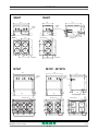
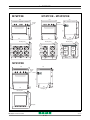
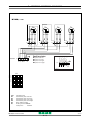
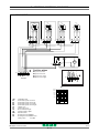
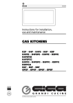
High Technology Low Cost
0801_GB_99
Instructions for installation,
use e maintenance
ELECTRIC KITCHENS
M62P · M64P · M62V · M64V
M74P · M74PQ · M76P · M72V · M74V
M74PFXE · M74PQFXE · M76PFXE
M74VFXE
03/2007
CHARACTERISTICS
Supplied by:
Date:
Customer Service:
FAX
e-mail
0801_GB_99 - ELECTRIC KITCHENS
03/2007
2 · 20
INDEX
1
Diagram
4
2
Characteristics of the appliances
7
3
Technical data
7
4 Installation instructions
4.1 Safety rules
4.2 Structure, framework and safety devices of the appliances
4.2.1 Oven
Electric version GN 1/1 ventilated
4.3 Assembly
4.3.1 Installation premises
4.3.2 Statutory regulations and technical requirements
4.3.3 Installation
4.3.4 Electrical connection
4.3.5 Equipotential
8
8
8
8
8
8
8
8
8
8
9
5 Operation preparation
5.1 Preparation and Start-up
5.1.1 Start-up
5.1.2 Operator training
5.2 Maintenance
5.3 Replacing parts
5.3.1 Heating element of electric oven GN 1/1
5.3.2 Fan electric oven GN 1/1
9
9
9
9
9
9
9
9
6 Instructions for use
6.1 Safety, cleaning and repair rules
6.2 Start-up
6.2.1 Electricals plates and Pyroceram
6.3 Lighting and shutdown of electric oven GN 1/1
6.4 Turning the appliance off in case of breakdown
6.4.1 What to do in case of failure
6.4.2 What to do in case of prolonged period of disuse
6.5 Appliance care and frequency of maintenance
6.6 Recommendations for handling “stainless steel” industrial
kitchens
6.6.1 Useful information on “stainless steel”
6.6.2 Warnings and advice for maintenance of “stainless steel”
appliances
6.6.3 WEEE Directive
7
Appendix: Electrical diagram
10
10
10
10
11
11
11
11
11
11
11
11
12
13-19
0801_GB_99 - ELECTRIC KITCHENS
03/2007
3 · 20
1 - DIAGRAM
M64P
M62P
600
600
103
315
79
27
27
315
346
69
50
27
Electric power
430
535
86
30
546
Electric
power
240.8
Electric
power
Electric
power
27
60
400
Data plate
176.5
79
1.5
kW
600
2.0
kW
2.0
kW
245
2.0
kW
1.5
kW
178.5
600
1.5
kW
200
400
200
400
Data plate
M76P
Data plate
M74P - M74PQ
800
700
60
1000
Electric
power
150
690
678
Electric
power
79
45
710
79
300
300
276.5
178.5
178.5
200
200
2.0
kW
2.0
kW
200
400
800
1000
0801_GB_99 - ELECTRIC KITCHENS
178.5
2.0
kW
2.0
kW
700
2.0
kW
79
Electric power
276.5
2.0
kW
2.0
kW
245
2.0
kW
700
2.0
kW
245
2.0
kW
55
Data plate
79
Electric power
276.5
Electric power
545
45
200
2.6
kW
2.6
kW
2.6
kW
2.6
kW
700
79
45
910
245
45
200
400
200
800
03/2007
4 · 20
1 - DIAGRAM
M76PFXE
M74PFXE - M74PQFXE
800
700
60
1000
Electric
power
150
690
678
Electric
power
79
45
710
79
300
300
276.5
178.5
178.5
200
2.0
kW
2.0
kW
200
200
400
200
800
1000
178.5
2.0
kW
2.0
kW
700
2.0
kW
79
Electric power
276.5
2.0
kW
2.0
kW
245
2.0
kW
700
2.0
kW
245
2.0
kW
55
Data plate
79
Electric power
276.5
Electric power
545
45
2.6
kW
2.6
kW
2.6
kW
2.6
kW
700
79
45
910
245
45
200
400
200
800
M74VFXE
800
60
700
150
690
678
Electric
power
79
45
710
545
55
45
Data plate
79
700
Electric power
Data plate
800
0801_GB_99 - ELECTRIC KITCHENS
03/2007
5 · 20
1 - DIAGRAM
M64V
M62V
600
400
60
600
Electric
power
103
240.8
Electric
power
79
546
27
Electric power
27
346
Electric power
430
535
86
Data plate
600
79
600
79
69
50
27
30
79
400
600
Data plate
Data plate
M74V
M72V
800
400
700
60
27
Electric
power
150
690
678
Electric
power
79
45
710
79
45
45
310
545
55
45
Data plate
79
79
700
Electric power
700
Electric power
Data plate
800
Data plate
400
0801_GB_99 - ELECTRIC KITCHENS
03/2007
6 · 20
2 - CHARACTERISTICS OF THE APPLIANCES
These appliances are used for professional purposes.
Installation, repair and use must be carried out by expert personnel.
The data plate is located on the appliance and contains all the data
needed for installation.
Beware of inexpert handling.
CAT/KAT
GAS/GAZ
G30
G20
G25
II2H3B/P
P mbar
30
30
20
-
SE
II2H3+
P mbar
30
37
G31
20
-
IT
CH
PT
II2H3+
P mbar
28
37
20
-
ES
IE
GB
FI
DK
II2L3B/P
P mbar
30
30
-
25
NL
II2ELL3B/P
P mbar
50
50
20
20
DE
II2E+3+
P mbar
28
37
20
25
FR
BE
MOD.
II2H3B/P
P mbar
50
50
20
-
AT
CH
ART.
I2E
P mbar
-
-
20
-
LU
II2H3B/P
P mbar
30
30
-
-
EE
LV
LT
N.
II2H3+
P mbar
28
37
20
-
EE
LV
LT
Qn kW
MOD.
I3B/P
P mbar
30
30
-
-
NO
MT
CY
I3+
P mbar
28
37
-
-
CY
TIPO/TYPE
N.
m3/h
CZ
SK
SI
GR
IS
HU
Predisposto a gas: - Gas preset: - Prevu pour gaz:
Eingestelt für Gas: - Preparado para gas: - Geschuckt voor:
V AC
kW
Hz
MADE IN ITALY
THE APPLIANCE MUST BE CONNECTED IN COMPLIANCE WITH THE LAWS IN FORCE
AND INSTALLED IN A WELL-VENTILATED ROOM. READ THE INSTRUCTION MANUALS
BEFORE INSTALLING AND USING THE APPLIANCE.
THE APPLIANCE MUST BE INSTALLED BY QUALIFIED PERSONNEL.
3 - TECHNICAL DATA
Model
Description
Dimensions in mm. (LxDxH)
M62P
Electric range 2 plates
400 x 600 x 270
M64P
Electric range 4 plates
600 x 600 x 270
M62V
Electric pyroceramic range with 2 plates
400 x 600 x 270
M64V
Electric pyroceramic range with 4 plates
600 x 600 x 270
M74P
Electric range 4 plates - open compartment
800 x 700 x 900
M76P
Electric range 6 plates - open compartment
1000 x 700 x 900
M74PFXE
Electric range 4 plates - electric convection oven GN 1/1 multifunction
800 x 700 x 900
M76PFXE
Electric range 6 plates - electric convection oven GN 1/1 multifunction
1000 x 700 x 900
M74PQ
Electric range 4 square plates - open compartment
800 x 700 x 900
M74PQFXE
Electric range 4 square plates - electric convection oven GN 1/1 multifunction
800 x 700 x 900
M72V
Electric pyroceramic range with 2 plates - open compartment
400 x 700 x 900
M74V
Electric pyroceramic range with 4 plates - open compartment
800 x 700 x 900
M74VFXE
Electric pyroceramic range with 4 plates - electric convection oven GN 1/1 multifunction
800 x 700 x 900
TABLE 1
Model
Plates
round
Heating element
1200 1800 2300
Plates
square
Oven
2500 W
Total
Power
Voltage rating
Lead wire Section
M62P
-
-
-
1500 W
1
2000 W
1
2600 W
-
-
3.5 kW
400V 3N or 230V 3
5 x 1.5 mm2 or 4 x 2.5 mm2
M64P
-
-
-
2
2
-
-
7.0 kW
400V 3N or 230V 3
5 x 1.5 mm2 or 4 x 2.5 mm2
M62V
1
-
1
-
-
-
-
3.5 kW
400V 3N or 230V 3
5 x 1.5 mm2 or 4 x 2.5 mm2
400V 3N or 230V 3
5 x 1.5 mm2 or 4 x 2.5 mm2
M64V
2
1
1
-
-
-
-
6.5 kW
M74P
-
-
-
-
4
-
-
8.0 kW
400V 3N or 230V 3
5 x 2.5 mm2 or 4 x 4 mm2
M76P
-
-
-
-
6
-
-
12.0 kW
400V 3N or 230V 3
5 x 2.5 mm2 or 4 x 6 mm2
4
-
1
10.5 kW
400V 3N or 230V 3
5 x 2.5 mm2 or 4 x 4 mm2
M74PFXE
-
-
-
-
M76PFXE
-
-
-
-
6
-
1
14.5 kW
400V 3N or 230V 3
5 x 2.5 mm2 or 4 x 6 mm2
M74PQ
-
-
-
-
-
4
-
10.4 kW
400V 3N or 230V 3
5 x 2.5 mm2 or 4 x 4 mm2
M74PQFXE
-
-
-
-
-
4
1
12.9 kW
400V 3N or 230V 3
5 x 2.5 mm2 or 4 x 6 mm2
M72V
1
-
1
-
-
-
-
3.5 kW
400V 3N or 230V 3
5 x 1.5 mm2 or 4 x 2.5 mm2
M74V
2
1
1
-
-
-
-
6.5 kW
400V 3N or 230V 3
5 x 1.5 mm2 or 4 x 2.5 mm2
M74VFXE
2
1
1
-
-
-
1
9.0 kW
400V 3N or 230V 3
5 x 2.5 mm2 or 4 x 4 mm2
round plates
18
square plates 22x22
0801_GB_99 - ELECTRIC KITCHENS
03/2007
7 · 20
4 - INSTALLATION INSTRUCTIONS
4.1 Safety rules
4.3 Assembly
• Only a local gas utility technician is authorized to carry out gas
installations and connections. The statutory regulations (applied
in Germany VDE, Austria ÖVE, Switzerland SEV, etc.) and connection conditions performed by the gas utility must be strictly
observed.
• In compliance with international regulations, when connecting
the appliance to the mains power supply, a device with a minimum aperture of 3 mm between contacts must be fitted
upstream of the appliance, allowing omnipolar disconnection of
the appliance from the mains. Also, a high-sensitivity automatic
differential switch must be installed which protects against direct
or indirect contact with live electrical parts and against current
leakage (maximum current leakage permissible by regulations is
1 mA/kW).
• Connection to a power balance system for the installation in a all
is given through a connection point. Follow the VDE 0100 T 410
connection rules or local rules.
• Compare technical datas on grey stickers to those written on this
manual and present power supply.
• Do not bend, crush or damage the cables against sharp corners.
• Lay the cables so as to avoid contact with extremely hot surfaces.
• Connection to the grid must be carried out with at least a cable
type NYM or H07RN-F.
• The cable - which is totally sheathed – must be led inside the
appliance through the cable clamp and cable raceway installed
on the appliance.
• Ventilation system installation can be carried out only by expert
personnel.
• If the appliance is to be installed near walls, dividing walls, kitchen equipment or decorative panelling, these should be in noninflammable material. If not, all appliances must be coated with
thermal-insulation fireproof material. Make sure that all fire prevention standards and safety precautions are strictly adhered to.
4.3.1 Installation premises
4.2 Structure, equipment and safety devices
of the unit
The appliance must be installed in a well-ventilated room, and if
possible under a range hood (check current regulations).
The appliance can be installed on its own or with other similar
equipment.
If the appliance is to be installed near inflammable walls, a minimum
distance of 150 mm around the sides and back should be allowed.
If this distance cannot be obtained, take proper heat-protection
action such as fitting tiles or thermal radiation protection material
to the walls.
4.3.2 Statutory regulations and technical requirements
During installation of the appliance, the following regulations must
be adhered to:
• Relevant legal directives;
• Local building and combustion regulations;
• "Technical rules for gas systems" worksheet;
• "Technical rules for liquid gas" worksheet;
• “Gas installations in industrial kitchens” worksheet;
• Relative accident prevention standards;
• Local gas utility regulations;
• Local building and fire codes.
4.3.3 Installation
Installation, start-up and maintenance should only be carried out by
expert personnel.
All work required to install the appliance should be carried out in
compliance with all local standards and regulations.
The manufacturers decline all responsibility where poor performance is due to incorrect installation in disregard of the above conditions.
4.3.4 Electrical connection
Robust steel frame, with 4 height adjustable feet.
Steel outer panelling.
Electric round plates made of cast-iron or pyroceram.
4.2.1 Oven
The cooking chamber is made of stainless steel.
The runners for the pans are made of chromium-plated steel.
Extractable chromium-plated steel grill..
The door, with double wall and thermal insulation, is equipped with
an insulated handle and a hinge with balanced spring.
The insulation of the cooking chamber is rockwool.
Electric version GN 1/1 ventilated
Before connecting the unit to the mains, check that:
• The mains voltage corresponds to the values shown on the data
plate;
• The earth is in working order;
• The power cord is suitable to the electrical input of the appliance (see table 1 pag. 7) and approved. The cord must be at
least type H07 RN-F.
The ground wire must be long enough to prevent tug after the
cable lead wires in case of raceway breakage.
Also, up the line from the unit, there must be a device with contact
opening of at least 3 mm which makes it possible to disconnect the
appliance in omnipolar mode.
To this end, for example, safety contactors may be used.
The omnipolar switch must be located near the appliance and be
readily accessible.
The heating element is place in the rear around the fan and is protected by a bulkhead. Temperature adjustment between 50°C and
300°C is made by a thermostat connected to a switch.
The lighting of the heating element is indicated by 2 indicator lights.
0801_GB_99 - ELECTRIC KITCHENS
03/2007
8 · 20
4 - INSTALLATION INSTRUCTIONS
4.3.5 Equipotential
The appliance must be hooked up to a unipotential system.The
required terminal is located near the power cable and it is marked
by a tag with a symbol
.
The manufacturers cannot be held responsible for any damage due to inadequate or incorrect installation. Under such
circumstances the guarantee will be considered null and void.
5 - SET-UP FOR OPERATION
5.1 Preparation and Start-up
5.3.2 Fan of of electric oven GN 1/1
Before starting up the appliance, remove the protective wrapping.
Then carefully clean the working surface and the external parts with
lukewarm water and detergent, using a damp rag to remove all traces
of anti-rust material applied in the factory, then dry with a clean cloth.
5.1.1 Start-up
To start up the appliance, see the instructions for regular use.
Unplug the appliance from the electrical mains!
To replace the fan remove the back unscrew the sight screws, disconnect the wires from the motor, from the inside of the chamber
remove the rear bulkhead fan cover and the fan (pos. 1 fig. 2) by
loosening the locking nut (pos. 2 fig. 2 “NB. the nut is with left
thread”).
Loosen the bolts (pos. 3 fig. 2) hat hold the motor (pos. 4 fig. 2) on
the oven and pull off from rear. Re-install in reverse order positioning in the correct way the seal protection (pos. 5 fig. 2) and power
mains.
5.1.2 Operator training
• Explain and show the user how the machine works according to
the instructions, and hand him this manual.
• Remind the user that any structural alterations or any building
modification or renovation may affect the combustion air supply,
thus requiring a second operation check.
After any maintenance or repair work, replace the control panel and the lower panel.
5.2 Maintenance
Attention! Before doing any repair or maintenance
work, unplug the appliance.
• Never leave the hotplates on unused!
• Only use flatbottomed pots and pans, and make sure that the
diameter of the pan is never smaller than the diameter of the
hotplate it is being used on.
5.3 Replacing parts
All parts must be replaced by authorized technicians
only!
To replace the following parts first remove all the control knobs and
control panel (after loosening the fixing screws), then extract the
ignition wire.
5.3.1 Heating element of electric oven GN 1/1
Unplug the appliance from the electrical mains!
To remove the heating element (pos. 6 fig. 2), remove the rear bulkhead, unscrew the screws fixing the the heating element to the
oven, pull the heating element forward with relative wires.
Disconnect the wires, and install a new heating element in reverse order.
0801_GB_99 - ELECTRIC KITCHENS
03/2007
9 · 20
6 - INSTRUCTIONS FOR USE
6.1 Safety, cleaning and repair rules
Fig. 1
• This appliance is used for the preparation of meals at industrial level. Usage and cleaning can be carried only by expert personnel. Maintenance and repair can be carried out only by
skilled technical personnel.
• These indications must be communicated to all those concerned during internal training.
• Attention! This appliance must be constantly watched over
when being used!
• Grease and overheated oil can catch fire. Use this appliance
only under constant control. Never use water to put out
grease or oil! Cover with a lid, turn off the hot plate and
remove pot from the burner.
• Do not overload the kitchen. For proper use, pots should
not be bigger than the flames.
• Parts of the appliance and attachments exposed to food
must be cleaned with detergents and rinsed thoroughly with
potable water.
• Do not clean the appliance using water jets or steam,
whether direct or pressurized!
• If the room is being cleaned with water/steam jets or high-pressure equipment, it is necessary to switch off the appliance first!
• Before starting to clean the appliance, disconnect from the
mains.
• Do not use inflammable liquid to clean the appliance.
• Repairs may be carried out only by skilled personnel.
2
1
6.2 Start-up
6.2.1 Electricals plates and Pyroceram
Turn on the main switch upstream of the appliance.
Turn the knob (pos. 1 fig. 1) on the selected plate to the required
position from 1 to 6. The green indicator light (pos. 2 fig. 1) will
indicate the heating element is on.
We advise first turning the hotplate up to maximum temperature.
Once this has been reached, turn the knob to the required heat.
To turn any plate off, simply turn the knob back to "0".
6 to begin cooking max. 5/10 min;
• During repairs, the appliance must undergo voltage
omnipolar insulation (local switch, i.e. safety load cut-off
switch).
• Noise emission values of the appliance in operation are below
70dB (A). This value is compulsory according to certain national
safety standards.
WARNING
Attention! The manufacturer declines all responsibility concerning mistakes included in these instructions due to translating or
printing errors: the manufacturer also reserves the right to
change the product as he see fits, though without changing its
essential features. The manufacturer declines all responsibility for
any non-compliance with the provisions contained in this manual.
Fig. 2
2
5 for high temperature cooking;
4 for medium temperature cooking;
3 to continue cooking large quantities;
2 to continue cooking small quantities;
1 to keep food hot or melt butter;
0 plate off.
Fig. 2A
3
4
5
1
6
2
0801_GB_99 - ELECTRIC KITCHENS
1
3
03/2007
10 · 20
6 - INSTRUCTIONS FOR USE
6.3 Lighting and shutdown of electric oven
GN 1/1
With knob (pos. 1 fig. 2A) turn the thermostat from the “0” position
to a desired temperature between 50°C and 300°C; the indicator
light will come on; the green one (pos. 2 fig. 2A) shows that the
appliance is on, the yellow one (pos. 3 fig. 2A) indicates that the
resistances are operational, as soon as the set-up temperature is reached, the indicator light goes off.
To turn the appliance off, turn the knob to position “0”.
6.4 Turning the appliance off in case of
breakdown
6.4.1 What to do in case of failure
In case of breakdown or malfunctioning or failure turn off the plates
and the oven. Switch off any electric power. Call the service centre.
6.4.2 What to do in case of prolonged period of disuse
When the appliance is not to be used for a long time, clean thoroughly, cas instructed in the chapter 6.5 “Appliance care and frequency of maintenance”, switch off any electric power.
6.5 Appliance care and frequency of maintenance
Attention! When cleaning, carefully avoid washing the
appliance with direct water jets or high-pressure
water!
Cleaning must be performed when the appliance is cold.
Thorough daily cleaning of the appliance, after disconnecting it, will
keep it in perfect working order and make it last longer. All steel
parts should be cleaned with water and a detergent, using a damp
cloth; do not use abrasive substances or corroding detergents.
Do not use steel wool, which could cause rust to form.
For the same reason, avoid touching the appliance with anything
made of iron. Do not clean with sandpaper and lubricating gel paper.
If absolutely necessary, you may use pumice powder.
If the appliance is extremely dirty, use a synthetic sponge (i.e.
Scotchbrite sponge).
After cleaning the appliance, rinse with clean water and wipe with a
clean cloth.
All maintenance and repair work must be carried out by authorized
technicians only.
The appliance must be checked at least once a year. For this reason,
a service agreement contract is recommended.
6.6 Recommendations for the treatment of
stainless “steel industrial” kitchens
6.6.1 Useful information on “stainless steel”
Industrial kitchens are generally made of “stainless steel” having the
following material codes:
• 1.4016 or 1.4511 = magnetizable chromed steels
• 1.4301, 1.4401 and 1.4571 = non-magnetizable chromed steels
Chromed steels have favourable thermo-technical characteristics. In
fact, they have less of a tendency to warp due to the effect of heat.
Chrome-nickel steels, instead, have good corrosion resistance features.
“Stainless steel” corrosion resistance is given by an inactive coat that
builds up on the surface by coming into contact with oxygen.
The oxygen in the air is already enough to build up the inactive coat
that allows automatic removal of anomalies and damage due to
mechanical actions. The inactive coat builds up or re-builds up faster
if the steel comes in contact with running water containing oxygen.
A more powerful effect is given by oxidative acids (nitric acid, oxalic
acid). These acids are used if the steel has undergone strong chemical stresses, hence generally losing its inactive coat.
The inactive layer can be chemically damaged or jeopardized by
reducing agents (oxygen consumption) if they come in contact with
the steel, concentrated or at high temperatures. These active substances include for instance:
• saline and sulphurous substances
• chlorides (salts)
• concentrated spices such as mustard, vinegar essences, soup
cubes, kitchen salt solutions, etc.
More damage can be caused by:
• outside rust (i.e. from other components, tools or incipient rust)
• iron particles (i.e. file dust)
• contact with non-ferrous metals (element build up)
• lack of oxygen (i.e. no air inlet, water lacking oxygen).
6.6.2 Warnings and advice for maintenance of “stainless steel” appliances
• “Stainless” steel equipment surfaces must be kept clean and in
contact with air at all times. When not running, keep appliance
doors open so as to allow air to run through it.
• Regularly remove calcium , grease, starch, and egg white
deposits where rust may build up if there is lack of air. Do not
use bleaching products or products containing chloride. Follow
all indications given by the company concerning special soaps
and cleaning methods to be used for the appliance. If no specific
cleaning recommendations are available, it is necessary, however,
to use detergents having a low chloride content. After cleaning,
remove all soap residues with plenty of clean water and thoroughly dry the surfaces.
• Minimize contact of “stainless steel” with concentrated acids,
spices, salts, etc. Even acid vapours coming from cleaning the
tiles favour “stainless steel” corrosion.
• Particularly for pots and multiple appliances, it is not recommended to load the cooking chamber only with food having a
high salt content.
It is preferable to cook different food together, i.e. fatty dishes
or vegetables containing acids.
• Avoid damaging the “stainless steel” surface, in particular with
different metals. Residues from other metals help build up the
formation of chemical microelements that may cause rust. At
any rate, it is appropriate to avoid contact between iron and
steel since it produces rust. Any contact between “stainless
steel” and iron (steel wool, pipeline chips, chalybeate waters)
can start corrosion phenomena.
• As for mechanical cleaning, it is recommended to use only steel
wool or natural, plastic or steel bristle brushes. Steel wool or
brushes with “stainless steel” can cause rust due to rubbing.
Newly formed rust spots can be removed with slightly abrasive liquid soaps or fine-grained sand paper. Larger rust spots can be
removed with 2-3% of hot oxalic acid solution. If these cleaning
products do not do the job, a nitric acid (10%) treatment is
required.
Attention! These treatments can be carried out only by
expert personnel according to current regulations!
0801_GB_99 - ELECTRIC KITCHENS
03/2007
11 · 20
6 - INSTRUCTIONS FOR USE
6.6.3 The 2002/96/EC (WEEE) Directive:
information to users
Fig. A
This informational note is meant only
for owners of equipment marked with
the symbol shown in fig. A on the adhesive label featuring the technical specifications applied on the actual product
(the label also giving the serial number).
This symbol indicates that the product is classified, according to the
regulations in force, as an item of electrical and electronic equipment and conforms to EU Directive 2002/96/EC (WEEE) meaning
that, at the end of its service life, it must be treated separately from
domestic waste, i.e. it must be handed in free of charge to a separate waste electrical and electronic equipment collection centre or
returned to the reseller when buying a new equivalent item of
equipment.
The user is responsible for delivering the unit at the end of its life
to the appropriate collection facilities. Failure to do so shall result in
the user being subject to the penalties prescribed by the legislation
in force on waste.
Suitable separated collection so that the unit no longer used can be
sent off for environmentally compatible recycling, treatment and
disposal helps avoid possible negative effects on the environment
and on health and facilitates the recycling of the product's component materials.
For more detailed information on available collection systems, contact the local waste disposal service or the shop you purchased the
unit from.
Producers and importers fulfil their responsibility for environmentally compatible recycling, treatment and disposal both directly and by
joining a collective scheme.
NOTES
0801_GB_99 - ELECTRIC KITCHENS
03/2007
12 · 20
7 - APPENDIX: ELECTRICAL DIAGRAMS
M62P M62V M72V -
1xR1 + 1xR2
1xR3 + 1xR4
1xR1 + 1xR2
400V 3N
Position plates
B1 plate rear
B2 plate front
230V 3
1200 w
6
2300 w
6
5
700 w
5
1200 w
5
4
340 w
4
600 w
4
300 w
3
340 w
3
600 w
3
2
220 w
2
170 w
2
300 w
2
1
175 w
1
125 w
1
230 w
1
6
2000 w
6
1150 w
5
1150 w
850 w
4
850 w
300 w
3
220 w
135 w
5 2 1 3 3 4
P3
P1
P2
0
0
0
0
mA
B1
B2
H1
R1
R2
R3
R4
R4
R3
R2
R1
1500 w
5 2 1 3 3 4
5 2 1 3 3 4
P3
P1
P3
P2
P1
P2
5 2 1 3 3 4
P3
P1
P2
Terminal board
Commutator plate rear
Commutator plate front
Green indicator light
Heating element 1500 W
Heating element 2000 W
Heating element 1200 W pyroceram
Heating element 2300 W pyroceram
Total power: 3.5 kW
0801_GB_99 - ELECTRIC KITCHENS
03/2007
13 · 20
7 - APPENDIX: ELECTRICAL DIAGRAMS
M64P
M64V
M74P
M74V
-
2xR1 + 2xR2
2xR3 + 1xR4 + 1xR5
4xR2
2xR3 + 1xR4 + 1xR5
R...
R...
1 2
4 3
2 1
3 4
1 2
4 3
2 1
3 4
R...
R...
1 2
4 3
2 1
3 4
1 2
4 3
2 1
3 4
P1
P2
H1
5
B1
5
5
B2
P3
P1
P2
P3
P1
P2
B4
P3
P1
P2
Position plates
400V 3N
mA
1
2
3
4
5
L1 L2 L3 N
PE
P3
B1
B1
B2
B2
B1 plate rear left
B2 plate front left
B3 plate rear right
B4 plate front right
6
5
B3
B3
B3
B4
B4
mA
1
2
3
4
L1 L2 L3
5
6
PE
230V 3
R4
R3
R2
R1
R5
1200 w
6
1800 w
6
2300 w
6
5
700 w
5
1000 w
5
1200 w
5
4
340 w
4
500 w
4
600 w
4
300 w
3
340 w
3
500 w
3
600 w
3
2
220 w
2
170 w
2
250
0w
2
300 w
2
1
175 w
1
125 w
1
180
0w
1
230 w
1
1500 w
6
2000 w
6
1150 w
5
1150 w
850 w
4
850 w
300 w
3
220 w
135 w
5 2 1 3 3 4
P3
mA
B1
B2
B3
B4
H1
R1
R2
R3
R4
R5
P1
P2
0
0
0
0
5 2 1 3 3 4
P3
P1
P2
5 2 1 3 3 4
P3
P1
P2
0
5 2 1 3 3 4
P3
P1
P2
5 2 1 3 3 4
P3
P1
P2
Terminal board
Commutator plate rear left
Commutator plate front left
Commutator plate rear right
Commutator plate front right
Green indicator light
Heating element 1500 W
Heating element 2000 W
Heating element 1200 W pyroceram
Heating element 1800 W pyroceram
Heating element 2300 W pyroceram
Total power:
M64P 7.0 kW
M64V - M74V 6.5 kW
M74P 8.0 kW
0801_GB_99 - ELECTRIC KITCHENS
03/2007
14 · 20
7 - APPENDIX: ELECTRICAL DIAGRAMS
M74PFXE M74VFXE -
4xR1 + 1xR6
2xR3 + 1xR4 + 1xR5 + 1xR6
R...
R...
1 2
4 3
2 1
3 4
1 2
4 3
2 1
3 4
R...
R...
1 2
4 3
2 1
3 4
1 2
4 3
2 1
3 4
P1
P2
H1
5
B1
5
5
B2
P3
P1
P2
5
B3
P3
P1
P2
B4
P3
P1
P2
H2
H1
1
2
P3
MV
11
A1
P1 P2
12
Position plates
mA
1
2
3
4
5
L1 L2 L3 N
6
PE
R6
F1
B1
B1 plate rear left
B2 plate front left
B3 plate rear right
B4 plate front right
A1
A1
B2
B2
B1
B3
B3
B4
B4
mA
1
2
3
4
5
6
400V 3N
L1 L2 L3
PE
230V 3
R3
R1
mA
B1
B2
B3
B4
A1
F1
H1
H2
MV
R1
R3
R4
R5
R6
Terminal board
Commutator plate rear left
Commutator plate front left
Commutator plate rear right
Commutator plate front right
Switch oven
Thermostat oven
Green indicator light
Yellow indicator light
Motorized fan
Heating element 2000 W
Heating element 1200 W pyroceram
Heating element 1800 W pyroceram
Heating element 2300 W pyroceram
Heating element 2500 W oven
6
1150 w
5
700 w
5
850 w
4
340 w
4
300 w
3
340 w
3
220 w
2
170 w
2
175 w
1
125 w
1
0
0
5 2 1 3 3 4
5 2 1 3 3 4
P3
P1
P3
P2
R4
M74PFXE 10.5 kW
M74VFXE 9.0 kW
6
2300 w
6
1000 w
5
1200 w
5
500 w
4
600 w
4
500 w
3
600 w
3
250
0w
2
300 w
2
180
0w
1
230 w
1
P2
0
5 2 1 3 3 4
P3
0801_GB_99 - ELECTRIC KITCHENS
P1
R5
1800 w
0
Total power:
6
2000 w
1200 w
P1
P2
5 2 1 3 3 4
P3
P1
P2
03/2007
15 · 20
7 - APPENDIX: ELECTRICAL DIAGRAMS
M76P -
6xR1
R1
R1
1 2
4 3
2 1
3 4
1 2
4 3
2 1
3 4
R1
R1
R1
1 2
4 3
2 1
3 4
1 2
4 3
2 1
3 4
R1
1 2
4 3
2 1
3 4
1 2
4 3
2 1
3 4
H1
5
5
B1
B2
P3
P1
P2
5
B3
P3
P1
P2
5
P3
P1
P2
5
P3
P1
P2
B6
P1
P3
Position plates
B1 plate rear left
B2 plate front left
B3 plate rear central
B4 plate front central
B5 plate rear right
B6 plate front right
5
B5
B4
P2
B1
P3
B2
B2
B3
B4
B4
B5
B5
B6
B6
1
2
3
4
L1 L2 L3
mA
1
2
3
4
L1 L2 L3 N
5
5
6
PE
230V 3
6
PE
P2
B1
B3
mA
P1
400V 3N
R1
2000 w
6
1150 w
5
850 w
4
300 w
3
220 w
2
175 w
1
0
5 2 1 3 3 4
P3
mA
B1
B2
B3
B4
B5
B6
H1
R1
P1
P2
Terminal board
Commutator plate rear left
Commutator plate front left
Commutator plate rear central
Commutator plate front central
Commutator plate rear right
Commutator plate front right
Green indicator light
Heating element 2000 W
Total power: 12.0 kW
0801_GB_99 - ELECTRIC KITCHENS
03/2007
16 · 20
7 - APPENDIX: ELECTRICAL DIAGRAMS
M76PFXE -
6xR1 + 1xR6
R1
R1
1 2
4 3
2 1
3 4
1 2
4 3
2 1
3 4
R1
1 2
4 3
2 1
3 4
R1
R1
1 2
4 3
2 1
3 4
R1
1 2
4 3
2 1
3 4
1 2
4 3
2 1
3 4
H1
5
5
B1
B2
P3
P1
P2
5
5
B3
P3
P1
P2
5
P3
P1
P2
P3
P1
B6
P3
P2
P1
P2
1
2
4
L1 L2 L3 N
5
6
PE
400V 3N
B1 plate rear left
B2 plate front left
B3 plate rear central
B4 plate front central
B5 plate rear right
B6 plate front right
R6
12
Position plates
3
P2
F1
P1 P2
2
P1
MV
11
A1
1
P3
H2
H1
mA
5
B5
B4
B1
A1
A1
B2
B2
B1
B3
B3
B4
B4
B5
B5
B6
B6
mA
1
2
3
4
L1 L2 L3
5
6
PE
230V 3
R1
mA
B1
B2
B3
B4
B5
B6
A1
F1
H1
H2
MV
R1
R6
Terminal board
Commutator plate rear left
Commutator plate front left
Commutator plate rear central
Commutator plate front central
Commutator plate rear right
Commutator plate front right
Switch oven
Thermostat oven
Green indicator light
Yellow indicator light
Motorized fan
Heating element 2000 W
Heating element 2500 W oven
2000 w
6
1150 w
5
850 w
4
300 w
3
220 w
2
175 w
1
0
5 2 1 3 3 4
P3
P1
P2
Total power: 14.5 kW
0801_GB_99 - ELECTRIC KITCHENS
03/2007
17 · 20
7 - APPENDIX: ELECTRICAL DIAGRAMS
M74PQ -
4xR1
R1
R1
1 2
4 3
2 1
3 4
R1
1 2
4 3
2 1
3 4
R1
1 2
4 3
2 1
3 4
1 2
4 3
2 1
3 4
P1
P2
H1
5
B1
5
B2
P3
P1
P2
5
P3
P1
P2
B4
P3
P1
P2
Position plates
400V 3N
mA
1
2
3
4
L1 L2 L3 N
5
6
PE
5
B3
B1 plate rear left
B2 plate front left
B3 plate rear right
B4 plate front right
P3
B1
B1
B2
B2
B3
B3
B4
B4
mA
1
2
3
L1 L2 L3
4
5
6
PE
230V 3
R1
2600 w
6
1800 w
5
1200 w
4
600 w
3
400 w
2
270 w
1
0
B1
5 2 1 3 3 4
P3
mA
B1
B2
B3
B4
H1
R1
P1
P2
Terminal board
Commutator plate rear left
Commutator plate front left
Commutator plate rear right
Commutator plate front right
Green indicator light
Heating element 2600 W
Total power:
10.4 kW
0801_GB_99 - ELECTRIC KITCHENS
03/2007
18 · 20
7 - APPENDIX: ELECTRICAL DIAGRAMS
M74PQFXE -
4xR1 + 1xR6
R1
R1
1 2
4 3
2 1
3 4
R1
1 2
4 3
2 1
3 4
R1
1 2
4 3
2 1
3 4
1 2
4 3
2 1
3 4
P1
P2
H1
5
B1
5
5
B2
P3
P1
P2
5
B3
P3
P1
P2
B4
P3
P1
P2
H2
H1
1
2
P3
MV
11
A1
P1 P2
12
Position plates
mA
1
2
3
4
5
L1 L2 L3 N
6
PE
R6
F1
B1
B1 plate rear left
B2 plate front left
B3 plate rear right
B4 plate front right
A1
A1
B2
B2
B1
B3
B3
B4
B4
mA
1
2
3
4
5
6
400V 3N
L1 L2 L3
PE
230V 3
R1
mA
B1
B2
B3
B4
A1
F1
H1
H2
MV
R1
R6
6
1800 w
5
1200 w
4
600 w
3
400 w
2
270 w
1
0
Terminal board
Commutator plate rear left
Commutator plate front left
Commutator plate rear right
Commutator plate front right
Switch oven
Thermostat oven
Green indicator light
Yellow indicator light
Motorized fan
Heating element 2600 W
Heating element 2500 W oven
Total power:
2600 w
B1
5 2 1 3 3 4
P3
P1
P2
12.9 kW
0801_GB_99 - ELECTRIC KITCHENS
03/2007
19 · 20
WARNING
THE MANUFACTURER CANNOT BE HELD RESPONSIBLE
FOR ANY INACCURACIES IN THIS BOOKLET DUE
TO COPYING OR PRINTING ERRORS.
DUE TO ITS POLICY OF CONTINUAL PRODUCT IMPROVEMENT,
THE MANUFACTURER RESERVES THE RIGHT
TO MAKE ANY CHANGES DEEMED NECESSARY.
THE MANUFACTURER CANNOT BE HELD RESPONSIBLE
IF THE INSTRUCTIONS CONTAINED IN THIS MANUAL
ARE NOT OBSERVED.
GIGA Grandi Cucine S.r.l. - Via Pisana, 336 - 50018 Loc. Olmo di Scandicci (FI) - Italy
Tel. +39 055 722 33 (11 linee r.a.) - Fax +39 055 7310056
www.gigagrandicucine.it - [email protected]