1
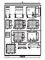
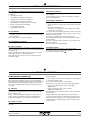
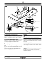
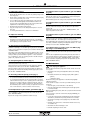
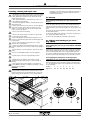
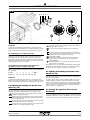
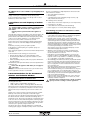
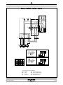
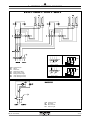
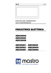
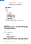
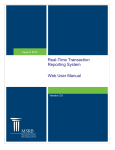
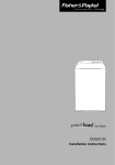
011_03
Instructions for installation,
use and maintenance
GAS KITCHENS
K2F · K4F · K4FS · K6F · K8F
K4FFE · K4FSFE · K6FFE · K8FFE
K4FSFCE
K4FSFCG
K4FFG · K4FSFG · K6FFG · K8FFG
K6FFGA
B4F · B6F · B8F
OP2F · OP4F · OP6F · OP8F
© COPYRIGHT 2004 GIGA GRANDI CUCINE SRL
07/2009
CHARACTERISTICS
Supplied by:
Date:
Customer Service:
FAX
e-mail
011_03 - GAS KITCHENS
07/2009
2 · 22
INDEX
1
Diagram
4
2
Features of the appliances
7
3
Technical data
7-8
4 Installation instructions
4.1 Safety rules
4.2 Structure, equipment and safety devices of the appliances
4.2.1 Cooking zone
4.2.2 Oven
Gas version GN 2/1 and MAXI
Gas version GN 1/1 ventilated
Electric version GN 2/1
Electric version GN 1/1 ventilated
4.2.3 Neutral cabinet
4.3 Assembly
4.3.1 Installation premises
4.3.2 Statutory regulations and technical requirements
4.3.3 Installation
4.3.4 Installation operations
4.3.5 Gas connection
4.3.6 Smoke extraction
4.3.7 Electrical connection
4.3.8 Equipotential
9
9
9
9
9
9
9
9
9
9
9
9
10
10
10
10
10
10
10
5 Operation preparation
5.1 Preparation and Start-up
5.1.1 Start-up
5.1.2 Check of power
5.1.3 Checking the input pressure
5.1.4 Power check with volumetric method
5.1.5 Power check for operation with liquid gas
5.1.6 Check of pilot flame
5.1.7 Checking the primary air
5.1.8 Operation Control
5.1.9 Operator training
5.1.10 Conversion and adjustment
5.1.11 Replacement of burner nozzles
5.1.12 Setting reduced capacity power
5.1.13 Replacement of pilot nozzle (open flames)
5.1.14 Replacement of pilot nozzle (gas oven GN 2/1)
5.1.15 Replacement of pilot nozzle (gas oven MAXI)
5.1.16 Replacement of nozzle of gas ovens GN 1/1 and MAXI
5.1.17 Replacement of burner nozzle (gas oven)
5.2 Maintenance
5.3 Replacing parts
5.3.1 Gas valve (open flames)
5.3.2 Thermocouple (open flames)
5.3.3 Plug (gas oven)
5.3.4 Gas valve (gas oven)
5.3.5 Thermocouple (gas oven)
5.3.6 Main burner (gas oven)
5.3.7 Heating elements (electric oven GN 1/1)
5.3.8 Heating elements (electric oven GN 2/1)
5.3.9 Fan for electric and gas ovens GN 1/1
10
10
10
10
11
11
11
11
11
13
13
13
13
13
13
13
13
13
13
13
14
14
14
14
14
14
14
14
14
14
6 Instructions for use
6.1 Safety, cleaning and repair rules
14
14
6.2 Start-up
6.2.1 Lighting and disconnecting open flame burner
6.3 Lighting and shutting down a gas oven
6.3.1 Lighting the pilot (gas oven GN 1/1)
6.3.2 Lighting the pilot (gas oven GN 2/1 and MAXI)
6.3.3 Lighting the main burner and temperature adjustment
(gas ovens GN 1/1)
Shutdown
6.3.4 Lighting the main burner and temperature adjustment
in gas oven GN 1/1
Shutdown
6.4 Lighting and shutdown of electric oven GN 1/1
6.5 Lighting and shutdown of electric oven GN 2/1
6.6 Turning the appliance off in case of breakdown
6.6.1 What to do in case of failure or prolonged period
of disuse
6.7 Appliance care and frequency of maintenance
6.8 Recommendations for handling stainless steel
industrial kitchens
6.8.1 Useful information on stainless steel
6.8.2 Warnings and advice for maintenance of stainless steel
appliances
6.8.3 WEEE Directive
15
15
15
15
15
7
011_03 - GAS KITCHENS
Appendix: Electrical diagrams
16
16
16
16
16
16
16
17
17
17
17
17
18
19-21
07/2009
3 · 22
1 - DIAGRAM
800
400
900
300
K4FFG
K4FFE
970
3/4"
K2F
3/4"
53
294
150
3/4"
21
21
53
53
100 150
21
53
694
52
706
K4F
K4FFG - K4FFE
K2F - OP2F
142
K4FS - K4FSFCG
K4FSFG - K4FSFCE - K4FSFE
295
295
6.4
kW
900
590
6.4
kW
680
8.3
kW
295
8.3
kW
680
590
8.3
kW
590
350
350
350
3/4"
4.3
kW
8.3
kW
3/4"
255 310
200
4.3
kW
8.3
kW
3/4"
255 310
220
200
200
400
255 310
220
200
200
900
275
310
6.4 kW
Ø 100 mm
200
400
B4F
4.3 kW
Ø 80 mm
8.3
kW
6.4
kW
3/4"
8.3
kW
590
B4F
8.3 kW
Ø 120 mm
350
900
3/4"
590
8.3
kW
3/4"
4.3
kW
275
3/4"
310
150
100
200
400
706
142
200
800
140
142
900
OP4F
295
340
OP4F
8.3
kW
350
900
8.3
kW
270
55
6.4
kW
53
694
53
35
4.3
kW
255
200
400
200
011_03 - GAS KITCHENS
07/2009
4 · 22
1 - DIAGRAM
1200
900
300
K6FFG
K6FFE
K6FFGA
970
3/4"
900
3/4"
150
21
100 150
21
53
1094
53
706
52
142
296
900
6.4
kW
680
6.4
kW
8.3
kW
590
350
4.3
kW
8.3
kW
4.3
kW
B6F
3/4"
310
220
255
900
3/4"
3/4"
200
400
400
200
K6F
K6FFG - K6FFE
K6FFGA
150
100
706
142
1200
142
900
340
270
55
OP6F
53
1094
35
53
140
OP6F
4.3 kW
6.4 kW
8.3 kW
296
6.4
kW
6.4
kW
8.3
kW
Ø 80 mm
Ø 100 mm
Ø 120 mm
350
900
4.3
kW
8.3
kW
4.3
kW
255
200
400
400
200
011_03 - GAS KITCHENS
07/2009
5 · 22
1 - DIAGRAM
1600
900
300
K8FFG
K8FFE
970
900
3/4"
3/4"
21
150
100 150
21
53
1494
52
53
142
706
296
6.4
kW
680
6.4
kW
6.4
kW
8.3
kW
900
590
350
8.3
kW
4.3
kW
8.3
kW
4.3
kW
3/4"
B8F
310
255
220
900
200
400
400
400
3/4"
200
3/4"
K8F
K8FFG - K8FFE
150
100
706
142
142
900
1600
340
270
55
OP8F
53
1494
53
35
140
OP8F
296
6.4
kW
6.4
kW
6.4
kW
8.3
kW
900
4.3 kW
6.4 kW
8.3 kW
Ø 80 mm
Ø 100 mm
Ø 120 mm
350
8.3
kW
4.3
kW
8.3
kW
4.3
kW
255
200
400
400
400
200
011_03 - GAS KITCHENS
07/2009
6 · 22
2 - CHARACTERISTICS OF THE APPLIANCES
These appliances are used for professional purposes. Installation,
repair and use must be carried out by expert personnel.
These instructions for installation are for our gas kitchens set up for
the category in the table on page 8.
The data plate is located on the front part of the appliance (on the
control panel).
CAT/KAT
GAS/GAZ
G30
G31
G20
II2H3B/P
P mbar
30
30
20
-
SE
FI
DK
II2H3+
P mbar
30
37
20
-
IT
CH
PT
II2H3+
P mbar
28
37
20
-
ES
IE
GB
II2L3B/P
P mbar
30
30
-
25
GB
0051 II2ELL3B/P
G25
P mbar
50
50
20
20
DE
TIPO/TYPE
II2E+3+
P mbar
28
37
20
-
FR
BE
MOD.
II2H3B/P
P mbar
50
50
20
-
AT
CH
ART.
I2E
P mbar
-
-
20
-
LU
N.
II2H3B/P
P mbar
30
30
-
-
EE
LV
LT
N.
II2H3+
P mbar
28
37
20
-
EE
LV
LT
Qn kW
MOD.
I3B/P
P mbar
30
30
-
-
NO
MT
CY
I3+
P mbar
28
37
-
-
CY
m3/h
CZ
SK
SI
GR
IS
HU
Predisposto a gas: - Gas preset: - Prevu pour gaz:
Eingestelt für Gas: - Preparado para gas: - Geschuckt voor:
V AC
KW
Hz
MADE IN ITALY
THE APPLIANCE MUST BE CONNECTED IN COMPLIANCE WITH CURRENT REGULATIONS AND
INSTALLED IN A WELL-VENTILATED ROOM. READ THE INSTRUCTION MANUAL BEFORE
INSTALLING AND USING THE APPLIANCE. THE APPLIANCE MUST BE INSTALLED BY QUALIFIED
PERSONNEL
G30/G31
G20
30/37 mbar
20 mbar
3 - TECHNICAL DATA
Model
Version
Dim.: LxWxH
N.
K2F
2 burners - open compartment
400 x 900 x 900/970
51BQ2899
OP2F
2 burners, embossed
400 x 900 x 270/340
51BQ2899
K4F • K4FS
4 burners - open compartment
800 x 900 x 900/970
51BQ2899
OP4F
4 burners, embossed
800 x 900 x 270/340
51BQ2899
K6F
6 burners - open compartment
1200 x 900 x 900/970
51BQ2899
OP6F
6 burners, embossed
1200 x 900 x 270/340
51BQ2899
K8F
8 burners - open compartment
1600 x 900 x 900/970
51BQ2899
OP8F
8 burners, embossed
1600 x 900 x 270/340
51BQ2899
K4FSFCG
4 burners - 1 gas oven GN 1/1 ventilated
800 x 900 x 900/970
51BQ2899
K4FFG • K4FSFG
4 burners - 1 gas oven GN 2/1
800 x 900 x 900/970
51BQ2899
K4FSFCE
4 burners - 1 electric oven GN 1/1 ventilated
800 x 900 x 900/970
51BQ2899
K4FFE • K4FSFE
4 burners - 1 electric oven GN 2/1
800 x 900 x 900/970
51BQ2899
K6FFG
6 burners - 1 gas oven GN 2/1 - cabinet
1200 x 900 x 900/970
51BQ2899
K6FFGA
6 burners - 1 gas oven MAXI
1200 x 900 x 900/970
51BQ2899
K6FFE
6 burners - 1 electric oven GN 2/1 - cabinet
1200 x 900 x 900/970
51BQ2899
K8FFG
8 burners - 2 gas oven GN 2/1
1600 x 900 x 900/970
51BQ2899
K8FFE
8 burners - 2 electric oven GN 2/1
1600 x 900 x 900/970
51BQ2899
B4F
4 burners - double controls - open compartment
800 x 900 x 900
51BQ2899
B6F
6 burners - double controls - open compartment
1200 x 900 x 900
51BQ2899
B8F
8 burners - double controls - open compartment
1600 x 900 x 900
51BQ2899
011_03 - GAS KITCHENS
07/2009
7 · 22
3 - TECHNICAL DATA
TABLE 1
Model
X
Ø 80
Y
Ø 100
Z
Ø 120
Gas oven
GN 1/1
Gas oven
GN 2/1
Gas oven
MAXI
Category
II2H3+
Construction type
A
Air necessary for combustion
m3/h
9
15
17
7.5
16
26.5
Nominal thermal power
kW
4.3
6.4
8.3
3.6
7.8
12.0
Minimum thermal power
kW
1.2
1.8
2.9
0.75
-
-
Overall thermal power (gas)
Hour consumption
G20
m3/h
G25
m3/h
G30/G31
kg/h
K2F • OP2F
11.2 kW
1,19
-
0,88
K4F • K4FFE • B4F • OP4F
28.3 kW
2,99
-
2,21
K6F • K6FFE • B6F • OP6F
39.5 kW
4,16
-
3,08
K8F • K8FFE • B8F • OP8F
54.7 kW
5,79
-
4,28
K4FFG
36.1 kW
3,81
-
2,82
K6FFG
47.3 kW
4,98
-
3,69
K8FFG
70.3 kW
7,44
-
5,50
K4FS • K4FSFE
34.2 kW
3,61
-
2,67
K4FSFG
42.0 kW
4,44
-
3,28
K4FSFCG
37.8 kW
3,99
-
2,95
K4FSFCE
34.2 kW
3,61
-
2,67
K6FFGA
51.5 kW
5,45
-
4,03
Connection pressure
Methane gas 2H
G20
20 mbar
Liquid gas 3+
G30/G31
28/37 mbar
Paramètres raccordement du gaz
Methane gas 2H
(HuB = 9.45 kWh/m3) in m3/h
0.455
0.677
0.878
0.421
0.825
1.375
Liquid gas 3+
(HuB = 12.87 kWh/kg) in kg/h
0.334
0.497
0.645
0.281
0.606
1.010
Nozzles Ø 1/100 mm
G20
Main burner
G30/31
Nominal thermal power
150
180
200
155
215
270
Minimal thermal capacity
Adjustable
Adjustable
Adjustable
Adjustable
-
-
Nominal thermal power
100
120
140
100
140
170
Minimal thermal capacity
45
55
80
48
-
-
G20
35
35
35
-
35
35
G30/G31
20
20
20
-
20
20
Methane gas G20
5
4
10
Open
12
3
Liquid gas G30/G31
8
9
12
Open
10
Open
No. of nozzles, pilot burner
Primary air distance “A”
Electrical data
Electric oven power:
Voltage:
No. of cables per section:
GN 2/1 - 5.9 kW
V 400 3N 50 Hz / 230 3 50 Hz
5 x 2.5 mm2 / 4 x 2.5 mm2
GN 1/1 - 2.5 kW
230 50 Hz
3 x 1.5 mm2
011_03 - GAS KITCHENS
07/2009
8 · 22
4 - INSTALLATION INSTRUCTIONS
4.1 Safety regulations
The smoke collector is in aluminised sheet metal and the protection
grill is in enamelled cast iron.
• Only a local gas utility technician is authorized to carry out gas
installations and connections. The statutory regulations (applied
in Germany VDE, Austria ÖVE, Switzerland SEV, etc.) and connection conditions performed by the gas utility must be strictly
observed.
• Connection to a power balance system for the installation in a
wall is provided for through a connection point. Adhere to current local legal requirements for connection.
• Please note the electrical diagram! Compare the wiring diagram
number on the data plate of the appliance with the one shown
on the electrical diagram.
• Do not bend, crush or damage the cables against sharp corners.
• Lay the cables so as to avoid contact with extremely hot surfaces.
• The cable – which is totally sheathed – must be led inside the
appliance through the cable clamp and cable raceway installed
on the appliance.
• Ventilation system installation can be carried only by expert personnel.
• If the appliance is to be installed near walls, dividing walls, kitchen
equipment or decorative panelling, these should be in non-inflammable material. If not, all appliances must be coated with thermalinsulation fireproof material. Make sure that all fire prevention
standards and safety precautions are strictly adhered to.
4.2 Structure, equipment and safety devices
of the unit
Robust steel frame, with 4 height adjustable feet.
18/10 chrome-nickel steel outer panelling.
Gas version GN 1/1 ventilated
The tubular burners are in stainless steel and are resistant to thermal and mechanical stress.
Gas is supplied through a safety valve with a thermostat and a safety thermocouple.
The ignition of the main burner takes place by means of an AT
transformer.
The adjustment of the oven temperature, which can be varied
between 160 and 300° C, is made with the thermostat.
The bottom of the oven is made of stainless steel.
The smoke collector is in aluminised sheet metal and the protection
grill is in enamelled cast iron.
Electric version GN 2/1
The heating elements are in the top (upper heat) and under the
bottom (lower heat).
Temperature adjustment between 50 and 300° C is made by a thermostat connected to a tri-polar switch.
It is possible to turn on the upper and lower heating elements separately or at the same time.
Indicator lights show when voltage is supplied to the appliance (see
Fig. 4A).
The cooking chamber is made of stainless steel.
The upper heating elements are visible (grill), while the lower ones
are covered by a sheet of stainless steel.
Electric version GN 1/1 ventilated
4.2.1 Cooking zone
•
•
•
•
•
Burner with stabilized flame.
Gas cocks with safety and adjustable from maximum to minimum.
Thermoelectric ignition safety.
Enamelled cast-iron pan supports.
The bodies of the burners and the venturi tubes are made of cast
iron, while the lid is brass
• 18/10 chrome-nickel steel cooking top.
• Knobs in thermosetting material.
The heating elements are in the top (upper heat), under the bottom
(lower heat), and in the rear around the fan (convection).
The upper heating elements are visible (grill), while the lower ones
are covered by stainless steel panels.
Temperature adjustment between 50 and 300° C is made by a thermostat connected to a switch.
The use of a 9-position commutator makes it possible to light the
heating elements separately or at the same time with ventilation or
in static mode.
The lighting of the heating elements is indicated by 2 indicator
lights (see fig. 4B).
4.2.3 Neutral cabinet
4.2.2 Oven
The cooking chamber is made of stainless steel.
The runners for the pans are made of steel or chromed rod iron.
The pull-out grill is in chromed rod-iron.
The door, with double wall and thermal insulation, is equipped with
an insulated handle and a hinge with balanced spring.
The insulation of the cooking chamber is fibreglass.
Gas version GN 2/1 and MAXI
The tubular burners are in chromed steel and are resistant to thermal and mechanical stress.
Gas is supplied through a safety valve with a thermostat.
The main burner is switched on from a pilot burner with a fixed nozzle. It is also equipped with a thermoelectric ignition safety with a
thermocouple connected to the pilot burner. The burner has a piezo
ignition.
The adjustment of the oven temperature, which can be varied
between 160 and 300° C, is made with the thermostat.
The bottom of the oven, in cast iron with reinforced ribs (for GN 2/1)
and steel (for MAXI), is in two pieces.
In models K6FFG, K6FFE, a neutral cabinet with a door alongside the
oven is standard.
4.3 Assembly
4.3.1 Installation premises
The appliance should be installed in a well-ventilated room, and if
possible under a range hood (check current regulations).
The appliance can be installed on its own or with other similar
equipment.
If the appliance is to be installed near inflammable walls, a minimum distance of 150 mm around the sides and back should be
allowed.
If this distance cannot be obtained, take proper heat-protection
action such as fitting tiles or thermal radiation protection material
to the walls.
Before connecting the appliance to the gas supply, check on the
data plate that the appliance is suitable and type-tested for the
type of gas available.
If not, see paragraph “Conversion and adjustment”.
011_03 - GAS KITCHENS
07/2009
9 · 22
4 - INSTALLATION INSTRUCTIONS
4.3.2 Statutory regulations and technical requirements
4.3.6 Smoke extraction
During installation of the appliance, the following regulations must
be adhered to:
• relevant legal directives;
• Local building and combustion regulations;
• "Technical rules for gas systems" worksheet;
• "Technical rules for liquid gas" worksheet;
• “Gas installations in industrial kitchens” worksheet;
• Relative accident prevention standards;
• Local gas utility regulations.
• Local building and fire codes.
These kitchens are type A appliances, thus no smoke extraction system is required.
For the ventilation of the room where the appliance is installed,
refer to related legislation.
4.3.3 Installation
Assembly, installation and maintenance, i.e.:
• assembly, gas connection, check of power, conversion or adaptation and start-up;
Ask for approval from the local gas company.
4.3.4 Installation operations
To level the appliance correctly, adjust the height of the feet.
4.3.5 Gas connection
The R 3/4” gas connection of the appliance to the gas pipeline can
either be permanently fixed to the mains or made detachable using
an approved cock.
If hoses are used, they must be in stainless steel and in compliance
with the DIN 3383, part 1 or DIN 3384 regulations.
After completing gas connection, check for leaks using a special
leak-detector spray.
4.3.7 Electrical connection
Before connecting the unit to the mains, check that:
• The mains voltage corresponds to the values shown on the data
plate;
• The earth is in working order;
• The power cord is suitable to the electrical input of the appliance (see table 1 on page 8).
Also, up the line from the unit, there must be a device with contact
opening of at least 3 mm which makes it possible to disconnect the
appliance in omnipolar mode.
To this end, for example, safety contactors may be used.
The omnipolar switch must be located near the appliance and be
readily accessible.
The power cord must be approved and have a section which is suitable for the appliance.
The cable must be at least type H07 RN-F.
4.3.8 Equipotential
The appliance must be hooked up to a unipotential system.
The required terminal is located near the cord inlet.
It is marked by a tag with a symbol
.
5 - SET-UP FOR OPERATION
5.1 Preparation and Start-up
Before starting up the appliance, remove the protective wrapping.
Then carefully clean the working surface and the external parts with
lukewarm water and detergent, using a damp rag to remove all
traces of anti-rust material applied in the factory, then dry with a
clean cloth.
5.1.1 Start-up
Before starting up the appliance, check that its specifications (category and type of gas used) match those of the family and group of
the gas available locally.
If not, it is necessary to adapt the appliance to the gas family or
group required (see paragraph “Conversion and adjustment”).
To start up the appliance, see the instructions for regular use.
5.1.2 Check of power
The power may be:
• the nominal power indicated on the data plate of the appliance;
• the reduced capacity power.
These nozzles are shown in table 1 “Technical data”.
Nominal power is also obtained in respect of the supply pressure:
• from 15 to 22.5 mbar for gases of the second family
(G20/methane)
• from 25 to 45 mbar for gases of the 3rd family
(G30/propane, G31/butane)
The appliance shall not be operated outside the above-mentioned
pressure ranges.
To adjust power with reduced capacity, use the data in table 1.
If you wish to further check the nominal power, you may do so by
using a gas meter according to the so-called "volumetric method".
A simple inspection is usually enough to check if nozzles are functioning correctly.
The appliances must be used with the specific nozzles for the nominal power.
011_03 - GAS KITCHENS
07/2009
10 · 22
5 - SET-UP FOR OPERATION
Fig. 1
12 13 11
14
2 1
3
27
17
Bruciatori
Burners
X-Y
X-Y
8
5
21
6
A
4
7
22
0
Bruciatore
Burner
Z
Z
9
A
5.1.3 Checking the input pressure (Fig. 1)
WARNING
Input pressure should be measured using a fluid measuring gauge
(e.g. a gooseneck pipe, min. resolution 0.1 mbar).
Remove lock screw (22) from the pressure intake tube and connect the
gauge hose: once measurement is complete, replace the screw (22).
5.1.4 Power check with volumetric method
Using a gas meter and a stopwatch, you can read the volume of gas
output per time unit. The correct volume corresponds to the value
"E" expressed in litres/hour (l/h) or litre/minute (l/min).
The following formula is used to calculate the value of “E”:
Power
E=
Operating calorific value
It is important measure the power when the appliance is in standby
status.
The calorific power value can be requested from the local gas company.
The nominal power and the minimum power with respect to the
nominal pressure are obtained by consulting the table for the
adjustment of the gas passage (table 1).
There is no pre-adjustment device for the nominal
power.
5.1.5 Power check for operation with liquid gas
Check if the type of nozzles used meet manufacturer requirements.
Check that the pressure reducer installed in the system has an outlet
pressure which is compliant with paragraph 5.1.2 "Check of power"
(can be checked on the data plate of the appliance or by measuring
the pressure).
5.1.6 Check of pilot flame
For proper regulation, the pilot flame must surround the thermocouple and it must have a perfect appearance. Otherwise, adjust the
air flow to the pilot.
5.1.7 Checking the primary air
Both the oven and the open flames are equipped with primary air
adjustment.
Air volume flow is correct when there is sufficient protection
against the flame rising when the burner is cold or in case of flashback when the burner is hot.
011_03 - GAS KITCHENS
07/2009
11 · 22
5 - SET-UP FOR OPERATION
Fig. 2A
18
19
9
15 17
13
3
2
4
11
12
A
14
16
Fig. 2B
19
18
2
15
6
14
3
9
16
Fig. 2C
18
14
19
2
12
13
3
16
9
11
011_03 - GAS KITCHENS
07/2009
12 · 22
5 - SET-UP FOR OPERATION
5.1.8 Operation Control
• Start the appliance in accordance with the instructions.
• Check that the appliance does not have any leaks by using a leakdetecting spray.
• Check ignition and that flame on the main burner lights properly
and is correctly formed, even on low.
• For oven GN 1/1 (fig. 3B), after lighting (para. 6.3.3), turn the
knob to the minimum (spark) and check that the burner is lit
along its entire length with flames at the lowest possible level.
Adjustments can be made by turning screw (7).
• Check that the pilot flames work properly.
• Copy the set-up values on the data plate and place it in a suitable spot.
• A servicing and maintenance contract is recommended.
5.1.9 Operator training
• Instruct the user on the use of the unit and give him the relative
user's manual.
• Remind the user that any structural alterations or any building
modification or renovation may affect the combustion air supply,
thus requiring a second operation check.
5.1.10 Conversion and adjustment
To change over form one kind of gas to another, for example from
methane to liquid gas, or to another type of gas, the use of suitable
nozzles for the main burner is required, in accordance with the table
"TECHNICAL DATA".
The nozzles of the main burners and pilot for different types of gas,
marked with the relative diameter in hundredths of mm, are in an
envelope which is provided with the appliance. After transformation or adaptation, carry out operating checks as described in paragraph 5.1.8, "Operation control."
5.1.11 Replacing burner nozzles (Fig. 1)
To replace the nozzle (1): remove the grill, the burner cover, the
burner body and the tray of the top.
Then unscrew the screws (2) which fasten the primary air bushing
and replace the nozzle (1). See the table "TECHNICAL DATA".
Once the suitable nozzle has been installed, adjust the distance of
the primary air and fasten the bushing with the appropriate screw.
See the table "TECHNICAL DATA".
5.1.14 Replacement of pilot nozzle for gas oven GN 2/1
(Fig. 2A)
Remove the front/lower panel by removing the fastening screws.
Remove the closure (11). Use a screwdriver to unscrew and replace
the nozzle (12) (see table, "TECHNICAL DATA").
When finished, replace the closing screw (11) and the relative seal (13).
5.1.15 Replacement of pilot nozzle for gas oven MAXI
(Fig. 2C)
After opening the oven door, remove the protection from the nozzle zone, remove the nut (11), slide out the bicone (13) and the
injector (12).
Replace the injector (12), see the table "TECHNICAL DATA", and
replace all parts in reverse order.
5.1.16 Replacement of pilot nozzle for gas oven GN 2/1
(Fig. 2A)
Remove the lower panel as previously described. Remove the fastening screw (2) of the primary air bushing (4) and push the bushing
into the venturi tube. The nozzle (3) is now easily accessible.
After substituting the nozzle based on the type of gas and the technical data, reassemble everything and adjust the distance "A" of the
primary air. See the table "TECHNICAL DATA".
5.1.17 Replacement of nozzle of gas oven GN 1/1 (Fig.
2B) and gas oven MAXI (Fig. 2C)
After opening the door, remove the grill, the grill supports and the
stainless steel bottom, then unscrew the protection form the nozzle
zone.
Remove the air adjustment by unscrewing screw (2). The nozzle is
now accessible. Replace it with one that is suitable for the type of
gas to be used. See the table "TECHNICAL DATA". After replacement, reassemble everything and perform air adjustment (see the
table "TECHNICAL DATA").
5.2 Maintenance
5.1.12 Setting reduced capacity power (Fig. 1)
The minimum setting screw (5) should be adjusted as follows:
• for operation with LPG it should be screwed all the way down;
• for operation with methane, use the gas flow table to check the
value in l/min with respect to the operating calorific value (measurement in accordance with the volumetric method). Start the
appliance in accordance with the instructions. Turn the knob to
the minimum position and use screw (5) to adjust the flow (clockwise = flow reduction; counter-clockwise = flow increase).
5.1.13 Replacement of pilot nozzle, open flames (Fig. 1)
Remove the grill and the tray of the top. Remove the plug (11) and
use a screwdriver to unscrew and replace the nozzle (12). See the
table "TECHNICAL DATA".
Replace the closing screw (11) and the relative seal (13).
Attention! Before doing any repair or maintenance
work, unplug the appliance.
The following maintenance program should be carried out at least
once a year:
• Check that all the safety and adjustment devices are working
properly;
• Check that the burners are working properly with regard to:
- ignition;
- combustion safety;
Check functioning of the appliance as described in paragraph
"Operation Control";
If it should be necessary to clean the open flame burners, proceed
as follows:
• Clean the grills, covers and bodies of the burners;
• Clean the parts with water and detergent and an appropriate
tool. Rinse and dry.
When reassembling the parts, make sure you place them back in the
right position.
If it is necessary to clean the oven burner (18) (Fig. 2A/2B/2C), proceed as follows:
• Loosen the screw (2), run the air adjustment into the venturi tube
and remove it, unscrew the injector (3) and the nut or screw (9).
• Unscrew the fastening screw (19) (Fig. 2A) of the burner and
remove it;
• Carefully clean all the holes of the burner with the aid of a tip
of a suitable size;
• Check that the smoke discharge is clear.
• Reinstall everything in reverse order.
011_03 - GAS KITCHENS
07/2009
13 · 22
5 - SET-UP FOR OPERATION
Fig. 3A
Fig. 3B
3
2
6
3
6
2
4
1
5
5
2
3
4
AX
M
1
7
23 4
5.3 Replacing parts
6
7
5
1
5 67
0
5.3.7 Heating elements for electric oven GN 2/1 (Fig. 4A)
All parts must be replaced by authorized technicians
only!
To replace the following parts first remove all the control knobs and
control panel (after loosening the fixing screws), then extract the
ignition wire.
5.3.1 Open flame gas valve (Fig. 1 – Pos. 4)
Loosen the fitting of the pipes (6) and (9) of the gas and of the thermocouple (8), loosen the fitting (7) for the fastening of the valve on
the ramp and replace the piece.
5.3.2 Open flame thermocouple (Fig. 1 – Pos. 14)
Loosen the nut (8) for fastening the thermocouple on the valve and
on the burner (17) and replace the piece (14).
5.3.3 Plug of gas oven (Fig. 2A/2B - Pos. 6)
Unscrew the fastening screws and remove the lower panel, extract
the ignition wire and unscrew the screws (15). Insert a new plug.
5.3.4 Gas oven gas valve (Fig. 3A/3B)
Loosen the fittings (1,2,3,4 in fig. 3A and 1,2,3 in fig. 3B) which are
for the connection for the gas pipe and the thermocouple, remove
the coil of the thermostat from its place in the cooking chamber and
put in a new piece in the reverse sequence.
5.3.5 Gas oven thermocouple (Fig. 2A/2B/2C and 3)
Unplug the appliance from the electrical mains!
The lower heating element is placed under the bottom. The upper
heating element is attached to the top of the cooking chamber.
To remove the heating elements, loosen the screws that attach
them to the corresponding flange, and pull the heating elements
and relative wires forward.
Use a screwdriver to disconnect the wires and install a new heating
element in reverse order.
5.3.8 Heating elements for electric oven GN 1/1 (Fig. 4B)
Unplug the appliance from the electrical mains!
The lower heating element is placed under the bottom. The upper
heating element is attached to the ceiling of the cooking chamber
and the fan heating element is behind the back wall.
To remove the heating elements, remove either the bottom and/or
the rear wall, loosen the screws which fasten the heating element
to the oven, and pull the heating element and relative wires forward.
Disconnect the wires, and install a new heating element in reverse
order.
5.3.9 Fan for electric and gas ovens GN 1/1 (Fig. 4B)
To replace the fan, remove the fan cover rear wall. Remove the fan
(1) by loosening the locking nut (2).
Loosen the bolts (3) that hold the plate (4) which supports the
motor (5) on the oven, pull the plate forward with the motor and
relative wires, remove and re-install in reverse order.
Unscrew the screws (15) and the nut (16) for fastening the thermocouple to the extension of thermocouple and insert the new piece.
5.3.6 Gas oven main burner (Fig. 2A)
Unscrew the fastening screw (19) of the main burner and replace it
with a new one. See also oven burner cleaning, para. 6.7).
After any maintenance or repair work, replace the control panel and the lower panel.
After replacing gas input components, check operation
again and test for leakage.
011_03 - GAS KITCHENS
07/2009
14 · 22
6 - INSTRUCTIONS FOR USE
6.1 Safety, cleaning and repair rules
• This appliance is used for the preparation of meals at industrial level. Usage and cleaning can be carried only by expert personnel. Maintenance and repair can be carried out only by
skilled technical personnel.
• These indications must be communicated to all those concerned during internal training.
• Attention! This appliance must be constantly watched over
when being used!
• Grease and overheated oil can catch fire. Use this appliance
only under constant control. Never use water to put out
grease or oil! Cover with a lid, turn off the hot plate and
remove pot from the burner.
• Do not leave the burners running.
• Do not overload the kitchen. For proper use, pots should
not be bigger than the flames.
• Parts of the appliance and attachments exposed to food
must be cleaned with detergents and rinsed thoroughly with
potable water.
• Do not clean the appliance using water jets or steam,
whether direct or pressurized!
• If the room is being cleaned with water/steam jets or highpressure equipment, it is necessary to switch off the appliance
first!
• Before starting to clean the appliance, disconnect from the
mains.
• Do not use inflammable liquid to clean the appliance.
changing its essential features. The manufacturer declines all
responsibility for any non-compliance with the provisions
contained in this manual.
6.2 Start-up
6.2.1 Lighting and shutting off open flame burner
(Fig. 1)
Turn the knob of the desired burner (21) to the spark position. Press
all the way down and use a match or other suitable instrument to
light the pilot burner. Hold the knob down for 15-20 seconds. If,
when the knob is released, the pilot light goes out, repeat the operation.
Then place the knob in the maximum or minimum position so that
the main burner ignites.
To shut off the burner, turn the knob to the right to the spark position, and the main burner will go out.
To shut off the pilot light, place the knob in position (0).
6.3 Lighting and shutting of gas ovens
(Fig. 3A/3B)
6.3.1 Lighting the pilot for gas ovens GN 2/1 and MAXI
(Fig. 3A)
Press the knob and turn it to the left until the spark position (5).
Hold the knob down and at the same time press the piezo ignition
button (6) repeatedly until the pilot comes on. Ignition of the pilot
can be seen through the hole in the cooking chamber (with the
door open). Hold the knob down for about 15-20 seconds. If, when
the knob is released, the pilot light goes out, repeat the operation.
• Repairs may be carried out only by skilled personnel.
• During repairs, the appliance must undergo voltage
omnipolar insulation (local switch, i.e. safety load cut-off
switch).
• Noise emission values of the appliance in operation are
below 70dB (A). This value is compulsory according to certain
national safety standards.
WARNING
Attention! The manufacturer declines all responsibility concerning mistakes included in these instructions due to translating or printing errors: the manufacturer also reserves the
right to change the product as he see fits, though without
6.3.2 Lighting the main burner and temperature
adjustment for gas ovens GN 2/1 and MAXI (Fig. 3A)
To light the main burner, turn the knob further to the left until the
desired temperature. The thermostat is marked in positions from 1
to 7. The approximate values for the temperature for each position
are the following:
Position
Degrees °C
1
2
3
4
5
6
7
160 175 195 220 240 265 290
Fig. 4A
0
50
0
100
300
0
15
0
25
200
8
011_03 - GAS KITCHENS
6
7
9
07/2009
15 · 22
6 - INSTRUCTIONS FOR USE
Fig. 4B
2 1 3 4
5
3
0
0
50
3
100
300
0
15
0
25
200
8
To shut off the main burner, turn the knob to the spark position.
Only the pilot flame will remain lit. For complete shutdown, turn the
knob to position (0); in this position the pilot burner also goes out.
Turn on the switch located up the line from the unit. Press the knob
and turn it to the left until the spark position (5). Hold the knob
down and at the same time press the piezo ignition button (6)
repeatedly. Hold the knob down for 15-20 seconds after the burner
lights, which can be observed through the hole in the bottom of the
cooking chamber (with the door open).
6.3.4 Lighting the main burner and temperature
adjustment in gas oven GN 1/1 (Fig. 3B)
To light the main burner, rotate the knob (5) to a position from 2 to
MAX, considering that the temperatures which can be obtained are
the following:
Position
Degrees °C
2
3
4
5
6
7 MAX
160 175 190 210 230 260 300
Shutdown
To shut off the main burner, turn the knob to the spark position.
Only the pilot flame will remain lit. For complete shutdown, turn the
knob to position (0); in this position the pilot burner also goes out.
6.4 Lighting and shutting off electric oven
GN 1/1 (Fig. 4B)
Select the desired type of heating, turn the knob (6), keeping in
mind that the indicator light (8) will remain on in all positions.
This symbol corresponds to internal lights being on without
any type of heating (optional).
Heating takes place both from above (top heating element)
and from below (bottom heating element). This is the traditional cooking function.
The lower heating element is on (heating element in bottom).
The heat thus flows from the bottom up.
Heating takes place from the top down, since the upper heating element is on (heating element in top).
7
9
In this position the "grill" heating element is on, located in
the upper part of the oven.
As in the previous position with the fan on (convection).
Shutdown
6.3.3 Lighting gas oven GN 1/1 (Fig. 3B)
6
In this position the top heating element (from above) and
the bottom heating element (from below) are on, and at the
same time the fan is in operation (convection).
Convection cooking
In this position, heat is produced by a circular heating element located on the back of the oven around the fan.
Defrost function
No heating element is on; only the fan operates in order to
defrost frozen foods quickly.
Turn the knob (7) to choose the desired temperature: indicator light
(9) switches on and off with the operation of the heating elements.
To turn off the oven, turn the to knobs to the zero position.
6.5 Lighting and shutting off electric oven
GN 2/1 (Fig. 4A)
Turn selector (6) right or left to choose the type of cooking, heat
from above and/or below.
In each of these positions, the green indicator light comes on (8 =
voltage supplied to appliance). Turn the knob (7) to the desired
position. The heating elements will come on. Indicator light (9) will
come on when the desired temperature is reached and the heating
elements switch off. To switch off the oven, turn the thermostat
and the selector to the (0) position.
6.6 Turning the appliance off in case of
breakdown
In case of breakdown, shut down the appliance as instructed in the
paragraph "Shutdown". In case of breakdown, close the connecting
cock of the unit. Disconnect the appliance from the power mains.
011_03 - GAS KITCHENS
07/2009
16 · 22
6 - INSTRUCTIONS FOR USE
6.6.1 What to do in case of failure or prolonged period
of disuse
When the appliance is not to be used for a long time, clean thoroughly, close the gas cock and switch off any electric power.
In case of malfunctioning or failure, close the gas cock. In case of
malfunction, call the service centre.
6.7 Appliance care and frequency of maintenance
Attention! When cleaning, carefully avoid washing the
appliance with direct water jets or high-pressure
water!
Cleaning must be performed when the appliance is
cold.
Thorough daily cleaning of the appliance, after disconnecting it, will
keep it in perfect working order and make it last longer. All steel
parts should be cleaned with water and a detergent, using a damp
cloth; do not use abrasive substances or corroding detergents.
Do not use steel wool, which could cause rust to form.
For the same reason, avoid touching the appliance with anything
made of iron. Do not clean with sandpaper and lubricating gel
paper.
If absolutely necessary, you may use pumice powder.
If the appliance is extremely dirty, use a synthetic sponge (i.e.
Scotchbrite sponge).
After cleaning the appliance, rinse with clean water and wipe with a
clean cloth.
If the main burner needs cleaning, proceed as follows:
• Remove the pan support, cover, rings and burner crown;
• Clean burner parts with water, soap and a suitable tool, then
rinse and wipe;
• When reassembling the parts, make sure you place them back in
the right position.
All maintenance and repair work must be carried out by authorized
technicians only.
Never clean the appliance with water jets or high-pressure water!
The appliance must be checked at least once a year. For this reason,
a service agreement contract is recommended.
6.8 Recommendations for the treatment of
stainless steel industrial kitchens
6.8.1 Useful information on stainless steel
Industrial kitchens are generally made of stainless steel having the
following material codes:
• 1.4016 or 1.4511 = magnetizable chromed steels
• 1.4301, 1.4401 and 1.4571 = non-magnetizable chromed steels
Chromed steels have favourable thermo-technical characteristics. In
fact, they have less of a tendency to warp due to the effect of heat.
Chrome-nickel steels, instead, have good corrosion resistance features.
Stainless steel corrosion resistance is given by an inactive coat that
builds up on the surface by coming into contact with oxygen.
The oxygen in the air is already enough to build up the inactive coat
that allows automatic removal of anomalies and damage due to
mechanical actions. The inactive coat builds up or re-builds up faster
if the steel comes in contact with running water containing oxygen.
A more powerful effect is given by oxidative acids (nitric acid, oxalic
acid). These acids are used if the steel has undergone strong chemical stresses, hence generally losing its inactive coat.
The inactive layer can be chemically damaged or jeopardized by
reducing agents (oxygen consumption) if they come in contact with
the steel, concentrated or at high temperatures. These active substances include for instance:
• saline and sulphurous substances
• chlorides (salts)
• concentrated spices such as mustard, vinegar essences, soup
cubes, kitchen salt solutions, etc.
More damage can be caused by:
• outside rust (i.e. from other components, tools or incipient rust)
• iron particles (i.e. file dust)
• contact with non-ferrous metals (element build up)
• lack of oxygen (i.e. no air inlet, water lacking oxygen).
6.8.2 Warnings and advice for maintenance of stainless steel appliances
• Stainless steel equipment surfaces must be kept clean and in
contact with air at all times. When not running, keep appliance
doors open so as to allow air to run through it.
• Regularly remove calcium , grease, starch, and egg white
deposits where rust may build up if there is lack of air. Do not
use bleaching products or products containing chloride. Follow
all indications given by the company concerning special soaps
and cleaning methods to be used for the appliance. If no specific
cleaning recommendations are available, it is necessary, however,
to use detergents having a low chloride content.
After cleaning, remove all soap residues with plenty of clean
water and thoroughly dry the surfaces.
• Minimize contact of stainless steel with concentrated acids,
spices, salts, etc. Even acid vapours coming from cleaning the
tiles favour stainless steel corrosion.
• Particularly for pots and multiple appliances, it is not recommended to load the cooking chamber only with food having a
high salt content. It is preferable to cook different food together, i.e. fatty dishes or vegetables containing acids.
• Avoid damaging the stainless steel surface, in particular with different metals. Residues from other metals help build up the formation of chemical microelements that may cause rust. At any
rate, it is appropriate to avoid contact between iron and steel
since it produces rust.
Any contact between stainless steel and iron (steel wool, pipeline
chips, chalybeate waters) can start corrosion phenomena.
As for mechanical cleaning, it is recommended to use only steel
wool or natural, plastic or steel bristle brushes. Steel wool or
brushes with stainless steel can cause rust due to rubbing. Newly
formed rust spots can be removed with slightly abrasive liquid
soaps or fine-grained sand paper.
Larger rust spots can be removed with 2-3% of hot oxalic acid
solution. If these cleaning products do not do the job, a nitric
acid (10%) treatment is required.
Attention! These treatments can be carried out only by
expert personnel according to current regulations.
011_03 - GAS KITCHENS
07/2009
17 · 22
6 - INSTRUCTIONS FOR USE
6.8.3 The 2002/96/EC (WEEE) Directive:
information to users
This informational note is meant only for owners
of equipment marked with the symbol shown in
Fig. A on the adhesive label featuring the technical specifications applied on the actual product
(the label also giving the serial number).
This symbol indicates that the product is classified, according
to the regulations in force, as an item of electrical and electronic equipment and conforms to EU Directive 2002/96/EC
(WEEE) meaning that, at the end of its service life, it must be
treated separately from domestic waste, i.e. it must be handed in free of charge to a separate waste electrical and electronic equipment collection centre or returned to the reseller
when buying a new equivalent item of equipment.
The user is responsible for delivering the unit at the end of its
life to the appropriate collection facilities. Failure to do so
shall result in the user being subject to the penalties prescribed by the legislation in force on waste.
Suitable separated collection so that the unit no longer used
can be sent off for environmentally compatible recycling,
treatment and disposal helps avoid possible negative effects
on the environment and on health and facilitates the recycling of the product's component materials.
For more detailed information on available collection systems,
contact the local waste disposal service or the shop you purchased the unit from.
Producers and importers fulfil their responsibility for environmentally compatible recycling, treatment and disposal both
directly and by joining a collective scheme.
NOTES
011_03 - GAS KITCHENS
07/2009
18 · 22
7 - APPENDIX: ELECTRICAL DIAGRAMS
K4FSFCE
R
T
C
P1
2
1
1
P2 2
P3 3
P4 4
G
P5 5
P6 6
P7 7
P8 8
RC
RG
~
MV
RV
RS
L
N
A
9
8
7
6
5
4
3
2
1
0
B1
8 7
6
5 4
3
2 1
P8 P7 P6 P5 P4 P3 P2 P1
A
C
R
G
RC
Terminal board
Commutator
Green indicator light
Yellow indicator light
Top heating element
011_03 - GAS KITCHENS
RG
RS
RV
MV
T
Grill heating element
Bottom heating element
Fan heating element
Motorized fan
Thermostat
07/2009
19 · 22
7 - APPENDIX: ELECTRICAL DIAGRAMS
K4FFE - K4FSFE - K6FFE - K8FFE
H1
1
H2
2 3 4 5
6
R1
5
6
2
7
1
3
R2
4
1
B2
P3 P4
P6
2 3 4 5
6
P2
P5
1
2
3
4
B1
mA
L1 L 2 L 3
N
F2
F1
P1 P2 P3 P4
PE
400 V 3N ~ 8.48 A
1
2
3
4
R1/R2
mA
1 2 3 4 5
6
1 2 3 4 5
6
L1 L 2 L 3
230 V 3 ~ 14.75 A
3
2
1
1
0
B2
2
L1
5
6
7
P3 P4 P5
2
1
P6
3
3
4
mA
R1/R2
N
4
P2
230 V ~ 25.7 A
Connected power: 5.9 kW 230/400
mA Terminal
H1 Indicator light (power)
B1 Switch
H2 Indicator light (heating)
B2 Selector
R1-2 Oven heating element
F1 Thermostat
F2 Temperature limiter
011_03 - GAS KITCHENS
07/2009
20 · 22
7 - APPENDIX: ELECTRICAL DIAGRAMS
K4FFE 4 - K4FSFE 4 - K6FFE 4 - K8FFE 4
PE
1
2
3
4
R1/R2
mA
1 2 3 4 5
6
1 2 3 4 5
6
L1 L 2 L 3
230 V 3 ~ 14.75 A
mA
B1
F1
F2
H1
H2
R1
R2
Terminal board
Switch
Thermostat
Temperature limiter
Green indicator light
Orange indicator light
Upper heating elements
Lower heating elements
3
2
1
1
0
B2
2
L1
5
6
7
P3 P4 P5
2
1
P6
3
3
4
mA
R1/R2
N
4
P2
230 V ~ 25.7 A
K4FSFCG
PE
mA
B1
MV
H2
011_03 - GAS KITCHENS
Terminal board
Fan switch
Motorized fan
Indicator light
07/2009
21 · 22
WARNING
THE MANUFACTURER CANNOT BE HELD RESPONSIBLE
FOR ANY INACCURACIES IN THIS BOOKLET DUE
TO COPYING OR PRINTING ERRORS.
DUE TO ITS POLICY OF CONTINUAL PRODUCT IMPROVEMENT,
THE MANUFACTURER RESERVES THE RIGHT
TO MAKE ANY CHANGES DEEMED NECESSARY.
THE MANUFACTURER CANNOT BE HELD RESPONSIBLE
IF THE INSTRUCTIONS CONTAINED IN THIS MANUAL
ARE NOT OBSERVED.
GIGA GRANDI CUCINE S.r.l. - Via Pisana, 336 - Loc. Olmo - 50018 SCANDICCI (FI) - ITALY Tel. +39 055 722 33 (11 linee r.a.) - Fax +39 055 7310 056 - www.gigagrandicucine.it [email protected]