1
1
BRIGGS & STRATTON DAIHATSU 3 CYLINDER
LIQUID-COOLED GASOLINE ENGINE REPAIR MANUAL (MS-0750)
Section 1
General Information
Section Contents
Page
ENGINE IDENTIFICATION . . . . . . . . . . . . . . . . . . . . . . . . . . . . . . . . . . . . . . . . . . . . . . . . . . . . . . . . . . . . . . . . . . . . . . . . 1
IN THE INTEREST OF SAFETY . . . . . . . . . . . . . . . . . . . . . . . . . . . . . . . . . . . . . . . . . . . . . . . . . . . . . . . . . . . . . . . . . . . . 2
ENGINE VIEWS . . . . . . . . . . . . . . . . . . . . . . . . . . . . . . . . . . . . . . . . . . . . . . . . . . . . . . . . . . . . . . . . . . . . . . . . . . . . . . . . . . 3
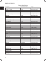
ENGINE SPECIFICATIONS AND DATA . . . . . . . . . . . . . . . . . . . . . . . . . . . . . . . . . . . . . . . . . . . . . . . . . . . . . . . . . . . . . 4
FASTENER SPECIFICATIONS . . . . . . . . . . . . . . . . . . . . . . . . . . . . . . . . . . . . . . . . . . . . . . . . . . . . . . . . . . . . . . . . . . . . . 6
BRIGGS & STRATTON NUMERICAL NUMBER SYSTEM . . . . . . . . . . . . . . . . . . . . . . . . . . . . . . . . . . . . . . . . . . . . . 7
MAINTENANCE SCHEDULE . . . . . . . . . . . . . . . . . . . . . . . . . . . . . . . . . . . . . . . . . . . . . . . . . . . . . . . . . . . . . . . . . . . . . . 8
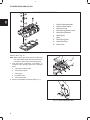
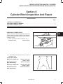
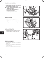
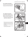
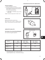
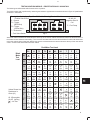
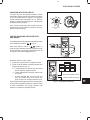
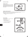
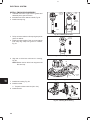
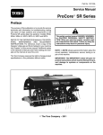
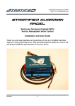
ENGINE IDENTIFICATION NUMBERS
The engine model and type number are located on the valve cover, Fig. 1. The serial number is stamped into the right
side of the cylinder block, behind the carburetor, Fig. 2.
MODEL AND
TYPE NO.
SERIAL NO.
Fig. 1 – Engine Model And Type Number
Fig. 2 – Engine Serial Number
SEPTEMBER, 2000
1
1
GENERAL INFORMATION
IN THE INTEREST OF SAFETY
THIS SAFETY ALERT SYMBOL INDICATES THAT THIS MESSAGE INVOLVES PERSONAL SAFETY.
SIGNAL WORDS DANGER, WARNING AND CAUTION INDICATE HAZARD DEGREE. DEATH,
PERSONAL INJURY AND/OR PROPERTY DAMAGE MAY OCCUR UNLESS INSTRUCTIONS ARE
FOLLOWED CAREFULLY.
WARNING: DO NOT
1. DO NOT run engine in an enclosed area. Exhaust
gases contain carbon monoxide, an odorless and
deadly poison.
2. DO NOT place hands or feet near moving or
rotating parts. Keep all guards in place.
3. DO NOT place hands or feet near electric cooling fan
(if equipped). Fan may start suddenly, depending on
coolant temperature.
4. DO NOT store, spill, or use gasoline near an open
flame, or devices such as a stove, furnace, or water
heater which use a pilot light or devices which can
create a spark.
5. DO NOT refuel indoors where area is not well
ventilated. Outdoor refueling is preferred.
6. DO NOT fill fuel tank while engine is running. Allow
engine to cool for 2 minutes before refueling. Store
fuel in approved, correct color safety containers.
7. DO NOT remove fuel tank cap while engine is
running.
8. DO NOT operate engine when smell of gasoline is
present or other explosive conditions exist.
9. DO NOT operate engine if gasoline is spilled.
Move machine away from the spill and avoid
creating any ignition until the gasoline has evaporated and dissipated.
10. DO NOT smoke when filling fuel tank.
11. DO NOT choke carburetor to stop engine. Whenever possible, gradually reduce engine speed before
stopping.
12. DO NOT run engine at excessive speeds. This may
result in injury.
13. DO NOT tamper with governor springs, governor
links or other parts which may increase the
governed engine speed.
14. DO NOT tamper with the engine speed selected by
the original equipment manufacturer.
15. DO NOT check for spark with spark plugs or spark
plug wires removed. Use an approved tester.
16. DO NOT crank engine with spark plug removed.
The fuel mixture exits the spark plug hole and can
be ignited outside the engine by the loose spark
plug or spark plug wire. If engine is flooded, place
throttle in “FAST’’ position and crank until engine
starts.
17. DO NOT operate engine with a damaged muffler or
without muffler. Inspect periodically and replace, if
necessary. If engine is equipped with muffler
deflector(s), inspect periodically and replace, if
necessary, with correct deflector(s).
18. DO NOT operate engine with an accumulation of
grass, leaves, dirt or other combustible material in
the muffler area.
19. DO NOT use starting fluid.
2
20. DO NOT use this engine on any forest covered,
brush covered, or grass covered unimproved land
unless a spark arrester is installed on the muffler.
The arrester must be maintained in effective
working order by the operator. In the State of
California the above is required by law (Section
4442 of the California Public Resources Code).
Other states may have similar laws. Federal laws
apply on federal lands.
21. DO NOT touch hot muffler(s) or cylinder(s) because
contact may cause burns.
22. DO NOT remove the radiator cap while the engine
is hot. To avoid scalding hot coolant or steam
blowing out of the radiator, use extreme care when
removing the radiator cap. If possible, wait for
engine to cool. If not possible, wrap a thick rag
around cap while removing. To release pressure,
slowly turn cap counter clockwise to the first stop.
When all pressure has been released, press down
on cap and continue turning.
23. DO NOT start or run engine with air cleaner or air
cleaner cover removed.
WARNING: DO
1. ALWAYS DO remove the wires from the spark
plugs when servicing the engine or equipment
TO PREVENT ACCIDENTAL STARTING. Disconnect the negative wire from the battery
terminal.
2. DO wear eye protection when operating or repairing
equipment.
3. DO keep governor parts free of grass and other
debris which can affect engine speed.
4. DO examine muffler(s) periodically to be sure it is
functioning effectively. A worn or leaking muffler(s)
should be repaired or replaced as necessary.
5. DO use fresh gasoline. Stale fuel can gum carburetor and cause leakage.
6. DO check fuel lines and fittings frequently for cracks
or leaks. Replace if necessary.
NOTE: Use Original Briggs & Stratton-Daihatsu
Service Replacement Parts when servicing your
engine. Authorized Briggs & Stratton-Daihatsu
Service Centers carry a stock of such parts. The use of
Briggs & Stratton-Daihatsu parts preserves the
original design of your engine. Imitation replacement
parts may not fit or function as original Briggs &
Stratton-Daihatsu parts and can expose the operator
to potential personal injury. Contact any Authorized
Briggs & Stratton-Daihatsu Service Center for Original
Briggs & Stratton-Daihatsu Replacement Parts.
1
GENERAL INFORMATION
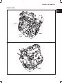
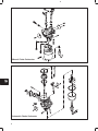
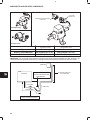
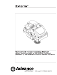
ENGINE VIEWS
BACK
FRONT
RIGHT
SIDE
LEFT
SIDE
3
1
GENERAL INFORMATION
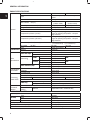
ENGINE SPECIFICATIONS
Model
Type
Valve mechanism
Bore x stroke
General
mm (in)
Piston displacement
Firing order
Compression ratio
cc (cu in)
Compression pressure (normal)
Cylinder Head
Valve
Specifications
Cylinder Block
& Camshaft
Connecting
Rod & Piston
Crankshaft &
Crankshaft
Bearing
430447
580447
Gasoline, 4-cycle, 3 cylinder, in-line, liquid
cooled
OHV, gear driven
68 x 64
72 x 78
(2.680 x 2.520)
(2.834 x 3.070)
697 (42.5)
952 (58.1)
1-2-3 (front, center, back)
8.6 : 1
14.0 kg/cm2 (200 psi) @ 400 rpm
Engine at operating temperature – all spark
plugs removed
11.0 kg/cm2 (155 psi) @ 400 rpm
Compression pressure (minimum)
Engine at operating temperature – all spark
plugs removed
Dimensions (L x W x H) mm (in)
435 x 395 x 492
435x395x502
(17.1x15.5x19.4) (17.1x15.5x19.7)
Dry weight
kg (lbs)
60 (132)
62 (137)
Type
Single piece casting
Material
Aluminum
Intake
30°
Valve seat angle
Exhaust
30°
Opens
10° BTDC
Intake
235°
Closes
45° ABDC
Valve timing
Opens
45° BBDC
Exhaust
235°
Closes
10° ATDC
Intake
mm (in) .18 (.007 in)
Valve clearance (cold)
Exhaust mm (in) .18 (.007 in)
Cylinder block
Mono-block, three cylinder, cast iron
Camshaft
Carbon steel
Connecting rod
Carbon steel
Piston Pin Bearing
Machined – Piston pin, press fit
Crankpin Bearing Material
Replaceable insert
Aluminum alloy
Piston
Heat resistant aluminum alloy
Compression ring
Two, chrome plated
Piston ring
Oil ring
One, combination type, chrome plated
Crankshaft
One piece cast iron
Crankshaft main
Material
Replaceable insert – Aluminum alloy
bearing
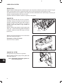
LUBRICATING SYSTEM
Lubricating Method
Type
Oil Pump
Drive
Oil Filter
Type
Oil Capacity
Oil Pump Relief Valve Opening Pressure
Lubrication Oil
4
Pressure lube
Trochoid
Gear drive
Full flow, paper
3.3 ltr (3.5 qt)
4.8 Bar (70 psi)
API SE class or higher
1
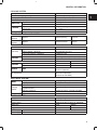
GENERAL INFORMATION
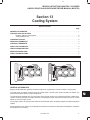
COOLING SYSTEM
Cooling Method
Coolant Capacity (engine only)
Cooling System Pressure
Pressure Cap Capacity
Type
Water Pump
Drive
Type
Thermostat
Specification
Liquid cooled, forced circulation
Approximately 1.8 ltr (1.9 qt)
1.0 – 0.75 Bar (15 – 11 psi)
0.9 Bar (13 psi).
Centrifugal
V-belt
Wax pellet with bypass
82° C (180° F)
Cooling Fan
V-belt
Drive
AIR INTAKE AND EXHAUST SYSTEM
Intake
Manifold
Exhaust
Manifold
Material
Natural aspirating
Aluminum
Material
Sideward exhaust
Cast Iron
FUEL SYSTEM
Fuel
Fuel Pump
p
Carburetor
Type
Delivery Output – Minimum
Fuel Pump Pressure – Maximum
Make
Type
Carburetor
Bore diameter
Venturi diameter
Governor
Type
Idle Speed RPM
Gasoline 85 octane minimum
Electric
350 cc/minute (12 fl. oz.)
0.25 Bar (3.5 psi)
Aisan Kogyo Co., Ltd {Nikki-optional}
Single barrel, Float Feed
Model 430447
Model 580447
24 mm
26 mm
17 mm
22 mm
Mechanical
Electronic {Optional}
1500 +/– 100 RPM
(Idle mixture adjustment
performed at 1200 RPM)
ELECTRICAL SYSTEM
Battery
Charging
System
Sys
e
Starter
Voltage
Capacity
Alternator
Regulator/rectifier
Alternator {Optional}
Type
12V (negative ground)
24 AH (28 AH cold)
28 Volt AC output – Minimum
14 Amp DC output with charge indicator circuit
40 Amp DC output – Internally regulated
12 Volt – Solenoid activated bendix drive
IGNITION SYSTEM
Voltage
Type
Ignition Timing
Spark Plug
Briggs & Stratton Daihatsu Part No. 491055
Spark Plug
Gap
Spark Plug
Thread
12 v (negative ground)
Transistorized Ignition
10° BTDC at idle/17.5 BTDC at 3600 RPM
N.G.K.
BKR4E
Champion
RC12YC
0.76 mm (.030”)
14 x 1.25 mm
5
1
GENERAL INFORMATION
Fastener Specifications
Description
Wrench/Socket Size
Torque
Alternator Adjust. Bracket.
12 mm
19.0 Nm (170 in. lbs.)
Alternator (to bracket)
12 mm
19.0 Nm (170 in. lbs.)
Alternator Bracket (to block)
12 mm
19.0 Nm (170 in. lbs.)
Camshaft Gear
17 mm
41.0 Nm (30 ft. lbs.)
Camshaft Retainer
10 mm
8.0 Nm (70 in. lbs.)
Carburetor (to manifold)
10 mm
8.0 Nm (70 in. lbs.)
Coil Bracket
12 mm
20.0 Nm (180 in. lbs.)
Conn. Rod Nuts
12 mm
36.0 Nm (320 in. lbs.)
Crankshaft Pulley
19 mm
88.0 Nm (65 ft. lbs.)
Cyl. Head Bolts (8mm dia.)
12 mm
34.0 Nm (25 ft. lbs.)
Cyl. Head Bolts (9mm dia.)
12 mm
35.0 Nm (26 ft. lbs.)
Exhaust Manifold
12 mm
19.0 Nm (170 in. lbs.)
Fan Pulley
10 mm
7.0 Nm (60 in. lbs.)
Flywheel
14 mm
47.0 Nm (35 ft. lbs.)
Governor Control Bracket
10 mm
8.0 Nm (70 in. lbs.)
Governor Nut
10 mm
10.0 Nm (90 in. lbs.)
Governor Paddle
Phillips
0.9 Nm (8 in. lbs.)
Idler Gear
12 mm
25.0 Nm (220 in. lbs.)
Intake Manifold
10 mm
7.0 Nm (60 in. lbs.)
Main Bearing Screws
14 mm
61.0 Nm (45 ft. lbs.)
Oil Drain Plug
14 mm
25.0 Nm (220 in. lbs.)
Oil Pan
10 mm
8.0 Nm (70 in. lbs.)
Oil Pressure Relief Valve
19 mm
34.0 Nm (25 ft. lbs.)
Oil Pump Gear
12 mm
19.0 Nm (170 in. lbs.)
Oil Pump Pickup
10 mm
8.0 Nm (70 in. lbs.)
Rear Seal Support
10 mm
6.0 Nm (50 in. lbs.)
Rocker Arm Assy.
12 mm Deep
19.0 Nm (170 in. lbs.)
Rocker Arm Adjustment
10 mm
11.0 Nm (95 in. lbs.)
Spark Plugs
16 mm Deep
21.0 Nm (170 in. lbs.)
Starter
14 mm
40.0 Nm (30 ft. lbs.)
Starter Bracket
14 mm
34.0 Nm (25 ft. lbs.)
Starter Solenoid
10 mm
8.0 Nm (70 in. lbs.)
Starter Thru Bolts
10 mm
8.0 Nm (70 in. lbs.)
Timing Gear Case
10 mm
8.0 Nm (70 in. lbs.)
Timing Gear Cover
(3 different lengths)
10 mm
8.0 Nm (70 in. lbs.)
Valve Cover
10 mm
6.0 Nm (50 in. lbs.)
Water Pump
12 mm
19.0 Nm (170 in. lbs.)
6
1
GENERAL INFORMATION
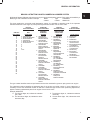
BRIGGS & STRATTON DAIHATSU NUMERICAL NUMBER SYSTEM
All Briggs & Stratton Daihatsu engines have a unique numerical designation system. Each engine is identified by a
Model, Type and Code/Serial number. Example:
Model
Type
Code/Serial
430447
0125 01
950521150
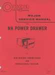
This chart explains the numerical model designation system. It is possible to determine most of the important
mechanical features of the engine by merely knowing the model number. Here is how it works.
CUBIC INCH
DISPLACEMENT
ă6
ă8
ă9
10
11
12
13
16
17
18
19
22
23
24
25
26
28
29
30
31
32
35
38
40
42
43
44
46
58
FIRST DIGIT
AFTER DISPLACEMENT
SECOND DIGIT
AFTER DISPLACEMENT
THIRD DIGIT
AFTER DISPLACEMENT
FOURTH DIGIT
AFTER DISPLACEMENT
BASIC
DESIGN SERIES
CRANKSHAFT,
CARBURETOR,
GOVERNOR
PTO BEARING,
REDUCTION GEAR,
AUXILIARY DRIVE,
LUBRICATION
TYPE OF STARTER
0 - Gas-Mechanical
1 - Natural Gas-Mechanical
2 - Diesel-Mechanical
3 - Gas-Electronic
4 - Natural Gas-Electronic
5 - Diesel-Electronic
6
7
8
9
A to Z
0 - Horizontal Shaft
Diesel Electronic or
Mechanical Governor
1 - Horizontal Shaft
VacuĆJet Carburetor
Pneumatic Governor
2 - Horizontal Shaft
PulsaĆJet Carburetor
Pneumatic or Mechanical
Governor
3 - Horizontal Shaft
FloĆJet Carburetor
Pneumatic Governor
4 - Horizontal Shaft
FloĆJet Carburetor
Electronic or
Mechanical Governor
5 - Vertical Shaft
VacuĆJet Carburetor
Pneumatic or Mechanical
Governor
6 - Vertical Shaft
7 - Vertical Shaft
FloĆJet Carburetor
Pneumatic or Mechanical
Governor
8 - Vertical Shaft
FloĆJet Carburetor
Mechanical Governor
9 - Vertical Shaft
PulsaĆJet Carburetor
Pneumatic or Mechanical
Governor
0 - Plain Bearing/DU
NonĆFlange Mount
1 - Plain Bearing
Flange Mounting
2 - Sleeve Bearing
Flange Mounting
Splash Lube
3 - Ball Bearing
Flange Mounting
Splash Lube
4 - Ball Bearing
Flange Mounting
Pressure Lubrication on
Horizontal Shaft
5 - Plain Bearing
Gear Reduction
(6 to 1) CW Rotation
Flange Mounting
6 - Plain Bearing
Gear Reduction
(6 to 1) CCW Rotation
7 - Plain Bearing
Pressure Lubrication on
Vertical Shaft
8 - Plain Bearing
Auxiliary Drive (PTO)
Perpendicular to Crankshaft
9 - Plain Bearing
Auxiliary Drive
Parallel to Crankshaft
0
1
2
3
-
45678-
Without Starter
Rope Starter
Rewind Starter
Electric Starter Only
120 Volt Gear Drive
Electric Starter/Generator
12 Volt Belt Drive
Electric Starter Only
12 Volt Gear Drive
Alternator Only
Electric Starter
12 Volt Gear Drive
With Alternator
Vertical Pull Starter or
Side Pull Starter
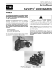
The type number identifies certain unique features such as the crankshaft or governor spring used on an engine.
The code/serial number identifies the assembly date of the engine and serial number. In some instances it is
necessary to know the code/serial number as well as the model and type number when performing adjustments,
repairs or ordering replacement parts for an engine. Here is how it works.
Example: 950521150
A. The first two digits, 95, indicate the calendar
year, 1995.
B. The second two digits, 05, indicate the calendar month, May.
C. The third two digits, 21, indicate the calendar
month day.
D. The last three digits, 150, indicate the serial
number.
7
1
GENERAL INFORMATION
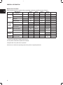
Maintenance Schedule
More frequent service is required when operating in adverse conditions (note 4 below).
ÎÎÎÎÎ
ÎÎÎÎÎ
Maintenance
Operation
Check oil level
Check for oil leaks
Lubrication
System
Change oil
Daily
Every
50 hours
Cooling
System
D1
D 2, 4
D1
D 2, 4
D
Change coolant
D
Service air cleaner
D1
D 2, 4
Check battery electrolyte
D 3, 4
D
D
D
Change spark plugs
Fuel System Change fuel filter
1 Perform first maintenance operation after 50 hours.
2 Then perform maintenance operation at this interval.
3 Replace after every 600 hours of operation.
4 Service more often when operating under heavy load or in high temperatures.
8
Yearly
D
Check valve clearance
Electrical
System
Every
600 hours
D
Check fan belt
Engine
Every
200 hours
D
Change oil filter
Check coolant
Every
100 hours
D
2
BRIGGS & STRATTON DAIHATSU 3 CYLINDER
LIQUID-COOLED GASOLINE ENGINE REPAIR MANUAL (MS-0750)
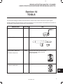
Section 2
Cylinder Head and Valves
Section Contents
Page
REMOVE CYLINDER HEAD . . . . . . . . . . . . . . . . . . . . . . . . . . . . . . . . . . . . . . . . . . . . . . . . . . . . . . . . . . . . . . . . . . . . . .
2
DISASSEMBLE CYLINDER HEAD . . . . . . . . . . . . . . . . . . . . . . . . . . . . . . . . . . . . . . . . . . . . . . . . . . . . . . . . . . . . . . . . . 4
INSPECT AND REPAIR
Cylinder Head . . . . . . . . . . . . . . . . . . . . . . . . . . . . . . . . . . . . . . . . . . . . . . . . . . . . . . . . . . . . . . . . . . . . . . . . . . . . 5
Valve Guides . . . . . . . . . . . . . . . . . . . . . . . . . . . . . . . . . . . . . . . . . . . . . . . . . . . . . . . . . . . . . . . . . . . . . . . . . . . . . 5
Valves . . . . . . . . . . . . . . . . . . . . . . . . . . . . . . . . . . . . . . . . . . . . . . . . . . . . . . . . . . . . . . . . . . . . . . . . . . . . . . . . . . 6
DISASSEMBLE ROCKER ARM SHAFT . . . . . . . . . . . . . . . . . . . . . . . . . . . . . . . . . . . . . . . . . . . . . . . . . . . . . . . . . . . . 7
ASSEMBLE ROCKER ARM SHAFT . . . . . . . . . . . . . . . . . . . . . . . . . . . . . . . . . . . . . . . . . . . . . . . . . . . . . . . . . . . . . . . . 8
ASSEMBLE CYLINDER HEAD . . . . . . . . . . . . . . . . . . . . . . . . . . . . . . . . . . . . . . . . . . . . . . . . . . . . . . . . . . . . . . . . . . . . 9
INSTALL CYLINDER HEAD . . . . . . . . . . . . . . . . . . . . . . . . . . . . . . . . . . . . . . . . . . . . . . . . . . . . . . . . . . . . . . . . . . . . . . 10
ADJUST VALVES . . . . . . . . . . . . . . . . . . . . . . . . . . . . . . . . . . . . . . . . . . . . . . . . . . . . . . . . . . . . . . . . . . . . . . . . . . . . . . . 13
Overhead Valve Train
SEPTEMBER, 2000
1
2
CYLINDER HEAD AND VALVES
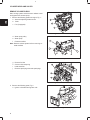
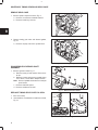
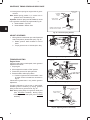
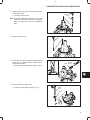
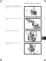
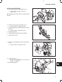
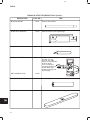
REMOVE CYLINDER HEAD
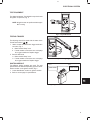
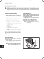
Drain cooling system and disconnect radiator hoses
and bypass hose at water pump.
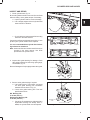
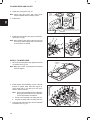
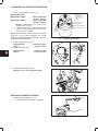
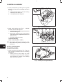
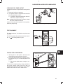
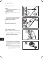
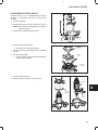
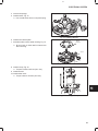
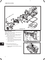
1. Remove the following parts from engine, Fig. 1:
C
a. Alternator adjusting bracket screw
b. V-belt
c.
A
Fan (if equipped)
B
Fig. 1 – Remove V-belt And Fan
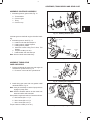
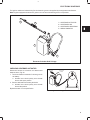
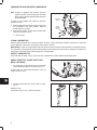
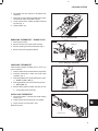
d. Water pump pulley
e. Water pump
f.
E
Exhaust manifold
Note: Remove exhaust system before removing exhaust manifold.
D
F
Fig. 2 – Remove Water Pump And Exhaust Manifold
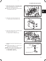
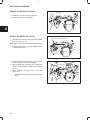
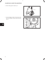
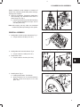
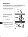
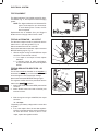
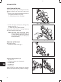
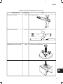
g. Remove fuel line
J
h. Governor link and spring
i.
Intake manifold
j.
Remove spark plug wires and spark plugs
H
G
I
Fig. 3 – Remove Intake Manifold
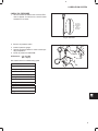
2. Remove the following parts, Fig. 4:
a. Ignition coil bracket and ignition coils.
Fig. 4 – Remove Ignition Coil Bracket
2
2
CYLINDER HEAD AND VALVES
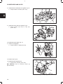
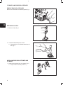
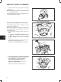
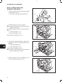
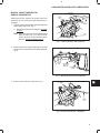
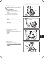
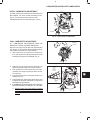
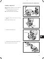
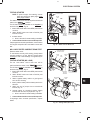
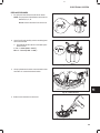
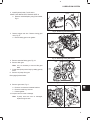
3. Remove valve cover, Fig. 5.
Fig. 5 – Remove Valve Cover
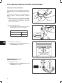
4. Set No. 1 piston at TDC:
REFERENCE
POINT
a. Rotate crankshaft pulley until timing mark on
pulley is aligned with reference point on timing
cover.
b. If intake and exhaust valves have clearance,
No. 1 piston is at TDC – compression stroke.
c.
If intake and exhaust valves do not have clearance, turn crankshaft pulley one complete revolution. Valves will then have clearance.
TIMING
MARK
Fig. 6 – Set Cylinder No. 1 at TDC
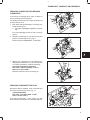
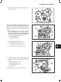
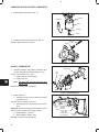
5. Remove rocker arm assembly and push rods,
Fig. 7.
VALVE
STEM
CAP
a. Remove valve stem caps.
Note: Mark push rods so that they may be reassembled in their original position.
Fig. 7 – Remove Rocker Arm Assembly And Push Rods
6. Remove cylinder head assembly, Fig. 8.
Note: Current style head bolts are 9 mm diameter.
Early style head bolts are 8 mm diameter.
Torque specifications are different.
6
10
a. Loosen cylinder head bolts in the order
shown.
2
4
13
8
11
7
12
3
14
9
5
1
Fig. 8 – Loosen Cylinder Head Bolts
3
2
CYLINDER HEAD AND VALVES
3
4
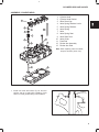
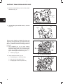
DISASSEMBLE CYLINDER HEAD
5
6
9
10
1
8
7
2
1.
2.
3.
4.
5.
6.
7.
8.
9.
10.
Cylinder Head Assembly
Cylinder Head Gasket
Valve Stem Cap
Valve Spring Retainer Locks
Valve Spring Retainer
Valve Spring
Valve
Valve Spring Seat
Valve Stem Seal
Valve Guide
Fig. 9 – Cylinder Head Components
Remove valves, Fig. 10.
Note: Place a shop rag or short section of rubber fuel
line under valves inside combustion chamber to
hold valve in place while compressing spring.
7. Use valve spring compressor, Tool #19417, to
compress valve springs. Remove the following
parts:
a. Valve spring retainer locks
b. Valve spring retainer
c.
Valve spring
d. IN and EX valve
Fig. 10 – Remove Valves
e. Valve spring seats
8. Remove and discard valve stem seals, Fig. 11.
Fig. 11 – Remove Valve Stem Seal
4
2
CYLINDER HEAD AND VALVES
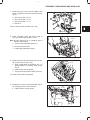
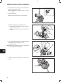
INSPECT AND REPAIR
STRAIGHT
EDGE
1. Check cylinder head, Fig. 12.
Be sure all gasket material is removed from surfaces
before checking. Use a gasket scraper if necessary.
a. Inspect cylinder head for cracks or damage.
b. Use a straight edge and check cylinder head
lower surface for distortion.
Fig. 12 – Check Cylinder Head For Distortion
c.
Check intake and exhaust manifold mounting
surfaces in the same manner.
If mounting surfaces are distorted more than 0.1 mm
(0.004 in), the cylinder head must be replaced.
It is not recommended that cylinder head mounting surfaces be resurfaced.
Note: Intake manifold and exhaust manifold may be
checked in the same manner. Use same
specifications as cylinder head.
Fig. 13 – Check Cylinder Head For Distortion
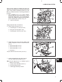
2. Inspect valve guide bushing for damage. Check
valve guide bushings for wear using reject gauge,
Tool #19382, Fig. 14.
Remove if damaged or if reject gauge enters valve guide.
REJECT GAGE
Fig. 14 – Check Valve Guide Bushing
3. Remove valve guide bushing if required.
a. Use bushing driver, Tool #19367, and press
out valve guide bushing from combustion
chamber side as shown in Fig. 15.
b. Check valve guide bushing OD. Then see
specifications below.
Std. Bushing OD:
11.05 mm (.435 in.)
Replacement Bushing OD:
11.08 mm (.4362 in.)
c. If bushing OD measurement indicates that a
replacement bushing has already been installed, the cylinder head must be replaced.
PRESSING OUT
GUIDE
Fig. 15 – Remove Valve Guide Bushing
5
2
CYLINDER HEAD AND VALVES
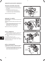
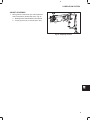
4. Using bushing driver, Tool #19416, press in new
valve guide bushing until tool bottoms on cylinder
head, Fig. 16.
Fig. 16 – Installing Valve Guide Bushing
5. Valve faces may be resurfaced to 30°. See Fig. 17
for dimensions for valves. Lap valves and seats
with valve lapping tool, #19258 and valve lapping
compound, tool #94150.
1/32”
MINIMUM
1.2 MM TO 1.6 MM
(3/64” TO 1/16”)
SEATING AREA CENTERED
ON VALVE FACE
Fig. 17 – Valve Dimensions
6. Valve seats may be reconditioned using valve seat
cutter tool #19446.
Note: Check valve guide bushings first. If valve guides
are worn, they must be replaced before refacing
valve seats
If valve seat is wider than dimension shown in Fig. 18, a
narrowing cutter should be used to ensure that contact
area of valve seat is centered on face of valve.
a. Use a 45° cutter to narrow seat from bottom
and a 15° cutter to narrow seat from top,
Fig. 18.
Note: If valve seat is loose or cracked, replace cylinder
head.
1.2 MM TO 1.6 MM
(3/64” TO 1/16”)
30°
ÉÉÉ
ÉÉÉ
ÉÉÉ
ÉÉÉ
45° CUTTER
VALVE SEAT DIMENSIONS
15° CUTTER
ÉÉ
ÉÉ
ÉÉ
ÉÉ
Fig. 18 – Valve Seat Dimensions
7. Measure valve stem diameter at specified distance from end of valve, as shown in Fig. 19.
Replace IN if less than 5.952 mm (0.2343 in).
35 MM
(1.38”)
Replace EX if less than 5.948 mm (0.2342 in).
Fig. 19 – Measure Valve Stem Diameter
6
2
CYLINDER HEAD AND VALVES
8. Inspect valve stem cap for wear, Fig. 20.
Replace if cap is worn recessed.
Fig. 20 – Check Valve Stem Cap
9. Check valve springs for squareness and free
length, Fig. 21.
Replace if out of square more than 1.0 mm
(.040 in).
Replace if free length is less than 29.2 mm
(1.150 in).
Fig. 21 – Check Valve Springs
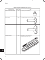
DISASSEMBLE ROCKER ARM SHAFT
Remove snap rings from ends of rocker arm shaft. Remove set screw from center rocker arm support. Disassemble rocker
arm assembly. Note position of all components, Fig. 22.
SET
SCREW
(1)
SPRING
(2)
ROCKER
ARM
(6)
ROCKER
ARM SUPPORT
(3)
THRUST
WASHER
(3)
SNAP
RING
(2)
ROCKER
ARM
SHAFT
Fig. 22 – Rocker Arm Components
7
2
CYLINDER HEAD AND VALVES
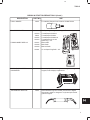
10. Check rocker arms and shaft
a. Check rocker arm-bearing.
Replace if greater than 10.03 mm (0.395”).
b. Check rocker arm shaft.
Replace if less than 9.957 mm (0.392”).
c. Check rocker arm studs for stripped threads
and replace if required.
Fig. 23 – Checking Rocker Arm And Shaft
ASSEMBLE ROCKER ARM SHAFT
1. Oil all components before assembling. Small grooves in rocker shaft next to oil holes must face down. Assemble
rocker arm components, noting order of assembly as shown in Fig. 24. Note position of three thrust washers.
Install set screw in center rocker arm shaft support.
SET
SCREW
(1)
SPRING
(2)
ROCKER
ARM
SHAFT
THRUST
WASHER
(3)
OIL
GROOVES
DOWN
ROCKER
ARM SUPPORT
(3)
Fig. 24 – Rocker Arm Components
8
ROCKER
ARM
(6)
SNAP
RING
(2)
2
CYLINDER HEAD AND VALVES
ASSEMBLE CYLINDER HEAD
12
3
11
4
5
6
13
9
1
10
8
1.
2.
3.
4.
5.
6.
7.
8.
9.
10.
11.
12.
13.
Cylinder Head
Cylinder Head Gasket
Valve Stem Cap
Valve Spring Retainer Locks
Valve Spring Retainer
Valve Spring
Valve
Valve Spring Seat
Valve Stem Seal
Valve Guide
Push Rod
Rocker Arm Assembly
Rocker Arm Stud
Note: When replacing rocker arm studs,
torque to 20.0 Nm (180 in. lbs.)
7
2
Fig. 25 – Cylinder Head Components
1. Install new valve stem seals, Fig. 26. Oil inner
surface and lip of seal before installing. Press
seal on to valve guide bushing until it bottoms.
VALVE STEM
SEAL
(CUTAWAY VIEW)
Fig. 26 – Install Valve Stem Seals
9
2
CYLINDER HEAD AND VALVES
2. Install valve spring seats, Fig. 27.
Note: Lightly coat valve stems with Valve Guide
Lubricant #93963 before installing valves.
3. Install valves.
VALVE
SPRING
SEATS
Fig. 27 – Install Valve Spring Seats And Valves
4. Install valve springs with valve spring compressor,
Tool #19417, Fig. 28.
Note: After installing valve spring retainer locks, tap
valve spring retainer lightly with a soft hammer
to ensure locks are seated.
Fig. 28 – Install Valve Springs
INSTALL CYLINDER HEAD
ALIGNMENT
DOWELS
1. Place cylinder head gasket over alignment dowels
on cylinder block, Fig. 29.
Note: Make sure coolant, oil passages and head bolt
holes are aligned.
Fig. 29 – Install Cylinder Head Gasket
2. Install cylinder head assembly, Fig. 30. Lubricate
threads of cylinder head bolts with engine oil.
Torque head bolts in 13.0 Nm (10 ft. lbs.) increments in sequence shown.
Note: Current style head bolts are 9 mm diameter.
Early style head bolts are 8 mm diameter.
Torque specifications are different.
a. Torque 9 mm head bolts to 35.0 Nm (26 ft. lb.).
RECESSED
END UP
8
6
14
11
2
9
4
10
3
12
1
b. Torque 8 mm head bolts to 34.0 Nm (25 ft. lb.).
3. Lubricate push rods with engine oil then install with
recessed end up, Fig. 30.
7
5
13
Fig. 30 – Install Cylinder Head Assembly
10
2
CYLINDER HEAD AND VALVES
4. Install valve stem caps on valve stems. Install
rocker arm assembly, Fig. 31. Install washers and
torque nuts to 19.0 Nm (170 in. lbs.).
Note: Make sure rocker adjustment studs are seated
in recessed end of push rods.
Fig. 31 – Install Rocker Arm Assembly
5. Install ignition coil bracket and ignition coils.
a. Torque screws to 20.3 Nm (180 in. lbs.)
Fig. 32 – Install Ignition Coil Bracket And Ignition Coils
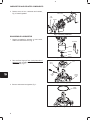
6. Install intake manifold with new gasket. Install
governor link and spring, Fig. 34.
GOVERNOR
LINK AND
SPRING
a. Torque screws to 7.0 Nm (60 in. lbs).
INTAKE
MANIFOLD
Fig. 33 – Install Intake Manifold And Governor Link
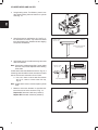
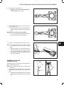
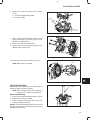
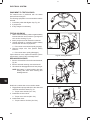
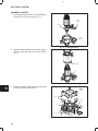
7. Insert governor spring into original hole in governor lever.
Note: Normal spring position is in center hole in
governor lever, all models, Fig. 34.
Important: Governor spring must be installed in correct
hole in governor control lever by engine model, Fig. 34.
a. Model 430400 – Top Hole
b. Model 580400 – Bottom Hole
GOVERNOR
CONTROL
LEVER
MODEL 580400
BOTTOM HOLE
NORMAL SPRING POSITION
CENTER HOLE ALL MODELS
MODEL 430400
TOP HOLE
GOVERNOR
SPRING
GOVERNOR
LEVER
Fig. 34 – Governor Spring Position
11
2
CYLINDER HEAD AND VALVES
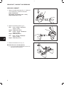
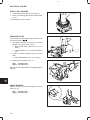
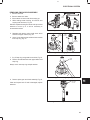
8. Install exhaust manifold with new gasket, Fig. 35.
a. Torque screws to 19.0 Nm (170 in. lbs.).
Fig. 35 – Install Exhaust Manifold
9. Install water pump with new gasket, Fig. 36.
a. Torque screws and nuts to 19.0 Nm
(170 in. lbs.).
Fig. 36 – Install Water Pump
10. Install water pump pulley, Fig. 37.
11. Install fan (if equipped).
a. Torque screws to 7.0 Nm (60 in. lbs).
Fig. 37 – Install Water Pump Pulley And Fan
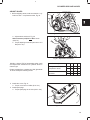
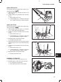
12. Install V-belt, Fig. 38.
13. Install alternator adjusting bolt.
a. Torque bolt to 19.0 Nm (170 in. lbs.).
Belt deflection limit is 10.0-12.0 mm/10 kg
(3/8-1/2 in/22 lb).
Fig. 38 – Adjusting V-belt
12
2
CYLINDER HEAD AND VALVES
ADJUST VALVES
REFERENCE POINT
1. Before adjusting valves, make sure that No. 1 cylinder is at TDC – compression stroke, Fig. 39.
Fig. 39 – Set Cylinder No. 1 at TDC
a. Adjust valves and check, Fig. 40.
Valve Clearance (cold) IN and EX 0.18 mm
(0.007 in.)
b. Torque adjusting screws and jam nuts to 11.0
Nm (95 in. lbs.).
Fig. 40 – Adjust Valve Clearances
With No. 1 piston at TDC of compression stroke, check
and adjust valve clearances for cylinders shown in
chart at right.
Rotate crankshaft one complete turn (360°) clockwise
to check and adjust remaining valves.
1
Piston Position Cylinder
No. 1 piston at TDC, of
compression stroke
Rotate Crankshaft 360
360°
clockwise
IN
l
EX
l
IN
EX
2
3
l
l
l
l
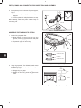
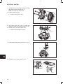
2. Install valve cover, Fig. 41.
a. Torque cover nuts to 6.0 Nm (50 in. lbs.).
3. Install spark plugs.
a. Torque spark plugs to 18.0 Nm (160 in. lbs.).
Fig. 41 – Install Valve Cover
13
3
BRIGGS & STRATTON DAIHATSU 3 CYLINDER
LIQUID-COOLED GASOLINE ENGINE REPAIR MANUAL (MS-0750)
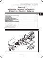
Section 3
Mechanical Governor/Timing Gears
& Gear Case Electronic Governor
Section Contents
Page
REMOVE TIMING GEAR COVER AND GEARS . . . . . . . . . . . . . . . . . . . . . . . . . . . . . . . . . . . . . . . . . . . . . . . . . . . . . . 2
CHECKING GEARS . . . . . . . . . . . . . . . . . . . . . . . . . . . . . . . . . . . . . . . . . . . . . . . . . . . . . . . . . . . . . . . . . . . . . . . . . . . . . . 3
REMOVE GEAR CASE . . . . . . . . . . . . . . . . . . . . . . . . . . . . . . . . . . . . . . . . . . . . . . . . . . . . . . . . . . . . . . . . . . . . . . . . . . . 4
DISASSEMBLE GOVERNOR SHAFT . . . . . . . . . . . . . . . . . . . . . . . . . . . . . . . . . . . . . . . . . . . . . . . . . . . . . . . . . . . . . . . 4
REPLACE TIMING GEAR COVER OIL SEAL . . . . . . . . . . . . . . . . . . . . . . . . . . . . . . . . . . . . . . . . . . . . . . . . . . . . . . . 4
ASSEMBLE GOVERNOR . . . . . . . . . . . . . . . . . . . . . . . . . . . . . . . . . . . . . . . . . . . . . . . . . . . . . . . . . . . . . . . . . . . . . . . . . 5
ASSEMBLE TIMING GEAR CASE AND GEARS . . . . . . . . . . . . . . . . . . . . . . . . . . . . . . . . . . . . . . . . . . . . . . . . . . . . . 5
ADJUST GOVERNOR . . . . . . . . . . . . . . . . . . . . . . . . . . . . . . . . . . . . . . . . . . . . . . . . . . . . . . . . . . . . . . . . . . . . . . . . . . . . 8
TROUBLESHOOTING . . . . . . . . . . . . . . . . . . . . . . . . . . . . . . . . . . . . . . . . . . . . . . . . . . . . . . . . . . . . . . . . . . . . . . . . . . . . 8
ELECTRONIC GOVERNOR . . . . . . . . . . . . . . . . . . . . . . . . . . . . . . . . . . . . . . . . . . . . . . . . . . . . . . . . . . . . . . . . . . . . . . . 9
CHECKING GOVERNOR ACTUATOR . . . . . . . . . . . . . . . . . . . . . . . . . . . . . . . . . . . . . . . . . . . . . . . . . . . . . . . . . . . . . . 9
REMOVE GOVERNOR ACTUATOR . . . . . . . . . . . . . . . . . . . . . . . . . . . . . . . . . . . . . . . . . . . . . . . . . . . . . . . . . . . . . . . 10
INSTALL GOVERNOR ACTUATOR . . . . . . . . . . . . . . . . . . . . . . . . . . . . . . . . . . . . . . . . . . . . . . . . . . . . . . . . . . . . . . . 10
SEPTEMBER, 2000
1
3
GOVERNOR, TIMING GEARS AND GEAR CASE
REMOVING TIMING GEAR
COVER AND GEARS
Make sure that #1 cylinder is at TDC, compression
stroke. See Section 2.
Remove V-belt and fan (if equipped). Drain oil from
engine.
Note: Before removing governor spring, note hole position of governor spring in governor lever.
1. Remove the following parts.
A
C
a. Remove governor link spring, and governor
link from carburetor.
B
b. Remove governor spring from governor lever.
c.
Loosen nut and remove governor lever from
governor shaft, Fig. 1.
Fig. 1 – Remove Governor Lever
2. Remove oil pan screws and nuts, Fig. 2.
a. Remove oil pan and discard gasket.
OIL PICK-UP
TUBE
b. Remove oil pick-up tube and strainer. Discard
gasket.
Fig. 2 – Removing Oil Pan
3. Remove bell housing adapter screw if equipped.
and install flywheel holder, Tool #19418.
FLYWHEEL
HOLDER
LEAVE TOOL INSTALLED.
a. Remove crankshaft pulley using Tool
#19420, Fig. 3.
Fig. 3 – Removing Crankshaft Pulley
4. Remove trigger and wire. Remove timing gear
cover, Fig. 4.
a. Discard timing gear cover gasket.
TRIGGER
Fig. 4 – Removing Timing Gear Cover
2
3
GOVERNOR, TIMING GEARS AND GEAR CASE
5. Remove governor gear, Fig. 5.
a. Governor cup
GOVERNOR
GEAR
C
B
b. E-ring
c.
Governor gear
d. Thrust washer
6. Remove oil pump drive gear.
A
D
OIL
PUMP
GEAR
Check governor gear and oil pump drive gear for
damaged teeth.
Fig. 5 – Removing Governor Gear
CHECKING GEARS
Inspect gear teeth for wear or damage. CHECK
GEARS IN SEQUENCE SHOWN.
1. Check gear back lash between idler gear and
crankshaft gear using dial indicator as shown in
Fig. 6.
IDLER
GEAR
CRANKSHAFT
GEAR
a. Set tip of indicator on gear tooth, then rock
idler gear back and forth noting indicator
reading.
Note: Crankshaft must not turn while checking.
Fig. 6 – Checking Idler Gear Backlash
2. If back lash exceeds 0.2 mm (.008”) check idler
gear bearing and shaft for wear, Fig. 7.
Reject Dimension: Idler Gear ID –
34.17 mm (1.345”)
Idler Gear Shaft OD –
33.91 mm (1.335”)
a. If idler gear bearing and shaft are within specification, replace with new idler gear and recheck.
IDLER
GEAR
IDLER
GEAR
SHAFT
Fig. 7 – Checking Idler Gear And Shaft
b. If backlash exceeds 0.2 mm (.008”) with NEW
idler gear, crankshaft gear is worn.
Note: If crankshaft gear is worn the crankshaft must
be replaced.
3. Hold idler gear as shown and check gear backlash
between camshaft timing gear and idler gear using
dial indicator, Fig. 8.
CAMSHAFT
TIMING
GEAR
Camshaft timing gear back lash must not exceed
0.2 mm (.008”).
Note: Idler gear must not turn while checking.
If gears are worn it is recommended that they be
replaced as a set.
IDLER
GEAR
Fig. 8 – Checking Camshaft Timing Gear Backlash
3
3
GOVERNOR, TIMING GEARS AND GEAR CASE
REMOVE GEAR CASE
A
1. Remove parts in sequence shown, Fig. 9.
a. Remove 3 screws and camshaft retainer.
b. Remove remaining 5 screws.
B
Fig. 9 – Removing Timing Gear Case
2. Remove timing gear case and discard gasket,
Fig. 10.
a. Remove oil pump rotor from cylinder block.
Fig. 10 – Removing Timing Gear Case
DISASSEMBLE GOVERNOR SHAFT
ASSEMBLY
B
C
1. Remove governor shaft, Fig. 11.
a. Remove cotter pin and washer. Discard cotter pin.
b. Remove screws and governor paddle using
TorxR driver, Tool # 19445. Discard screws.
Note: Governor paddle screws are TorxR tamper
proof screws.
c. Remove shaft and spacer.
d. Remove and discard oil seal.
D
C
WASHER
Fig. 11 – Remove Governor Shaft
REPLACE TIMING GEAR COVER OIL SEAL
1. Drive out oil seal.
2. Use seal driver, Tool #19423 to install new oil seal,
Fig. 12.
Fig. 12 – Replacing Oil Seal
4
A
3
GOVERNOR, TIMING GEARS AND GEAR CASE
ASSEMBLE GOVERNOR ASSEMBLY
1. Assemble governor gear to shaft, Fig. 13.
a. Thrust washer
b. Governor gear
c.
B
C
E-ring
d. Governor cup
D
A
Fig. 13 – Installing Governor Gear
Lubricate governor shaft with engine oil before installing.
2. Assemble governor shaft, Fig. 14.
PADDLE
SPACER
a.
b.
c.
d.
Install new oil seal with seal lips in.
Install governor shaft and spacer.
Install governor paddle.
Install new screws using TorxR driver, Tool
#19445.
e. Torque to 0.9 Nm (8 in. lbs.).
f. Install washer and new cotter pin
OIL
SEAL
GOVERNOR
SHAFT
COTTER
PIN
Note: Governor shaft must rotate freely.
WASHER
Fig. 14 – Installing Governor Shaft
ASSEMBLE TIMING GEAR
CASE AND GEARS
1. Clean and lubricate oil pump rotor with engine oil
and install in cylinder block, Fig. 15.
ID MARK
a. ID mark on rotor must face cylinder block.
OIL PUMP
ROTOR
Fig. 15 – Installing Oil Pump Rotor
2. Install timing gear case with new gasket. Install
camshaft retainer, Fig. 16.
B
Note: It may be necessary to rotate oil pump drive to
engage oil pump rotors.
Note: Position camshaft retainer so that center hole
does not interfere with camshaft.
Note position, length and number of screws as shown.
a. M6 x 28 mm (M6 x 1.1”): 4
C
RETAINER
A
b. M6 x 18 mm (M6 x 0.7”): 3
c.
M6 x 16 mm (M6 x 0.6”): 1
Torque screws to 8.0 Nm (70 in. lbs.).
Fig. 16 – Installing Timing Gear Case
5
3
GOVERNOR, TIMING GEARS AND GEAR CASE
3. Make sure crankshaft key is at 12 o’clock position
as shown in Fig. 17.
CRANKSHAFT
KEY
12 O’CLOCK
Fig. 17 – Crankshaft Position
4. Assemble idler gear shaft with arrow up, as shown
in Fig. 18.
ARROW
UP
Fig. 18 – Installing Idler Gear Shaft
Engine models 430000 and 580000 after date code
990111007 are equipped with right angle helical timing
gears. Timing marks are identified by letters (A, AA, B,
BB, etc. ), instead of numbers. The timing procedure is
the same.
5. With crankshaft key at 12 o’clock position,
assemble idler gear so that timing mark 11 (AA) is
aligned with timing mark 1 (A) on crankshaft gear,
timing mark 22 (BB) is aligned with timing mark 2
(B) on camshaft gear as shown in Fig. 19.
22
2
11
A
1
a. Install oil pump gear.
Fig. 19 – Aligning Timing Marks
6. Torque screws as shown, Fig. 20.
a. Camshaft gear: 41.0 Nm (30 ft. lbs.)
A
B
b. Idler gear: 25.0 Nm (220 in. lbs.)
c.
Oil pump gear: 19.0 Nm (170 in. lbs.)
C
Fig. 20 – Torque Screws
6
3
GOVERNOR, TIMING GEARS AND GEAR CASE
7. Install timing gear cover with new gasket. Note
position, length and number of screws as shown,
Fig. 21.
B
D
C
C
a. M6 x 65 mm (M6 x 2.5”): 2
b. M6 x 55 mm (M6 x 2.1”): 3
c.
A
D
M6 x 30 mm (M6 x 1.1”): 7
d. M6 Nut: 2
C
Torque screws and nuts to 8.0Nm (70 in. lbs.).
C
B
B
Fig. 21 – Installing Timing Gear Cover
8. Install crankshaft pulley with timing mark at
12 o’clock position (#1 cylinder), Fig. 22.
TRIGGER
Note: Be sure alignment pin in crankshaft gear is
seated in hole in pulley.
a. Torque screw to 88.0 Nm (65 ft. lbs.).
b. Remove flywheel holder.
c.
Install trigger assembly and wire.
Fig. 22 – Installing Crankshaft Pulley
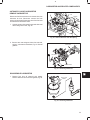
9. Install oil pick-up tube and strainer with new gasket. Torque to 8.0 Nm (70 in. lbs.).
SEALANT
a. Apply a small bead of PermatexR No. 2 or
similar sealant to crankcase areas shown,
Fig. 23.
b. Install oil pan with new gasket.
c.
Torque screws and nuts to 8.0 Nm (70 in. lbs.).
10. Install V-belt and fan (if equipped).
Fig. 23 – Installing Oil Pan
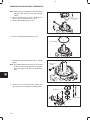
11. Install governor lever on to governor shaft, Fig. 24.
Do not tighten governor nut at this time.
GOVERNOR
LINK &
SPRING
a. Install governor link with spring.
GOVERNOR
LEVER
Fig. 24 – Installing Governor Lever
7
3
GOVERNOR, TIMING GEARS AND GEAR CASE
12. Insert governor spring into original hole in governor lever.
Note: Normal spring position is in center hole in
governor lever, all models, Fig. 25.
Important: Governor spring must be installed in correct
hole in governor control lever by engine model, Fig. 25.
a. Model 430400 – Top Hole
b. Model 580400 – Bottom Hole
MODEL 430400
TOP HOLE
GOVERNOR
CONTROL
LEVER
MODEL 580400
BOTTOM HOLE
GOVERNOR
SPRING
NORMAL SPRING POSITION
CENTER HOLE ALL MODELS
GOVERNOR
LEVER
Fig. 25 – Governor Spring Position
ADJUST GOVERNOR
1. Move governor control lever up to end of travel and
hold in this position (throttle wide open), Fig. 26.
a. Rotate governor shaft clockwise to end of
travel.
b. Torque governor nut to 10.0 Nm (90 in. lbs.).
GOVERNOR
CONTROL
LEVER
NUT
GOVERNOR
SHAFT
Fig. 26 – Adjusting Governor
TROUBLESHOOTING
Engine Hunts
1 MM
WIDE OPEN
THROTTLE
If engine hunts at top no load speed, check governor
adjustment as follows:
1. Stop engine.
2. Move equipment control to “Fast” position.
3. Disconnect governor link spring and link.
4. Rotate throttle to wide open position.
a. Position of governor link must be within 1 mm
of center of hole in throttle lever as shown in
Fig. 27.
If dimension is greater than 1 mm, perform governor
adjustment.
Fig. 27 – Checking Adjustment
If engine continues to hunt at top no load speed,
decrease governor sensitivity by moving governor
spring to next hole on governor lever, Fig. 28.
Note: Moving spring away from governor shaft pivot
point decreases sensitivity. Moving spring
towards governor shaft pivot point increases
sensitivity.
NORMAL SPRING POSITION
CENTER HOLE
MOVE GOVERNOR
SPRING 1 HOLE
LESS
SENSITIVE
MORE
SENSITIVE
Fig. 28 – Adjusting Governor Sensitivity
8
3
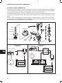
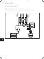
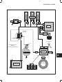
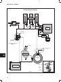
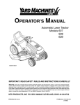
ELECTRONIC GOVERNOR
The ignition module and related wiring for the electronic governor is supplied by the equipment manufacturer.
Note: Engines equipped with electronic governor do not have mechanical governor components.
2
1 – GOVERNOR ACTUATOR
2 – GOVERNOR LINK
3 – GOVERNOR LINK SPRING
4 – WIRING HARNESS
3
1
4
Governor Actuator And Linkage
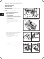
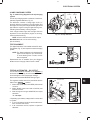
CHECKING GOVERNOR ACTUATOR
Disconnect harness at connector and attach tests
leads as shown, Fig. 29.
1. Touch test leads to terminals of a known good 12
volt battery.
WIDE OPEN
THROTTLE
ACTUATOR
LEVER
a. Actuator lever should quickly move throttle
lever to wide open position.
2. Remove test leads from battery terminals:
b. Actuator lever should quickly move throttle
lever to idle position.
Replace actuator if not to specification.
Fig. 29 – Checking Governor Actuator
9
3
ELECTRONIC GOVERNOR
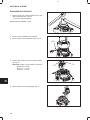
REMOVE GOVERNOR ACTUATOR
GOVERNOR LINK
AND SPRING
1. Disconnect governor link spring and link.
2. Remove two screws and actuator.
SCREWS
Fig. 30 – Removing Governor Actuator
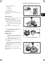
INSTALL GOVERNOR ACTUATOR
OPEN ENDS TOWARD CYLINDER HEAD
1. Assemble governor link spring and link to actuator
lever as shown, Fig. 31.
Note: Open ends of spring must face cylinder head.
2. Assemble actuator to mounting bracket loosely.
Do not tighten screws.
Fig. 31 – Install Actuator
3. Rotate throttle lever clockwise to end of travel
(throttle closed) and hold in this position.
GOVERNOR LINK
4. Slide actuator until governor link is positioned
slightly to rear of hole in throttle lever bushing,
Fig. 32.
5. Torque actuator mounting screws to 8.0 Nm
(70 in. lbs.).
a. Assemble governor link and spring to throttle
lever.
THROTTLE LEVER
BUSHING
Fig. 32 – Adjust Actuator
10
4
BRIGGS & STRATTON DAIHATSU 3 CYLINDER
LIQUID-COOLED GASOLINE ENGINE REPAIR MANUAL (MS-0750)
Section 4
Flywheel And Rear Seal Retainer
Section Contents
Page
REMOVING OIL PAN AND FLYWHEEL . . . . . . . . . . . . . . . . . . . . . . . . . . . . . . . . . . . . . . . . . . . . . . . . . . . . . . . . . . . . . 1
REMOVING REAR SEAL RETAINER . . . . . . . . . . . . . . . . . . . . . . . . . . . . . . . . . . . . . . . . . . . . . . . . . . . . . . . . . . . . . . . 2
REPLACING OIL SEAL . . . . . . . . . . . . . . . . . . . . . . . . . . . . . . . . . . . . . . . . . . . . . . . . . . . . . . . . . . . . . . . . . . . . . . . . . . . 2
INSTALLING REAR SEAL RETAINER AND FLYWHEEL . . . . . . . . . . . . . . . . . . . . . . . . . . . . . . . . . . . . . . . . . . . . . . 2
INSTALL OIL PAN . . . . . . . . . . . . . . . . . . . . . . . . . . . . . . . . . . . . . . . . . . . . . . . . . . . . . . . . . . . . . . . . . . . . . . . . . . . . . . . 3
REMOVING PAN AND FLYWHEEL
Drain oil from engine.
1. Remove oil pan screws and nuts. Remove oil pan
and discard gasket, Fig. 1.
Fig. 1 – Removing Oil Pan
2. Install flywheel holder, Tool #19418
a. Remove flywheel screws and flywheel, Fig. 2.
FLYWHEEL
HOLDER
Inspect flywheel for cracks or damage. Inspect flywheel ring gear for worn, chipped or cracked teeth.
If ring gear is worn or damaged the flywheel must be
replaced.
Fig. 2 – Removing Flywheel
SEPTEMBER, 2000
1
4
FLYWHEEL AND REAR SEAL RETAINER
REMOVE REAR SEAL RETAINER
Remove rear seal retainer and discard gasket, Fig. 3.
Fig. 3 – Removing Seal Retainer
REPLACING OIL SEAL
1. Remove oil seal, Fig. 4.
Fig. 4 – Removing Oil Seal
2. Lubricate outside diameter of oil seal.
a. Using seal driver, Tool #19424 install new oil
seal, Fig. 5.
Fig. 5 – Installing Oil Seal
INSTALLING REAR SEAL RETAINER AND
FLYWHEEL
1. Install rear seal retainer with new gasket, Fig. 6.
a. Torque screws to 6.0 Nm (50 in. lbs.).
RETAINER
GASKET
Fig. 6 – Installing Seal Retainer
2
4
FLYWHEEL AND REAR SEAL RETAINER
2. Install flywheel, Fig. 7.
Note: Apply PermatexR No. 2 or similar sealant to
flywheel screws.
a. Torque flywheel screws to 47.0 Nm
(35 ft. lbs.).
Remove flywheel holder.
Fig. 7 – Installing Flywheel
INSTALL OIL PAN
SEALANT
1. Install oil pan with new gasket, Fig. 8.
a. Apply a small bead of PermatexR No. 2 or
similar sealant to crankcase areas shown.
b. Torque screws
(70 in. lbs.).
and
nuts
to
8.0
Nm
Fig. 8 – Installing Oil Pan
3
5
BRIGGS & STRATTON DAIHATSU 3 CYLINDER
LIQUID-COOLED GASOLINE ENGINE REPAIR MANUAL (MS-0750)
Section 5
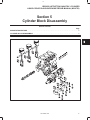
Cylinder Block Disassembly
Section Contents
Page
ENGINE STAND FIXTURE . . . . . . . . . . . . . . . . . . . . . . . . . . . . . . . . . . . . . . . . . . . . . . . . . . . . . . . . . . . . . . . . . . . . . . .
2
CYLINDER BLOCK DISASSEMBLY . . . . . . . . . . . . . . . . . . . . . . . . . . . . . . . . . . . . . . . . . . . . . . . . . . . . . . . . . . . . . . . . 2
SEPTEMBER, 2000
1
5
CYLINDER BLOCK DISASSEMBLY
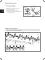
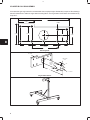
An automotive type engine stand is recommended when complete engine disassembly is required. See drawings
below for dimensions to make an engine stand mounting fixture. The engine stand shown below is manufactured by
Snap-OnR.
215 MM
65 MM
8 – 3/8”
HOLES
80 MM
60 MM
65 MM
45 MM
45 MM
50 MM
57 MM
39 MM
107 MM
Mounting Plate
1/2” THICK
THRU HOLE
21/32”
2 THRU
HOLES
13/32”
13”
5/8”
1–1/2”
1–1/2” DIA.
Engine Stand Fixture
2
5
CYLINDER BLOCK DISASSEMBLY
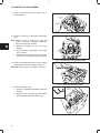
1. Remove cylinder head. See Sec. 2.
STARTER MOTOR
2. Remove oil pan, timing cover, gears and case. See
Sec. 3.
3. Remove flywheel and rear seal retainer. See
Sec. 4.
4. Remove starter motor, Fig. 1.
Fig. 1 – Removing Starter And Bracket
5. Remove alternator bracket and alternator, Fig. 2.
ALTERNATOR
BRACKET
Fig. 2 – Removing Alternator
6. Remove valve lifters, Fig. 3.
a. Number lifters so that they may be re-installed
in the same position.
VALVE LIFTER
Fig. 3 – Removing Valve Lifters
7. Remove camshaft, Fig. 4.
Note: Use care when removing camshaft to prevent
damaging cam bearing, journals and lobes.
CAMSHAFT
Fig. 4 – Removing Camshaft
3
5
CYLINDER BLOCK DISASSEMBLY
8. Remove oil pick-up tube and strainer, Fig. 5.
Discard gasket.
OIL PICK-UP
TUBE
Fig. 5 – Removing Oil Pick-Up
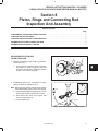
9. Remove connecting rod and piston assemblies,
Fig. 6.
Note: Remove carbon or ridge from cylinder and
number connecting rod/piston assemblies
before removing from cylinders.
a. Remove connecting rod cap with lower
bearing.
b. Push connecting rod and piston out through
top of cylinder.
c.
Reassemble connecting rod cap to connecting rod to prevent interchanging components.
Fig. 6 – Removing Connecting Rod Assembly
10. Remove crankshaft main bearing caps, keeping
main bearings with their respective caps, Fig. 7.
Note: Main bearing caps are numbered 1 through 4.
Fig. 7 – Removing Main Bearing Caps
11. Remove crankshaft, Fig. 8.
a. Remove crankshaft thrust washers (#3 main
bearing).
SHIMS
#3 MAIN
BEARING
b. Remove upper main bearings from saddles
and place with respective bearing caps.
Fig. 8 – Removing Crankshaft
4
6
BRIGGS & STRATTON DAIHATSU 3 CYLINDER
LIQUID-COOLED GASOLINE ENGINE REPAIR MANUAL (MS-0750)
Section 6
Cylinder Block Inspection And Repair
Section Contents
Page
CHECKING CYLINDER BLOCK . . . . . . . . . . . . . . . . . . . . . . . . . . . . . . . . . . . . . . . . . . . . . . . . . . . . . . . . . . . . . . . . . . . 1
REPLACING CAMSHAFT BEARING . . . . . . . . . . . . . . . . . . . . . . . . . . . . . . . . . . . . . . . . . . . . . . . . . . . . . . . . . . . . . . . 2
REPLACING CAMSHAFT PLUG . . . . . . . . . . . . . . . . . . . . . . . . . . . . . . . . . . . . . . . . . . . . . . . . . . . . . . . . . . . . . . . . . . . 3
CHECKING CYLINDER BLOCK
Remove all traces of sealant and gasket material from
mounting surfaces. Inspect cylinder block for damage,
cracks and stripped threads. Inspect cylinder bores for
damage or scores.
1. Check cylinder block deck for distortion, Fig. 1.
Distortion Limit:
0.08 mm (.003”)
Fig. 1 – Checking Cylinder Block
2. If cylinder block exceeds limit shown, it may be
resurfaced, Fig. 2.
Cylinder Block Height
Model Series 430000 Std:
229.20 – 229.80 mm
(9.023 – 9.047”)
Minimum Dimension:
(After Resurfacing)
229.10 mm (9.019”)
Model Series 580000 Std:
238.70 – 239.30 mm
(9.3976 – 9.421”)
Minimum Dimension:
(After Resurfacing)
238.60 mm (9.3937”)
Fig. 2 – Cylinder Block Height
SEPTEMBER, 2000
1
6
CYLINDER BLOCK INSPECTION AND REPAIR
3. Check cylinder bores for wear, Fig. 3.
MEASURE CYLINDER
BORE IN SIX
POSITIONS SHOWN
TO DETERMINE
TAPER & OUT OF
ROUND.
Standard Bore Size:
Model Series 430000
68.00 – 68.030 mm
(2.6770 – 2.6783”)
Model Series 580000
72.00 – 72.030 mm
(2.8346 – 2.8358”)
a. Measure cylinder bore in 6 points at right
angles as shown, Fig. 3.
b. If cylinder bore is worn more than 0.075 mm
(.003”) or more than 0.035 mm (.0015”) out of
round, it must be resized.
Always resize to exactly .25 mm (.010”) over standard
bore size. If this is done accurately, the service
oversize rings and pistons will fit perfectly and proper
clearances will be maintained.
TOP OF RING TRAVEL
(BELOW RIDGE)
CENTER OF RING TRAVEL
BOTTOM OF RING TRAVEL
AREA OF
NORMAL
WEAR
Fig. 3 – Checking Cylinder Bore
4. Check valve lifter bore, Fig. 4.
Std. Dimension:
Reject:
5. Check valve lifter, Fig. 4.
Std. Dimension:
Reject:
18.018 mm (.7093”)
18.05 mm (.711”)
17.98 mm (.708”)
17.91 mm (.705”)
Fig. 4 – Checking Valve Lifter And Bore
6. Check camshaft bearing, Fig. 5.
Replace if greater than 36.06 mm (1.420”).
Fig. 5 – Checking Cam Bearing
REPLACING CAMSHAFT BEARING
1. Remove camshaft bearing, Fig. 6.
a. Use camshaft bearing puller, Tool #19421.
Fig. 6 – Removing Cam Bearing
2
6
CYLINDER BLOCK INSPECTION AND REPAIR
2. Install camshaft bearing, Fig. 7.
a. Use camshaft bearing driver, Tool #19422.
Fig. 7 – Installing Cam Bearing
REPLACING CAMSHAFT PLUG
1. Remove rear camshaft plug, Fig. 8.
a. Use a wood dowel or brass rod to prevent
damage to camshaft bearing.
Fig. 8 – Removing Camshaft Plug
2. Install new camshaft plug using camshaft bearing
driver, Tool #19422.
a. Install camshaft plug flush with cylinder block,
Fig. 9.
Fig. 9 – Installing Camshaft Plug
If cylinder block is being resized, the following
parts should be removed so that cylinder
block may be thoroughly cleaned.
PLUG
1. Remove oil pressure switch, water gallery plug
and oil filter adapter, Fig. 10.
ADAPTER
SWITCH
Fig. 10 – Removing Oil Pressure Switch
3
6
CYLINDER BLOCK INSPECTION AND REPAIR
2. Remove timing gear oil nozzle, Fig. 11.
OIL NOZZLE
Fig. 11 – Removing Oil Nozzle
3. When reinstalling oil nozzle, oil hole must be positioned at 45° angle, pointing towards idler gear,
Fig. 12.
IDLER GEAR
Fig. 12 – Installing Oil Nozzle
4
7
BRIGGS & STRATTON DAIHATSU 3 CYLINDER
LIQUID-COOLED GASOLINE ENGINE REPAIR MANUAL (MS-0750)
Section 7
Crankshaft, Camshaft And Bearings
Section Contents
Page
CHECKING CRANKSHAFT . . . . . . . . . . . . . . . . . . . . . . . . . . . . . . . . . . . . . . . . . . . . . . . . . . . . . . . . . . . . . . . . . . . . . . . 1
CHECKING MAIN BEARING CLEARANCES . . . . . . . . . . . . . . . . . . . . . . . . . . . . . . . . . . . . . . . . . . . . . . . . . . . . . . . . 2
CHECKING CONNECTING ROD BEARING CLEARANCES . . . . . . . . . . . . . . . . . . . . . . . . . . . . . . . . . . . . . . . . . . . 3
CHECKING CRANKSHAFT END PLAY . . . . . . . . . . . . . . . . . . . . . . . . . . . . . . . . . . . . . . . . . . . . . . . . . . . . . . . . . . . . . 3
CHECKING CAMSHAFT . . . . . . . . . . . . . . . . . . . . . . . . . . . . . . . . . . . . . . . . . . . . . . . . . . . . . . . . . . . . . . . . . . . . . . . . . . 4
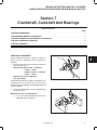
CHECKING CRANKSHAFT
Inspect crankshaft journals for grooves or signs of
scoring. If found, crankshaft must be re-ground or
replaced.
1. Check the main bearing and crankpin journals for
wear and taper, Fig. 1.
Standard size: Main: 41.976 – 42.000 mm
(1.6525 – 1.6535”)
Crankpin: 36.976 – 37.000 mm
(1.4557 – 1.4567”)
Maximum out of round and taper:
0.02 mm (0.0008”).
If crankshaft journals are not within specification, the
crankshaft may be re-ground and .25 mm (.010”)
undersize bearings installed. See illustrated parts list
for part numbers.
Fig. 1 – Checking Journals
2. Check the crankshaft for run-out at #3 main bearing journal, Fig. 2.
Maximum Run-out: 0.06 mm (0.0023”).
a. If run-out exceeds specification shown, the
crankshaft must be replaced.
Fig. 2 – Checking Run-out
SEPTEMBER, 2000
1
7
CRANKSHAFT, CAMSHAFT AND BEARINGS
3. Check crankshaft timing gear teeth for damaged
teeth, Fig. 3.
Note: See Section 3 for procedure to check crankshaft
timing gear for wear.
If crankshaft timing gear teeth are damaged or worn,
the crankshaft must be replaced.
Fig. 3 – Checking Timing Gear
CHECKING MAIN BEARING CLEARANCES
If main bearings show signs of flaking or scoring,
bearings must be replaced.
PLASTIGAGE
Main bearing saddles in cylinder block, main bearing
caps, main bearings and crankshaft journals must be
clean and free of oil.
1. With upper main bearings installed, install crankshaft.
a. Lay a strip of plastigage lengthwise on journal,
Fig. 4.
Do not lay plastigage across oil hole in crankshaft
journal.
Fig. 4 – Install Plastigage
2. Assemble main bearing cap with bearing and
torque to 61.0 Nm (45 ft. lbs.), Fig. 5.
DO NOT ALLOW CRANKSHAFT TO ROTATE.
Fig. 5 – Torque Bearing Cap
3. Remove the bearing cap. Measure the plastigage
at its widest point, Fig. 6. If the clearance is not
within specification, replace the bearings.
Crankshaft Main Bearing Clearance:
Std: 0.020 – 0.044 mm (0.0008 – 0.0017”)
Reject: 0.07 mm (0.0028”)
Repeat procedure for each main bearing.
Fig. 6 – Measure Clearance
2
7
CRANKSHAFT, CAMSHAFT AND BEARINGS
CHECKING CONNECTING ROD BEARING
CLEARANCES
PLASTIGAGE
If connecting rod bearings show signs of flaking or
scoring, bearings must be replaced.
Connecting rod bearings and crankpin journals must
be clean and free of oil.
1. With upper bearing assembled to connecting rod,
install connecting rod.
a. Lay a strip of plastigage lengthwise on journal,
Fig. 7.
Do not lay plastigage across oil hole in crankpin
journal.
Fig. 7 – Install Plastigage
2. Assemble connecting rod cap with bearing and
torque to 34.0 Nm (300 in. lbs.), Fig. 8.
DO NOT ALLOW CRANKSHAFT TO ROTATE.
Fig. 8 – Torque Rod Cap
3. Remove the connecting rod cap. Measure the
plastigage at its widest point, Fig. 9. If the clearance
is not within specification, replace the bearings.
Connecting Rod Bearing Clearance:
Std: 0.020 – 0.044 mm (0.0008 – 0.0017”)
Reject: 0.07 mm (0.0028”)
Repeat procedure for each connecting rod.
Fig. 9 – Measure Clearance
CHECKING CRANKSHAFT END PLAY
With thrust washers installed, check crankshaft end
play at #3 main bearing as shown, Fig. 10.
Crankshaft End Play:
Std: 0.020 – 0.23 mm (0.0008 – 0.009”)
Limit: 0.30 mm (0.012”)
If end play exceeds limit, .13 mm (.005”) over size
thrust washers are available. See illustrated parts list.
Fig. 10 – Checking Crankshaft End Play
3
7
CRANKSHAFT, CAMSHAFT AND BEARINGS
CHECKING CAMSHAFT
1. Measure camshaft lobe height, Fig. 11. If lobes are
not to specification, replace the camshaft.
Intake and Exhaust:
Std: 30.065 – 30.135 mm (1.183 – 1.186”)
Reject: 29.965 mm (1.179”)
Fig. 11 – Checking Camshaft Lobes
2. Measure camshaft journals, Fig. 12.
STD:
Front – 35.959 – 35.975 mm
(1.415 – 1.416”)
Reject: 35.890 mm (1.413”)
STD:
Center – 35.910 – 35.955 mm
(1.413 – 1.415”)
Reject: 35.84 mm (1.411”)
STD:
Rear – 35.910 – 35.955 mm
(1.413 – 1.415”)
Reject: 35.84 mm (1.411”)
Fig. 12 – Checking Camshaft Journals
3. Measure camshaft run-out, Fig. 13.
Maximum Run-out: 0.03 mm (0.0012”).
a. If run-out exceeds specification shown, the
camshaft must be replaced.
Fig. 13 – Checking Run-out
4
8
BRIGGS & STRATTON DAIHATSU 3 CYLINDER
LIQUID-COOLED GASOLINE ENGINE REPAIR MANUAL (MS-0750)
Section 8
Piston, Rings and Connecting Rod
Inspection And Assembly
Section Contents
Page
DISASSEMBLE PISTON AND CONNECTING ROD . . . . . . . . . . . . . . . . . . . . . . . . . . . . . . . . . . . . . . . . . . . . . . . . . . 1
CHECKING PISTON AND RINGS . . . . . . . . . . . . . . . . . . . . . . . . . . . . . . . . . . . . . . . . . . . . . . . . . . . . . . . . . . . . . . . . . . 2
CHECKING PISTON PIN AND CONNECTING ROD . . . . . . . . . . . . . . . . . . . . . . . . . . . . . . . . . . . . . . . . . . . . . . . . . . 2
ASSEMBLE PISTON AND CONNECTING ROD . . . . . . . . . . . . . . . . . . . . . . . . . . . . . . . . . . . . . . . . . . . . . . . . . . . . . 3
ASSEMBLE PISTON RINGS TO PISTON . . . . . . . . . . . . . . . . . . . . . . . . . . . . . . . . . . . . . . . . . . . . . . . . . . . . . . . . . . . 4
DISASSEMBLE PISTON AND
CONNECTING ROD
1. Remove compression rings using ring expander,
Tool #19340, Fig. 1.
a. Oil ring may be removed by hand by spiraling
top scraper into center ring groove, then into
top groove and off piston. Repeat for bottom
scraper. Then remove expander.
PISTON
Fig. 1 – Removing Piston Rings
2. Disassemble piston from connecting rod using
piston pin fixture, Tool #19419, Fig. 2.
Note: Piston pin stop must be removed from support
when disassembling piston and connecting rod.
a. Insert threaded driver through piston pin from
FRONT side of piston and thread into pilot.
STOP
FRONT
b. Place piston with driver onto support with
arrow on piston facing up.
c.
SUPPORT
Press out piston pin.
Fig. 2 – Disassembling Piston/Connecting Rod
SEPTEMBER, 2000
1
8
PISTON, RINGS AND CONNECTING ROD INSPECTION AND ASSEMBLY
CHECKING PISTON AND RINGS
If the cylinder bore is to be resized there is no reason to
check the piston as a new oversized piston will be
used.
If the cylinder is not going to be resized and the piston
shows no signs of scoring, the piston should be
checked.
1. Check side clearance of ring grooves using NEW
rings, Fig. 3. If a 0.11 mm (0.0045”) feeler gauge
can be inserted, the ring groove is worn. The
piston must be replaced.
NEW PISTON RING
Fig. 3 – Checking Ring Grooves
2. Check ring end gap, Fig. 4.
a. Clean carbon from end of rings and insert
approximately 25 mm (1”) into cylinder.
Ring End Gap Reject Size
Compression Rings
Oil Ring
0.53 mm (0.021”)
0.68 mm
(0.027”)
ÇÇ
ÇÇ
ÇÇ
Fig. 4 – Checking End Gap
3. Check piston pin bore, Fig. 5.
a. Replace if greater than 18.03 mm (0.710”) or
.01 mm (.0004”) out of round.
Fig. 5 – Checking Piston Pin Bore
CHECKING PISTON PIN AND
CONNECTING ROD
1. Check piston pin, Fig. 6.
a. Replace if less than 17.98 mm (0.708”) or .01
mm (.0004”) out of round.
Fig. 6 – Checking Piston Pin
2
8
PISTON, RINGS AND CONNECTING ROD INSPECTION AND ASSEMBLY
2. Check piston pin bearing, Fig. 7.
a. Replace if greater than 17.98 mm (0.708”) or
.01 mm (.0004”) out of round.
Fig. 7 – Checking Piston Pin Bearing
3. Check crankpin bearing end of connecting rod for
out of round, Fig. 8.
a. With bearing inserts removed, assemble connecting rod cap and torque to 33.9 Nm (300 in.
lbs.).
Maximum out of round: 0.02 mm (0.0008”).
b. If out of round exceeds specification shown,
the connecting rod must be replaced.
Fig. 8 – Checking Crankpin Bearing End
4. Check for bent or twisted connecting rod, Fig. 9.
Note: Thrust faces must be free of any burrs or nicks
or connecting rod will not lay flat on surface
plate.
a. With connecting rod on a surface plate, any
distortion will be evident by a rocking motion.
b. If a 0.05 mm (0.002”) feeler gauge can be
inserted at piston pin end of connecting rod the
rod must be replaced.
Fig. 9 – Checking Connecting Rod
ASSEMBLE PISTON AND
CONNECTING ROD
Assemble piston to connecting rod using piston pin
fixture, Tool #19419, Fig. 10.
Note: Arrow on piston and ID mark on rod must face
same side.
1. Lubricate piston pin with engine oil. Then, insert
threaded driver through piston pin and thread into
pilot.
a. With arrow on piston and ID mark on rod facing
up, insert pilot through piston and connecting
rod.
DRIVER
PISTON
PIN
ID
MARK
PILOT
Fig. 10 – Assembling Piston And Rod
3
8
PISTON, RINGS AND CONNECTING ROD INSPECTION AND ASSEMBLY
2. Insert piston pin stop in bottom of piston support,
Fig. 11.
a. With arrow on piston up, place assembly onto
support.
ID
MARKS
UP
STOP
b. Press in piston pin until pilot bottoms on stop.
FRONT
After assembly, make sure piston rotates freely on
connecting rod.
SUPPORT
Fig. 11 – Installing Piston Pin
ASSEMBLE PISTON RINGS TO PISTON
1. Install oil ring expander first.
a. Spiral bottom oil control ring into top ring
groove, center ring groove and then into position below expander, Fig. 12.
b. Repeat for upper oil control ring.
OIL CONTROL RING
EXPANDER
OIL CONTROL RING
Fig. 12 – Installing Oil Ring
2. Using ring expander, Tool #19340, install center
compression ring then, top compression ring with
ID marks up, Fig. 13.
ID
MARK
a. Stagger ring end gaps.
b. Rotate oil control ring ends 180° from each
other.
TOP
ID
MARK
CENTER
Fig. 13 – Installing Compression Rings
4
9
BRIGGS & STRATTON DAIHATSU 3 CYLINDER
LIQUID-COOLED GASOLINE ENGINE REPAIR MANUAL (MS-0750)
Section 9
Cylinder Block Assembly
Section Contents
Page
INSTALL CRANKSHAFT . . . . . . . . . . . . . . . . . . . . . . . . . . . . . . . . . . . . . . . . . . . . . . . . . . . . . . . . . . . . . . . . . . . . . . . . . . 1
INSTALL PISTONS AND CONNECTING RODS . . . . . . . . . . . . . . . . . . . . . . . . . . . . . . . . . . . . . . . . . . . . . . . . . . . . . . 2
GENERAL ASSEMBLY
Oil Pick-up Tube . . . . . . . . . . . . . . . . . . . . . . . . . . . . . . . . . . . . . . . . . . . . . . . . . . . . . . . . . . . . . . . . . . . . . . . . . . 3
Rear Seal Retainer and Starter Motor . . . . . . . . . . . . . . . . . . . . . . . . . . . . . . . . . . . . . . . . . . . . . . . . . . . . . . . 3
Flywheel . . . . . . . . . . . . . . . . . . . . . . . . . . . . . . . . . . . . . . . . . . . . . . . . . . . . . . . . . . . . . . . . . . . . . . . . . . . . . . . . 3
INSTALL TIMING GEAR CASE, CAMSHAFT AND GEARS . . . . . . . . . . . . . . . . . . . . . . . . . . . . . . . . . . . . . . . . . . . 4
INSTALL OIL PAN . . . . . . . . . . . . . . . . . . . . . . . . . . . . . . . . . . . . . . . . . . . . . . . . . . . . . . . . . . . . . . . . . . . . . . . . . . . . . . . 6
INSTALL ALTERNATOR . . . . . . . . . . . . . . . . . . . . . . . . . . . . . . . . . . . . . . . . . . . . . . . . . . . . . . . . . . . . . . . . . . . . . . . . . . 6
INSTALL CRANKSHAFT
GROOVES
OIL
HOLES
Install main bearings in cylinder block, Fig. 1.
Note: Upper bearing has an oil groove and oil holes.
1. Install upper main bearings in their respective
saddles.
a. Be sure bearing is seated in saddle and tang in
bearing is aligned with notch in saddle.
b. Lubricate bearings with engine oil.
Fig. 1 – Installing Upper Main Bearings
2. Install lower main bearings in bearing caps, Fig. 2.
a. Be sure bearing is seated in bearing cap and
tang in bearing is aligned with notch in bearing
cap.
b. Lubricate bearings with engine oil.
Fig. 2 – Installing Lower Main Bearings
SEPTEMBER, 2000
1
9
CYLINDER BLOCK ASSEMBLY
3. Install crankshaft with gear facing front of cylinder
block, Fig. 3. Take care not to damage journals or
bearings.
INSTALL
SHIMS
#3 MAIN
BEARING
a. Install crankshaft shims on #3 main bearing
web with grooves facing out.
b. Lubricate journals with engine oil.
Fig. 3 – Installing Crankshaft
4. Install main bearing caps, Fig. 4. Lubricate
threads of screws with engine oil.
ARROW
FRONT
3
2
#1
#2
1
4
a. Install bearing caps in their respective positions
with arrows facing front.
b. Starting with #3 bearing cap, torque bearing
caps one at a time in sequence shown to 61.0
Nm (45 ft. lbs.).
c.
#3
Recheck crankshaft end play.
Crankshaft End Play:
0.025 – 0.23 mm (0.001 – 0.009”)
Note: After torquing bearing cap, make sure crankshaft rotates freely before proceeding to next
bearing cap.
FRONT
Fig. 4 – Installing Main Bearing Caps
INSTALL PISTONS AND
CONNECTING RODS
VINYL TUBING
1. Install connecting rod bearings, Fig. 5. Be sure
tang on bearing is seated in notch in connecting
rod and cap.
NOTCH
a. Install a piece of vinyl tubing over each
connecting rod screw to prevent damage to
screw threads or crankpin when installing
piston and connecting rod.
ID MARK
Fig. 5 – Installing Connecting Rod Bearings
2
#4
9
CYLINDER BLOCK ASSEMBLY
Rotate crankshaft so that crankpin is at bottom of
stroke. Then, lubricate cylinder walls, piston and rings,
bearings and crankpins.
2. Using ring compressor, Tool #19070, install piston
and connecting rod assemblies with arrow on
piston facing front, Fig. 6.
a. Install connecting rod cap with ID mark facing
front. Lubricate threads and torque nuts to
36.0 Nm (320 in. lbs.).
Note: After torquing rod cap, make sure crankshaft
rotates freely before proceeding to next cylinder.
FRONT
ID MARK
Fig. 6 – Installing Piston And Connecting Rod
GENERAL ASSEMBLY
1. Install gasket, oil pick-up tube and strainer, Fig. 7.
a. Torque screws to 8.0 Nm (70 in. lbs.).
Fig. 7 – Installing Oil Pick Up
2. Install gasket and rear seal retainer, Fig. 8.
a. Torque screws to 6.0 Nm (50 in. lbs.).
3. Install starter motor.
a. Torque screws to 40.0 Nm (30 ft. lbs.).
REAR
SEAL
RETAINER
Fig. 8 – Installing Rear Seal Retainer
4. Install flywheel, Fig. 9.
a. Install flywheel holder, Tool #19418.
FLYWHEEL
HOLDER
b. Apply PermatexR No. 2 or similar sealant to
flywheel screws and torque to 47.0 Nm
(35 ft. lbs.).
Fig. 9 – Installing Flywheel
3
9
CYLINDER BLOCK ASSEMBLY
INSTALL TIMING GEAR CASE,
CAMSHAFT AND GEARS
1. Lubricate oil pump rotor with engine oil and install
in cylinder block, Fig. 10.
a. ID mark on rotor must face cylinder block.
ID MARK
OIL PUMP
ROTOR
Fig. 10 – Installing Oil Pump Rotor
2. Install timing gear case with new gasket.
B
Note: It may be necessary to rotate oil pump drive to
engage oil pump rotors.
Note position, length and number of screws as shown,
Fig. 11.
a. M6 x 28 mm (M6 x 1.1”): 4
b. M6 x 16 mm (M6 x 1.5”): 1
Torque screws to 8.0 Nm (70 in. lbs.).
A
Fig. 11 – Installing Gear Case
3. Lubricate, then install camshaft in cylinder block,
Fig. 12. Take care not to damage lobes or cam
bearing.
a. Install camshaft retainer.
b. M6 x 18 mm (M6 x 0.7”): 3
RETAINER
Torque screws to 8.0 Nm (70 in. lbs.).
Note: Position camshaft retainer so that center hole
does not interfere with camshaft.
Fig. 12 – Installing Camshaft
4. Rotate crankshaft so that crankshaft key is at
12 o’clock position as shown in Fig. 13.
CRANKSHAFT
KEY 12 O’CLOCK
Fig. 13 – Rotate Crankshaft
4
9
CYLINDER BLOCK ASSEMBLY
5. Assemble idler gear shaft with ID mark up, as
shown in Fig. 14.
ID MARK
UP
IDLER GEAR
SHAFT
Fig. 14 – Assemble Idler Gear Shaft
Engine models 430000 and 580000 after date code
990111007 are equipped with right angle helical timing
gears. Timing marks are identified by letters (A, AA, B,
BB, etc.), instead of numbers. The timing procedure is
the same.
6. With crankshaft key at 12 o’clock position,
assemble idler gear so that timing mark 11 (AA) is
aligned with timing mark 1 (A) on crankshaft gear,
timing mark 22 (BB) is aligned with timing mark 2
(B) on camshaft gear as shown in Fig. 15.
22
2
B
11
1
A
a. Install oil pump gear.
b. Install governor gear.
Fig. 15 – Aligning Timing Marks
7. Torque screws as shown, Fig. 16.
a. Camshaft gear: 41.0 Nm (30 ft. lbs.).
A
B
b. Idler gear: 25.0 Nm (220 in. lbs.).
c.
Oil pump gear: 19.0 Nm (170 in. lbs.).
C
Fig. 16 – Torque Screws
8. Install timing gear cover with new gasket. Note
position, length and number of screws as shown,
Fig. 17.
B
D
C
C
a. M6 x 65 mm (M6 x 2.5”): 2
b. M6 x 55 mm (M6 x 2.1”): 3
c.
A
D
M6 x 30 mm (M6 x 1.1”): 7
d. M6 Nuts: 2
C
Torque screws and nuts to 8.0 Nm (70 in. lbs.).
C
B
B
Fig. 17 – Installing Timing Cover
5
9
CYLINDER BLOCK ASSEMBLY
9. Install crankshaft pulley with timing mark at
12 o’clock position (#1 cylinder), Fig. 18.
TRIGGER
Note: Be sure alignment pin in crankshaft gear is
seated in hole in pulley.
a. Torque screw to 88.0 Nm (65 ft. lbs.).
b. Remove flywheel holder.
c.
Install trigger assembly and wire.
Fig. 18 – Installing Pulley
INSTALL OIL PAN
SEALANT
1. Install oil pan with new gasket, Fig. 19.
a. Apply a small bead of Permatex No. 2 or
similar sealant to crankcase areas shown.
b. Torque screws and nuts to 8.0 Nm (70 in. lbs.).
Fig. 19 – Installing Oil Pan
INSTALL ALTERNATOR
1. Install alternator bracket and alternator, Fig. 20.
a. Torque screws to 19.0 Nm (170 in. lbs.).
Fig. 20 – Install Alternator
GENERAL ASSEMBLY
1. Lubricate tappets with engine oil and install in
cylinder block.
2. See Section 2 for installation of cylinder head and
related components.
3. See Section 3 for governor adjustment procedure.
6
10
BRIGGS & STRATTON DAIHATSU 3 CYLINDER
LIQUID-COOLED GASOLINE ENGINE REPAIR MANUAL (MS-0750)
Section 10
Carburetor And Related Components
Section Contents
Page
MANUAL CHOKE CARBURETOR
REMOVE CARBURETOR . . . . . . . . . . . . . . . . . . . . . . . . . . . . . . . . . . . . . . . . . . . . . . . . . . . . . . . . . . . . . . . . . . . 3
DISASSEMBLE CARBURETOR . . . . . . . . . . . . . . . . . . . . . . . . . . . . . . . . . . . . . . . . . . . . . . . . . . . . . . . . . . . . . . 4
CLEAN AND INSPECT CARBURETOR . . . . . . . . . . . . . . . . . . . . . . . . . . . . . . . . . . . . . . . . . . . . . . . . . . . . . . . . 6
CHECK THROTTLE, CHOKE SHAFT AND BODY FOR WEAR . . . . . . . . . . . . . . . . . . . . . . . . . . . . . . . . . . . 6
ASSEMBLE CARBURETOR . . . . . . . . . . . . . . . . . . . . . . . . . . . . . . . . . . . . . . . . . . . . . . . . . . . . . . . . . . . . . . . . . 7
INSTALL CARBURETOR . . . . . . . . . . . . . . . . . . . . . . . . . . . . . . . . . . . . . . . . . . . . . . . . . . . . . . . . . . . . . . . . . . . . 8
CARBURETOR ADJUSTMENT . . . . . . . . . . . . . . . . . . . . . . . . . . . . . . . . . . . . . . . . . . . . . . . . . . . . . . . . . . . . . . . 9
AUTOMATIC CHOKE CARBURETOR . . . . . . . . . . . . . . . . . . . . . . . . . . . . . . . . . . . . . . . . . . . . . . . . . . . . . . . . . . . . . 10
REMOVE CARBURETOR . . . . . . . . . . . . . . . . . . . . . . . . . . . . . . . . . . . . . . . . . . . . . . . . . . . . . . . . . . . . . . . . . . 11
DISASSEMBLE CARBURETOR . . . . . . . . . . . . . . . . . . . . . . . . . . . . . . . . . . . . . . . . . . . . . . . . . . . . . . . . . . . . . 11
CLEAN AND INSPECT CARBURETOR . . . . . . . . . . . . . . . . . . . . . . . . . . . . . . . . . . . . . . . . . . . . . . . . . . . . . . . 14
CHECK THROTTLE, CHOKE SHAFT AND BODY FOR WEAR . . . . . . . . . . . . . . . . . . . . . . . . . . . . . . . . . . 14
ASSEMBLE CARBURETOR . . . . . . . . . . . . . . . . . . . . . . . . . . . . . . . . . . . . . . . . . . . . . . . . . . . . . . . . . . . . . . . . 15
CHECKING VACUUM CHOKE BREAK . . . . . . . . . . . . . . . . . . . . . . . . . . . . . . . . . . . . . . . . . . . . . . . . . . . . . . . 17
ADJUSTING CHOKE PRE-LOAD LEVER . . . . . . . . . . . . . . . . . . . . . . . . . . . . . . . . . . . . . . . . . . . . . . . . . . . . . 18
CHECKING P.T.C. HEATER . . . . . . . . . . . . . . . . . . . . . . . . . . . . . . . . . . . . . . . . . . . . . . . . . . . . . . . . . . . . . . . . . 18
INSTALL CARBURETOR . . . . . . . . . . . . . . . . . . . . . . . . . . . . . . . . . . . . . . . . . . . . . . . . . . . . . . . . . . . . . . . . . . . 18
INSTALL VACUUM LIMITER . . . . . . . . . . . . . . . . . . . . . . . . . . . . . . . . . . . . . . . . . . . . . . . . . . . . . . . . . . . . . . . . 18
CARBURETOR ADJUSTMENT . . . . . . . . . . . . . . . . . . . . . . . . . . . . . . . . . . . . . . . . . . . . . . . . . . . . . . . . . . . . . . 19
FUEL PUMP SPECIFICATIONS . . . . . . . . . . . . . . . . . . . . . . . . . . . . . . . . . . . . . . . . . . . . . . . . . . . . . . . . . . . . . . . . . . . 20
CHECKING FUEL PUMP OUTPUT . . . . . . . . . . . . . . . . . . . . . . . . . . . . . . . . . . . . . . . . . . . . . . . . . . . . . . . . . . . . . 21
TESTING FUEL PUMP WIRING . . . . . . . . . . . . . . . . . . . . . . . . . . . . . . . . . . . . . . . . . . . . . . . . . . . . . . . . . . . . . . . . 21
ANTI-AFTERFIRE SOLENOID . . . . . . . . . . . . . . . . . . . . . . . . . . . . . . . . . . . . . . . . . . . . . . . . . . . . . . . . . . . . . . . . . . . . 22
TESTING ANTI-AFTERFIRE SOLENOID . . . . . . . . . . . . . . . . . . . . . . . . . . . . . . . . . . . . . . . . . . . . . . . . . . . . . . . . 22
TESTING EQUIPMENT SOLENOID WIRING . . . . . . . . . . . . . . . . . . . . . . . . . . . . . . . . . . . . . . . . . . . . . . . . . . . . . 22
TESTING SOLENOID . . . . . . . . . . . . . . . . . . . . . . . . . . . . . . . . . . . . . . . . . . . . . . . . . . . . . . . . . . . . . . . . . . . . . . . . . 23
FUEL FILTER . . . . . . . . . . . . . . . . . . . . . . . . . . . . . . . . . . . . . . . . . . . . . . . . . . . . . . . . . . . . . . . . . . . . . . . . . . . . . . . . . . . 23
MAIN JET IDENTIFICATION . . . . . . . . . . . . . . . . . . . . . . . . . . . . . . . . . . . . . . . . . . . . . . . . . . . . . . . . . . . . . . . . . . . . . . 23
SEPTEMBER, 2000
1
10
Manual Choke Carburetor
Automatic Choke Carburetor
2
10
CARBURETOR AND RELATED COMPONENTS
MANUAL CHOKE CARBURETOR
REMOVE CARBURETOR
Disconnect fuel line. Remove air cleaner tube from
carburetor air horn. Disconnect fuel solenoid wire, if
equipped.
1. Unhook governor link spring from throttle lever and
disconnect governor link, Fig. 1.
GOVERNOR
LINK
CHOKE
LINK
SPRING
a. Disconnect choke link at choke lever. Proceed
to Step 4.
Note: Early style choke links were manufactured
with a “Z” bend, Fig. 3. To remove choke
link the governor control bracket must be
removed. Proceed to Steps 2 and 3.
FUEL
LINE
Fig. 1 – Remove Governor And Choke Link
2. Disconnect governor spring. Remove two screws
and governor control bracket from intake manifold,
Fig. 2.
CHOKE
LINK
GOVERNOR
CONTROL
BRACKET
GOVERNOR
SPRING
Fig. 2 – Removing Governor Control Bracket
3. Remove choke link from choke lever, Fig. 3.
“Z’’ BEND
CHOKE
LINK
Fig. 3 – Removing Choke Link – Early Style
3
10
CARBURETOR AND RELATED COMPONENTS
4. Remove nuts, air horn, carburetor and insulator,
Fig. 4. Discard gaskets.
INSULATOR
AIR
HORN
GASKET
Fig. 4 – Removing Carburetor
DISASSEMBLE CARBURETOR
1. Remove anti-afterfire solenoid or bowl screw,
washer and carburetor bowl, Fig. 5.
SOLENOID
BOWL
WASHER
BOWL
SCREW
Fig. 5 – Removing Bowl
2. Drive out float hinge pin from choke plate side of
carburetor with a small punch. Remove float and
fuel inlet valve, Fig. 6.
FLOAT
INLET
VALVE
HINGE
PIN
CHOKE
PLATE
SIDE
Fig. 6 – Removing Float
3. Remove carburetor bowl gasket, Fig. 7.
BOWL
GASKET
Fig. 7 – Removing Bowl Gasket
4
10
CARBURETOR AND RELATED COMPONENTS
4. Remove fixed high speed jet using screwdriver,
Tool #19062, Fig. 8.
FIXED JET
EMULSION
TUBE
a. Remove emulsion tube.
Note: Consult the illustrated parts list for correct part
number for special high altitude jet, if required.
Also, See page 23 for main jet identification
chart.
Fig. 8 – Removing High Speed Jet And Nozzle
5. Remove idle jet, Fig. 9.
IDLE JET
Fig. 9 – Removing Idle Jet
6. If idle mixture screw is equipped with adjustment
limiter cap, use a pliers to remove it before removing idle mixture valve.
SPRING
IDLE
MIXTURE
SCREW
a. Remove Idle mixture screw and spring, Fig. 10.
Fig. 10 – Removing Idle Mixture Screw
7. Remove screw and choke plate.
a. Remove choke shaft and spring, Fig. 11.
CHOKE
SHAFT
SPRING
Fig. 11 – Removing Choke Shaft
5
10
CARBURETOR AND RELATED COMPONENTS
Note: If engine is equipped with electronic governor
system, DO NOT remove throttle plate or throttle
shaft. This is a precision assembly and should not
be disassembled.
If engine is not equipped with electronic governor
proceed to step 8.
8. Mark throttle plate before removing so that it may
be re-installed in the same position. Sides of
throttle plate are beveled.
9
COLLAR
THROTTLE
SHAFT
SEAL
MARK
THROTTLE
PLATE
Remove two screws, throttle plate, throttle shaft
with collar and seal, Fig. 12.
a. Discard seal.
Fig. 12 – Removing Throttle Shaft
CLEAN CARBURETOR
Remove gasket material from mounting surfaces. Gummy or dirty carburetors should be cleaned in a carburetor
cleaner. DO NOT soak rubber, neoprene or plastic parts in cleaner.
IMPORTANT: If engine is equipped with electronic governor system, DO NOT clean carburetor in carburetor cleaner.
The carburetor is equipped with sealed ball bearings for the throttle shaft, which will be damaged if carburetor is
immersed in carburetor cleaner. Ball bearings are not replaceable.
INSPECT CARBURETOR
Inspect all parts for wear, cracks, nicks and burrs. Inspect float for leaks. Replace all damaged parts.
CHECK THROTTLE, CHOKE SHAFT AND
BODY FOR WEAR
1. Lay carburetor on flat surface and check throttle
and choke shaft clearance as shown in Fig. 13.
Throttle shaft and choke shaft clearance must not
exceed .25 mm (.010”).
Fig. 13 – Checking Clearance
2. Inspect throttle shaft and choke shaft for wear,
Fig. 14.
WORN
Replace if worn.
If carburetor body is worn, replace carburetor.
Fig. 14 – Checking Throttle Shaft Wear
6
10
CARBURETOR AND RELATED COMPONENTS
ASSEMBLE CARBURETOR
COLLAR
When assembling carburetor, use new seals and
gaskets.
1. Install throttle shaft, Fig. 15.
GROOVE
OUT
a. Install seal with grooved side out.
b. Assemble collar to throttle shaft and insert in
body.
c.
Install throttle plate and screws.
Note: Use LOCTITE 222 on screw threads.
Fig. 15 – Installing Throttle Shaft
2. Install choke valve, Fig. 16.
ROTATE
CLOCKWISE
TO PRELOAD
SPRING
a. Assemble spring to choke shaft and insert in
body.
b. Rotate shaft clockwise to pre-load spring.
c.
Install choke plate with hole facing fuel inlet
side of body.
Note: Use LOCTITE 222 on screw threads.
Fig. 16 – Installing Choke Shaft
3. Assemble the following parts, Fig. 17:
a. Emulsion tube.
IDLE JET
EMULSION
TUBE
b. Fixed high speed jet using screwdriver, Tool
#19062
c.
FIXED
JET
Idle jet.
Fig. 17 – Installing Nozzle And Jets
4. Install float, Fig. 18.
a. Assemble inlet valve to float.
INLET
VALVE
b. Install float hinge pin from throttle plate side of
carburetor.
HINGE
PIN
Fig. 18 – Install Float
7
10
CARBURETOR AND RELATED COMPONENTS
5. Install gasket and float bowl, Fig. 19.
GASKET
SOLENOID
BOWL
WASHER
SCREW
Fig. 19 – Install Float Bowl
6. Install idle mixture screw and spring, Fig. 20.
DO NOT tighten idle mixture screw.
SPRING
IDLE
MIXTURE
SCREW
Fig. 20 – Install Idle Mixture Screw
INSTALL CARBURETOR
1. Assemble insulator with gaskets, carburetor and
air horn with gasket to intake manifold, Fig. 21.
Torque nuts to 8.0 Nm (70 in. lbs.).
a. Install governor link and spring.
INSULATOR
AIR
HORN
GASKET
b. Install choke link.
Note: Proceed to Step 2 if choke link is early style
with “Z” bend.
Reinstall air cleaner tube and fuel line.
Fig. 21 – Install Carburetor
2. Install choke link.
a. Assemble governor control bracket to intake
manifold, Fig. 22.
Torque screws to 8.0 Nm (70 in. lbs.).
b. Assemble governor spring to governor control
lever.
Important: Governor spring must be installed in correct
hole in governor control lever by engine model.
a. Model 430400 – Top Hole
b. Model 580400 – Bottom Hole
Reinstall air cleaner tube and fuel line.
8
CHOKE
LINK
GOVERNOR
CONTROL
BRACKET
MODEL 430400
TOP HOLE
MODEL 580400
BOTTOM HOLE
GOVERNOR
SPRING
Fig. 22 – Install Governor Control Lever
10
CARBURETOR AND RELATED COMPONENTS
INITIAL CARBURETOR ADJUSTMENT
Turn idle mixture screw clockwise until it just seats. DO
NOT FORCE. Turn screw counter-clockwise 1/2 turn,
Fig. 23. This setting will permit engine to start.
Final adjustment will be made with engine running.
1/2 TURN
Fig. 23 – Initial Carburetor Adjustment
FINAL CARBURETOR ADJUSTMENT
THROTTLE
LEVER
ALL CARBURETOR ADJUSTMENTS MUST BE
MADE WITH THE AIR CLEANER INSTALLED.
Start and run engine at low speed for approximately
five minutes. Or, if equipped with temperature gauge,
until needle moves from C or COLD position.
1. With control lever on equipment in SLOW position, hold throttle lever against idle speed screw
and adjust idle speed to 1200 RPM, Fig. 24.
Fig. 24 – Adjusting Idle Speed
2. SLOWLY turn idle mixture screw clockwise until
engine speed just starts to slow (lean mixture).
3. Then SLOWLY turn idle mixture screw counterclockwise until engine speed just starts to slow
(rich mixture).
KNOCK
OUT
PIN TOOL
#19135
4. Turn idle mixture screw to mid point between rich
and lean, Fig. 25.
5. Hold throttle lever against idle speed screw and
re-adjust idle speed to 1500 RPM, or equipment
manufacturers specification.
LIMITER
CAP
MID POINT
6. IF CARBURETOR IS EQUIPPED WITH AN IDLE
MIXTURE LIMITER CAP, INSTALL AT THIS TIME.
a. Position limiter cap so that stop(s) on limiter
cap are at mid point between stop(s) on carburetor body and press into position as shown in,
Fig. 25.
RICH
LEAN
Fig. 25 – Adjusting Idle Mixture
9
10
CARBURETOR AND RELATED COMPONENTS
AUTOMATIC CHOKE CARBURETOR
The automatic choke consists of a vacuum choke break and a thermostat. Intake manifold vacuum activates the
vacuum choke break which partially opens the choke plate, to prevent over choking while the engine is being started.
A vacuum limiter located in the vacuum line regulates vacuum to the vacuum choke break.
The thermostat contains a P.T.C. heater and a bi-metal spring which opens the choke plate gradually as the engine is
running. When the keyswitch is turned ‘‘ON,” battery current activates the P.T.C. heater which heats the bi-metal
spring.
The P.T.C. Heater (an abbreviation of positive temperature coefficient heater), is a heat sensitive semiconductor
porcelain. As the P.T.C. heater temperature rises, resistance increases, which regulates battery current to the heater
and maintains the proper temperature for the bi-metal spring.
SPRING
THERMOSTAT
P.T.C. HEATER
CARBON SEAT
STUD
VACUUM
CHOKE
BREAK
BI-METAL SPRING
Wiring Diagram
Standard
VACUUM
LIMITER
Wiring Diagram
Optional
ELECTRIC CHOKE
RELAY
ELECTRIC CHOKE
A
S
B
KEYSWITCH
A
S
B
T
G
B+
F
#1
T1
T2
#2
#3
KEYSWITCH
12 VOLT BATTERY
IGNITION MODULE
12 VOLT BATTERY
10
10
CARBURETOR AND RELATED COMPONENTS
AUTOMATIC CHOKE CARBURETOR
REMOVE CARBURETOR
VACUUM LINE
GOVERNOR
LINK
SPRING
Disconnect fuel line and remove air cleaner tube from
carburetor air horn. Disconnect vacuum line from
vacuum choke break. Disconnect wires from fuel shut
off solenoid and automatic choke.
1. Unhook governor link spring from throttle lever and
disconnect governor link, Fig. 26.
Fig. 26 – Remove Governor Link And Spring
2. Remove two nuts and ground wire from solenoid,
air horn, carburetor and insulator, Fig. 27. Discard
gaskets.
INSULATOR
AIR HORN
GROUND WIRE
Fig. 27 – Removing Carburetor
DISASSEMBLE CARBURETOR
1. Remove fuel shut off solenoid and gasket.
Remove float bowl and bowl shim gasket, Fig. 28.
BOWL SHIM
GASKET
Fig. 28 – Removing Float Bowl
11
10
CARBURETOR AND RELATED COMPONENTS
Note: Float hinge pin is swaged on one side. When
removing, drive hinge pin from side opposite
swage.
2. Drive out float hinge pin with a small punch.
Remove float and fuel inlet valve, Fig. 29.
IDLE PASSAGE
PLUG
3. Remove idle passage plug, Fig. 29.
Fig. 29 – Removing Float And Idle Passage Plug
4. Remove rubber float bowl gasket, Fig. 30.
BOWL GASKET
Fig. 30 – Removing Gasket
5. Remove fixed main jet and gasket, Fig. 31. Discard
gasket.
Note: Consult the illustrated parts list for correct part
number for special high altitude jet, if required.
Also, See page 23 for main jet identification
chart.
MAIN JET AND
GASKET
Fig. 31 – Removing Main jet
6. Remove three screws, thermostat retainer and
ground wire, Fig. 32. Discard thermostat gasket.
RETAINER
THERMOSTAT
GROUND WIRE
GASKET
Fig. 32 – Removing Thermostat
12
10
CARBURETOR AND RELATED COMPONENTS
7. Remove screw and choke pre-load lever, Fig. 33.
CHOKE SHAFT
8. Remove two screws, choke plate and choke shaft,
Fig. 33.
CHOKE PRELOAD
LEVER
Fig. 33 – Removing Choke Shaft
9. Remove two screws and vacuum choke break,
Fig. 34.
VACUUM BREAK
Fig. 34 – Removing Choke Vacuum Break
10. Remove idle jet plug and idle jet, Fig. 35.
IDLE JET PLUG
AND IDLE JET
Fig. 35 – Removing Idle Jet
11. Remove idle mixture screw and ‘‘O”-ring, Fig. 36.
Discard ‘‘O”-ring.
IDLE MIXTURE
SCREW
AND O-RING
Fig. 36 – Removing Idle Mixture Screw
13
10
CARBURETOR AND RELATED COMPONENTS
Note: If engine is equipped with electronic governor
system, DO NOT remove throttle plate or
throttle shaft. This is a precision assembly and
should not be disassembled.
If engine is not equipped with electronic governor
proceed to step 12.
12. Mark throttle plate before removing so that it may
be re-installed in the same position. Sides of
throttle plate are beveled.
MARK THROTTLE
VALVE
SEAL
13. Remove two screws, throttle plate, throttle shaft
and seal, Fig. 37.
a. Discard seal.
Fig. 37 – Removing Throttle Shaft
CLEAN CARBURETOR
Remove gasket material from mounting surfaces. Gummy or dirty carburetors should be cleaned in a carburetor
cleaner. DO NOT soak rubber, neoprene or plastic parts in cleaner.
IMPORTANT: If engine is equipped with electronic governor system, DO NOT clean carburetor in carburetor cleaner.
The carburetor is equipped with sealed ball bearings for the throttle shaft, which will be damaged if carburetor is
immersed in carburetor cleaner. Ball bearings are not replaceable.
INSPECT CARBURETOR
Inspect all parts for wear, cracks, nicks and burrs. Inspect float for leaks. Replace all damaged parts.
CHECK THROTTLE, CHOKE SHAFT AND
BODY FOR WEAR
1. Lay carburetor on flat surface and check throttle
and choke shaft clearance as shown in Fig. 38.
Throttle shaft and choke shaft clearance must not
exceed .25 mm (.010”).
Fig. 38 – Checking Clearance
2. Inspect throttle shaft and choke shaft for wear,
Fig. 39.
Replace if worn.
If carburetor body is worn, replace carburetor.
WORN
Fig. 39 – Checking Throttle Shaft
14
10
CARBURETOR AND RELATED COMPONENTS
ASSEMBLE CARBURETOR
When assembling carburetor, use new seals and
gaskets.
1. Install throttle shaft and new seal, Fig. 40.
a. Install throttle plate and screws.
Note: Use LOCTITE 222 on screw threads.
SEAL
Fig. 40 – Installing Throttle Shaft
2. Install idle mixture screw with new ‘‘O”-ring,
Fig. 41.
DO NOT tighten idle mixture screw.
IDLE MIXTURE
SCREW
AND O-RING
Fig. 41 – Installing Idle Mixture Screw
3. Install idle jet and plug, Fig. 42.
IDLE JET AND
IDLE JET PLUG
Fig. 42 – Installing Idle Jet
4. Assemble vacuum choke break to bracket, Fig. 43.
Note correct position of pivot arm, Fig. 43.
PIVOT ARM
VACUUM BREAK
Fig. 43 – Assemble Vacuum Choke Breaker
15
10
CARBURETOR AND RELATED COMPONENTS
5. Install choke shaft through pivot arm bushing and
into carburetor body, Fig. 44.
2.5 MM (3/32”)
Note: Specification between arms: 2.5 mm
(3/32”).
6. Install choke plate.
Note: Use LOCTITE 222 on screw threads.
Fig. 44 – Installing Choke Shaft
7. Install thermostat with new gasket, Fig. 45.
a. Insert hook on thermostat spring between
arms on choke shaft.
b. Assemble thermostat retainer leaving screws
loose.
Fig. 45 – Installing Thermostat
8. Hold choke plate closed and rotate thermostat
until match marks are aligned, Fig. 46.
a. Tighten screws.
Note: Make sure choke plate remains closed while
pre-loading thermostat spring.
Fig. 46 – Pre-loading Thermostat Spring
9. Assemble choke pre-load lever to choke shaft,
Fig. 47.
PRE LOAD
LEVER
Fig. 47 – Assembling Pre-load Lever
16
10
CARBURETOR AND RELATED COMPONENTS
10. Install float, Fig. 48.
a. Assemble inlet valve to float.
b. Install float hinge pin.
c.
Install idle passage plug.
d. Install fixed main jet with new gasket.
e. Install new bowl gasket.
Fig. 48 – Installing Float
11. Install float bowl with new gaskets, Fig. 49.
BOWL SHIM
GASKET
SOLENOID
GASKET
Fig. 49 – Install Float Bowl
CHECKING VACUUM CHOKE BREAK
A Mityvac vacuum pump or equivalent is required
when checking and adjusting the vacuum choke
break.
1. Connect vacuum pump to choke break and activate
pump to specification shown.
Specification:
10.0 – 14.0 cm. Hg. vac.
(4.0 – 5.5 in. Hg. vac.)
Choke plate should partially open and pump gauge
should maintain vacuum.
Fig. 50 – Checking Choke
2. Check dimension from edge of choke plate to edge
of carburetor throat, Fig. 51.
Specification:
14.0 – 15.0 mm
(.550 – .590”).
EDGE OF
CARBURETOR
THROAT
If dimension is not to specification the choke pre-load
lever must be adjusted.
Fig. 51 – Checking Choke
17
10
CARBURETOR AND RELATED COMPONENTS
ADJUSTING CHOKE PRE-LOAD LEVER
1. Release vacuum pump so that choke closes.
PRE-LOAD
LEVER
2. Manually open choke to end of travel and hold in
this position.
3. Carefully bend pre-load lever, Fig. 52:
a. Bend lever to left to increase dimension.
DECREASE
b. Bend lever to right to decrease dimension.
INCREASE
Re-check and adjust as necessary.
Fig. 52 – Adjusting Choke
CHECKING P.T.C. HEATER
The digital multimeter, Tool #19464 is required to test
the P.T.C. heater.
The following test will be made with the meter in the Ω
position.
1. Check resistance between tab terminal on thermostat and ground wire as shown, Fig. 53.
Specification: 2.0 – 40.0 Ω
@ (70_
F)
Replace thermostat if not to specification.
Fig. 53 – Checking Thermostat
INSTALL CARBURETOR
1. Assemble insulator with gaskets, carburetor and
air horn with gasket to intake manifold, Fig. 54.
Note: Attach thermostat ground wire to air horn as
shown.
Torque nuts to 8.0 Nm (70 in. lbs.).
2. Install governor link and governor link spring.
Reinstall air cleaner tube, vacuum line, harness
connectors and fuel line.
GROUND WIRE
Fig. 54 – Installing Carburetor
INSTALL VACUUM LIMITER
To install vacuum limiter on engines not originally
equipped with vacuum limiter, proceed as follows.
1. Cut vacuum line approximately 50 mm (2”) from
vacuum break side and install vacuum limiter with
blue end facing intake manifold, Fig. 55.
50 MM
(2”)
BLUE END
TOWARDS
MANIFOLD
VACUUM
LINE
Fig. 55 – Installing Vacuum Limiter
18
10
CARBURETOR AND RELATED COMPONENTS
INITIAL CARBURETOR ADJUSTMENT
Turn idle mixture screw clockwise until it just seats. DO
NOT FORCE. Turn screw counter-clockwise 1-1/4
turn, Fig. 56. This setting will permit engine to start.
Final adjustment will be made with engine running.
1-1/4 TURN
Fig. 56 – Initial Carburetor Adjustment
FINAL CARBURETOR ADJUSTMENT
ALL CARBURETOR ADJUSTMENTS MUST BE
MADE WITH THE AIR CLEANER INSTALLED.
THROTTLE
LEVER
Start and run engine at low speed for approximately
five minutes. Or, if equipped with temperature gauge,
until needle moves from C or COLD position.
1. With control lever on equipment in SLOW position,
hold throttle lever against idle speed screw and
adjust idle speed to 1200 RPM, Fig. 57.
Fig. 57 – Adjusting Idle Speed
2. SLOWLY turn idle mixture screw clockwise until
engine speed just starts to slow (lean mixture).
3. Then SLOWLY turn idle mixture screw counterclockwise until engine speed just starts to slow
(rich mixture).
4. Turn idle mixture screw to mid point between rich
and lean, Fig. 58.
5. Hold throttle lever against idle speed screw and
re-adjust idle speed to 1500 RPM.
Fig. 58 – Adjusting Idle Mixture
19
10
CARBURETOR AND RELATED COMPONENTS
Electric Fuel Pump
FUEL PUMP
CONNECTOR
EQUIPMENT WIRING HARNESS
CONNECTOR
New Style Pump
Old Style Pump
Fuel Pump Specifications
New Style Pump
Old Style Pump
USED AFTER 97033100
USED BEFORE 97040100
Type
12 Volt Electro magnetic
Delivery Output-Minimum
800 cc/minute (27 fl. oz.)
Fuel Pump Pressure-Maximum
0.25 Bar (3.5 psi)
12 Volt Electro magnetic
350 cc/minute (12 fl. oz.)
0.25 Bar (3.5 psi)
IMPORTANT: For proper fuel pump operation and fuel flow, fuel pump should be installed lower than fuel tank in as
vertical a position as possible (outlet side up). See figure below. Mount fuel pump away from sources of heat.
Carburetor
Install Pump Below
Lowest Fuel Level Of Tank
Install Vertically
Fuel Tank
Fuel Filter
Fuel Pump
Part #498688
Keep Fuel Line From Tank To
Pump As Short As Possible
20
Pump Can Push Fuel
6.5 Ft. Vertically
10
CARBURETOR AND RELATED COMPONENTS
CHECKING FUEL PUMP OUTPUT
A graduated container is required when testing the fuel
pump.
1. Disconnect fuel line at carburetor.
2. Turn ignition switch to ON position and note fuel
flow into graduated container.
a. If fuel flow is less than specification shown in
table above, replace fuel pump.
Note: A plugged fuel filter and/or low battery voltage
may cause insufficient fuel flow.
If there is no fuel flow when keyswitch is in ON position,
check fuel pump wiring.
Fig. 59 – Checking Fuel Pump Output
TEST EQUIPMENT
The digital multimeter, Tool #19464 is required to test
fuel pump.
The fuel pump test will be performed with the meter in
the V
(DC volts) position, Fig. 60.
Fig. 60 – Digital Multimeter
TESTING FUEL PUMP WIRING
1. With keyswitch in OFF position, disconnect fuel
pump equipment wiring harness connector.
2. Insert meter test leads into wiring harness connector as shown in Fig. 61. Then turn keyswitch to ON
position.
EQUIPMENT WIRING
HARNESS CONNECTOR
+
a. Meter should display battery voltage at connector.
If meter does not display battery voltage, problem is
with wiring harness and/or fuel pump relay (as
supplied by equipment manufacturer), and/or ignition
module. Also, check for loose or broken wires.
–
Fig. 61 – Checking Wiring
21
10
CARBURETOR AND RELATED COMPONENTS
ANTI-AFTERFIRE SOLENOID
Some carburetors are equipped with an Anti-Afterfire solenoid controlled by the equipment ignition switch. When the
equipment switch is in the “Off” position, the solenoid valve plunger closes, stopping fuel flow through the fixed main jet
or high speed nozzle. When the switch is in the “On” and “Start” position, the solenoid valve opens, allowing normal fuel
flow. Solenoid is operating properly if a click is heard when equipment ignition switch is turned “On” and “Off.” If
solenoid is not working (defective solenoid or equipment wiring), the engine will not start or run.
Note:
Anti-afterfire solenoid requires a minimum of 9 volts DC to function.
Important: Engines equipped with anti-afterfire solenoid are equipped with an air horn gasket with a ground
clip imbedded in the gasket, Fig. 62. Anti-afterfire
solenoid will not function if ground clip is removed or
damaged.
GROUND CLIP
Fig. 62 – Air Horn Gasket With Ground Clip
TESTING ANTI-AFTERFIRE SOLENOID
If solenoid does not click, the problem may be in
equipment wiring. To determine whether problem is
with wiring, perform this test.
TEST EQUIPMENT
The digital multimeter, Tool #19464 is required to test
the solenoid equipment wiring.
The wiring test will be performed with the meter in the
(DC volts) position, Fig. 63.
V
Fig. 63 – Digital Multimeter
TESTING EQUIPMENT SOLENOID WIRING
1. With keyswitch in OFF position, disconnect equipment wiring harness connector from solenoid.
EQUIPMENT WIRING HARNESS CONNECTOR
2. Insert red meter test lead into wiring harness connector and attach black test lead to a good ground,
Fig. 64.
3. Turn keyswitch to ON position.
a. Meter should display battery voltage at connector. Test solenoid.
If meter does not display battery voltage, problem is
with wiring harness. Check for loose or broken wire.
Fig. 64 – Checking Wiring
22
10
CARBURETOR AND RELATED COMPONENTS
TESTING SOLENOID
1. Remove solenoid from carburetor.
2. Place either terminal of a 9 volt transistor battery
on the solenoid connector and other terminal on
body of solenoid or ground wire.
+
a. Plunger should retract freely.
9
+
b. When battery is removed, plunger should
return freely.
–
VOLTS
Replace solenoid if plunger sticks or doesn’t move.
–
Fig. 65 – Checking Solenoid
FUEL FILTER
Replace inline fuel filter every 600 hours.
Inline fuel filter has an arrow to indicate fuel flow
direction. Always install with arrow towards carburetor.
Fig. 66 – Fuel Filter
CARBURETOR MAIN JETS
IDENTIFICATION NUMBER
The carburetor main jet orifice size is stamped in the
body of the jet, Fig. 67. See chart below for identification numbers and suggested application.
x
x
Fig. 67 – Main Jet Identification
*Std. Jet
Carburetor
0 – 4000 Ft.
(0 – 1220 m)
*High Altitude
3500 – 7000 Ft.
(1067 – 2134 m)
**High Altitude
7000 – 10,000 Ft.
(2134 – 3048 m)
Standard Choke
(700 G)
# 106
# 102
#98
Automatic Choke
(700 G)
# 128
# 120
#112
Standard Choke
(950 G)
# 114
# 110
#106
* See Illustrated Parts List For Correct Part Number
** Special Applications Only – Contact Source Of Supply
23
11
BRIGGS & STRATTON DAIHATSU 3 CYLINDER
LIQUID-COOLED GASOLINE ENGINE REPAIR MANUAL (MS-0750)
Section 11
Electrical Systems
Ignition System – Charging Systems – Starter System
Section Contents
Page
IGNITION SYSTEM COMPONENTS . . . . . . . . . . . . . . . . . . . . . . . . . . . . . . . . . . . . . . . . . . . . . . . . . . . . . . . . . . . . . . . . 2
TEST EQUIPMENT . . . . . . . . . . . . . . . . . . . . . . . . . . . . . . . . . . . . . . . . . . . . . . . . . . . . . . . . . . . . . . . . . . . . . . . . . . . . . . . 3
TESTING TRIGGER . . . . . . . . . . . . . . . . . . . . . . . . . . . . . . . . . . . . . . . . . . . . . . . . . . . . . . . . . . . . . . . . . . . . . . . . . . . . . . 3
TESTING IGNITION MODULE . . . . . . . . . . . . . . . . . . . . . . . . . . . . . . . . . . . . . . . . . . . . . . . . . . . . . . . . . . . . . . . . . . . . . 4
TESTING IGNITION COILS . . . . . . . . . . . . . . . . . . . . . . . . . . . . . . . . . . . . . . . . . . . . . . . . . . . . . . . . . . . . . . . . . . . . . . . 6
14 AMP CHARGING SYSTEM . . . . . . . . . . . . . . . . . . . . . . . . . . . . . . . . . . . . . . . . . . . . . . . . . . . . . . . . . . . . . . . . . . . . . 6
14 AMP WIRING DIAGRAM . . . . . . . . . . . . . . . . . . . . . . . . . . . . . . . . . . . . . . . . . . . . . . . . . . . . . . . . . . . . . . . . . . . . . . . 7
TEST EQUIPMENT . . . . . . . . . . . . . . . . . . . . . . . . . . . . . . . . . . . . . . . . . . . . . . . . . . . . . . . . . . . . . . . . . . . . . . . . . . . . . . . 8
TESTING ALTERNATOR – AC OUTPUT . . . . . . . . . . . . . . . . . . . . . . . . . . . . . . . . . . . . . . . . . . . . . . . . . . . . . . . . . . . . 8
TESTING REGULATOR-RECTIFIER – DC OUTPUT . . . . . . . . . . . . . . . . . . . . . . . . . . . . . . . . . . . . . . . . . . . . . . . . . . 8
CHARGING INDICATOR CIRCUIT . . . . . . . . . . . . . . . . . . . . . . . . . . . . . . . . . . . . . . . . . . . . . . . . . . . . . . . . . . . . . . . . . 9
TESTING CHARGING INDICATOR BULB AND WIRING . . . . . . . . . . . . . . . . . . . . . . . . . . . . . . . . . . . . . . . . . . . . . . 9
40 AMP WIRING DIAGRAM . . . . . . . . . . . . . . . . . . . . . . . . . . . . . . . . . . . . . . . . . . . . . . . . . . . . . . . . . . . . . . . . . . . . . . 10
40 AMP CHARGING SYSTEM . . . . . . . . . . . . . . . . . . . . . . . . . . . . . . . . . . . . . . . . . . . . . . . . . . . . . . . . . . . . . . . . . . . . 11
TEST EQUIPMENT . . . . . . . . . . . . . . . . . . . . . . . . . . . . . . . . . . . . . . . . . . . . . . . . . . . . . . . . . . . . . . . . . . . . . . . . . . . . . . 11
TESTING ALTERNATOR – DC OUTPUT . . . . . . . . . . . . . . . . . . . . . . . . . . . . . . . . . . . . . . . . . . . . . . . . . . . . . . . . . . . 11
DISASSEMBLE ALTERNATOR . . . . . . . . . . . . . . . . . . . . . . . . . . . . . . . . . . . . . . . . . . . . . . . . . . . . . . . . . . . . . . . . . . . 12
CHECKING BEARINGS . . . . . . . . . . . . . . . . . . . . . . . . . . . . . . . . . . . . . . . . . . . . . . . . . . . . . . . . . . . . . . . . . . . . . . . . . 13
INSTALL BALL BEARING . . . . . . . . . . . . . . . . . . . . . . . . . . . . . . . . . . . . . . . . . . . . . . . . . . . . . . . . . . . . . . . . . . . . . . . 14
CHECKING ROTOR . . . . . . . . . . . . . . . . . . . . . . . . . . . . . . . . . . . . . . . . . . . . . . . . . . . . . . . . . . . . . . . . . . . . . . . . . . . . . 14
CHECK BRUSHES . . . . . . . . . . . . . . . . . . . . . . . . . . . . . . . . . . . . . . . . . . . . . . . . . . . . . . . . . . . . . . . . . . . . . . . . . . . . . . 14
CHECK REGULATOR . . . . . . . . . . . . . . . . . . . . . . . . . . . . . . . . . . . . . . . . . . . . . . . . . . . . . . . . . . . . . . . . . . . . . . . . . . . 15
CHECK RECTIFIER . . . . . . . . . . . . . . . . . . . . . . . . . . . . . . . . . . . . . . . . . . . . . . . . . . . . . . . . . . . . . . . . . . . . . . . . . . . . . 15
ASSEMBLE ALTERNATOR . . . . . . . . . . . . . . . . . . . . . . . . . . . . . . . . . . . . . . . . . . . . . . . . . . . . . . . . . . . . . . . . . . . . . . 15
STARTER SYSTEM . . . . . . . . . . . . . . . . . . . . . . . . . . . . . . . . . . . . . . . . . . . . . . . . . . . . . . . . . . . . . . . . . . . . . . . . . . . . . 18
STARTER CURRENT DRAW TEST . . . . . . . . . . . . . . . . . . . . . . . . . . . . . . . . . . . . . . . . . . . . . . . . . . . . . . . . . . . . . . . 18
TEST EQUIPMENT . . . . . . . . . . . . . . . . . . . . . . . . . . . . . . . . . . . . . . . . . . . . . . . . . . . . . . . . . . . . . . . . . . . . . . . . . . . . . . 18
TESTING STARTER . . . . . . . . . . . . . . . . . . . . . . . . . . . . . . . . . . . . . . . . . . . . . . . . . . . . . . . . . . . . . . . . . . . . . . . . . . . . . 19
NO LOAD STARTER CURRENT DRAW TEST . . . . . . . . . . . . . . . . . . . . . . . . . . . . . . . . . . . . . . . . . . . . . . . . . . . . . . 19
EQUIPMENT TO TEST SOLENOID . . . . . . . . . . . . . . . . . . . . . . . . . . . . . . . . . . . . . . . . . . . . . . . . . . . . . . . . . . . . . . . . 20
TESTING SOLENOID . . . . . . . . . . . . . . . . . . . . . . . . . . . . . . . . . . . . . . . . . . . . . . . . . . . . . . . . . . . . . . . . . . . . . . . . . . . . 20
REMOVING PINION GEAR ASSEMBLY . . . . . . . . . . . . . . . . . . . . . . . . . . . . . . . . . . . . . . . . . . . . . . . . . . . . . . . . . . . 21
INSTALL PINION GEAR ASSEMBLY . . . . . . . . . . . . . . . . . . . . . . . . . . . . . . . . . . . . . . . . . . . . . . . . . . . . . . . . . . . . . . 22
DISASSEMBLE STARTER MOTOR . . . . . . . . . . . . . . . . . . . . . . . . . . . . . . . . . . . . . . . . . . . . . . . . . . . . . . . . . . . . . . . 23
INSPECT ARMATURE COMMUTATOR . . . . . . . . . . . . . . . . . . . . . . . . . . . . . . . . . . . . . . . . . . . . . . . . . . . . . . . . . . . . 24
INSPECT BRUSHES . . . . . . . . . . . . . . . . . . . . . . . . . . . . . . . . . . . . . . . . . . . . . . . . . . . . . . . . . . . . . . . . . . . . . . . . . . . . 24
REPLACE BRUSHES . . . . . . . . . . . . . . . . . . . . . . . . . . . . . . . . . . . . . . . . . . . . . . . . . . . . . . . . . . . . . . . . . . . . . . . . . . . 25
ASSEMBLE STARTER . . . . . . . . . . . . . . . . . . . . . . . . . . . . . . . . . . . . . . . . . . . . . . . . . . . . . . . . . . . . . . . . . . . . . . . . . . 26
SEPTEMBER, 2000
1
11
ELECTRICAL SYSTEM
IGNITION SYSTEM COMPONENTS
The ignition system consists of three major components, Fig. 1:
1. A permanent magnet trigger and signal rotor integral with the crankshaft pulley.
2. A transistorized ignition module which advances and retards the ignition timing electronically.
3. A battery powered ignition coil for each cylinder.
IGNITION COILS
#1
#2
#3
IGNITION
MODULE
B+
KEYSWITCH
S
A
BLUE–T1
GREEN–T2
B
TRIGGER
SIGNAL ROTOR
12 VOLT BATTERY
Fig. 1 – Ignition System Components
2
11
ELECTRICAL SYSTEM
TEST EQUIPMENT
The digital multimeter, Tool #19390 is required to test
the ignition components, Fig. 2.
NOTE: All ignition tests are performed with engine
NOT running.
Fig. 2 – Digital Multimeter
TESTING TRIGGER
The following test will be made with the meter in the
.
“Diode Test Position”
1. Attach a meter test lead to each trigger terminal in
connector, Fig. 3.
a. Meter should “Beep” once.
b. If meter makes a continuous tone or displays
OL, trigger is defective. Replace trigger.
2. Reverse test leads.
a. Meter should “Beep” once.
b. If meter makes a continuous tone or displays
OL, trigger is defective. Replace trigger.
IGNITION MODULE
Two different ignition modules are used. The test
specifications are different depending upon the identification number on the ignition module, Fig. 4.
1. Locate identification number on ignition module.
Fig. 3 – Testing Trigger
USE TEST SPECIFICATIONS
PAGE 4
USE TEST SPECIFICATIONS
PAGE 5
IDENTIFICATION NUMBER
19200-87801
19200-87804
2. Refer to correct page for specifications.
Fig. 4 – Ignition Module Identification Numbers
3
11
TESTING IGNITION MODULE – IDENTIFICATION NO. 19200-87801
The following test will be made with the meter in the Ω position.
The ignition module test is performed by measuring the resistance (Ω) between the terminals shown in Figure 5. Specifications are shown in chart below.
Top View Of Module Showing Terminal Positions
B+ – Ignition Switch &
Positive Side Of Coil
G – Ground
#1, #2, #3
Negative Side Of
Coil
G
T1 – Trigger
(Blue Wire)
T2 – Trigger
(Green Wire)
T – Tachometer
T
B+
T1
T2
Terminal Not Used
F
#1
#2
#3
F – Fuel Pump
Fig. 5
Attach red meter test lead to the terminal shown at the top of the column. Attach the black test lead to the terminal
shown in the vertical column below and note reading. Then move the black test lead to the next terminal below.
Proceed until all the terminals in the vertical column have been tested. Now move the red test lead to the terminal
shown at the top of the next vertical column. Proceed until all terminals have been tested.
Red Meter Test Lead
B+
Black
Meter
Test
Lead
B+
T1
T2
to
2.5M
0.5
#1
#2
4
1.5 M 1.5 M
#3
T
F
#1
#2
#3
1.5 M
1.5 M
1.5 M
1.5 M
to
to
to
to
to
to
OL
OL
10
to
40K
OL
OL
1.5 M
OL
1.5 M
OL
1.5 M
10
to
40K
0 to
100Ω
10
to
40K
to
to
to
OL
1.5 M
OL
1.5 M
OL
1.5 M
to
to
to
OL
1.5 M
OL
1.5 M
OL
1.5 M
0.5
10
to
40K
0.5
to
to
to
to
to
to
OL
1.5 M
2.5M
0.5
2.5M
0.5
2.5M
0.5
OL
OL
1.5 M
to
to
to
to
OL
1.5 M
2.5M
0.5
2.5M
0.5
2.5M
0.5
to
to
to
to
2.5M
1.5 M
= No Test
T2
to
2.5M
0.5
OL = Incomplete
Circuit (Infinity)
T1
0.5
G
Values Shown Are
Resistance In
Ohms (Ω)
G
to
OL
1.5 M
to
OL
1.5 M
0 to
100Ω
to
to
to
OL
OL
1.5 M
OL
1.5 M
0.5
1.5 M
to
to
OL
1.5 M 1.5 M
to
to
2.5M 2.5M 2.5M
OL
OL
1.5 M 1.5 M 1.5 M 1.5 M 1.5 M
to
to
OL
OL
1.5 M 1.5 M
to
OL
1.5 M
to
OL
to
OL
OL
1.5 M 1.5 M
T
F
1.5 M 1.5 M
to
to
OL
OL
1.5 M 1.5 M
to
to
OL
OL
1.5 M 1.5 M
to
to
OL
OL
1.5 M 1.5 M
to
to
OL
OL
1.5 M 1.5 M
to
to
OL
OL
1.5 M 1.5 M
to
to
OL
OL
1.5 M 1.5 M
to
to
OL
OL
1.5 M
1.5 M
to
to
OL
1.5 M
OL
1.5 M
to
to
to
to
to
to
to
to
OL
OL
OL
OL
OL
OL
OL
OL
11
TESTING IGNITION MODULE – IDENTIFICATION NO. 19200-87804
The following test will be made with the meter in the Ω position.
The ignition module test is performed by measuring the resistance (Ω) between the terminals shown in Figure 6. Specifications
are shown in chart below.
B+ – Ignition Switch &
Top View Of Module Showing Terminal Positions
Positive Side Of Coil
G – Ground
T1 – Trigger
(Blue Wire)
T2 – Trigger
(Green Wire)
T – Tachometer
I
G
B+
F
#1
#2
#3
#1, #2, #3
Negative Side Of
Coil
F – Fuel Pump
T
T1
I – Fuel Select Switch
T2
Fig. 6
Attach red meter test lead to the terminal shown at the top of the column. Attach the black test lead to the terminal shown in
the vertical column below and note reading. Then move the black test lead to the next terminal below. Proceed until all the terminals in the vertical column have been tested. Now move the red test lead to the terminal shown at the top of the next vertical
column. Proceed until all terminals have been tested.
Red Meter Test Lead
B+
Black
Meter
Test
Lead
B+
T2
1.5 M 1.5 M
1.5 M
to
to
to
OL
OL
5
to
20K
OL
Less
than
1Ω
5
to
20K
to
25M
1
T1
T2
#1
#2
OL = Incomplete
Circuit (Infinity)
T1
1
G
Values Shown Are
Resistance In
Ohms (Ω)
G
#3
T
F
= No Test
I
#1
#2
#3
to
to
to
OL
OL
OL
1.5 M 1.5 M 1.5 M
to
to
to
OL
OL
OL
1.5 M 1.5 M 1.5 M
25M
1.5 M
5
to
20K
1
1
to
to
to
to
to
to
OL
1.5 M
25M
1
25M
1
25M
1
OL
1.5 M
OL
1.5 M
to
to
to
to
to
to
OL
1.5 M
25M
1
25M
1
25M
1
25M
1
to
to
to
to
to
to
25M
1
25M
5
25M
1
to
to
to
to
5K
1
25K
1
5K
1
25M
1.5 M
to
to
to
OL
OL
OL
1.5 M 1.5 M 1.5 M
OL
OL
1
F
1.5 M 1.5 M 1.5 M 1.5 M 1.5 M
5
to
20K
Less
than
1Ω
1
to
T
to
to
OL
OL
1.5 M 1.5 M
OL
1.5 M 1.5 M
OL
to
to
OL
1
OL
1.5 M
OL
0.5
to
to
5K
5
OL
1.5 M
to
to
to
to
to
5K
1
OL
1.5 M
2.5K
1
to
to
to
25M
OL
1
1.5 M
to
to
25M
OL
1
1.5 M
25M
1
to
25M
1
to
to
to
to
OL
OL
1.5 M 1.5 M 1.5 M
25M
OL
1.5 M
25M
1
to
to
OL
5K
1
to
to
to
to
OL
OL
OL
1.5 M 1.5 M 1.5 M 1.5 M
to
to
OL
1
25M
5
25M
0.5
to
to
to
to
to
to
to
to
2.5K
OL
OL
OL
5K
OL
25K
to
25K
0.5
to
2.5K
to
2.5K
5
25K
OL
1
1.5 M
25M
0.5
25M
1.5 M
to
to
to
I
to
to
to
OL
OL
OL
1.5 M 1.5 M 1.5 M
to
to
OL
1
25M
1.5 M
5
11
ELECTRICAL SYSTEM
TESTING IGNITION COILS
The following test will be performed with the meter in
Ω position.
1. Check coil primary resistance between + and –
terminals as shown in Fig. 7.
Specification: 3.4Ω – 4.6Ω
–
If ignition coil is not within specification, it must be
replaced.
Fig. 7 – Testing Ignition Coil Primary
2. Check coil secondary resistance between + terminals and spark plug lead as shown in Fig. 8.
Specification: 10.4 k Ω – 24.6 k Ω
Check spark plug leads for damage (brittleness, cracks
etc.).
If ignition coil is not within specification, or spark plug
lead is damaged, it must be replaced.
Fig. 8 – Testing Ignition Coil Secondary
14 AMP CHARGING SYSTEM
The 14 amp charging system consists of two components:
1. The belt driven permanent magnet alternator
produces AC voltage, Fig. 9. AC output will vary
with engine RPM, from approximately 7 volts AC at
1000 RPM to 32 volts AC at 3000 RPM.
NOTE: A loose V-belt will cause low AC output.
Belt deflection limit is 10.0-12.0 mm/10 kg
(3/8-1/2 in/22 lb).
Fig. 9 – 14 Amp Alternator
2. The regulator-rectifier converts the AC current to
DC and regulates current to the battery, Fig. 10.
The charging rate will vary with engine RPM. The
regulator-rectifier is equipped with a charging indicator light circuit.
CHARGE INDICATOR
LIGHT
NOTE: The regulator-rectifier requires a minimum
battery voltage of 6 volts to function. There
will be no charging output if battery
voltage is below 6 volts.
Fig. 10 – Regulator-Rectifier
6
+
11
ELECTRICAL SYSTEM
14 AMP CHARGING SYSTEM
1
2
3
IGNITION COILS
+
FUEL
PUMP
+
–
#1
+
–
#2
–
#3
IGNITION
MODULE
B+
Terminal
Not Used
BLUE–T1
3
2
GREEN–T2
4
1
Terminal
Not Used
5
TRIGGER
6
CHARGE INDICATOR
LIGHT
SOLENOID
6 Terminal Key Switch
#493625
(with charge input terminal)
YELLOW
RED
STARTER MOTOR
GREEN
REGULATOR
RECTIFIER
BLACK
LT. BLUE
14 AMP
ALTERNATOR
12 VOLT BATTERY
LIGHT
BLUE
BLACK
LIGHT
BLUE
GREEN
YELLOW
RED
Regulator Connector
7
11
ELECTRICAL SYSTEM
TEST EQUIPMENT
The digital multimeter, Tool #19390 and the DC shunt,
Tool #19468, Fig. 11, are required to test the charging
system.
NOTE: The digital multimeter will withstand DC
input of 10-20 amps for up to 30 seconds.
To avoid blowing fuse in meter, the DC
shunt is required.
Replacement fuse is available from your Briggs &
Stratton source of supply. Order Part No. 19449.
19390
19468
Fig. 11 – Test Equipment
TESTING ALTERNATOR – AC OUTPUT
The alternator output test will be performed with the
meter in the V~ (AC volts) position, Fig. 12.
Disconnect alternator wires at connector.
Attach meter test leads to alternator output connectors
BEFORE starting engine, Fig. 12.
1. With the engine running at 3300 RPM the output
should be no less than 28 volts AC.
a. If no output or low output is found, replace
alternator.
b. If alternator output is within specification,
re-connect alternator wires and test regulator
rectifier.
TESTING REGULATOR-RECTIFIER – DC
OUTPUT
The DC Shunt must be installed on the negative (-)
terminal of the battery, Fig. 13. All connections must be
clean and tight for correct amperage readings.
Fig. 12 – Testing Alternator Output
ATTACH NEGATIVE
BATTERY CABLE
BLACK
LEAD
RED
LEAD
Attach meter test leads BEFORE starting engine.
The regulator-rectifier test will be performed with the
meter in the
position.
1. Attach RED meter test lead to RED post terminal
on shunt.
2. Attach BLACK meter test lead to BLACK post
terminal on shunt.
NEGATIVE
BATTERY TERMINAL
Fig. 13 – DC Shunt Installation
3. With the engine running at 3300 RPM, the output
should be:
* 4 – 14 Amps
* Depending upon battery voltage and/or current draw
on system.
4. If no or low output is found, be sure that regulatorrectifier is grounded properly and all connections
are clean and secure. If there is still no or low
output, replace the regulator-rectifier.
8
11
ELECTRICAL SYSTEM
CHARGING INDICATOR CIRCUIT
The green wire from the regulator-rectifier is used to
activate the charging indicator light. With the keyswitch
in the ON position and the engine not running the
charge indicator light should light, Fig. 14. With the
engine running the light should go out, indicating that
the battery is being charged.
If the charge indicator light does not light when the
keyswitch is in the ON position (engine not running),
check the bulb and wiring.
CHARGE INDICATOR
LIGHT
Fig. 14 – Charge Indicator Light
TESTING CHARGING INDICATOR BULB
AND WIRING
The following test will be made be made with the meter
in the “Diode Test Position”
, Fig. 15.
With meter selector switch in
position, a
continuous tone indicates continuity (complete circuit).
No tone indicates no continuity (incomplete circuit). An
incomplete circuit will be displayed as “OL.”
Fig. 15 – Meter Setting
Keyswitch must be in OFF position.
1. Disconnect output harness at regulator-rectifier.
2. Check continuity between charging indicator wire
(green) and ground, Fig. 16.
a. If meter indicates continuity, bulb and wiring
are OK. Replace regulator-rectifier.
b. If meter indicates NO continuity, replace bulb
and re-test.
c.
If meter indicates NO continuity with new
bulb, the problem must be a broken wire
(open circuit) in the charging indicator circuit.
If the charge indicator light remains on with the engine
running, test the regulator-rectifier DC output. If output
is within specification and charge indicator light
remains on, replace the regulator-rectifier.
HARNESS CONNECTOR
LIGHT
BLUE
BLACK
LIGHT
BLUE
GREEN
YELLOW
RED
WIRE COLOR AND TERMINAL POSITION
GREEN–CHARGE LAMP WIRE
Fig. 16 – Testing Bulb And Wiring
9
11
ELECTRICAL SYSTEM
40 Amp Charging System
1
2
3
IGNITION COILS
+
FUEL
PUMP
–
+
#1
–
+
–
#2
#3
IGNITION
MODULE
B+
Terminal
Not Used
BLUE–T1
2
3
GREEN–T2
4
5
1
TRIGGER
Terminals
Not Used
6
6 Terminal Key Switch
#493625
SOLENOID
CHARGE INDICATOR
LIGHT
“IG”
TERMINAL
“L”
TERMINAL
STARTER MOTOR
“B”
Terminal
40 AMP
ALTERNATOR
-
+
“B”
TERMINAL
12 VOLT BATTERY
“IG”
TERMINAL
“L”
TERMINAL
Fig. 17
10
11
ELECTRICAL SYSTEM
40 AMP CHARGING SYSTEM
“L”
TERMINAL
Fig. 17 shows wiring diagram for 40 amp charging
system.
The 40 amp charging system consists of a belt driven,
internally regulated alternator, Fig. 18.
“B”
TERMINAL
“IG”
TERMINAL
The alternator contains a charge light circuit (“L”
terminal). With the keyswitch in the ON position and
the engine not running the charge indicator light should
light. With the engine running the light should go out,
indicating that the battery is being charged.
If the charge indicator light does not light when the
keyswitch is in the ON position (engine not running),
check the bulb and wiring.
Fig. 18 – 40 Amp Alternator
NOTE: A loose V-belt will cause low DC output.
Belt deflection limit is 10.0-12.0 mm/10 kg
(3/8-1/2 in/22 lb).
TEST EQUIPMENT
The digital multimeter, Tool #19390 and the DC shunt,
Tool #19468, Fig. 19, are required to test the charging
system.
NOTE: The digital multimeter will withstand DC
input of 10-20 amps for up to 30 seconds.
To avoid blowing fuse in meter, the DC
shunt is required
Replacement fuse is available from your Briggs &
Stratton source of supply. Order Part No. 19449.
19390
19468
Fig. 19 – Test Equipment
TESTING ALTERNATOR – DC OUTPUT
The DC Shunt must be installed on the negative (-)
terminal of the battery, Fig. 20. All connections must be
clean and tight for correct amperage readings.
Attach meter test leads BEFORE starting engine.
The regulator-rectifier test will be performed with the
position.
meter in the
1. Attach RED meter test lead to RED post terminal
on shunt.
ATTACH NEGATIVE
BATTERY CABLE
BLACK
LEAD
RED
LEAD
2. Attach BLACK meter test lead to BLACK post
terminal on shunt.
3. With the engine running at 2000 RPM, the output
should be:
* 4 – 20 Amps
* Depending upon battery voltage and/or current draw
on system.
4. If no or low output is found, be sure that all connections are clean and secure.
NEGATIVE
BATTERY TERMINAL
Fig. 20 – DC Shunt Installation
5. If all connections are OK, replace or repair the
alternator.
11
11
ELECTRICAL SYSTEM
DISASSEMBLE ALTERNATOR
1. Remove pulley nut using tool #SST and 10 mm
deep socket as shown in Fig. 21.
a. Remove pulley and spacer.
Replace pulley if damaged or worn.
Fig. 21 – Remove Pulley
2. Remove nut and insulator at “B” terminal.
3. Remove three screws and brush cover, Fig. 22.
B
TERMINAL
Fig. 22 – Remove Rear Cover
4. Remove two screws, then brush retainer assembly, Fig. 23.
Important: Length of brush retainer screws are
different. Do not mix.
Screw “A” – 11.5 mm
Screw “B” – 9.0 mm
A
11.5 MM
B
9.0 MM
Fig. 23 – Remove Brush Retainer
5. Remove three screws and regulator, Fig. 24.
Fig. 24 – Remove Regulator
12
11
ELECTRICAL SYSTEM
6. Remove four stator lead screws from rectifier,
Fig. 25.
a. Carefully straighten stator leads.
b. Remove rectifier.
STATOR
LEADS
STATOR
LEADS
Fig. 25 – Remove Rectifier
7. Scribe or place a reference mark on drive end and
brush end housing so that they may be re-assembled in original position.
8. Remove two nuts and two thru bolts.
9. Remove brush end housing being careful not to
damage stator leads, Fig. 26.
Fig. 26 – Remove Brush End Housing
10. Remove rotor from drive end housing, Fig. 27.
ROTOR
NOTE: Stator is NOT removable.
Fig. 27 – Remove Rotor
CHECKING BEARINGS
Ball bearings must rotate freely. If any rough spots are
felt the ball bearing must be replaced.
19416 DRIVER
NOTE: Rotor and ball bearing are an assembly. If
bearing is worn, replace rotor assembly.
Remove Ball Bearing
1. Remove four screws and bearing retainer, Fig. 28.
2. Support drive housing on blocks.
3. Press out bearing from pulley side of drive end
housing using driver #19416.
DO NOT re-use ball bearings that have been removed
from drive end housing. The bearing races are usually
damaged during removal.
Fig. 28 – Remove Bearing Retainer
13
11
ELECTRICAL SYSTEM
INSTALL BALL BEARING
1. Lightly lubricate bearing O.D. with engine oil.
19226 DRIVER
2. Press in new bearing using bearing driver #19226,
Fig. 29.
3. Install retainer and four screws.
Fig. 29 – Install Ball Bearing
CHECKING ROTOR
The following test will be made with the meter in the
1
“Diode Test Position”
.
1. Use digital multimeter and check for continuity
between slip rings as shown, Fig. 30.
2
a. Meter should make continuous tone (continuity).
b. If meter displays “OL,” (no continuity) replace
rotor.
2. Check for continuity between slip ring and rotor
shaft.
a. Meter should display “OL,” (no continuity).
Fig. 30 – Check Rotor
3. Measure slip ring diameter, Fig. 31.
STD:
14.4 mm (.567”)
Reject: 14.0 mm (.551”)
Slip rings may be cleaned with fine sandpaper (#300 –
500 grit).
Fig. 31 – Check Slip Ring
CHECK BRUSHES
Measure length of brushes protruding from brush
holder, Fig. 32.
STD:
10.5 mm (.413”)
Reject: 8.0 mm (.315”)
Fig. 32 – Check Brushes
14
11
ELECTRICAL SYSTEM
CHECK REGULATOR
B
The following test will be made with the meter in the
“Diode Test Position”
.
1. Attach BLACK meter test lead to terminal “A” as
shown, Fig. 33.
2. Contact terminal “B” with RED meter test lead,
Fig. 33.
a. Meter should “beep” once.
b. If meter displays “OL” or makes a continuous
tone, regulator is defective. Replace regulator.
A
Fig. 33 – Check Regulator
CHECK RECTIFIER
The following test will be made with the meter in the
“Diode Test Position”
.
1. Attach BLACK meter test lead to “B” terminal,
Fig. 34. Leave attached through Step 3.
2. Contact #1 terminal with RED meter test lead,
Fig. 34.
#4
a. Meter should “beep” once.
b. If meter displays “OL” or makes a continuous
tone, diode is defective. Replace rectifier.
B
TERMINAL
#1
#3
#2
3. Repeat test at #2, #3 and #4 terminals.
Fig. 34 – Check Rectifier
a. Results must be the same.
4. Attach RED test lead to one of the three rectifier
mounting holes, Fig. 35. Leave attached through
Step 6.
5. Contact #1 terminal with BLACK meter test lead,
Fig. 35.
a. Meter should “beep” once.
#4
b. If meter displays “OL” or makes a continuous
tone, diode is defective. Replace rectifier.
6. Repeat test at #2, #3 and #4 terminals.
a. Results must be the same.
#1
#3
#2
Fig. 35 – Check Rectifier
ASSEMBLE ALTERNATOR
1. Assemble rotor to drive end housing, Fig. 36.
2. Assemble spacer, pulley and nut to rotor shaft.
a. Do not tighten nut at this time.
b. Place pulley side down on work surface.
Fig. 36 – Installing Rotor
15
11
ELECTRICAL SYSTEM
3. Assemble brush end housing to drive end housing
with reference marks aligned, Fig. 37.
NOTE: Do not damage stator leads.
4. Install thru bolts and nuts.
a. Torque to 5.0 Nm (45 in. lbs.).
Fig. 37 – Assemble Housings
5. Align stator wires with holes in rectifier and
assemble rectifier to brush end housing, Fig. 38.
6. Carefully form a “U” bend in stator wires.
a. Install screws and tighten securely.
RECTIFIER
Fig. 38 – Install Rectifier
7. Install regulator with three screws shown, Fig. 39.
Fig. 39 – Install Regulator
8. Assemble cover to brush holder, Fig. 40.
COVER
Fig. 40 – Install Brush Cover
16
11
ELECTRICAL SYSTEM
9. Install brush holder.
Important: Length of brush retainer screws are
different. Install as shown.
Screw “A” – 11.5 mm
Screw “B” – 9.0 mm
B
9.0 MM
A
11.5 MM
Fig. 41 – Install Brush Holder
10. Install rear cover and three screws, Fig. 42.
a. Torque screws to 3.0 Nm (25 in. lbs.).
11. Install insulator and nut.
a. Torque nut to 4.0 Nm (35 in. lbs.).
Fig. 42 – Install Cover
Torque drive pulley using the following procedure,
Fig. 43.
1. Hold nut with SST #.
TURN WRENCH
COUNTERCLOCKWISE
HOLD NUT
2. With torque wrench, turn 10 mm deep socket
COUNTERCLOCKWISE.
a. Torque to 70.0 Nm (50 ft. lbs.).
Fig. 43 – Torque Pulley
17
11
ELECTRICAL SYSTEM
STARTER SYSTEM
The starter system consists of a 12 volt automotive
type electric starter with a solenoid, Fig. 44. When the
solenoid is activated, the drive lever moves the pinion
gear into engagement with the flywheel ring gear and
allows battery current to flow to the starter motor and
crank the engine.
Fig. 44 – 12 Volt Starter And Solenoid
STARTER CURRENT DRAW TEST
Important: When making the starter current draw test make sure that all parasitic load is removed from the engine and
that engine has the correct viscosity oil. Engine temperature should be at least 21° C (70° F).
Make sure battery and solenoid connections are clean and tight.
NOTE: Battery voltage must not be below 11.7
volts.
TEST EQUIPMENT
The following equipment is required to test current
draw of starter, Fig. 45.
1. Digital multimeter, Tool #19390.
2. DC shunt, Tool #19468.
3. Two battery cables with alligator clips.
4. One jumper wire with alligator clips.
5. A fully charged 12 volt battery.
19390
19468
BATTERY
CABLES
JUMPER
WIRE
Fig. 45 – Test Equipment
18
11
ELECTRICAL SYSTEM
TESTING STARTER
NOTE: To prevent engine from starting, remove
spark plug wires from spark plugs. Leave
spark plugs installed.
ATTACH NEGATIVE
BATTERY CABLE
BLACK
LEAD
The starter current draw test will be performed with the
meter in the
RED
LEAD
position.
The DC Shunt must be installed on the negative (-)
terminal of the battery, Fig. 46.
1. Attach RED meter test lead to RED post terminal
on shunt.
2. Attach BLACK meter test lead to BLACK post
terminal on shunt.
NEGATIVE
BATTERY
TERMINAL
3. Activate starter.
a. Allow 3 seconds for meter reading to stabilize.
4. Current draw should not exceed 80 amps DC.
If amperage draw exceeds specification, remove starter
from engine and perform No Load starter current draw
test.
NO LOAD STARTER CURRENT DRAW TEST
Remove starter motor.
To hold starter securely while testing, clamp starter
mounting bracket in a vise. DO NOT clamp starter
housing in a vise or field windings or magnets may be
damaged.
Fig. 46 – Starter Current Draw Test
ATTACH NEGATIVE
BATTERY CABLE
BLACK
LEAD
RED
LEAD
JUMPER
WIRE
TESTING STARTER (NO LOAD)
The No Load starter current draw test will be
performed with the meter in the
position.
The DC Shunt must be installed on the negative (-)
terminal of the battery, Fig. 47.
1. Attach RED meter test lead to RED post terminal
on shunt.
2. Attach BLACK meter test lead to BLACK post
terminal on shunt.
3. Attach negative battery cable to a good ground
such as drive housing.
NEGATIVE
BATTERY
TERMINAL
NEGATIVE
CABLE
JUMPER
WIRE
4. Attach positive battery cable to battery terminal on
solenoid.
5. Attach one end of jumper wire to solenoid tab
terminal, Fig. 47.
6. Activate starter by contacting positive battery
terminal with other end of jumper wire, Fig. 47.
POSITIVE
CABLE
a. Allow 3 seconds for meter reading to stabilize.
7. Current draw should not exceed 50 amps DC.
If amperage draw exceeds specification, replace
starter.
Fig. 47 – Testing Starter (No Load)
19
11
ELECTRICAL SYSTEM
EQUIPMENT TO TEST SOLENOID
The solenoid test is performed with the starter
removed from the engine.
The following equipment is recommended to test the
solenoid.
1. One battery cable with alligator clips, Fig. 48.
BATTERY
CABLE
2. A jumper wire.
3. A fully charged 12 volt battery.
JUMPER
WIRE
Fig. 48 – Test Equipment
TESTING SOLENOID
NEGATIVE
CABLE
1. Attach one end of battery cable to negative battery
terminal and other end of cable to a good ground
such as drive housing. Fig. 49.
JUMPER
WIRE
2. Attach jumper wire to tab terminal on solenoid.
3. Activate solenoid by contacting positive battery
terminal with other end of jumper wire.
a. Pinion must move outward quickly (engage).
4. Remove jumper wire from positive battery
terminal.
a. Pinion must return quickly (disengage).
If pinion does not move, replace the solenoid. If pinion
moves slowly, check for dirty or damaged helix.
Fig. 49 – Testing Solenoid
REPLACING SOLENOID
FIELD
COIL
WIRE
1. Remove nut and field coil wire from stud terminal,
Fig. 50.
2. Remove solenoid mounting nuts and solenoid.
3. Lift solenoid to disengage drive lever from plunger.
NOTE: Hold starter in vertical position with drive
housing side down when removing and
installing solenoid.
SOLENOID
HOLD
Fig. 50 – Removing Solenoid
Small hole in rubber dust cover must face starter.
4. Engage flats on plunger with fork in drive lever and
assemble solenoid to starter, Fig. 51.
DRIVE
FORK
a. Torque nuts to 8.0 Nm (70 in. lbs.).
5. Install field coil wire and nut.
a. Torque nut to 10.0 Nm (90 in. lbs.).
6. Install starter motor.
a. Torque screws to 40.0 Nm (30 ft. lbs.).
PLUNGER
FLATS
Fig. 51 – Installing Solenoid
20
11
ELECTRICAL SYSTEM
REMOVING PINION GEAR ASSEMBLY
1. Remove solenoid.
2. Remove starter thru bolts.
THRU
BOLTS
3. Place starter on bench with drive housing up.
4. While holding starter housing, lift off drive end
housing with drive lever, Fig. 52.
DO NOT separate housing from brush end cap or allow
armature to move up or it will be necessary to
re-assemble brushes.
Fig. 52 – Removing Drive Housing
5. Separate split retainer using small screw driver
and remove upper retainer, Fig. 53.
UPPER
RETAINER
14 MM
SOCKET
6. Use a 14 mm deep socket and drive lower retainer
from snap ring, Fig. 53.
LOWER
RETAINER
Fig. 53 – Removing Split Retainer
7. Pry off snap ring using small screw driver, Fig. 54.
8. Remove and discard lower and upper retainer and
snap ring.
SNAP
RING
Always use a new snap ring and split retainer.
Fig. 54 – Removing Snap Ring
9. Remove pinion gear and clutch assembly, Fig. 55.
Clean and inspect helix. If helix is damaged, replace
armature.
PINION
GEAR AND
CLUTCH
Fig. 55 – Removing Pinion And Clutch
21
11
ELECTRICAL SYSTEM
INSTALL PINION GEAR ASSEMBLY
PINION
GEAR AND
CLUTCH
1. Lubricate helix with a light coat of grease and
assemble pinion gear and clutch.
SNAP
RING
2. Assemble new lower retainer to shaft, Fig. 56.
3. Install new snap ring.
LOWER
RETAINER
HELIX
Fig. 56 – Installing Pinion Gear
4. Pull up on lower retainer until snap ring snaps into
groove in retainer.
UPPER
RETAINER
5. Install new upper retainer. Push on upper retainer
until snap ring snaps into groove in retainer,
Fig. 57.
Fig. 57 – Assembling Retainer
6. Align tab on drive lever with notch in housing,
Fig. 58.
TAB
NOTE:Rubber seal on drive lever support must
face end cap.
NOTCH
Fig. 58 – Installing Drive Lever
7. Install drive housing, Fig. 59.
8. Install thru bolts.
a. Torque thru bolts to 8.0 Nm (70 in. lbs.).
9. Install solenoid.
Fig. 59 – Installing Drive Housing
22
RUBBER
SEAL
11
ELECTRICAL SYSTEM
DISASSEMBLE STARTER MOTOR
If starter motor is to be disassembled to inspect
brushes or commutator, DO NOT remove drive
housing.
1. Remove solenoid.
2. Place drive housing in a vise as shown in Fig. 60.
NOTE: Take care not to damage drive housing or
mounting surface.
3. Remove thru bolts and lift off end cap.
Fig. 60 – Removing End Cap
4. Remove brush retainer plate.
BRUSH
RETAINER
PLATE
a. Note brush to commutator contact.
5. Remove brushes and springs from brush holder,
Fig. 61.
6. Remove brush holder.
BRUSH
HOLDER
a. If brush holder or retainer plate are damaged
they must be replaced.
BRUSHES
& SPRINGS
Fig. 61 – Removing brushes
7. Remove starter housing.
8. Remove armature and drive lever, Fig. 62.
ARMATURE
STARTER
HOUSING
DRIVE
LEVER
Fig. 62 – Removing Housing And Armature
23
11
ELECTRICAL SYSTEM
INSPECT ARMATURE COMMUTATOR
27.0 MM
The armature commutator may be cleaned with fine
sandpaper (#300 – 500 grit). DO NOT use emery cloth.
Commutator may be machined to no less than 27.0
mm (1.062”).
Slots between commutator bars should be cleaned
with a hack saw blade after cleaning or machining,
Fig. 63.
The armature should be checked for shorts with a
growler.
Fig. 63 – Cleaning Commutator
INSPECT BRUSHES
Minimum brush dimension is 7.5 mm (295”), Fig. 64. If
brushes are worn less than specification, replace the
brushes or starter housing.
7.5 MM
Fig. 64 – Minimum Brush Dimension
Use digital multimeter and check for continuity
between field coil wire and brushes shown, Fig. 65.
The following test will be made with the meter in the
“Diode Test Position”
.
1. Attach either meter test lead to field coil wire.
2. Contact first one, then other brush with other test
lead as shown.
a. Meter should
(continuity).
make
continuous
tone
b. If meter does not make a tone, (no continuity)
replace starter housing.
FIELD
COIL
WIRE
Fig. 65 – Checking Brushes
3. Attach either test lead to starter housing, Fig. 66.
4. Contact first one, then other brush with other test
lead as shown.
a. Meter should
(continuity).
make
continuous
tone
b. If meter does not make a tone, (no continuity)
replace starter housing.
Fig. 66 – Checking Brushes
24
11
ELECTRICAL SYSTEM
REPLACE BRUSHES
1. Cut off brush lead wires at terminals as shown.
C
NOTE: For purposes of identification terminals are
lettered A, B, C, D.
Do not remove field wire from terminal A.
D
BRUSH
A
CUT
B
LEAD WIRE
Fig. 67 – Remove Brushes
2. Use a fine file and carefully remove remaining lead
wire from terminals.
C
D
a. Terminals B and D must be no less than specification shown.
L: 1.6 – 1.8 mm (0.063 – 0.070”)
W: 6.5 – 7.5 mm (0.255 – 0.295”)
A
L
W
B
Fig. 68 – Clean Terminals
3. Crimp replacement brushes over terminals so that
wires face in counterclockwise direction.
COUNTERCLOCKWISE
Fig. 69 – Attach Brushes
4. Solder brush lead wires to terminals.
Fig. 70 – Solder Brushes
25
11
ELECTRICAL SYSTEM
ASSEMBLE STARTER
1. Assemble drive lever to pinion and install armature
and drive lever into drive housing, Fig. 71.
DRIVE
LEVER
PINION
DRIVE
HOUSING
Fig. 71 – Installing Armature
2. Assemble starter housing to drive housing, aligning
notch in housing with tab on drive lever support,
Fig. 72.
NOTCH
TAB
Fig. 72 – Installing Starter Housing
3. Install brush holder, inserting tabs on brush holder
into slots in starter housing, Fig. 73.
BRUSH
HOLDER
TABS
TABS
SLOTS
SLOTS
SLOTS
Fig. 73 – Installing Brush Holder
26
11
ELECTRICAL SYSTEM
4. Insert brush springs.
5. Install brushes, Fig. 74.
a. Use a small screw driver to compress spring.
Fig. 74 – Installing Brushes
6. Install brush retainer plate.
7. Assemble rubber seal to starter housing, Fig. 75.
BRUSH
RETAINER
a. Be sure notch in rubber seal is inserted over
tab on housing.
NOTCH
TAB
Fig. 75 – Assemble Rubber Seal
8. Install end cap, Fig. 76.
a. Torque thru bolts to 8.0 Nm (70 in. lbs.).
9. Install solenoid.
10. Install starter motor.
a. Torque screws to 40.0 Nm (30 ft. lbs.).
Fig. 76 – Installing End Cap
27
12
BRIGGS & STRATTON DAIHATSU 3 CYLINDER
LIQUID-COOLED GASOLINE ENGINE REPAIR MANUAL (MS-0750)
Section 12
Lubrication System
Section Contents
Page
DESCRIPTION . . . . . . . . . . . . . . . . . . . . . . . . . . . . . . . . . . . . . . . . . . . . . . . . . . . . . . . . . . . . . . . . . . . . . . . . . . . . . . . . . . . 2
CHANGE OIL . . . . . . . . . . . . . . . . . . . . . . . . . . . . . . . . . . . . . . . . . . . . . . . . . . . . . . . . . . . . . . . . . . . . . . . . . . . . . . . . . . . . 2
CHANGE OIL FILTER . . . . . . . . . . . . . . . . . . . . . . . . . . . . . . . . . . . . . . . . . . . . . . . . . . . . . . . . . . . . . . . . . . . . . . . . . . . . 2
CHECK OIL PRESSURE . . . . . . . . . . . . . . . . . . . . . . . . . . . . . . . . . . . . . . . . . . . . . . . . . . . . . . . . . . . . . . . . . . . . . . . . . . 3
DISASSEMBLE GEAR CASE
Remove Oil Pump . . . . . . . . . . . . . . . . . . . . . . . . . . . . . . . . . . . . . . . . . . . . . . . . . . . . . . . . . . . . . . . . . . . . . . . . 4
ASSEMBLE GEAR CASE
Install Oil Pump . . . . . . . . . . . . . . . . . . . . . . . . . . . . . . . . . . . . . . . . . . . . . . . . . . . . . . . . . . . . . . . . . . . . . . . . . . 6
ADJUST GOVERNOR . . . . . . . . . . . . . . . . . . . . . . . . . . . . . . . . . . . . . . . . . . . . . . . . . . . . . . . . . . . . . . . . . . . . . . . . . . . . 9
ROCKER ARM SHAFT
CAMSHAFT
Recommended SAE Viscosity Grades
OIL
NOZZLE
OIL
PUMP
ÇÇ
ÇÉÇ
ÉÇ
Ç
CRANKSHAFT
*
°F -30
°C -34
-10
10
32
50
70
90
110
-23
-12
0
10
21
32
43
STARTING TEMPERATURE RANGE ANTICIPATED BEFORE NEXT OIL CHANGE
OIL FILTER
* A synthetic 5W-30 oil may be used.
OIL STRAINER
Use a high quality detergent oil classified ‘‘For Service SE” or higher. Use no special additives with recommended oils.
SEPTEMBER, 2000
1
12
LUBRICATION SYSTEM
DESCRIPTION
Briggs & Stratton Daihatsu gasoline and diesel engines use a full pressure lubrication system with an oil filter. The gear
driven oil pump draws oil from a screened oil pickup in the oil pan and pumps the oil through the oil filter.
The filtered oil flows through oil galleries in the cylinder block and is distributed to the main bearings, connecting rod
bearings, camshaft bearings and rocker arm shaft.
A pressure relief valve limits the maximum oil pressure in the system.
CHANGE OIL
Change oil and filter after first 50 hours of operation.
Thereafter, change oil and filter every 200 hours of
operation. Change oil and filter more often if engine is
operated in dusty or dirty conditions or if engine is
operated under heavy loads or high ambient air
temperatures.
Remove oil drain plug and drain oil while engine is still
warm, Fig. 1. Check oil drain plug gasket and replace if
necessary. Install and torque drain plug to 25.0 Nm
(220 in. lbs.).
OIL FILTER
DRAIN PLUG
Fig. 1 – Oil Drain Plug
Remove oil fill cap and refill with oil of recommended
grade and viscosity. See page 1.
Oil Capacity: 3.3 liters (3.5 quarts)
Fill to FULL mark on dipstick.
OIL FILL CAP
Fig. 2 – Oil Fill Cap
CHANGE OIL FILTER
Change oil filter every 200 hours of operation.
Before installing new filter, lightly oil filter gasket with
fresh clean engine oil.
Note: Hand tighten 1/2 turn after gasket contacts mounting surface.
1/2 TURN
Fig. 3 – Replacing Oil Filter
2
12
LUBRICATION SYSTEM
CHECK OIL PRESSURE
1. Oil level should be between the LOW and FULL
mark on dipstick. If oil level is low, check for leaks
and add to FULL mark.
OIL LEVEL
SHOULD BE
BETWEEN F
AND L
MARKS ON
DIPSTICK.
Fig. 4 – Oil Level
2. Remove oil pressure switch.
3. Install oil pressure gauge.
4. Start the engine and allow it to reach normal operating temperature.
5. Check oil pressure at 3000 RPM.
Oil Pressure:
2.0 ~ 4.8 Bar
(28 ~ 70 psi)
OIL PRESSURE
SWITCH
See charts below for troubleshooting guide.
Low Oil Pressure
Engine RPM Too Low
Wrong Viscosity or Diluted Oil
Fig. 5 – Checking Oil Pressure
Low Oil Level
Broken Pressure Relief Spring
Missing Pressure Relief Plunger
Worn Bearings
Damaged Or Defective Oil Pump
High Oil Pressure
Wrong Viscosity Oil
Plugged Oil Galleries
3
12
LUBRICATION SYSTEM
Exploded View
DISASSEMBLE GEAR CASE
Remove Oil Pump
GOVERNOR
LINK &
SPRING
Remove spark plugs. Remove V belt and fan (if
equipped). Drain oil from engine.
Note: Before removing governor spring, note hole
position of governor spring in governor lever.
1. Remove the following parts.
GOVERNOR
LEVER
a. Remove governor link spring, and governor
link from carburetor.
GOVERNOR
SPRING
b. Remove governor spring from governor lever.
c.
Loosen nut and remove governor lever from
governor shaft, Fig. 6.
2. Remove oil pan screws and nuts.
NUT
Fig. 6 – Remove Governor Lever
OIL PICK-UP
TUBE
a. Remove oil pan and discard gasket
b. Remove oil pick-up tube and strainer. Discard
gasket, Fig. 7.
Fig. 7 – Removing Oil Pan
4
12
LUBRICATION SYSTEM
3. Install flywheel holder, Tool # 19418.
FLYWHEEL
HOLDER
LEAVE TOOL INSTALLED THROUGH STEP 8.
a. Remove crankshaft pulley using Tool #19420,
Fig. 8.
Fig. 8 – Removing Crankshaft Pulley
4. Remove trigger and wire. Remove timing gear
cover, Fig. 9.
a. Discard timing gear cover gasket.
Fig. 9 – Removing Timing Gear Cover
5. Remove camshaft timing gear, Fig. 10.
IDLER
GEAR
6. Remove idler gear.
Note: It is not necessary to remove idler gear
shaft.
7. Check that oil pump turns freely by rotating gear by
hand.
OIL
PUMP
GEAR
8. Remove oil pump drive gear.
Disengage flywheel holder.
CAMSHAFT
TIMING
GEAR
Fig. 10 – Removing Gears
9. Remove gear case, Fig. 11.
A
a. Remove 3 screws and camshaft retainer.
OIL PUMP
ROTORS
b. Remove remaining 5 screws.
c.
Discard gasket.
10. Inspect rotors for wear or damage.
Note: If pump rotors are worn or damaged,
replace the gear case.
B
Fig. 11 – Removing Gear Case
5
12
LUBRICATION SYSTEM
11. Remove and check pressure relief valve assembly, Fig. 12.
a. Make sure plunger has no nicks or burrs.
b. Check pressure relief valve spring free length.
Spring free length:
35.5 mm ± 1.0 mm (1.400” ± .040”)
PLUNGER
WASHER
SPRING
SCREW
Fig. 12 – Checking Pressure Relief Valve
ASSEMBLE GEAR CASE
Install Oil Pump
ID MARK
1. Lubricate oil pump rotor with engine oil and install
in cylinder block, Fig. 13.
a. ID mark on rotor must face cylinder block.
OIL PUMP
ROTOR
Fig. 13 – Installing Oil Pump Rotor
2. Install timing gear case with new gasket. Install
camshaft retainer, Fig. 14.
C
B
Note: It may be necessary to rotate oil pump
drive to engage oil pump rotors.
Note position, length and number of screws as
shown.
a. M6 x 28 mm (M6 x 1.1”): 4
b. M6 x 18 mm (M6 x 0.7”): 3
c.
M6 x 16 mm (M6 x 0.6”): 1
Torque screws to 8.0 Nm (70 in. lbs.).
A
Fig. 14 – Installing Gear Case
3. Make sure crankshaft key is at 12 o’clock position
as shown in Fig. 15.
IDLER GEAR SHAFT
ARROW FACES UP
Note: If idler gear shaft was removed, make sure
that arrow faces up when reinstalling.
CRANKSHAFT
KEY
12 O’CLOCK
Fig. 15 – Crankshaft Position
6
12
LUBRICATION SYSTEM
Engine models 430000 and 580000 after date code
990111007 are equipped with right angle helical timing
gears. Timing marks are identified by letters (A, AA, B,
BB, etc.), instead of numbers. The timing procedure is
the same.
4. With crankshaft key at 12 o’clock position,
assemble idler gear so that timing mark 11 (AA) is
aligned with timing mark 1 (A) on crankshaft gear,
timing mark 22 (BB) is aligned with timing mark 2
(B) on camshaft gear as shown in Fig. 16.
22
2
11
A
1
a. Install oil pump gear.
Fig. 16 – Aligning Timing Marks
Engage flywheel holder, Tool #19418.
5. Torque screws as shown, Fig. 17.
A
B
a. Camshaft gear: 41.0 Nm (30 ft. lbs.)
b. Idler gear: 25.0 Nm (220 in. lbs.).
c.
Oil pump gear: 19.0 Nm (170 in. lbs.).
C
Fig. 17 – Torque Screws
6. Install timing gear cover with new gasket. Note
position, length and number of screws as shown,
Fig. 18.
B
D
C
C
a. M6 x 65 mm (M6 x 2.5”): 2
b. M6 x 55 mm (M6 x 2.1”): 3
c.
A
D
M6 x 30 mm (M6 x 1.1”): 7
d. M6 Nuts: 2
C
Torque screws and nuts to 8.0 Nm (70 in. lbs.).
C
B
B
Fig. 18 – Installing Timing Gear Cover
7. Install crankshaft pulley with timing mark at
12 o’clock position (#1 cylinder), Fig. 19.
TRIGGER
Note: Be sure alignment pin in crankshaft gear is
seated in hole in pulley.
a. Torque screw to 88.0 Nm (65 ft. lbs.).
b. Remove flywheel holder.
c.
Install trigger assembly and wire.
Fig. 19 – Installing Crankshaft Pulley
7
12
LUBRICATION SYSTEM
8. Install oil pick-up tube and strainer with new gasket.
Torque to 8.0 Nm (70 in. lbs.).
SEALANT
a. Apply a small bead of PermatexR No. 2 or
similar sealant to crankcase areas shown,
Fig. 20.
b. Install oil pan with new gasket.
c.
Torque screws and nuts to 8.0 Nm (70 in. lbs.).
Fig. 20 – Installing Oil Pan
9. Install V belt and fan (if equipped).
a. Belt adjustment: 10.0-12.0 mm/10 kg
(3/8-1/2 in/22 lb).
b. Install spark plugs.
Fig. 21 – Adjusting V Belt
10. Install governor lever, Fig. 22. Do not tighten governor nut at this time.
GOVERNOR
LINK &
SPRING
a. Install governor link with spring.
GOVERNOR
LEVER
Fig. 22 – Installing Governor Lever
11. Insert governor spring into original hole in governor lever.
Note: Normal spring position is in center hole in
governor lever, all models, Fig. 23.
Important: Governor spring must be installed in
correct hole in governor control lever by engine model,
Fig. 23.
a. Model 430400 – Top Hole
b. Model 580400 – Bottom Hole
MODEL 430400
TOP HOLE
GOVERNOR
CONTROL
LEVER
MODEL 580400
BOTTOM HOLE
NORMAL SPRING POSITION
CENTER HOLE ALL MODELS
GOVERNOR
SPRING
GOVERNOR
LEVER
Fig. 23 – Governor Spring Position
8
12
LUBRICATION SYSTEM
ADJUST GOVERNOR
1. Move governor control lever up to end of travel and
hold in this position (throttle wide open), Fig. 24.
a. Rotate governor shaft clockwise to end of travel.
b. Torque governor nut to 10.0 Nm (90 in. lbs.).
Fig. 24 – Adjusting Governor
9
13
BRIGGS & STRATTON DAIHATSU 3 CYLINDER
LIQUID-COOLED GASOLINE ENGINE REPAIR MANUAL (MS-0750)
Section 13
Cooling System
Section Contents
Page
GENERAL INFORMATION . . . . . . . . . . . . . . . . . . . . . . . . . . . . . . . . . . . . . . . . . . . . . . . . . . . . . . . . . . . . . . . . . . . . . . . . 1
CHECKING COOLING SYSTEM
Pressure Testing Cooling System . . . . . . . . . . . . . . . . . . . . . . . . . . . . . . . . . . . . . . . . . . . . . . . . . . . . . . . . . . . 2
Testing Radiator Cap . . . . . . . . . . . . . . . . . . . . . . . . . . . . . . . . . . . . . . . . . . . . . . . . . . . . . . . . . . . . . . . . . . . . . . 2
CHANGING COOLANT . . . . . . . . . . . . . . . . . . . . . . . . . . . . . . . . . . . . . . . . . . . . . . . . . . . . . . . . . . . . . . . . . . . . . . . . . . . 2
REMOVING THERMOSTAT . . . . . . . . . . . . . . . . . . . . . . . . . . . . . . . . . . . . . . . . . . . . . . . . . . . . . . . . . . . . . . . . . . . . . . . 3
CHECKING THERMOSTAT . . . . . . . . . . . . . . . . . . . . . . . . . . . . . . . . . . . . . . . . . . . . . . . . . . . . . . . . . . . . . . . . . . . . . . . 3
INSTALLING THERMOSTAT . . . . . . . . . . . . . . . . . . . . . . . . . . . . . . . . . . . . . . . . . . . . . . . . . . . . . . . . . . . . . . . . . . . . . . 3
INSPECTING WATER PUMP . . . . . . . . . . . . . . . . . . . . . . . . . . . . . . . . . . . . . . . . . . . . . . . . . . . . . . . . . . . . . . . . . . . . . . 4
REMOVING WATER PUMP . . . . . . . . . . . . . . . . . . . . . . . . . . . . . . . . . . . . . . . . . . . . . . . . . . . . . . . . . . . . . . . . . . . . . . . 4
INSTALLING WATER PUMP . . . . . . . . . . . . . . . . . . . . . . . . . . . . . . . . . . . . . . . . . . . . . . . . . . . . . . . . . . . . . . . . . . . . . . . 5
THERMOSTAT
CLOSED
THERMOSTAT
OPEN
GENERAL INFORMATION
Briggs & Stratton Daihatsu gasoline and diesel engines use a pressurized, forced circulation cooling system.
The water pump circulates coolant through the cylinder block, cylinder head, intake manifold and radiator. The
thermostat maintains optimum engine temperature.
The thermostat is equipped with a by-pass valve which permits coolant to re-circulate through the cylinder block,
cylinder head and pre-heat the intake manifold. Pre-heating the intake manifold promotes fuel and air mixture
efficiency when the engine is cold.
As the engine warms, the by-pass valve closes as the thermostat opens, permitting complete circulation through the
radiator.
Always maintain a 50% solution of phosphate free antifreeze at all times for adequate heat dissipation, lubrication
and protection from freezing.
SEPTEMBER, 2000
1
13
COOLING SYSTEM
CHECKING COOLING SYSTEM
WARNING: the cooling system is pressurized. Do not remove the radiator cap while the engine is hot. To avoid
scalding hot coolant or steam blowing out of the radiator, use extreme care when removing the radiator cap. If
possible, wait for engine to cool. Wrap a thick rag around cap while removing. To release pressure, slowly turn
cap counter clockwise to the first stop. When all pressure has been released, press down on cap and continue
turning.
Pressure Testing Cooling System
1. Remove radiator cap and make sure coolant is at
correct level.
a. Coolant level must be no more than 25 mm
(1 in.) below bottom of filler neck.
2. Install cooling system pressure tester on radiator
and pressurize system to 0.75 Bar (11 psi).
3. Check the following for any signs of leaking.
Note: System must maintain pressure during
test.
a. Hoses and connections (also check hoses for
excessive bulging).
Testing Radiator Cap
Make sure that rubber seal on radiator cap is not
damaged or distorted. Rubber seals must be clean and
free of debris to seal properly.
1. Install radiator cap on pressure tester and pressurize the cap.
Specification: 1.03 ~ 0.75 Bar (15 ~ 11 psi)
Replace cap if not within specification shown.
Note: Recommended pressure cap capacity is
0.9 Bar (13 psi).
b. Radiator.
c.
Water pump.
d. Intake manifold and by-pass hose.
e. Freeze plugs (cylinder block and cylinder
head).
If system does not maintain pressure and no leaks are
evident externally, check for an internal leak such as a
blown head gasket, warped cylinder head or cylinder
block.
CHANGING COOLANT
Coolant should be changed once a year. Change
coolant with engine cold.
1. Remove radiator cap. Remove radiator drain plug
and drain the system, Fig. 1.
2. Tighten drain plug.
Note: Follow state or federal laws regarding the
proper procedure for disposing of antifreeze.
DRAIN PLUG
Fig. 1 – Draining Coolant
2
13
COOLING SYSTEM
3. Fill radiator with 50% solution of phosphate free
antifreeze.
25 MM (1 IN.)
4. Start and run engine until thermostat opens (when
coolant level drops, thermostat is open).
5. Check coolant level in radiator and add coolant as
required, Fig. 2.
6. Install radiator cap.
Fig. 2 – Adding Coolant
REMOVING THERMOSTAT – ENGINE COLD
1. Drain engine coolant.
COOLANT
OUTLET
2. Remove screws and coolant outlet housing.
THERMOSTAT
3. Remove locating screw and thermostat, Fig. 3.
4. Remove all traces of gasket material.
LOCATING
SCREW
Fig. 3 – Removing Thermostat
CHECKING THERMOSTAT
A thermometer capable of reading 100° C (210° F) or
more is required.
1. Check to make sure thermostat valve is fully closed.
2. Immerse thermostat in water and heat water
gradually, Fig. 4.
3. Note temperature when thermostat starts to open.
a. 81~84° C (178 ~ 183° F)
4. Note temperature when thermostat is fully open.
a. 95 ° C (203° F)
5. Remove thermostat from water and allow to cool.
a. Thermostat should close fully.
Fig. 4 – Checking Thermostat
INSTALLING THERMOSTAT
1. Insert thermostat in housing and install locating
screw, Fig. 5.
2. Install coolant outlet housing with new gasket.
3. Torque screws to 6.8 Nm (60 in. lbs.).
Refill with coolant.
LOCATING SCREW
Fig. 5 – Installing Thermostat
3
13
COOLING SYSTEM
INSPECTING WATER PUMP
VENT HOLES
Inspect water pump for signs of leaking at vent holes,
mounting surfaces and water pump pulley shaft,
Fig. 6.
1. Remove V belt, alternator adjustment bracket, fan
(if equipped) and water pump pulley.
a. Replace pulley if bent or damaged.
Fig. 6 – Inspecting Water Pump
2. Check water pump bearings by rotating pulley
flange by hand, Fig. 7.
a. Make sure pulley rotates smoothly.
If water pump shows evidence of leaking or bearings
are rough, replace the water pump.
Note: Most water pump and cooling system
failures result from using straight water as
a coolant. Without water pump lubricant
and corrosion inhibitors, the water pump
will fail prematurely.
Fig. 7 – Checking Bearings
REMOVING WATER PUMP
Drain engine coolant.
1. Disconnect radiator hoses, Fig. 8.
Fig. 8 – Remove Hoses
Remove the following parts, Fig. 9.
1. By-pass hose.
3
2. Temperature gauge wire (if equipped).
3. Coolant outlet.
4. Coolant inlet.
5. Water pump.
Clean all traces of gasket material from mounting
surfaces and inspect mounting surfaces for damage.
5
1
2
4
Fig. 9 – Removing Water Pump
4
13
COOLING SYSTEM
INSTALLING WATER PUMP
1. Install water pump with new gasket, Fig. 10.
a. Torque screws and nuts to 19.0 Nm
(180 in. lbs.).
After installing water pump make sure pump rotates
smoothly.
Fig. 10 – Installing Water Pump
2. Install coolant inlet with new gasket, Fig. 11.
a. Torque screws to 7.0 Nm (60 in. lbs.).
3. Install thermostat and coolant outlet with new gasket, Fig. 11.
a. Torque screws to 7.0 Nm (60 in. lbs.).
4. Install by-pass hose.
5. Install temperature gauge wire (if equipped).
6. Install radiator hoses.
Fig. 11 – Installing Coolant Inlet And Outlet
7. Install fan (if equipped) and water pump pulley,
Fig. 12.
a. Torque screws to 7.0 Nm (60 in. lbs.).
Fig. 12 – Installing Fan And Pulley
8.
Install V belt, Fig. 13.
a. Belt tension adjustment: 10.0-12.0 mm/10
kg (3/8 – 1/2 in/22 lb).
9. Refill cooling system.
Fig. 13 – Install V Belt
5
14
BRIGGS & STRATTON DAIHATSU 3 CYLINDER
LIQUID-COOLED GASOLINE ENGINE REPAIR MANUAL (MS-0750)
Section 14
TOOLS
It is assumed that Briggs & Stratton Authorized Service Centers have common hand tools to repair engines.
All Briggs & Stratton Authorized Service Centers are required to have Tool Kit #19300. Tools listed below are used on 3
cylinder water cooled engines and are part of Tool Kit #19300.
DESCRIPTION
TOOL NO.
USE
RING COMPRESSOR
19070
Install Piston and Rings
VALVE LAPPER
19258
Lap Valve Face to Valve Seat Face
19268
VALVE GUIDE LUBRICANT
93963
Lubricate valve stems and valve guides,
spark plug threads, muffler bolts and
cylinder head bolts
94150
Lapping Valves
(Anti-Seize Compound)
CLOVERR VALVE
LAPPING COMPOUND
SEPTEMBER, 2000
19266
1
14
TOOLS
BRIGGS & STRATTON REPAIR TOOLS (Cont’d.)
The following special tools are required for Briggs & Stratton Authorized Service Centers, in addition to Tool Kit #19300.
DESCRIPTION
TOOL NO.
USE
DIAL CALIPER
19199
Measure Engine Wear
Range 0” to 6”
Accurate to .001”
VALVE SEAT CUTTER KIT
19446
Recondition 30° and 45° Valve Seats
Includes 15° cutter for top cutting 30° seats
Includes 6.0 and 6.02 mm pilots
For replacement cutter blade
set order part# 19302
Always replace blades as a set
TORQUE WRENCH
19393
Range: 0 to 345 Kgcm (0 to 300 In. Lbs.)
TELESCOPING GAUGE
19404
Measure Cylinder Bores
Range: 50 mm to 89 mm (2” to 3-1/2”)
2
14
TOOLS
BRIGGS & STRATTON REPAIR TOOLS (Cont’d.)
The following tools are recommended for complete engine repair.
DESCRIPTION
TOOL NO.
USE
SCREWDRIVER
19061
Remove carburetor jets
HONE SET
19205
Resize Cylinder Bores
to .25 mm (.010”), .51 mm (.020”),
.76 mm (.030”) Oversize
19206
19207
19208
19210
19208
19209
RING EXPANDER
19340
Remove and Install Piston Rings
DC SHUNT
19468
Use with Digital Multimeter 19464 for measuring current draw
of 12 volt electric starter motor and out put of charging system
3
14
TOOLS
BRIGGS & STRATTON REPAIR TOOLS (Cont’d.)
DESCRIPTION
TOOL NO.
USE
BUSHING DRIVER
19367
Remove Valve Guides
SPARK PLUG WRENCH
19374
Remove 5/8” and 13/16” Spark Plugs
PLUG GAUGE
19382
Check Valve Guides for Wear
DIGITAL MULTIMETER
19464
Measure electrical equipment
AC Volts, 0 to 750
DC Volts, 0 to 1000
Ohms, 0 to 320,000,000
AC & DC Amps,
0 to 10 Continuous
0 to 20 for 30 Seconds
Audible Diode Test
Audible Continuity Test
Auto Ranging
REPLACEMENT FUSE
19449
VALVE GUIDE DRIVER
19416
For Installing Valve Guides
VALVE SPRING COMPRESSOR
19417
For Removing And Installing Valve Springs
4
14
TOOLS
BRIGGS & STRATTON REPAIR TOOLS (Cont’d.)
DESCRIPTION
PART NO.
USE
FLYWHEEL HOLDER
19418
For Holding Flywheel
PISTON PIN FIXTURE
19419
For Removing and Installing Piston Pin
SUPPORT
DRIVER
CRANKSHAFT PULLEY PULLER
19420
For Removing Crankshaft Pulley
CAMSHAFT BEARING PULLER
19421
For Removing Camshaft Bearing
STOP
PILOT
5
14
TOOLS
BRIGGS & STRATTON REPAIR TOOLS (Cont’d.)
DESCRIPTION
PART NO.
USE
CAMSHAFT BEARING DRIVER
19422
For Installing Camshaft Bearing
SEAL DRIVER
19423
For Installing Timing Gear Cover Oil Seal
SEAL DRIVER
19424
For Installing Rear Oil Seal
TORQUE WRENCH
19434
Adjustable Click Type With Ratchet
0 to 203 Nm (0 to 150 Ft. Lbs.)
6
14
TOOLS
BRIGGS & STRATTON REPAIR TOOLS (Cont’d.)
DESCRIPTION
TORXR DRIVER
PART NO.
19445
FIX-A-THREAD KITS
100010
100011
100012
100013
THREAD INSERT REFILLS
100017
100018
100019
100021
DIGITAL TACHOMETER &
HOURMETER
19389
TACHOMETER ADAPTOR
19456
USE
For Installing Tamper Proof Governor Paddle Screws
For Repairing Damaged and Stripped Threads
Thread Repair Kit M5x.8
Thread Repair Kit M6x1
Thread Repair Kit M8x1.25
Thread Repair Kit 14 mm
Spark Plug – 3/4”
M5x.8 Refill
M6x1 Refill
M8x1.25 Refill
14 mm Spark Plug Refill – 3/4”
Meter displays RPM while engine is running. When engine is
stopped, meter displays elapsed time.
When attached to ignition module, permits use of Digital
Tachometer, 19389 on Vanguard 3 cylinder liquid cooled
gasoline engines.
7