1
ENGLISH
JG79A114H01
Model names are indicated in 1-3.
When installing multi units, refer to
the installation manual of the multi
unit for outdoor unit installation.
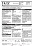
SPLIT-TYPE AIR CONDITIONERS
INSTALLATION MANUAL
Required Tools for Installation
Phillips screwdriver
PPKH[DJRQDOZUHQFK
Level
Flare tool for R410A
Scale
Gauge manifold for R410A
8WLOLW\NQLIHRUVFLVVRUV
Vacuum pump for R410A
65 mm hole saw
Charge hose for R410A
Torque wrench
Pipe cutter with reamer
Wrench (or spanner)
1. BEFORE INSTALLATION
1-1. THE FOLLOWING SHOULD ALWAYS BE OBSERVED FOR SAFETY
• Be sure to read “THE FOLLOWING SHOULD ALWAYS BE OBSERVED FOR SAFETY” before installing the air conditioner.
%HVXUHWRREVHUYHWKHZDUQLQJVDQGFDXWLRQVVSHFL¿HGKHUHDVWKH\LQFOXGHLPSRUWDQWLWHPVUHODWHGWRVDIHW\
• After reading this manual, be sure to keep it together with the OPERATING INSTRUCTIONS for future reference.
WARNING
N Do not install the unit by yourself (user).
,QFRPSOHWHLQVWDOODWLRQFRXOGFDXVH¿UHRUHOHFWULFVKRFNLQMXU\
due to the unit falling, or leakage of water. Consult the dealer
IURPZKRP\RXSXUFKDVHGWKHXQLWRUDTXDOL¿HGLQVWDOOHU
N Perform the installation securely referring to the installation manual.
,QFRPSOHWHLQVWDOODWLRQFRXOGFDXVH¿UHRUHOHFWULFVKRFNLQMXU\
due to the unit falling, or leakage of water.
N Install the unit securely in a place which can bear the
weight of the unit.
If the installation location cannot bear the weight of the unit,
WKHXQLWFRXOGIDOOFDXVLQJLQMXU\
N Perform electrical work according to the installation
manual and be sure to use an exclusive circuit. Do not
connect other electrical appliances to the circuit.
,I WKH FDSDFLW\ RI WKH SRZHU FLUFXLW LV LQVXI¿FLHQW RU WKHUH LV
LQFRPSOHWHHOHFWULFDOZRUNLWFRXOGUHVXOWLQD¿UHRUDQHOHFWULF
shock.
N Earth the unit correctly.
Do not connect the earth to a gas pipe, water pipe, lightning
rod or telephone earth. Defective earthing could cause electric
shock.
N Do not damage the wires by applying excessive pressure
with parts or screws.
'DPDJHGZLUHVFRXOGFDXVH¿UH
N Be sure to cut off the main power in case of setting up the
indoor P.C. board or wiring works.
Failure to do so could cause electric shock.
N 8VHWKHVSHFL¿HGZLUHVWRFRQQHFWWKHLQGRRUDQGRXWGRRU
XQLWVVHFXUHO\DQGDWWDFKWKHZLUHV¿UPO\WRWKHWHUPLQDO
block connecting sections so the stress of the wires is
not applied to the sections.
,QFRPSOHWHFRQQHFWLQJDQGVHFXULQJFRXOGFDXVH¿UH
&RXOGOHDGWRGHDWKVHULRXVLQMXU\HWF
N 'RQRWLQVWDOOWKHXQLWLQDSODFHZKHUHLQÀDPPDEOHJDV
may leak.
If gas leaks and accumulates in the area around the unit, it
FRXOGFDXVHDQH[SORVLRQ
N Do not use intermediate connection of the power cord or
the extension cord and do not connect many devices to
one AC outlet.
,WFRXOGFDXVHD¿UHRUDQHOHFWULFVKRFNGXHWRGHIHFWLYHFRQWDFW GHIHFWLYH LQVXODWLRQ H[FHHGLQJ WKH SHUPLVVLEOH FXUUHQW
etc.
N %HVXUHWRXVHWKHSDUWVSURYLGHGRUVSHFL¿HGSDUWVIRU
the installation work.
7KHXVHRIGHIHFWLYHSDUWVFRXOGFDXVHDQLQMXU\RUOHDNDJHRI
ZDWHUGXHWRD¿UHDQHOHFWULFVKRFNWKHXQLWIDOOLQJHWF
N When plugging the power supply plug into the outlet,
make sure that there is no dust, clogging, or loose parts
in both the outlet and the plug. Make sure that the power
supply plug is pushed completely into the outlet.
,IWKHUHLVGXVWFORJJLQJRUORRVHSDUWVRQWKHSRZHUVXSSO\
SOXJRUWKHRXWOHWLWFRXOGFDXVHHOHFWULFVKRFNRU¿UH,IORRVH
SDUWVDUHIRXQGRQWKHSRZHUVXSSO\SOXJUHSODFHLW
N Attach the electrical cover to the indoor unit and the
service panel to the outdoor unit securely.
If the electrical cover of the indoor unit and/or the service
SDQHO RI WKH RXWGRRU XQLW DUH QRW DWWDFKHG VHFXUHO\ LW FRXOG
UHVXOWLQD¿UHRUDQHOHFWULFVKRFNGXHWRGXVWZDWHUHWF
N When installing or relocating the unit, make sure that no
VXEVWDQFHRWKHUWKDQWKHVSHFL¿HGUHIULJHUDQW5$
enters the refrigerant circuit.
$Q\SUHVHQFHRIIRUHLJQVXEVWDQFHVXFKDVDLUFDQFDXVHDEQRUPDOSUHVVXUHULVHRUDQH[SORVLRQ
CAUTION
N Do not discharge the refrigerant into the atmosphere. If
refrigerant leaks during installation, ventilate the room.
,IUHIULJHUDQWFRPHVLQFRQWDFWZLWKD¿UHKDUPIXOJDVFRXOGEH
generated.
N Check that the refrigerant gas does not leak after installation has been completed.
If refrigerant gas leaks indoors, and comes into contact with
WKH ÀDPH RI D IDQ KHDWHU VSDFH KHDWHU VWRYH HWF KDUPIXO
substances will be generated.
N Use appropriate tools and piping materials for installation.
The pressure of R410A is 1.6 times more than R22. Not using appropriate tools or materials and incomplete installation
FRXOGFDXVHWKHSLSHVWREXUVWRULQMXU\
N When pumping down the refrigerant, stop the compressor
before disconnecting the refrigerant pipes.
If the refrigerant pipes are disconnected while the compressor is running and the stop valve is open, air could be drawn
LQ DQG WKH SUHVVXUH LQ WKH UHIULJHUDWLRQ F\FOH FRXOG EHFRPH
DEQRUPDOO\KLJK7KLVFRXOGFDXVHWKHSLSHVWREXUVWRULQMXU\
N When installing the unit, securely connect the refrigerant
pipes before starting the compressor.
If the compressor is started before the refrigerant pipes are
connected and when the stop valve is open, air could be
GUDZQLQDQGWKHSUHVVXUHLQWKHUHIULJHUDWLRQF\FOHFRXOGEHFRPHDEQRUPDOO\KLJK7KLVFRXOGFDXVHWKHSLSHVWREXUVWRU
LQMXU\
N )DVWHQDÀDUHQXWZLWKDWRUTXHZUHQFKDVVSHFL¿HGLQ
this manual.
,IIDVWHQHGWRRWLJKWDÀDUHQXWPD\EUHDNDIWHUDORQJSHULRG
and cause refrigerant leakage.
N The unit shall be installed in accordance with national
wiring regulations.
&RXOGOHDGWRVHULRXVLQMXU\LQSDUWLFXODUHQYLURQPHQWVZKHQRSHUDWHGLQFRUUHFWO\
If there is defect in the drainage/piping work, water could drop N Do not install the outdoor unit where small animals may
N Install an earth leakage breaker depending on the installation place.
live.
from the unit, soaking and damaging household goods.
If an earth leakage breaker is not installed, it could cause N 'RQRWWRXFKWKHDLULQOHWRUWKHDOXPLQXP¿QVRIWKH
If small animals enter and touch the electric parts inside the
electric shock.
unit, it could cause a malfunction, smoke emission, or fire.
outdoor unit.
Also, advise user to keep the area around the unit clean.
7KLVFRXOGFDXVHLQMXU\
N Perform the drainage/piping work securely according to
the installation manual.
1-2. SELECTING THE INSTALLATION LOCATION
INDOOR UNIT
:KHUHDLUÀRZLVQRWEORFNHG
• Where cool air spreads over the entire room.
• Rigid wall without vibration.
:KHUHLWLVQRWH[SRVHGWRGLUHFWVXQVKLQH
:KHUHHDVLO\GUDLQHG
$WDGLVWDQFHPRUPRUHDZD\IURP\RXU79DQGUDGLR
2SHUDWLRQRIWKHDLUFRQGLWLRQHUPD\LQWHUIHUHZLWKUDGLR
RU79UHFHSWLRQ$QDPSOL¿HUPD\EHUHTXLUHGIRUWKHDIfected device.
,QDSODFHDVIDUDZD\DVSRVVLEOHIURPÀXRUHVFHQWDQG
incandescent lights (so the infrared remote control can
RSHUDWHWKHDLUFRQGLWLRQHUQRUPDOO\
:KHUHWKHDLU¿OWHUFDQEHUHPRYHGDQGUHSODFHGHDVLO\
REMOTE CONTROLLER
:KHUHLWLVHDV\WRRSHUDWHDQGHDVLO\YLVLEOH
• Where children cannot touch it.
6HOHFWDSRVLWLRQDERXWPDERYHWKHÀRRUDQGFKHFN
WKDW VLJQDOV IURP WKH UHPRWH FRQWUROOHU DUH VXUHO\ UHFHLYHG E\ WKH LQGRRU XQLW IURP WKDW SRVLWLRQ µEHHS¶ RU
µEHHSEHHS¶UHFHLYLQJWRQHVRXQGV$IWHUWKDWDWWDFKUHmote controller holder to a pillar or wall and install wireless remote controller.
Note:
,QURRPVZKHUHLQYHUWHUW\SHÀXRUHVFHQWODPSVDUHXVHG
WKHVLJQDOIURPWKHZLUHOHVVUHPRWHFRQWUROOHUPD\QRWEH
received.
OUTDOOR UNIT
:KHUHLWLVQRWH[SRVHGWRVWURQJZLQG
:KHUHDLUÀRZLVJRRGDQGGXVWOHVV
• Where rain or direct sunlight can be avoided as much as
possible.
:KHUH QHLJKERXUV DUH QRW DQQR\HG E\ RSHUDWLRQ VRXQG
or hot air.
• Where rigid wall or support is available to prevent the
increase of operation sound or vibration.
• Where there is no risk of combustible gas leakage.
• When installing the unit at a high level, be sure to secure
the unit legs.
:KHUHLWLVDWOHDVWPDZD\IURPWKHDQWHQQDRI79VHW
RUUDGLR2SHUDWLRQRIWKHDLUFRQGLWLRQHUPD\LQWHUIHUHZLWK
radio or TV reception in areas where reception is weak.
$QDPSOL¿HUPD\EHUHTXLUHGIRUWKHDIIHFWHGGHYLFH
,QVWDOOWKHXQLWKRUL]RQWDOO\
3OHDVH LQVWDOO LW LQ DQ DUHD QRW DIIHFWHG E\ VQRZIDOO RU
EORZLQJVQRZ,QDUHDVZLWKKHDY\VQRZSOHDVHLQVWDOOD
FDQRS\DSHGHVWDODQGRUVRPHEDIÀHERDUGV
Note:
It is advisable to make a piping loop near outdoor unit so as
to reduce vibration transmitted from there.
Note:
When operating the air conditioner in low outside temperature, be sure to follow the instructions described below.
• Never install the outdoor unit in a place where its air
LQOHWRXWOHWVLGHPD\EHH[SRVHGGLUHFWO\WRZLQG
7R SUHYHQW H[SRVXUH WR ZLQG LQVWDOO WKH RXWGRRU XQLW
with its air inlet side facing the wall.
• 7RSUHYHQWH[SRVXUHWRZLQGLWLVUHFRPPHQGHGWRLQVWDOO
DEDIÀHERDUGRQWKHDLURXWOHWVLGHRIWKHRXWGRRUXQLW
Avoid the following places for installation where air conditioner trouble is liable to occur.
:KHUHÀDPPDEOHJDVFRXOGOHDN
• Where there is much machine oil.
6DOW\SODFHVVXFKDVWKHVHDVLGH
:KHUHVXO¿GHJDVLVJHQHUDWHGVXFKDVDKRWVSULQJ
:KHUHWKHUHLVKLJKIUHTXHQF\RUZLUHOHVVHTXLSPHQW
1-3. SPECIFICATIONS
3RZHUVXSSO\
Model
Indoor unit
MSZ-FB50VA
Outdoor unit
MUZ-FB50VA
MUZ-FB50VAH
:LUHVSHFL¿FDWLRQV
Rated
Voltage
)UHTXHQF\
Breaker
FDSDFLW\
3RZHUVXSSO\
230 V
50 Hz
16 A
3-core
2.0 mm2
*1 Connect to the power switch which has a gap of 3 mm or
more when open to interrupt the source power phase. (When
the power switch is shut off, it must interrupt all phases.)
*2 8VH ZLUHV LQ FRQIRUPLW\ ZLWK GHVLJQ ,(& 7KH XQLW
shall be installed in accordance with national wiring regulations.
*3 Never use pipes with thickness less than specified. The
SUHVVXUHUHVLVWDQFHZLOOEHLQVXI¿FLHQW
Pipe size
(thickness *3, *4)
Indoor/outdoor
Gas / Liquid
connecting wire
4-core
ø12.7 / 6.35 mm
1.0 mm2
(0.8 mm)
Pipe length and height difference
30 m
0D[SLSHOHQJWK
0D[KHLJKWGLIIHUHQFH
15 m
0D[QXPEHURIEHQGV
10
Refrigerant adjustment A *7
30 g/m
Insulation thickness *8, *9
8 mm
8VHDFRSSHUSLSHRUDFRSSHUDOOR\VHDPOHVVSLSH
Additional refrigerant = A × (pipe length (m) - 7)
*5 Be careful not to crush or bend the pipe during pipe bending. *8 Insulation material : Heat resisting foam plastic 0.045
*6 Refrigerant pipe bending radius must be 100 mm or more.
VSHFL¿FJUDYLW\
,I SLSH OHQJWK H[FHHGV P DGGLWLRQDO UHIULJHUDQW 5$ %HVXUHWRXVHWKHLQVXODWLRQRIVSHFL¿HGWKLFNQHVV([FHVVLYHWKLFNQHVVPD\FDXVHLQFRUUHFWLQVWDOODWLRQRIWKHLQGRRU
charge is required. (No additional charge is required for
XQLWDQGLQVXI¿FLHQWWKLFNQHVVPD\FDXVHGHZGULSSDJH
pipe length less than 7 m.)
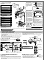
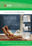
1-4. INSTALLATION DIAGRAM
,QVWDOODWLRQSODWH¿[LQJVFUHZ
4 × 25 mm
5
(3) Remote controller holder
84 mm
or mo
re
(4)
)L[LQJVFUHZIRU × 16 mm
(Black)
2
(5)
(6)
(7)
(8)
(9)
%DWWHU\$$$IRU
Wireless remote controller
Felt tape (For left or left-rear piping)
3ODVPDDQWLDOOHUJ\HQ]\PH¿OWHU
3ODVPDGHRGRUL]LQJ¿OWHU
2
1
1
1
1
$IWHUWKHOHDNWHVWDSSO\
LQVXODWLQJPDWHULDOWLJKWO\
so that there is no gap.
When the piping is to be
attached to a wall containing metals (tin plated) or
metal netting, use a chemiFDOO\WUHDWHGZRRGHQSLHFH
20 mm or thicker between
the wall and the piping or
wrap 7 to 8 turns of insulaWLRQYLQ\OWDSHDURXQGWKH
piping.
7RXVHH[LVWLQJSLSLQJSHUform COOL operation for
30 minutes and pump down
before removing the old air
FRQGLWLRQHU5HPDNHÀDUH
according to the dimension
for new refrigerant.
7 mm or more
1
2
PARTS TO BE PROVIDED
AT YOUR SITE
(A)
(B)
(C)
(D)
(E)
(F)
(G)
(H)
Indoor/outdoor unit connecting wire* 1
([WHQVLRQSLSH
1
Wall hole sleeve
1
Wall hole cover
1
3LSH¿[LQJEDQG
2 to 5
)L[LQJVFUHZIRU(îPP
2 to 5
Piping tape
1
3XWW\
1
Drain hose
(I) (or soft PVC hose, 15 mm inner
diameter or hard PVC pipe VP16)
1
(J) Refrigeration oil
(K) 3RZHUVXSSO\FRUG
1
1
3LSH¿[LQJEDQG
(E)
)L[LQJVFUHZ
(F)
<Outdoor unit>
(10) 'UDLQVRFNHW9$W\SHRQO\
(11) 'UDLQFDS9$W\SHRQO\
)L[WKHSLSHWRZDOO
ZLWKSLSH¿[LQJ
band (E).
Cut off the
H[WUDOHQJWK
84 mm
or mo
re
1
Seal the wall hole
JDSZLWKSXWW\+
500 mm
or more
mme
10r0mor
o
1 0
or0m
m
orem
r
o
mm
500ore
m
* Note:
Place indoor/outdoor unit connecting wire (A)
DQGSRZHUVXSSO\FRUG.DWOHDVWPDZD\
from the TV antenna wire.
(11)
3 0
or5m
m
orem
8QLWVVKRXOGEHLQVWDOOHGE\OLFHQVHGFRQWUDFWRU $SSHDUDQFHRIWKHRXWGRRUXQLWPD\GLIIHUIURPVRPH
models.
according to local code requirements.
(10)
(I)
Outdoor unit installation
840 mm
169
mm
500 mm
Air inlet
360 mm
(2)
1
Wall hole cover (D)
Be sure to use wall hole
Indoor unit
sleeve (C) to prevent
indoor/outdoor connecting
wire (A) from contacting
Wall hole
metal parts in the wall and sleeve (C)
WRSUHYHQWGDPDJHE\
rodents in case the wall is
hollow.
392 mm
330 mm
(1) Installation plate
60 mm or more/
142.5 mm or more for
left and left back piping
(using spacer)
ACCESSORIES
Check the following parts before installation.
<Indoor unit>
Air outlet
4-10 mm × 21 mm slot
40 mm
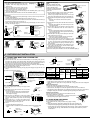
Drain piping for outdoor unit
9$W\SHRQO\!
• Provide drain piping before indoor and
outdoor piping connection.
• Connect drain hose (I) I.D.15 mm as
shown in the illustration.
• Choose one hole for draining, and
install drain socket (10). Close the remaining two holes with drain cap (11).
• Make sure to provide drain piping with
DGRZQKLOOJUDGHIRUHDV\GUDLQÀRZ
Note:
Do not use drain socket (10) in cold
UHJLRQV'UDLQPD\IUHH]HDQGPDNHWKH
fan stop.
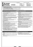
IMPORTANT NOTES
7RFRPSO\ZLWKWKHUHTXLUHPHQWVRI$XVWUDOLDQVWDQGDUG$66$$
wiring rules, the electrical wiring required between the indoor and outGRRUXQLWVPXVWEHLQVWDOOHGE\DOLFHQFHGHOHFWULFDOFRQWUDFWRU
2. INDOOR UNIT INSTALLATION
2-1. FIXING OF INSTALLATION PLATE
)LQGDVWUXFWXUDOPDWHULDOVXFKDVDVWXGLQWKHZDOODQG¿[LQVWDOODWLRQSODWHKRUL]RQWDOO\ZLWK¿[LQJVFUHZV
7R SUHYHQW LQVWDOODWLRQ SODWH IURP YLEUDWLQJ EH VXUH WR LQVWDOO WKH ¿[LQJ VFUHZV LQ
WKH KROHV LQGLFDWHG LQ WKH LOOXVWUDWLRQ )RU DGGHG VXSSRUW ¿[LQJ VFUHZV PD\ DOVR EH
installed in other holes.
• When bolts recessed in the concrete wall are to be utilized, secure installation plate (1)
using 11 × 20 · 11 × 26 oval hole (450 mm pitch).
• If the recessed bolt is too long, change it for a shorter one available in the market.
VA clamp
1) Determine the wall hole position.
2) Drill a ø 65 mm hole. The outdoor side should be
5 to 7 mm lower than the indoor side.
3) Insert wall hole sleeve (C).
Ceiling
Bind the line to the center hole.
)L[LQJ
screw
Terminal block
Wall
2-2. WALL HOLE DRILLING
Installation plate (1)
)LUPO\WLJKWHQWKHWHUPLQDOVFUHZVWRSUHYHQWWKHPIURPORRVHQLQJ$IWHUWLJKWHQLQJSXOO
WKHZLUHVOLJKWO\WRFRQ¿UPWKDWWKH\GRQRWPRYH
6) Secure indoor/outdoor unit connecting wire (A) and the earth wire with the VA clamp.
1HYHUIDLOWRKRRNWKHULJKWFODZRIWKH9$FODPS$WWDFKWKH9$FODPSVHFXUHO\
5HLQVWDOOFRUQHUER[
15 mm
Outdoor
side
25 mm
Corner
ER[
60 mm or more
142.5 mm or more for left and left
back piping (using spacer)
Lead wire
Level
Indoor/outdoor unit
connecting wire (A)
84 mm or
more
84 mm or
more
100 mm
Wall
Wall
• Make earth wire a little longer than
others. (More than 55 mm)
)RUIXWXUHVHUYLFLQJJLYHH[WUDOHQJWK
to the connecting wires.
Indoor terminal block
Earth wire
JUHHQ\HOORZ
Indoor/outdoor unit
connecting wire (A)
)L[LQJVFUHZ
Align the plumb
line with the
mark .
Insert
the
scale. *
Align the
scale with
the line. *
Center of
ø 65 mm hole
Plumb
* Same for left hole.
2-3. CONNECTING WIRES FOR INDOOR UNIT
You can connect indoor/outdoor lead wire without removing the front panel.
5HPRYHFRUQHUER[
2) Remove VA clamp.
3URFHVVWKHHQGRIHDUWKZLUHDQGFRQQHFWLWWRWKHHDUWKWHUPLQDORIHOHFWULFDOSDUWVER[
3URFHVVWKHHQGRILQGRRURXWGRRUXQLWFRQQHFWLQJZLUH$DQG¿[LWWRWHUPLQDOEORFN
%HFDUHIXOQRWWRPDNHPLVZLULQJ)L[WKHZLUHWRWKHWHUPLQDOEORFNVHFXUHO\VRWKDWQR
SDUWRILWVFRUHLVDSSHDUHGDQGQRH[WHUQDOIRUFHLVFRQYH\HGWRWKHFRQQHFWLQJVHFtion of the terminal block.
Outdoor terminal block
2-4. PIPE FORMING AND DRAIN PIPING
Pipe Forming
• Place the drain hose below the refrigerant piping.
• Make sure that the drain hose is not heaved or snaked.
'RQRWSXOOWKHKRVHZKHQDSSO\LQJWKHWDSH
• When the drain hose passes the room, be sure to wrap
insulation material (obtainable at a store) around it.
Liquid pipe
Gas pipe
Indoor/outdoor unit
connecting wire (A)
Felt tape (7)
Piping tape (G)
Rear, right, or downward piping
Cut off in case of
1) Put the refrigerant piping and the drain hose
right piping.
WRJHWKHU WKHQ ILUPO\ DSSO\ SLSLQJ WDSH *
from the end.
Cut off in case of
2) Insert the piping and the drain hose into the
downward piping.
wall hole sleeve (C), and hook the upper part
of the indoor unit on the installation plate (1).
&KHFNLIWKHLQGRRUXQLWLVKRRNHGVHFXUHO\RQWKHLQVWDOODWLRQSODWHE\PRYLQJ
the unit to left and right.
4) Thrust the lower part of the indoor unit into the installation plate (1).
Drain Piping
,IWKHH[WHQVLRQGUDLQKRVHKDVWRSDVVWKURXJKDURRPEHVXUHWRZUDSLWZLWKFRPPHUFLDOO\VROGLQVXODWLRQ
7KHGUDLQKRVHVKRXOGSRLQWGRZQZDUGIRUHDV\GUDLQÀRZ)LJ
• If the drain hose provided with the indoor unit is too short, connect it with drain hose (I)
WKDWVKRXOGEHSURYLGHGDW\RXUVLWH)LJ
:KHQFRQQHFWLQJWKHGUDLQKRVHWRWKHKDUGYLQ\OFKORULGHSLSHEHVXUHWRLQVHUWLW
VHFXUHO\LQWRWKHSLSH)LJ
Drain hose
Drain
hose
Downward
slope
+DUGYLQ\OFKORULGH
pipe I.D. 30 mm
70 cm or
more
Soft hose
I.D. 15 mm
Insert
VHFXUHO\
Different
diameter joint
Fig. 1
Fig. 2
Fig. 3
Do not make drain piping as shown below.
Accumulated
drain water
Do not raise
Tip of drain
hose dipped
in water
Air
Water
leakage
Water
leakage
Waving
Water
leakage
At least
50 mm
gap
Ditch
Left or left-rear piping
Note:
Be sure to reattach the drain
hose and the drain cap in case
of left or left-rear piping.
Otherwise, it could cause drops
of water to drip down from the
drain hose.
Cut off in case of left
piping.
Piping tape (G)
Felt tape (7)
Drain cap
Drain cap
1) Put the refrigerant piping and the drain hose together,
WKHQ¿UPO\DSSO\IHOWWDSHIURPWKHHQG
Felt tape (7) overlap width should be 1/3 the tape
width. Use a bandage stopper at the end of felt tape (7).
2) Pull out the drain cap at the rear right of the indoor unit.
Fig. 1
(Fig. 1)
+ROGWKHFRQYH[VHFWLRQDWWKHHQGDQGSXOOWKH
drain cap.
3) Pull out the drain hose at the rear left of the indoor unit.
(Fig. 2)
Drain hose
+ROGWKHFODZPDUNHGE\WKHDUURZVDQGSXOORXWWKH
Fig. 2
drain hose forward.
4) Put the drain cap into the section to which the drain
hose is to be attached at the rear of the indoor unit.
(Fig. 3)
• Insert not sharp-edged tools such as screwdrivers
Drain cap
into the hole at the end of the cap and insert the cap
IXOO\LQWRWKHGUDLQSDQ
Fig. 3
,QVHUWWKHGUDLQKRVHIXOO\LQWRWKHGUDLQSDQDWWKHUHDU
Drain hose
right of the indoor unit. (Fig. 4)
&KHFNLIWKHKRVHLVKRRNHGVHFXUHO\WRWKHSURMHFtion of its inserting part at the drain pan.
Fig. 4
6) Insert the drain hose into wall hole sleeve (C), and
hook the upper part of indoor unit on installation plate
7KHQPRYHWKHLQGRRUXQLWFRPSOHWHO\WRWKHOHIWLQ
order to make placing the piping in the back space of
the unit easier.
&XWRXWDSLHFHRIFDUGERDUGIURPWKHVKLSSLQJER[UROO
Fig. 5
it up, hook it onto the back rib, and use it as a spacer
to lift the indoor unit. (Fig. 5)
&RQQHFWWKHUHIULJHUDQWSLSLQJZLWKWKHH[WHQVLRQSLSH%
9) Thrust the lower part of the indoor unit into the installation plate (1).
3. OUTDOOR UNIT INSTALLATION
3-1. CONNECTING WIRES FOR OUTDOOR UNIT
1) Open the service panel.
2) Loosen terminal screw, and connect indoor/outdoor unit connecting wire (A) from
WKHLQGRRUXQLWFRUUHFWO\RQWKHWHUPLQDOEORFN%HFDUHIXOQRWWRPDNHPLVZLULQJ)L[
WKHZLUHWRWKHWHUPLQDOEORFNVHFXUHO\VRWKDWQRSDUWRILWVFRUHLVDSSHDUHGDQGQR
H[WHUQDOIRUFHLVFRQYH\HGWRWKHFRQQHFWLQJVHFWLRQRIWKHWHUPLQDOEORFN
)LUPO\WLJKWHQWKHWHUPLQDOVFUHZVWRSUHYHQWWKHPIURPORRVHQLQJ$IWHUWLJKWHQLQJ
SXOOWKHZLUHVOLJKWO\WRFRQ¿UPWKDWWKH\GRQRWPRYH
&RQQHFWSRZHUVXSSO\FRUG.
)L[LQGRRURXWGRRUXQLWFRQQHFWLQJZLUH$DQGSRZHUVXSSO\FRUG.ZLWKWKHFRUG
clamp.
&ORVHWKHVHUYLFHSDQHOVHFXUHO\
Terminal block
15 mm
• Make earth wire a little longer
than others. (More than 60 mm)
)RU IXWXUH VHUYLFLQJ JLYH H[WUD
length to the connecting wires.
35 mm
Indoor/outdoor unit
connecting wire (A)
3RZHUVXSSO\FRUG.
3RZHUVXSSO\
cord (K)
Cord clamp
Lead wire
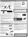
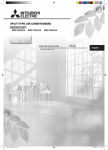
3-2. FLARING WORK
&XW WKH FRSSHU SLSH FRUUHFWO\ ZLWK SLSH FXWWHU
Copper
(Fig. 1, 2)
pipe
&RPSOHWHO\UHPRYHDOOEXUUVIURPWKHFXWFURVVVHFtion of pipe. (Fig. 3)
Fig. 1
• Put the end of the copper pipe to downward direcWLRQDV\RXUHPRYHEXUUVLQRUGHUWRDYRLGWROHW
burrs drop in the piping.
No good
Good
3) Remove flare nuts attached to indoor and outdoor
units, then put them on pipe having completed burr
removal. (Not possible to put them on after flaring
work.)
)ODULQJ ZRUN )LJ )LUPO\ KROG FRSSHU SLSH LQ
Tilted Uneven Burred
the dimension shown in the table. Select A mm from
Fig. 2
WKHWDEOHDFFRUGLQJWRWKHWRRO\RXXVH
5) Check
&RPSDUHWKHÀDUHGZRUNZLWK)LJ
,IÀDUHLVQRWHGWREHGHIHFWLYHFXWRIIWKHÀDUHGVHFWLRQDQGGRÀDULQJZRUN
again.
Flaring tool
Burr
Copper pipe
Spare reamer
Pipe cutter
&OXWFKW\SH
Fig. 3
:LQJQXWW\SH
Fig. 4
Smooth all
around
Inside is shinLQJZLWKRXWDQ\
scratches.
Copper pipe
Die
Flare nut
Pipe diameter
(mm)
ø 6.35 (1/4”)
ø 9.52 (3/8”)
ø12.7 (1/2”)
ø15.88 (5/8”)
Fig. 5
Even length
all around
A (mm)
Nut &OXWFKW\SH &OXWFKW\SH Wing nut
(mm)
tool
tool
W\SHWRRO
for R410A
for R22
for R22
17
1.5 to 2.0
22
0 to 0.5
1.0 to 1.5
26
2.0 to 2.5
29
Fig. 6
Tightening torque
N•m
kgf•cm
13.7 to 17.7
34.3 to 41.2
49.0 to 56.4
73.5 to 78.4
140 to 180
350 to 420
500 to 575
750 to 800
3-3. PIPE CONNECTION
)DVWHQÀDUHQXWZLWKDWRUTXHZUHQFKDVVSHFL¿HGLQWKHWDEOH
:KHQ IDVWHQHG WRR WLJKW ÀDUH QXW PD\ EUDNH DIWHU D ORQJ SHULRG DQG FDXVH UHIULJHUDQW
leakage.
Indoor unit connection
Connect both liquid and gas pipings to indoor unit.
$SSO\DWKLQFRDWRIUHIULJHUDWLRQRLO-RQWKHVHDWVXUIDFHRISLSH
)RUFRQQHFWLRQ¿UVWDOLJQWKHFHQWHUWKHQWLJKWHQWKH¿UVWWRWXUQVRIÀDUHQXW
• Use tightening torque table below as a guideline for indoor unit side union joint section,
DQGWLJKWHQXVLQJWZRZUHQFKHV([FHVVLYHWLJKWHQLQJGDPDJHVWKHÀDUHVHFWLRQ
Outdoor unit connection
Connect pipes to stop valve pipe joint of the outdoor unit in the
same manner applied for indoor unit.
• For tightening, use a torque wrench or spanner and use the
same tightening torque applied for indoor unit.
3-4. INSULATION AND TAPING
1) Cover piping joints with pipe cover.
)RU RXWGRRU XQLW VLGH VXUHO\ LQVXODWH HYHU\ SLSLQJ LQFOXGLQJ
valves.
8VLQJSLSLQJWDSH*DSSO\WDSLQJVWDUWLQJIURPWKHHQWU\RIRXWGRRUXQLW
• Stop the end of piping tape (G) with tape (with adhesive agent attached).
• When piping have to be arranged through above ceiling, closet or where the temperaWXUHDQGKXPLGLW\DUHKLJKZLQGDGGLWLRQDOFRPPHUFLDOO\VROGLQVXODWLRQWRSUHYHQW
condensation.
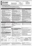
4. PURGING PROCEDURES, LEAK TEST, AND TEST RUN
4-1. PURGING PROCEDURES AND LEAK TEST
1) Remove service port cap of stop valve on the side of the outdoor unit gas pipe. (The
VWRSYDOYHZLOOQRWZRUNLQLWVLQLWLDOVWDWHIUHVKRXWRIWKHIDFWRU\WRWDOO\FORVHGZLWKFDS
on.)
2) Connect gauge manifold valve and vacuum pump to service port of stop valve on the
gas pipe side of the outdoor unit.
*4 to 5 turns
Stop valve cap
(Torque 19.6 to
29.4 N•m, 200
WRNJIƒFP
*Close
*Open
–0.101 MPa
(–760 mmHg)
Compound pressure gauge
(for R410A)
Pressure gauge
(for R410A)
Stop valve
for LIQUID
Gauge manifold valve
(for R410A)
Handle
Low
Handle High
+H[DJRQDOZUHQFK
Charge hose
(for R410A)
Stop valve for
GAS
Service port cap
(Torque 13.7 to
17.7 N•m, 140 to
180 kgf•cm)
Adapter for preventing the back
ÀRZ
Vacuum pump (or the vacuum
pump with the function to
SUHYHQWWKHEDFNÀRZ
Precautions when using the control valve When attaching the control valve
WRWKHVHUYLFHSRUWYDOYHFRUHPD\
GHIRUPRUORRVHQLIH[FHVVSUHVVXUH
LVDSSOLHG7KLVPD\FDXVHJDVOHDN
Service port
A
Control valve
Open
Charge hose
Close
%RG\
When attaching the control valve to
the service port, make sure that the
valve core is in closed position, and
then tighten part A. Do not tighten
SDUW$RUWXUQWKHERG\ZKHQYDOYH
core is in open position.
3) Run the vacuum pump. (Vacuumize for more than 15 minutes.)
4) Check the vacuum with gauge manifold valve, then close gauge manifold valve, and
stop the vacuum pump.
5) Leave as it is for one or two minutes. Make sure pointer gauge manifold valve remains
LQWKHVDPHSRVLWLRQ&RQ¿UPWKDWSUHVVXUHJDXJHVKRZV±03D>*DXJH@±
mmHg).
5HPRYHJDXJHPDQLIROGYDOYHTXLFNO\IURPVHUYLFHSRUWRIVWRSYDOYH
$IWHUUHIULJHUDQWSLSHVDUHFRQQHFWHGDQGHYDFXDWHGIXOO\RSHQDOOVWRSYDOYHVRQERWK
VLGHVRIJDVSLSHDQGOLTXLGSLSH2SHUDWLQJZLWKRXWIXOO\RSHQLQJORZHUVWKHSHUIRUPance and this causes trouble.
8) Refer to 1-3., and charge the prescribed amount of refrigerant if needed. Be sure to
FKDUJH VORZO\ ZLWK OLTXLG UHIULJHUDQW 2WKHUZLVH FRPSRVLWLRQ RI WKH UHIULJHUDQW LQ WKH
V\VWHPPD\EHFKDQJHGDQGDIIHFWSHUIRUPDQFHRIWKHDLUFRQGLWLRQHU
9) Tighten cap of service port to obtain the initial status.
10) Leak test
mode (set temperature 24ºC) will start.
3) To stop operation, press the E.O. SW several times
until all LED lamps turn off. Refer to operating instructions for details.
Checking the remote (infrared) signal reception
Press the ON/OFF button on the remote controller (6)
and check that an electronic sound is heard from the
indoor unit. Press the ON/OFF button again to turn the air
conditioner off.
• Once the compressor stops, the restart preventive device operates so the compressor will not operate for 3
minutes to protect the air conditioner.
(PHUJHQF\
operation switch
(E.O. SW)
4-3. AUTO RESTART FUNCTION
7KLVSURGXFWLVHTXLSSHGZLWKDQDXWRUHVWDUWIXQFWLRQ:KHQWKHSRZHUVXSSO\LVVWRSSHG
GXULQJRSHUDWLRQVXFKDVGXULQJEODFNRXWVWKHIXQFWLRQDXWRPDWLFDOO\VWDUWVRSHUDWLRQLQ
WKHSUHYLRXVVHWWLQJRQFHWKHSRZHUVXSSO\LVUHVXPHG5HIHUWRWKHRSHUDWLQJLQVWUXFtions for details.)
Caution:
• After test run or remote signal reception check, turn off the unit with the E.O. SW or
WKHUHPRWHFRQWUROOHUEHIRUHWXUQLQJRIIWKHSRZHUVXSSO\1RWGRLQJVRZLOOFDXVHWKH
XQLWWRVWDUWRSHUDWLRQDXWRPDWLFDOO\ZKHQSRZHUVXSSO\LVUHVXPHG
To the user
$IWHULQVWDOOLQJWKHXQLWPDNHVXUHWRH[SODLQWKHXVHUDERXWDXWRUHVWDUWIXQFWLRQ
,I DXWR UHVWDUW IXQFWLRQ LV XQQHFHVVDU\ LW FDQ EH GHDFWLYDWHG &RQVXOW WKH VHUYLFH
representative to deactivate the function. Refer to the service manual for details.
4-4. REMOTE CONTROLLER SETTING
Set the slide switch of the remote controller according to the installed position of the
LQGRRUXQLW,IWKHVZLWFKLVQRWVHWFRUUHFWO\WKHDLUFRQGLWLRQHUPD\QRWIXQFWLRQSURSHUO\
Installation position:
Left: Distance to objects (wall, cabinet, etc.) is less
than 50 cm to the left
Center: Distance to objects (wall, cabinet, etc.) is
more than 50 cm to the left and right
Right: Distance to objects (wall, cabinet, etc.) is less
than 50 cm to the right
(Left) (Center)(Right)
1) Remove the front lid.
2) Set the slide switch according to the installed position of the indoor unit.
3) Insert two (AAA) batteries.
SLIDE SWITCH
4) Reattach the front lid.
3UHVVWKH5(6(7EXWWRQJHQWO\XVLQJDWKLQVWLFN
RESET
Installation position
Left
Center
Right
button
Slide switch
Remote controller
GLVSOD\
4-2. TEST RUN
,QVHUWSRZHUVXSSO\SOXJLQWRWKHSRZHURXWOHWDQGRUWXUQRQWKHEUHDNHU&KHFNWKDW 4-5. EXPLANATION TO THE USER
DOO/('ODPSVDUHQRWOLW,IWKH\DUHEOLQNLQJFKHFNWKDWWKHKRUL]RQWDOYDQHLVLQVWDOOHG 8VLQJWKH23(5$7,1*,16758&7,216H[SODLQWRWKHXVHUKRZWRXVHWKHDLUFRQGLWLRQHUKRZWRXVHWKHUHPRWHFRQWUROOHUKRZWRUHPRYHWKHDLU¿OWHUVKRZWRUHPRYH
FRUUHFWO\5HIHUWRRSHUDWLQJLQVWUXFWLRQVIRUGHWDLOV
or put the remote controller in the remote controller holder, how to clean, precautions
2) Press the E.O. SW once for COOL, and twice for HEAT operation. Test run will be perfor operation, etc.)
IRUPHGIRUPLQXWHV,IWKHRSHUDWLRQLQGLFDWRUEOLQNVHYHU\VHFRQGVLQVSHFWWKH
LQGRRURXWGRRU XQLW FRQQHFWLQJ ZLUH $ IRU PLVZLULQJ $IWHU WKH WHVW UXQ HPHUJHQF\ 5HFRPPHQGWKHXVHUWRUHDGWKH23(5$7,1*,16758&7,216FDUHIXOO\
5. RELOCATION AND MAINTENANCE
5-1. REMOVING AND INSTALLING THE PANEL ASSEMBLY
5-3. PUMPING DOWN
:KHQUHORFDWLQJRUGLVSRVLQJRIWKHDLUFRQGLWLRQHUSXPSGRZQWKHV\VWHPIROORZLQJWKH
procedure below so that no refrigerant is released into the atmosphere.
1) Connect the gauge manifold valve to the service port of the stop valve on the gas pipe
side of the outdoor unit.
)XOO\FORVHWKHVWRSYDOYHRQWKHOLTXLGSLSHVLGHRIWKHRXWGRRUXQLW
&ORVHWKHVWRSYDOYHRQWKHJDVSLSHVLGHRIWKHRXWGRRUXQLWDOPRVWFRPSOHWHO\VRWKDW
LW FDQ EH HDVLO\ FORVHG IXOO\ ZKHQ WKH SUHVVXUH JDXJH VKRZV 03D >*DXJH@ NJI
cm2).
6WDUWWKHHPHUJHQF\&22/RSHUDWLRQ
To start the HPHUJHQF\ RSHUDWLRQ LQ &22/ PRGH GLVFRQQHFW WKH SRZHU VXSSO\ SOXJ
DQGRU WXUQ RII WKH EUHDNHU $IWHU VHFRQGV FRQQHFW WKH SRZHU VXSSO\ SOXJ DQGRU
turn on the breaker, and then press the E.O. SW once. (The HPHUJHQF\ &22/
operationFDQEHSHUIRUPHGFRQWLQXRXVO\IRUXSWRPLQXWHV
)XOO\FORVHWKHVWRSYDOYHRQWKHJDVSLSHVLGHRIWKHRXWGRRUXQLWZKHQWKHSUHVVXUH
JDXJHVKRZVWR03D>*DXJH@DSSUR[WRNJIFP2).
6) Stop the HPHUJHQF\&22/RSHUDWLRQ.
Press the E.O. SW twice to stop the operation.
Removal procedure
5HPRYHWKHVFUHZVZKLFK¿[WKHSDQHODVVHPEO\
5HPRYH WKH SDQHO DVVHPEO\ %H VXUH WR UHPRYH
LWVERWWRPHQG¿UVW
Installation procedure
,QVWDOO WKH SDQHO DVVHPEO\ IROORZLQJ WKH UHPRYDO
procedure in reverse.
%HVXUHWRSUHVVWKHSRVLWLRQVDVLQGLFDWHGE\WKH
DUURZVLQRUGHUWRDWWDFKWKHDVVHPEO\FRPSOHWHO\
to the unit.
5-2. REMOVING THE INDOOR UNIT
Remove the bottom of the indoor unit from the installation plate.
When releasing the corner part, release both left and right bottom
corner part of indoor unit and pull it downward and forward as
VKRZQLQWKH¿JXUHRQWKHULJKW
If the above method cannot be used
5HPRYHWKHIURQWSDQHO7KHQLQVHUWKH[DJRQDOZUHQFKHVLQWRWKH
square holes on the left and right
sides of the unit and push them
XSDVVKRZQLQWKHIROORZLQJ¿Jure. The bottom of the indoor unit
lowers and releases the hooks.
Push
Lower
Square hole
HEAD OFFICE: TOKYO BLDG., 2-7-3, MARUNOUCHI, CHIYODA-KU, TOKYO
100-8310, JAPAN