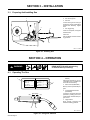
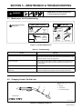
1
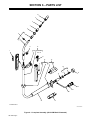
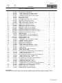
OM-1029A November 1993 Eff. w/Style Number KD-34 Processes MIG (GMAW) Welding Description Air-Cooled Gun GA-21C And GA-21CM Visit our website at www.MillerWelds.com From Miller to You Thank you and congratulations on choosing Miller. Now you can get the job done and get it done right. We know you don’t have time to do it any other way. That’s why when Niels Miller first started building arc welders in 1929, he made sure his products offered long-lasting value and superior quality. Like you, his customers couldn’t afford anything less. Miller products had to be more than the best they could be. They had to be the best you could buy. Today, the people that build and sell Miller products continue the tradition. They’re just as committed to providing equipment and service that meets the high standards of quality and value established in 1929. This Owner’s Manual is designed to help you get the most out of your Miller products. Please take time to read the Safety precautions. They will help you protect yourself against potential hazards on the worksite. We’ve made installation and operation quick and easy. With Miller you can count on years of reliable service with proper maintenance. And if for some reason the unit needs repair, there’s a Troubleshooting section that will help you Miller is the first welding figure out what the problem is. The parts list equipment manufacturer in will then help you to decide which exact part the U.S.A. to be registered to the ISO 9001 Quality System you may need to fix the problem. Warranty and Standard. service information for your particular model are also provided. Miller Electric manufactures a full line of welders and welding related equipment. For information on other quality Miller products, contact your local Miller distributor to receive the latest full line catalog or individual catalog sheets. To locate your nearest distributor or service agency call 1-800-4-A-Miller, or visit us at www.MillerWelds.com on the web. Working as hard as you do – every power source from Miller is backed by the most hassle-free warranty in the business. Miller offers a Technical Manual which provides more detailed service and parts information for your unit. To obtain a Technical Manual, contact your local distributor. Your distributor can also supply you with Welding Process Manuals such as SMAW, GTAW, GMAW, and GMAW-P. SAFETY PRECAUTIONS FOR GMAW GUNS WARNING GMAW WELDING can be hazardous. PROTECT YOURSELF AND OTHERS FROM POSSIBLE SERIOUS INJURY OR DEATH. KEEP CHILDREN AWAY. PACEMAKER WEARERS KEEP AWAY UNTIL CONSULTING YOUR DOCTOR. In welding, as in most jobs, exposure to certain hazards occurs. Welding is safe when precautions are taken. The safety information given below is only a summary of the more complete safety information found in the wire feeder and welding power source Owner’s Manuals. Read and follow all safety precautions. HAVE ALL INSTALLATION, OPERATION, MAINTENANCE, AND REPAIR WORK PERFORMED ONLY BY QUALIFIED PEOPLE. ELECTRIC SHOCK can kill. 1. 2. 3. 4. Always wear dry insulating gloves. Insulate yourself from work and ground. Do not touch live electrode or electrical parts. Repair or replace worn, damaged, or cracked gun or cable insulation. 5. Turn off welding power source before changing contact tip or gun parts. 6. Keep all covers and handle securely in place. FUMES AND GASES can be hazardous to your health. 1. Keep your head out of the fumes. 2. Ventilate area, or use breathing device. 3. Read Material Safety Data Sheets (MSDSs) and manufacturer’s instructions for material used. WELDING can cause fire or explosion. 1. Do not weld near flammable material. 2. Do not weld on closed containers. 3. Watch for fire; keep extinguisher nearby. ARC RAYS can burn eyes and skin. 1. Wear welding helmet with correct shade of filter. 2. Wear correct eye and body protection. 3. Cover exposed skin with spatter-resistant clothing. HOT SURFACES can burn skin. 1. Allow gun to cool before touching. 2. Do not touch hot metal. 3. Protect hot metal from contact by others. NOISE can damage hearing; SOME APPLICATIONS, SUCH AS PULSING, are noisy. 1. Check for noise level limits exceeding those specified by OSHA. 2. Use approved ear plugs or ear muffs if noise level is high. 3. Warn others nearby about noise hazard. WELDING WIRE can cause puncture wounds. 1. Keep hands and body away from gun tip when trigger is pressed. EMF INFORMATION NOTE Considerations About Welding And The Effects Of Low Frequency Electric And Magnetic Fields The following is a quotation from the General Conclusions Section of the U.S. Congress, Office of Technology Assessment, Biological Effects of Power Frequency Electric & Magnetic Fields – Background Paper, OTA-BP-E-53 (Washington, DC: U.S. Government Printing Office, May 1989): “. . . there is now a very large volume of scientific findings based on experiments at the cellular level and from studies with animals and people which clearly establish that low frequency magnetic fields can interact with, and produce changes in, biological systems. While most of this work is of very high quality, the results are complex. Current scientific understanding does not yet allow us to interpret the evidence in a single coherent framework. Even more frustrating, it does not yet allow us to draw definite conclusions about questions of possible risk or to offer clear science-based advice on strategies to minimize or avoid potential risks.” To reduce magnetic fields in the workplace, use the following procedures: 1. Keep cables close together by twisting or taping them. 2. Arrange cables to one side and away from the operator. 3. Do not coil or drape cables around the body. 4. Keep welding power source and cables as far away as practical. 5. Connect work clamp to workpiece as close to the weld as possible. About Pacemakers: The above procedures are among those also normally recommended for pacemaker wearers. Consult your doctor for complete information. mod10.1 4/93 sr7 7/93 SECTION 1 – SAFETY INFORMATION mod1.1 8/92 Read all safety messages throughout this manual. Obey all safety messages to avoid injury. Learn the meaning of WARNING and CAUTION. 1 2 2 WARNING 3 MOVING PARTS can injure. • Do not touch live electrical parts. • Disconnect input power before • Keep away from moving parts. • Keep all panels and covers closed 4 installing or servicing. Safety Alert Symbol 2 Signal Word WARNING means possible death or serious injury can happen. CAUTION ELECTRIC SHOCK can kill. 1 when operating. CAUTION means possible minor injury or equipment damage can happen. 3 Statement Of Hazard And Result 4 Safety Instructions To Avoid Hazard 5 Hazard Symbol (If Available) 6 Safety Banner 5 READ SAFETY BLOCKS at start of Section 3-1 before proceeding. WARNING 6 Read safety blocks for each symbol shown. 7 7 NOTE NOTE Special instructions for best operation – not related to safety. Turn OFF switch when using high frequency. Figure 1-1. Safety Information SECTION 2 – SPECIFICATIONS Table 2-1. Specifications Specifications Description Rated Output 200 Amperes Using CO2 Shielding Gas – Air-Cooled Duty Cycle See Figure 2-1 Wire Diameter .023 Thru .045 in (0.6 Thru 1.1 mm) Hard Or Flux Cored Wires Weight 12 ft Gun – Net: 4.9 lb (2.2 kg); Ship: 7.4 lb (3.4 kg) 15 ft Gun – Net: 5.2 lb (2.4 kg); Ship: 7.7 lb (3.5 kg) CAUTION USING GUN BEYOND DUTY CYCLE RATING can damage gun and void warranty. • • Do not use gun beyond 200 amperes at 100% duty cycle when using CO2 shielding gas. Use gun at 50% duty cycle when using mixed shielding gas. Definition Gun Duty Cycle Using CO2 Gas: 100% wfwarn8.1 10/91 Gun Duty Cycle Using Mixed Gases: 50% 0 10 Minutes Duty Cycle is percentage of 10 minutes that gun can weld at rated load without overheating. Continuous Welding 5 Minutes Welding 5 Minutes Resting S-0834 Figure 2-1. Duty Cycle OM-1029 Page 1 SECTION 3 – INSTALLATION 3-1. Preparing And Installing Gun 1 1 Drive Assembly 2 Gun Securing Knob 3 Gun End Loosen securing knob. Insert gun end through opening until it bottoms against drive assembly. Tighten knob. 2 4 4 Gun Trigger Plug Insert into receptacle, and tighten threaded collar. Close door. See wire feeder manual for threading procedure. 3 Ref. ST- 150 256-B Figure 3-1. Installing Gun SECTION 4 – OPERATION READ SAFETY BLOCKS at beginning of manual before proceeding. WARNING 4-1. Operating The Gun 1 1 Ma t e r i a l We l d T i me r >D u a l S c h d Sw i >M e m o Sw i Memo t r t r ch y ch y A 1 B 2 2 Select Dual Schedule to set any combination of the 9 available memories for dual scheduling. 2 Wire Speed + (A) Switch A Or B (CM Models) Memory number is preset weld program. 3 (B) – Dual Schedule Mode (CM Models) Increase/Decrease Switch (CM Models) Increases or decreases wire feed speed set by welding power source/wire feeder. Activates weld program A or B. 4 Trigger Switch When pressed, energized wire feeds and shielding gas flows. 3 4 Ref. S-148 531-A Figure 4-1. Using Gun Switches OM-1029 Page 2 SECTION 5 – MAINTENANCE & TROUBLESHOOTING READ SAFETY BLOCKS at beginning of manual before proceeding. WARNING 5-1. Maintenance And Troubleshooting Turn Off all power before maintaining. 3 Months Each Spool Of Wire Replace Cracked Parts Blow Out Gun Casing See Section 5-2 –– Clean Nozzle And Check Contact Tip –– Control Cord Gas Hose Gun Cable Figure 5-1. Routine Maintenance Table 5-1. Troubleshooting Trouble Remedy Wire does not feed. Check contact tip. Check for kinks in gun cable. Check trigger connection at welding power source/wire feeder. Have nearest Factory Authorized Serive Station/Service Distributor check gun trigger switch. Wire is not energized. Check contact tip. Check trigger connection at welding power source/wire feeder. Have nearest Factory Authorized Serive Station/Service Distributor check gun trigger switch. Wire feeds unevenly. Check contact tip. Check for kinks in gun cable. Blow out liner and gun casing. Wire speed does not change when using gun Increase/Decrease switch. Check welding power source/wire feeder set up. Have nearest Factory Authorized Service Station/Service Distributor check Increase/Decrease switch. 5-2. Changing Contact Tip And Liner Turn off welding power source/wire feeder. 3 2 1 Nozzle 2 Contact Tip 3 Contact Tip Adapter 1 Tools Needed: Ref. ST-150 255 Figure 5-2. Changing Contact Tip OM-1029 Page 3 CAUTION FLYING METAL CHIPS AND DIRT can cause injury and damage equipment. • Point gun away from people and in a safe direction when blowing out with compressed air. Turn Off welding power source/wire feeder Loosen setscrew. 5/64 in Head Tube 3/8 in Remove nozzle, contact tip, adapter, and wire outlet guide. 3/8 in Remove liner. To Reassemble Gun: Insert new liner with clear tubing. Blow out gun casing. Hand tighten guide onto liner. Tighten 2 full turns more using wrench. Cut liner 1/2 in (13 mm) from head tube. Tighten setscrew. Tools Needed: 5/64 in Install adapter, contact tip and nozzle. 3/8 in ST-145 478-C / Ref. ST-150 438-B Figure 5-3. Changing Liner OM-1029 Page 4 NOTES OM-1029 Page 5 SECTION 6 – PARTS LIST 10 9 8 7 6 4 2* 3 11 1 12 13 Includes Item 14 15 16 17 5 18 19 20 22 21 19 14 23 24 25 26 18 *Includes Item 5 ST-148 347-D Figure 6-1. Complete Assembly (GA-21CM Model Illustrated) OM-1029 Page 6 Quantity Item No. Part No. Model Description GA-21C GA-21CM Figure 6-1. Complete Assembly . . . 1 . . . . . . . . 145 213 . . . ACTUATOR, inc/dec . . . . . . . . . . . . . . . . . . . . . . . . . . . . . . . . . . . . . . . . . . . . . . . . . 1 . . . 2 . . . . . . . . 152 669 . . . KIT, head tube (consisting of) . . . . . . . . . . . . . . . . . . . . . . . . . . . . . . . . 1 . . . . . . . 1 . . . 3 . . . . . . . . 081 960 . . . . RING, retaining ext .500 shaft x .035thk . . . . . . . . . . . . . . . . . . . . . 1 . . . . . . . 1 . . . 4 . . . . . . . . 086 281 . . . . HOSE, nprn .500 ID x .687 OD x 3.375 . . . . . . . . . . . . . . . . . . . . . . 1 . . . . . . . 1 . . . 5 . . . . . . . . 154 731 . . . . SCREW, set stl sch 10-24 x .312 cup point . . . . . . . . . . . . . . . . . . 1 . . . . . . . 1 . . . 6 . . . . . . . . 082 063 . . . NUT, conduit .875-20 . . . . . . . . . . . . . . . . . . . . . . . . . . . . . . . . . . . . . . . 1 . . . . . . . 1 . . . 7 . . . . . . . . 082 241 . . . INSULATOR, nozzle . . . . . . . . . . . . . . . . . . . . . . . . . . . . . . . . . . . . . . . . 1 . . . . . . . 1 . . . 8 . . . . . . . . 146 425 . . . ADAPTER, tube contact .030 – .045 wire . . . . . . . . . . . . . . . . . . . . . . 1 . . . . . . . 1 . . . 8 . . . . . . ♦146 426 . . . ADAPTER, tube contact .023 wire . . . . . . . . . . . . . . . . . . . . . . . . . . . . 1 . . . . . . . 1 . . . 9 . . . . . . . . 071 825 . . . TUBE, cont scr .030 wire x 1.312 . . . . . . . . . . . . . . . . . . . . . . . . . . . . . 2 . . . . . . . 2 . . . 9 . . . . . . . . 054 202 . . . TUBE, cont scr .030 – .035 wire x 1.312 . . . . . . . . . . . . . . . . . . . . . . 2 . . . . . . . 2 . . . 9 . . . . . . ♦087 300 . . . TUBE, cont scr .023 wire x 1.312 . . . . . . . . . . . . . . . . . . . . . . . . . . . . . 3 . . . . . . . 3 . . . 9 . . . . . . ♦054 201 . . . TUBE, cont scr .045 wire x 1.312 . . . . . . . . . . . . . . . . . . . . . . . . . . . . . 3 . . . . . . . 3 . . . 10 . . . . . . . . 149 146 . . . NOZZLE, scr type .625 orf x 2.250 lg . . . . . . . . . . . . . . . . . . . . . . . . . 1 . . . . . . . 1 . . . 10 . . . . . . ♦149 147 . . . NOZZLE, scr type .437 orf x 2.250 lg . . . . . . . . . . . . . . . . . . . . . . . . . 1 . . . . . . . 1 . . . 10 . . . . . . ♦149 148 . . . NOZZLE, scr type .500 orf x 2.250 lg . . . . . . . . . . . . . . . . . . . . . . . . . 1 . . . . . . . 1 . . . 10 . . . . . . ♦046 469 . . . NOZZLE, spot inside corner .920 ID x 2.375 lg . . . . . . . . . . . . . . . . . 1 . . . . . . . 1 . . . 10 . . . . . . ♦046 468 . . . NOZZLE, spot outside corner .920 ID x 2.843 lg . . . . . . . . . . . . . . . . 1 . . . . . . . 1 . . . 10 . . . . . . ♦046 470 . . . NOZZLE, spot flat .920 ID x 2.375 lg . . . . . . . . . . . . . . . . . . . . . . . . . 1 . . . . . . . 1 . . . 11 . . . . . . . . 145 377 . . . SWITCH BLOCK . . . . . . . . . . . . . . . . . . . . . . . . . . . . . . . . . . . . . . . . . . . . . . . . . . . . 1 . . . 12 . . . . . . . . 144 344 . . . CABLE/CONDUIT, 12-1/2ft (consisting of) . . . . . . . . . . . . . . . . . . . . . 1 . . . 12 . . . . . . . . 145 375 . . . CABLE/CONDUIT, 12-1/2ft (consisting of) . . . . . . . . . . . . . . . . . . . . . . . . . . . . . . . 1 . . . 12 . . . . . +♦149 272 . . . CABLE/CONDUIT, 15ft . . . . . . . . . . . . . . . . . . . . . . . . . . . . . . . . . . . . . 1 . . . 12 . . . . . +♦149 275 . . . CABLE/CONDUIT, 15ft . . . . . . . . . . . . . . . . . . . . . . . . . . . . . . . . . . . . . . . . . . . . . . . 1 . . . 13 . . . . . . . . 089 902 . . . . TERMINAL, rcpt skt 20-24 wire insulated . . . . . . . . . . . . . . . . . . . . 2 . . . . . . . 5 . . . 14 . . . . . . . . 079 974 . . . . O-RING, .500 ID x .103CS rbr . . . . . . . . . . . . . . . . . . . . . . . . . . . . . 2 . . . . . . . 2 . . . 15 . . . . . . . . 120 164 . . . TRIGGER, switch assembly . . . . . . . . . . . . . . . . . . . . . . . . . . . . . . . . . 1 . . . . . . . 1 . . . 16 . . . . . . . . 149 927 . . . HANDLE, gun (consisting of) . . . . . . . . . . . . . . . . . . . . . . . . . . . . . . . . 1 . . . 16 . . . . . . . . 149 928 . . . HANDLE, gun (consisting of) . . . . . . . . . . . . . . . . . . . . . . . . . . . . . . . . . . . . . . . . . . 1 . . . 3 . . . . . . . . 081 960 . . . . RING, retaining ext .500 shaft x .035thk . . . . . . . . . . . . . . . . . . . . . 1 . . . . . . . 1 . . . 4 . . . . . . . . 086 281 . . . . HOSE, nprn .500 ID x .687 OD x 3.375 . . . . . . . . . . . . . . . . . . . . . . 1 . . . . . . . 1 . . . 17 . . . . . . . . 128 758 . . . . RING, locking . . . . . . . . . . . . . . . . . . . . . . . . . . . . . . . . . . . . . . . . . . . . 1 . . . . . . . 1 . . . 18 . . . . . . . . 091 602 . . . STRAIN RELIEF, cable (consisting of) . . . . . . . . . . . . . . . . . . . . . . . . 1 . . . . . . . 1 . . . 19 . . . . . . . . 049 312 . . . . RING, locking handle . . . . . . . . . . . . . . . . . . . . . . . . . . . . . . . . . . . . . 2 . . . . . . . 2 . . . 20 . . . . . . ♦129 178 . . . KIT, liner monocoil .023/.025 wire x 15ft (consisting of) . . . . . . . . . . 1 . . . . . . . 1 . . . 21 . . . . . . . . 128 718 . . . . LINER, monocoil .025 wire x 15ft . . . . . . . . . . . . . . . . . . . . . . . . . . . 1 . . . . . . . 1 . . . 22 . . . . . . . . 128 769 . . . . GUIDE, wire outlet .023 . . . . . . . . . . . . . . . . . . . . . . . . . . . . . . . . . . . 1 . . . . . . . 1 . . . 20 . . . . . . . . 129 179 . . . KIT, liner monocoil .030/.035 wire x 15ft (consisting of) . . . . . . . . . . 1 . . . . . . . 1 . . . 21 . . . . . . . . 128 720 . . . . LINER, monocoil .030 – .035 wire x 15ft . . . . . . . . . . . . . . . . . . . . . 1 . . . . . . . 1 . . . 22 . . . . . . . . 120 995 . . . . GUIDE, wire outlet .030 – .045 . . . . . . . . . . . . . . . . . . . . . . . . . . . . . 1 . . . . . . . 1 . . . 20 . . . . . . ♦149 283 . . . KIT, liner monocoil .045 wire x 15ft (consisting of) . . . . . . . . . . . . . . 1 . . . . . . . 1 . . . 21 . . . . . . . . 149 269 . . . . LINER, monocoil .045 wire x 15ft . . . . . . . . . . . . . . . . . . . . . . . . . . . 1 . . . . . . . 1 . . . 22 . . . . . . . . 120 995 . . . . GUIDE, wire outlet .030 – .045 . . . . . . . . . . . . . . . . . . . . . . . . . . . . . 1 . . . . . . . 1 . . . 23 . . . . . . . . 079 878 . . . CONNECTOR & PINS, (consisting of) . . . . . . . . . . . . . . . . . . . . . . . . 1 . . . . . . . 1 . . . . . . . . . . . . . . 079 535 . . . . CONNECTOR, circ pin push-in 18-14ga Amp 66359-6 . . . . . . . . 4 . . . . . . . 4 . . . 24 . . . . . . . . 048 834 . . . CONNECTOR, circ clamp str rlf Amp 206062-4 . . . . . . . . . . . . . . . . 1 . . . . . . . 1 . . . 25 . . . . . . . . 604 525 . . . CABLE, port No. 18 2/c (order by ft . . . . . . . . . . . . . . . . . . . . . . . . . . 2ft . . . 25 . . . . . . . . 053 212 . . . CABLE, port No. 18 4/c (order by ft) . . . . . . . . . . . . . . . . . . . . . . . . . . . . . . . . . . . 2ft . . . 26 . . . . . . . . 112 884 . . . STRAIN RELIEF, extension gun end . . . . . . . . . . . . . . . . . . . . . . . . . . 1 . . . . . . . 1 ♦OPTIONAL BE SURE TO PROVIDE MODEL AND SERIAL NUMBER WHEN ORDERING REPLACEMENT PARTS. OM-1029 Page 7 Notes Notes OPTIONS AND ACCESSORIES DSS-8 DUAL SCHEDULE SWITCH (#079 691) 10 ft. (3 m) (#079 693) 15 ft. (4.6 m) DSS-9 DUAL SCHEDULE SWITCH (#071 832) 10 ft. (3 m) (#071 833) 15 ft. (4.6 m) Fastens to gun handle. Used in place of standard gun trigger. Selects schedule and operates the contactor. Fastens to gun handle. Selects schedule. Gun trigger switch operates the contactor. Note: Adapter cord (#046 943) is required when using a DSS-8 switch with an RCMP-1 of RCDW-1 control and S-52A or S-54A wire feeder. Note: Adapter cord (#046 943) is required when using a DSS-9 switch with an RCMP-1 of RCDW-1 control and S-52A or S-54A wire feeder. DSS-10 DUAL SCHEDULE SWITCH (#042 749) Fastens to gun handle. To be used on a variety of semiautomatic air-cooled torches used with Millermatic 250MP power source. Switch increases or decreases selected wire feed values. ADAPTERS (#048 622) Connects gun to MM-10 and MM-30 Series wire feeders. (#071 243) Connects gun to MM-70A wire feeder. 9/92 Effective January 1, 2000 (Equipment with a serial number preface of “LA” or newer) This limited warranty supersedes all previous Miller warranties and is exclusive with no other guarantees or warranties expressed or implied. Warranty Questions? Call 1-800-4-A-MILLER for your local Miller distributor. Your distributor also gives you ... Service You always get the fast, reliable response you need. Most replacement parts can be in your hands in 24 hours. Support Need fast answers to the tough welding questions? Contact your distributor. The expertise of the distributor and Miller is there to help you, every step of the way. * LIMITED WARRANTY – Subject to the terms and conditions below, Miller Electric Mfg. Co., Appleton, Wisconsin, warrants to its original retail purchaser that new Miller equipment sold after the effective date of this limited warranty is free of defects in material and workmanship at the time it is shipped by Miller. THIS WARRANTY IS EXPRESSLY IN LIEU OF ALL OTHER WARRANTIES, EXPRESS OR IMPLIED, INCLUDING THE WARRANTIES OF MERCHANTABILITY AND FITNESS. Within the warranty periods listed below, Miller will repair or replace any warranted parts or components that fail due to such defects in material or workmanship. Miller must be notified in writing within thirty (30) days of such defect or failure, at which time Miller will provide instructions on the warranty claim procedures to be followed. Miller shall honor warranty claims on warranted equipment listed below in the event of such a failure within the warranty time periods. All warranty time periods start on the date that the equipment was delivered to the original retail purchaser, or one year after the equipment is sent to a North American distributor or eighteen months after the equipment is sent to an International distributor. 1. 5 Years Parts – 3 Years Labor * * 2. 3 Years — Parts and Labor * * * * * * 3. Original main power rectifiers Inverters (input and output rectifiers only) Transformer/Rectifier Power Sources Plasma Arc Cutting Power Sources Semi-Automatic and Automatic Wire Feeders Inverter Power Supplies Intellitig Engine Driven Welding Generators (NOTE: Engines are warranted separately by the engine manufacturer.) 1 Year — Parts and Labor * * * * * * * * * * * * * * * * * DS-2 Wire Feeder Motor Driven Guns (w/exception of Spoolmate 185 & Spoolmate 250) Process Controllers Positioners and Controllers Automatic Motion Devices RFCS Foot Controls Induction Heating Power Sources Water Coolant Systems HF Units Grids Maxstar 140 Spot Welders Load Banks Miller Cyclomatic Equipment Running Gear/Trailers Plasma Cutting Torches (except APT & SAF Models) Field Options (NOTE: Field options are covered under True Blue for the remaining warranty period of the product they are installed in, or for a minimum of one year — whichever is greater.) 4. 6 Months — Batteries 5. 90 Days — Parts * * MIG Guns/TIG Torches Induction Heating Coils and Blankets * * * * * APT, ZIPCUT & PLAZCUT Model Plasma Cutting Torches Remote Controls Accessory Kits Replacement Parts (No labor) Spoolmate 185 & Spoolmate 250 Canvas Covers Miller’s True Blue Limited Warranty shall not apply to: 1. Consumable components; such as contact tips, cutting nozzles, contactors, brushes, slip rings, relays or parts that fail due to normal wear. 2. Items furnished by Miller, but manufactured by others, such as engines or trade accessories. These items are covered by the manufacturer’s warranty, if any. 3. Equipment that has been modified by any party other than Miller, or equipment that has been improperly installed, improperly operated or misused based upon industry standards, or equipment which has not had reasonable and necessary maintenance, or equipment which has been used for operation outside of the specifications for the equipment. MILLER PRODUCTS ARE INTENDED FOR PURCHASE AND USE BY COMMERCIAL/INDUSTRIAL USERS AND PERSONS TRAINED AND EXPERIENCED IN THE USE AND MAINTENANCE OF WELDING EQUIPMENT. In the event of a warranty claim covered by this warranty, the exclusive remedies shall be, at Miller’s option: (1) repair; or (2) replacement; or, where authorized in writing by Miller in appropriate cases, (3) the reasonable cost of repair or replacement at an authorized Miller service station; or (4) payment of or credit for the purchase price (less reasonable depreciation based upon actual use) upon return of the goods at customer’s risk and expense. Miller’s option of repair or replacement will be F.O.B., Factory at Appleton, Wisconsin, or F.O.B. at a Miller authorized service facility as determined by Miller. Therefore no compensation or reimbursement for transportation costs of any kind will be allowed. TO THE EXTENT PERMITTED BY LAW, THE REMEDIES PROVIDED HEREIN ARE THE SOLE AND EXCLUSIVE REMEDIES. IN NO EVENT SHALL MILLER BE LIABLE FOR DIRECT, INDIRECT, SPECIAL, INCIDENTAL OR CONSEQUENTIAL DAMAGES (INCLUDING LOSS OF PROFIT), WHETHER BASED ON CONTRACT, TORT OR ANY OTHER LEGAL THEORY. ANY EXPRESS WARRANTY NOT PROVIDED HEREIN AND ANY IMPLIED WARRANTY, GUARANTY OR REPRESENTATION AS TO PERFORMANCE, AND ANY REMEDY FOR BREACH OF CONTRACT TORT OR ANY OTHER LEGAL THEORY WHICH, BUT FOR THIS PROVISION, MIGHT ARISE BY IMPLICATION, OPERATION OF LAW, CUSTOM OF TRADE OR COURSE OF DEALING, INCLUDING ANY IMPLIED WARRANTY OF MERCHANTABILITY OR FITNESS FOR PARTICULAR PURPOSE, WITH RESPECT TO ANY AND ALL EQUIPMENT FURNISHED BY MILLER IS EXCLUDED AND DISCLAIMED BY MILLER. Some states in the U.S.A. do not allow limitations of how long an implied warranty lasts, or the exclusion of incidental, indirect, special or consequential damages, so the above limitation or exclusion may not apply to you. This warranty provides specific legal rights, and other rights may be available, but may vary from state to state. In Canada, legislation in some provinces provides for certain additional warranties or remedies other than as stated herein, and to the extent that they may not be waived, the limitations and exclusions set out above may not apply. This Limited Warranty provides specific legal rights, and other rights may be available, but may vary from province to province. miller_warr 7/00 Owner’s Record Please complete and retain with your personal records. Model Name Serial/Style Number Purchase Date (Date which equipment was delivered to original customer.) Distributor Address City State Zip For Service Call 1-800-4-A-Miller or see our website at www.MillerWelds.com to locate a DISTRIBUTOR or SERVICE AGENCY near you. Always provide Model Name and Serial/Style Number. Contact your Distributor for: Welding Supplies and Consumables Options and Accessories Personal Safety Equipment Service and Repair Miller Electric Mfg. Co. An Illinois Tool Works Company 1635 West Spencer Street Appleton, WI 54914 USA Replacement Parts Training (Schools, Videos, Books) International Headquarters–USA USA Phone: 920-735-4505 Auto-Attended USA & Canada FAX: 920-735-4134 International FAX: 920-735-4125 Technical Manuals (Servicing Information and Parts) Circuit Diagrams European Headquarters – United Kingdom Phone: 44 (0) 1204-593493 FAX: 44 (0) 1204-598066 Welding Process Handbooks www.MillerWelds.com Contact the Delivering Carrier for: File a claim for loss or damage during shipment. For assistance in filing or settling claims, contact your distributor and/or equipment manufacturer’s Transportation Department. PRINTED IN USA 2000 Miller Electric Mfg. Co. 6/00