1
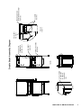
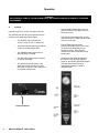
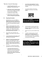
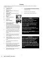
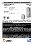
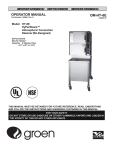
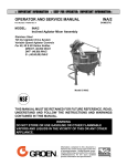
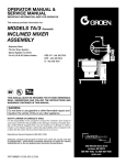
OPERATOR MANUAL
IMPORTANT INFORMATION, KEEP FOR OPERATOR
This manual provides information for:
MODELS VRC-3E
& VRC-6E Domestic
VORTEX® ATMOSPHERIC
CONNECTIONLESS
STEAMER
· Self Contained
· Electric Heated
· Capacity: VRC-3E=3 Steamer Pans Per Cavity
VRC-6E=6 Steamer Pans Per Cavity
THIS MANUAL MUST BE RETAINED FOR FUTURE REFERENCE.
READ, UNDERSTAND AND FOLLOW THE INSTRUCTIONS AND
WARNINGS CONTAINED IN THIS MANUAL.
FOR YOUR SAFETY
Do not store or use gasoline or other flammable vapors
and liquids in the vicinity of this or any other appliance.
NOTIFY CARRIER OF DAMAGE AT ONCE
It is the responsibility of the consignee to inspect the container upon receipt of
same and to determine the possibility of any damage, including concealed damage. Unified Brands suggests that if you are suspicious of damage to make a
notation on the delivery receipt. It will be the responsibility of the consignee to file
a claim with the carrier. We recommend that you do so at once.
Manufacture Service/Questions 888-994-7636.
Information contained in this document is known to be current and accurate at the time
of printing/creation. Unified Brands recommends referencing our product line websites,
unifiedbrands.net, for the most updated product information and specifications.
PART NUMBER 148673, REV. D (7/06)
1055 Mendell Davis Drive
Jackson, MS 39272
888-994-7636, fax 888-864-7636
groen.com
OM-VRC-3E/VRC-6E
IMPORTANT - READ FIRST - IMPORTANT
WARNING:
WHEN YOU OPEN THE DOOR, STAY AWAY FROM STEAM COMING OUT OF THE UNIT.
STEAM CAN CAUSE BURNS.
WARNING:
BEFORE CLEANING THE OUTSIDE OF THE STEAMER, DISCONNECT THE ELECTRIC
POWER SUPPLY. KEEP WATER AND CLEANING SOLUTIONS OUT OF CONTROLS AND
ELECTRICAL COMPONENTS. NEVER HOSE OR STEAM CLEAN ANY PART OF THE UNIT.
WARNING:
ALLOW COOKING CHAMBER TO COOL BEFORE CLEANING.
WARNING:
DO NOT MOVE THE UNIT WITH WATER IN THE CAVITY OR DRAIN PAN.
WARNING:
ALLOW WATER IN DRAIN PAN TO COOL BEFORE EMPTYING.
WARNING:
DO NOT PUT HANDS OR TOOLS INTO THE COOKING CHAMBER UNTIL THE FAN HAS
STOPPED TURNING.
WARNING:
DO NOT OPERATE THE UNIT UNLESS THE REMOVABLE RIGHT SIDE PANEL HAS BEEN
RETURNED TO ITS PROPER LOCATION.
WARNING:
USE OF ANY REPLACEMENT PARTS OTHER THAN THOSE SUPPLIED BY GROEN OR THEIR
AUTHORIZED DISTRIBUTOR VOIDS ALL WARRANTIES AND CAN RESULT IN BODILY
INJURY TO THE OPERATOR AND DAMAGE THE EQUIPMENT. SERVICE BY OTHER THAN
FACTORY-AUTHORIZED PERSONNEL WILL VOID ALL WARRANTIES.
WARNING:
HIGH VOLTAGE EXISTS INSIDE CONTROL COMPARTMENTS. DISCONNECT FROM BRANCH
CIRCUIT BEFORE SERVICING. FAILURE TO DO SO CAN RESULT IN SERIOUS INJURY OR
DEATH.
WARNING:
DO NOT USE CHEMICALS OTHER THAN MILD DETERGENTS TO CLEAN THE COOKING
WARNING:
CAREFULLY READ THE OPERATION INSTRUCTION LABEL BEFORE OPERATION OF THE
UNIT.
WARNING:
DO NOT USE REVERSE OSMOSIS (RO) OR DISTILLED WATER IN THE STEAMER.
CAUTION:
SHIPPING STRAPS ARE UNDER TENSION AND CAN SNAP BACK WHEN CUT.
CAUTION:
DO NOT INSTALL UNITS WITHIN 2 INCHES OF A HEAT SOURCE SUCH AS A BRAISING PAN,
DEEP FRYER, CHAR BROILER OR KETTLE.
NOTICE:
DO NOT USE ANY DE-GREASER THAT CONTAINS POTASSIUM HYDROXIDE OR SODIUM
HYDROXIDE OR THAT IS ALKALINE.
CHAMBER.
OM-VRC-3E/VRC-6E 148673 REV. D
OM-VRC-3E/VRC-6E
OM-VRC-3E/VRC-6E
Table of Contents
OPERATOR WARNINGS . . . . . . . . . . . . . . . . . . . . . . . . . . . . . . . . . . . . . . . . . . . . . . . . . . . . . . . . . . . . . . . . . . . . 2
REFERENCES . . . . . . . . . . . . . . . . . . . . . . . . . . . . . . . . . . . . . . . . . . . . . . . . . . . . . . . . . . . . . . . . . . . . . . . . . . . . . 3
EQUIPMENT DESCRIPTION . . . . . . . . . . . . . . . . . . . . . . . . . . . . . . . . . . . . . . . . . . . . . . . . . . . . . . . . . . . . . . . . . 4
INSPECTION AND UNPACKING . . . . . . . . . . . . . . . . . . . . . . . . . . . . . . . . . . . . . . . . . . . . . . . . . . . . . . . . . . . . . . 4
INSTALLATION AND START-UP . . . . . . . . . . . . . . . . . . . . . . . . . . . . . . . . . . . . . . . . . . . . . . . . . . . . . . . . . . . . 5-6
OPERATION . . . . . . . . . . . . . . . . . . . . . . . . . . . . . . . . . . . . . . . . . . . . . . . . . . . . . . . . . . . . . . . . . . . . . . . . . . . . 8-9
CLEANING . . . . . . . . . . . . . . . . . . . . . . . . . . . . . . . . . . . . . . . . . . . . . . . . . . . . . . . . . . . . . . . . . . . . . . . . . . . . . . . 10
MAINTENANCE . . . . . . . . . . . . . . . . . . . . . . . . . . . . . . . . . . . . . . . . . . . . . . . . . . . . . . . . . . . . . . . . . . . . . . . . . . . 11
TROUBLESHOOTING . . . . . . . . . . . . . . . . . . . . . . . . . . . . . . . . . . . . . . . . . . . . . . . . . . . . . . . . . . . . . . . . . . . . . . 11
WATER FILL DRAIN KIT INSTALLATION INSTRUCTIONS . . . . . . . . . . . . . . . . . . . . . . . . . . . . . . . . . . . . . . . . 12
WATER FILL DRAIN KIT DIAGRAM . . . . . . . . . . . . . . . . . . . . . . . . . . . . . . . . . . . . . . . . . . . . . . . . . . . . . . . . . . 13
RACKS, PAN INSTALLATION INSTRUCTIONS . . . . . . . . . . . . . . . . . . . . . . . . . . . . . . . . . . . . . . . . . . . . . . . . . 14
SERVICE LOG . . . . . . . . . . . . . . . . . . . . . . . . . . . . . . . . . . . . . . . . . . . . . . . . . . . . . . . . . . . . . . . . . . . . . . . . . . . . 15
WARRANTY PROTECTION
. . . . . . . . . . . . . . . . . . . . . . . . . . . . . . . . . . . . . . . . . . . . . . . . . . . . . . . . . . . . . . . . 16-17
References
UNDERWRITERS LABORATORIES, INC.
333 Pfingsten Road
Northbrook, Illinois 60062
NATIONAL FIRE PROTECTION ASSOCIATION
60 Batterymarch Park
Quincy, Massachusetts 02269
NFPA/70
Website Address: www.groen.com
The National Electrical Code
NATIONAL SANITATION FOUNDATION
3475 Plymouth Road
Ann Arbor, Michigan 48106
148673 REV. D OM-VRC-3E/VRC-6E OM-VRC-3E/VRC-6E
3
OM-VRC-3E/VRC-6E
Equipment Description
Your Groen VRC-3E or VRC-6E Vortex
Connectionless Steamer is designed to give years
of service. It has a stainless steel cavity (cooking
chamber) which is served by an inside water
reservoir which is electrically heated. A powerful
blower circulates the steam in the cavity to increase
heating efficiency.
The cavity holds up to three (VRC-3E) or six (VRC6E) steam table pans (12" x 20" x 2½" deep). An 18
gauge stainless steel case encloses the cavity and
the control compartment that houses electrical
components. Door hinges are reversible (the door
may be set to open from the left or right). Operating
Controls are on the front panel.
The VRC-3E holds three standard 12"x 20"x 2-1/2"
or two 12"x20"x4" steamer pans.
VRC-3E and VRC-6E steamers are equipped with
fully electronic controls. These units are readily
identified by their unique control panels. The On-Off
switch is operated by touch pad controls.
From the rear of the VRC-3E and VRC-6E units are
distinguished by the addition of a fuse box, which lets
operators change fuses without removing panels.
WARNING
DISCONNECT ELECTRICAL POWER BEFORE
CHANGING FUSES. FAILURE TO DO SO WILL
CAUSE ELECTRICAL SHOCK OR DEATH.
The VRC-6E holds up to six standard
12"x20"x2-1/2" or four 12"x20x4" steamer pans.
Inspection and Unpacking
The Steamer will be delivered completely assembled
in a heavy shipping carton strapped to a skid. On
receipt, inspect carton carefully for exterior damage.
If damage is evident, notify the local carrier
immediately and file a damage claim. Groen
assumes no liability for damage incurred in transit.
Reconfirm that the voltage at the location is
compatible with the steamer you received.
CAUTION
SHIPPING STRAPS ARE UNDER TENSION AND
CAN SNAP BACK WHEN CUT.
Carefully cut the straps and detach the sides of the
carton from the skid. Pull the carton up off the unit.
Be careful to avoid personal injury or equipment
damage from staples which might be left in the carton
walls.
OM-VRC-3E/VRC-6E 148673 REV. D
OM-VRC-3E/VRC-6E
CAUTION
THE VRC-3E WEIGHS 150 POUNDS (68 KG).
THE VRC-6E WEIGHS 170 POUNDS (77 KG).
YOU SHOULD GET HELP AS NEEDED TO LIFT
THIS WEIGHT SAFELY.
Write down the model number, serial number and
installation date. Keep this information for reference.
Space for these entries is provided at the top of the
Service Log in the back of this manual.
When starting installation, check packing materials
to make sure loose parts such as the drain pan drip
tray are not discarded with this material.
OM-VRC-3E/VRC-6E
Installation and Start-Up
CAUTION
DO NOT INSTALL THE UNIT WITHIN 2 INCHES OF A HEAT SOURCE (SUCH AS A BRAISING PAN, DEEP FAT
FRYER, CHARBROILER OR KETTLE).
Electrical Supply Connection - Observe all local, national, or other applicable codes.
Branch Circuit Protection
Three phase models of the Vortex™ Connectionless
Steamer are supplied with a cord set ready to be
connected to a power supply. See the chart below
for the correct matching receptacle (not supplied with
the unit).
Each Steamer, including individual units of stacked
models, should have its own branch circuit protection
and ground wire. Current and power demands for
each unit are as shown below.
Single phase models are designed to be directly
connected (hard wired) to the electrical supply and
allow sufficient loop in the flexible conduit to facilitate
inspection, servicing, and cleaning.
ELECTRICAL SUPPLY CONNECTIONS
FIELD WIRING TABLE - USE COPPER WIRE ONLY - INSULATION RATING (90ºC)
KW
RATED CURRENT DEMAND
VOLTAGE
(60 Hz Only)
VRC-3E
VRC-6E
VRC-3E
VRC-6E
208 3 PHASE
9KW
10KW
25 Amps
28 Amps
240 3 PHASE
9KW
10KW
22 Amps
25 Amps
480 3 PHASE
9KW
10KW
11 Amps
13 Amps
PLUG AND RECEPTACLE CHART
VOLTS
PHASE
PLUG
RECEPTACLE
9KW
10KW
9KW
10KW
208
3
15-30P
15-50P
15-30R
15-50R
240
3
15-30P
15-50P
15-30R
15-50R
480
3
L16-20P
L16-20P
L16-20R
L16-20R
208
1
----
----
----
----
240
1
----
----
----
----
WARNING
GROUNDING INSTRUCTIONS: THIS APPLIANCE MUST BE CONNECTED TO A GROUNDED
METALLIC, PERMANENT WIRING SYSTEM, OR AN EQUIPMENT GROUNDING
CONDUCTOR MUST BE RUN WITH THE CIRCUIT CONDUCTORS AND CONNECTED TO
THE EQUIPMENT GROUNDING TERMINAL ON THE STATION.
148673 REV. D OM-VRC-3E/VRC-6E OM-VRC-3E/VRC-6E
5
OM-VRC-3E/VRC-6E
Water Connection(s)
No water connection is needed. The water will be
poured directly into the water cavity reservoir. Avoid
the use of any chemically treated water specifically
filtered water.
WARNING
DO NOT USE REVERSE OSMOSIS (RO) OR
DISTILLED WATER IN THE STEAMER.
Drain Connection
The Vortex™ Connectionless Steamer should be
manually drained to the bottom containment pan
supplied by the factory. If the unit is connected to a
drain, do not connect more than two units to one
drain line or pressure from one unit will effect the
second unit.
Stacking Units Instructions
Remove drain containment pan from the bottom of
unit(s). Unscrew to remove adjustable legs from
base of Vortex unit(s). Unfasten nuts and bolts on
stand platform(s). Place Vortex unit(s) on stand
platform. Align the (4) leg holes with the holes in the
platform. Secure Vortex unit(s) to stand platform(s)
using bolts and washers provided in step 2 as shown
in detail “A” of figure 1 on page 7.
For double stack units only:
By loosening the left screw and removing the right
screw provided, mount steam exhaust bracket
assembly to the back panel of the top Vortex unit as
shown in detail “B” of Figure 1 on page 7. Attach the
steam exhaust hose from the bottom Vortex unit?s
steam outlet tube to the top Vortex unit?s steam
exhaust bracket assembly using hose clamps
provided as shown in figure 2 on page 7. (Note:
Steam exhaust hose may need to be cut to fit.)
Steam Vent Assembly Instructions
Remove steam diverter assembly from
literature bag which can be found inside of unit.
Slide loose end as shown over unit steam outlet,
tighten worm gear clamp with flat head screw driver.
Be sure steam outlet is pointing in the upward
position. (Shown below)
UNIT STEAM OUTLET
TO DIVERT STEAM OUTLET
ATTACH THIS STEAM DIVERTER ASSEMBLY
TO THE UNIT EXHAUST TUBE .
FUSE BOX
ACCESS HOLE TO
CAVITY TEMPERATURE
PROBE
DRAIN VALVE
POWER CORD
CONTAINMENT PAN
6
OM-VRC-3E/VRC-6E 148673
REV. D
OM-VRC-3E/VRC-6E
DETAIL A
SCALE 1 : 2
3/8-16 CAP SCREW
TO SECURE UNIT
TO STAND. P/N:
005449 TYP. (8)
PLCS.
FIGURE 1
FIGURE 2
B
A
7
DOUBLE STACK STAND
P/N: 142363
HOSE CLAMPS
P/N: 073259
DOUBLE STACK
STEAM EXHAUST
HOSE P/N: 141505
Double Stack Assembly Diagram
HOSE CLAMPS
P/N: 073259
DETAIL B
SCALE 1 : 1
10-32 SCREW
P/N: 004173
DOUBLE STACK STEAM
EXHAUST BRACKET ASSEMBLY
P/N: 143243
OM-VRC-3E/VRC-6E
148673 REV. D OM-VRC-3E/VRC-6E OM-VRC-3E/VRC-6E
7
OM-VRC-3E/VRC-6E
Operation
WARNING
ANY POTENTIAL USER OF THE EQUIPMENT MUST BE TRAINED IN SAFE AND CORRECT OPERATING
PROCEDURES.
A.
Controls
!
Operator controls are on the front right of the unit.
The VRC-3E and VRC-6E control panels have the
following touch pads and indicator lights:
!
The ON/OFF touch pad gets the
Vortex™ ready for use, or shuts it off.
!
The HOLD indicator light shows that the
cavity is at holding temperature.
!
The TIMING indicator light stays on
when the timer is running.
!
The ADD H20 indicator light is lit when
it’s time to add water.
!
The open and closed position of the
drain valve allows the unit to be filled
with water or drained. This is also used
to manually reset the unit.
The unit will automatically shut off, and
cannot be turned on again until the water
reservoir cools down.
Open/Close Handle
8
8
OM-VRC-3E/VRC-6E 148673 REV. D
OM-VRC-3E/VRC-6E
The HI TEMP indicator light comes on
when the bottom of the water reservoir
becomes too hot.
!
The HI TEMP light will remain
illuminated until the controls are turned
on and the unit temperature is low
enough to restart. Then reset the
manual reset latch as indicated on the
bottom label.
!
When power has been interrupted to
the Vortex or the HI TEMP light has
come on, the RESET light will illuminate.
The drain handle will need to be
momentarily opened or closed to
extinguish light.
OM-VRC-3E/VRC-6E
The timer is used in three ways:
B.
1
In the HOLD position the steam
generator stays at a low boil or “holding”
temperature. Factory set at 180°F.
2
When a cook time is set, the timing light
will illuminate. The unit steams until the
timer runs down to DONE. At that time
steaming stops, the DONE light
illuminates and a beeper sounds.
3
When the timer is turned to the ON
position, the unit steams continuously.
The green ON light will stay illuminated.
!
!
Operating Procedure
With the cooking chamber water reservoir
“empty” press the ON/OFF touch pad. The
ADD H2O light will illuminate when the door
is opened.. Pour water into the reservoir
through the door. When the water level
comes up to the hi probe the reservoir is full
and 3 beeps will sound. Close door.
2.
Set the timer knob to the HOLD or ON
position. The unit will be ready in about 20
minutes.
3.
Load food into pans in uniform layers. Pans
should be filled to about the same levels,
and should not be mounded.
4.
Open the door and slide the pans onto the
supports. If you will only be steaming one
pan, put it in the middle position. Some
foods will cause foam. When cooking foods
that foam, such as shrimp, put an empty
solid 2 ½ “ deep pan in the bottom slot of the
pan racks.
5.
If you want to maintain food at holding
temperature turn the timer to the “HOLD”
position.
WARNING
WHEN YOU OPEN THE DOOR, STAY AWAY
FROM THE STEAM COMING OUT OF THE UNIT.
THE STEAM CAN CAUSE BURNS.
NOTE: When the unit is first installed, or
anytime incoming power is interrupted, the
RESET light will illuminate. Momentarily turn
the drain handle to open then back to close
to reset the unit and extinguish the RESET
light.
1.
If you want to steam continuously, turn the
timer to the manual ON position. The green
ON light will illuminate. The unit will continue
steaming.
6.
To remove pans from cavity, open the door.
Remove the pans from the steamer, using
hot pads or oven mitts to protect your hands
from the hot pans.
7.
To shut off the unit, press the ON/OFF touch
pad.
8.
To drain the remaining water in the water
reservoir, move the drain handle to the
OPEN position. The drain pan will not hold
all of the water in the reservoir. Allow water
to cool before draining. Pull drain pan slowly
from the unit to avoid sloshing.
WARNING
DO NOT EMPTY UNTIL WATER IS COOL.
EMPTY DRAIN PAN. PAN WILL NOT HOLD ALL
WATER FROM THE RESERVOIR. DO NOT
OVER FILL DRAIN PAN.
Close the door. With the HOLD indicator
illuminated, take one of the following steps:
!
If you want to steam the food for a
certain length of time, set the timer for
that period. The timer will automatically
run the steamer for the set time and
then turn it off. A beeper will sound.
Steam production stops. The red DONE
light will illuminate.
9
148673 REV. D OM-VRC-3E/VRC-6E OM-VRC-3E/VRC-6E
OM-VRC-3E/VRC-6E
Cleaning
To keep your VRC-3E or VRC-6E Connectionless Steamer in proper working condition, use the following
procedure to clean the unit.
10
A.
Suggested Tools
1.
2.
3.
4.
5.
6.
7.
8.
9.
Mild detergent
Stainless steel exterior cleaner such as
Zepper®
Cloth or sponge
Plastic wool or a brush with soft bristles
Spray bottle
Measuring cup
Nylon pad
Towels
Plastic disposable gloves
B.
Procedure
1.
Exterior Cleaning
a.
Prepare a warm solution of
the mild detergent as
instructed by the supplier.
Wet a cloth with this solution and wring it
out. Use the moist cloth to clean the outside
of the unit. Do not allow freely running liquid
to touch the controls, the control panel, any
electrical part, or on the side or rear panels.
b.
To remove material which may be stuck to
the unit, use plastic wool, a fiber brush, or a
plastic or rubber scraper with a detergent
solution.
c.
Stainless steel surfaces may be polished
with a recognized stainless steel cleaner
such as Zepper®.
2.
Interior Cleaning - Clean the unit daily or as
residue builds upon the bottom of the oven
cavity.
a.
Press ON/OFF to turn the steamer off.
Open the door..
b.
Drain the water from the unit into the drain
pan and allow the unit to cool before
cleaning. (Note: If the cavity is full of water,
the drain pan will not hold the entire amount
and must be emptied more than once.)
c.
After the unit has cooled, remove pan and
pan racks from the cavity.
OM-VRC-3E/VRC-6E
OM-VRC-3E/VRC-6E 148673 REV. D
d.
Use a mild detergent to wipe down the steamer
cavity, the probes on the inside back panel wall
and the pan racks.
e.
Rinse the unit to remove detergent.
f.
Attach pan racks. Unit is ready for use.
WARNING
KEEP WATER AND CLEANING SOLUTIONS OUT
OF CONTROLS AND ELECTRICAL
COMPONENTS. NEVER HOSE OR STEAM
CLEAN ANY PART OF THE UNIT.
EVEN WHEN THE UNIT HAS BEEN SHUT OFF,
DON’T PUT HANDS OR TOOLS INTO THE
COOKING CHAMBER UNTIL THE FAN HAS
STOPPED TURNING.
DON’T OPERATE THE UNIT UNLESS THE
REMOVABLE PARTITION HAS BEEN PUT BACK
IN ITS PROPER LOCATION.
DO NOT USE ANY ACIDIC CLEANSER,
DELIMER/DESCALER OR CHEMICAL PRODUCTS
TO CLEAN THE UNIT.
IMPORTANT
DO NOT USE ANY METAL MATERIAL (SUCH AS
METAL SPONGES) OR METAL IMPLEMENTS
(SUCH AS A SPOON, SCRAPER OR WIRE
BRUSH) THAT MIGHT SCRATCH ANY
STAINLESS STEEL SURFACE. SCRATCHES
MAKE THE SURFACE HARD TO CLEAN AND
PROVIDE PLACES FOR BACTERIA TO GROW.
DO NOT USE STEEL WOOL, WHICH MAY LEAVE
PARTICLES IMBEDDED IN THE SURFACE WHICH
COULD EVENTUALLY CAUSE CORROSION AND
PITTING.
10
OM-VRC-3E/VRC-6E
Maintenance
The VRC-3E and VRC-6E Steamers are designed
for minimum maintenance, and no user adjustments
should be necessary. Certain parts may need
replacement after prolonged use. If there is a need
for service, only authorized Groen representatives
should perform the work.
3. Adjust the door latch pin to allow for changes
that might occur as the gasket ages.
a. Loosen the lock nut at the base of the latch
pin, then turn the latch pin ¼ turn clockwise,
and tighten the lock nut.
If steam or condensate is seen leaking from around
the door, take the following steps:
b. After adjustment, run the unit to test for
further steam leakage.
1. Check the door gasket. Replace it if it is cracked
or split.
c.
2. Inspect the cooking chamber exhaust to be sure
it is not blocked.
d. Continue adjusting the pin clockwise until the
door fits tightly enough to prevent leakage.
If there is still leakage, repeat the
adjustment.
Troubleshooting
This Groen Steamer is designed to operate smoothly and efficiently if properly maintained. However, the following
is a list of checks to make in the event of a problem. Wiring diagrams are furnished inside the service panel.
SYMPTOM
WHO
WHAT TO CHECK
1. No power
User
a. Check wall circuit breaker.
b. Disconnect power, then check fuses on back of steamer.
c. Call for service technician.
2. Reset light is on
User
a. Momentarily turn the drain valve to open then back to
closed to reset.
b. Call for service technician.
3. Any unusual operation
User
a. Press ON/OFF pad to turn steamer off. Press again to turn
steamer on.
b. Call for service technician.
4. No steam
User
a. Check and add water as required. (For auto fill units turn
unit off and on)
b. Ensure door is closed.
c. Call for service technician.
5. Door pops open
User
a. Ensure drain and vent are not plugged. No more than two
units should be attached to a single drain line.
b. Check door pin adjustment per above.
c. Call for service technician.
6. HI TEMP Light is ON
User
a. Wait 30 minutes for the unit to cool down, RESET light
should come on when unit has cooled. Turn unit on.
Momentarily turn drain valve to reset safety circuit.
b. Call for Service Technician.
7. Dial gage will not read
212
User
a. This may be normal, altitude and water purity may affect
temperature reading on the gage.
11
148673 REV. D OM-VRC-3E/VRC-6E 11
OM-VRC-3E/VRC-6E
11
OM-VRC-3E/VRC-6E
WATER DRAIN KIT
INSTALLATION INSTRUCTIONS
1-Remove all parts from shipping cartons.
WARNING: DISCONNECT POWER BEFORE
INSTALLING
2-Check-identify all parts as follow.
2.1- Water Drain Parts
- 142549 ELBOW 3/4” HOSE BARB 90 DEG. .............................1
- 142550 TEE 3/4” HOSE BARB .................................................1
- 143246 DRAIN ASSEMBLY, AUTODRAIN...............................1
- 143250 HOSE LONG 3/4” ID X 10ft .........................................1
- 143254 HOSE 3/8" ID X 30" LONG ..........................................1
3- Water drain installation steps.
3.1 The condensate drain line needs to be disconnected
before the left side cabinet panel can be replaced.
3.1.a From the bottom of the unit just right of the drain valve
unscrew the condensate drip bracket.
3.1.b From the inside, loosen the tension clamps and
remove the bracket from the hose and the hose from the
condensate line.
3.1.c Slide the tension clamps off of the hose and use them
on next step.
3.1.d Install one end of the supplied hose 3/8" inside
diameter x 30" long on the condensate line where the
condensate trap to drain hose were installed before, pull the
other end of the hose through the hole where the bracket
was mounted. Reinstall the inside tension clamp.
3.2 Guide the hose loose end thru the uncovered hole to the
outside bottom of the unit as drawing shows.
3.3 Thread the hose drain assembly onto the unit drain
valve, see drawing.
3.4 Connect the 3/8" diameter x 30" long hose loose end to
the plastic barb fitting on the drain assembly and reuse the
other tension hose clamps.
3.4.a If you are installing a kit on a 3 pan model cut this
3/8" x 30" long hose to fit..
3.5 A 10ft piece of hose is supplied with this kit, it can be cut
to length and used with the elbow to help route the hose to
the proper drain location
3.6 For single units cut the long hose to length as needed to
route it to facility drain. Note hose end must have at least a
2" gap from the floor drain, do not use traps.
3.7 For double stack units, a 6.5" long piece of hose can be
cut to join the upper and lower cavities by using the supplied
tee on the bottom unit, the supplied elbow on the top unit
and a piece to connect the two cavities as shown. Permit a
2" air gap from the floor drain. Do not use traps.
12
12
OM-VRC-3E/VRC-6E 148673 REV. D
OM-VRC-3E/VRC-6E
4- Test to ensure the final assembly of the drain
line allows the water to flow freely.
Loops or kinks in the hose will cause back pressure which
may cause the door to pop open during draining.
16
14
DETAIL C
SCALE 1 : 2
5
1
16
16
ATTACH HOSE 143254 (3/8" DIAMETER X 30"LONG)
TO THIS PORT USING THE TENSION CLAMP.
C
CUT TO
LENGTH
TO FACILITY
DRAIN
6
3
16
CUT TO
LENGTH
6
1
DESCRIPTION
HOSE 3/8" ID X 30" LONG
HOSE CLAMP
HOSE, LONG 3/4" ID X 10 ft.
DRAIN ASSEMBLY, AUTODRAIN KIT
BACK PANEL. REFERENCE ONLY.
TEE, 3/4" HOSE BARB
CHAMBER ASSEMBLY. REFERENCE ONLY
ELBOW 3/4" HOSE BARB
2 " GAP MINIMUM
ATTACH THIS END
OF THE HOSE
143254 TO THE
UNIT INSIDE
CONDENSATE
TRAP USING THE
TENSION CLAMP.
ITEM NO. PART NO.
16
143254
14
127523
6
143250
5
143246
4
140789
3
142550
2
141067
1
142549
Water Drain Kit Diagram
OM-VRC-3E/VRC-6E
148673 REV. D OM-VRC-3E/VRC-6E 13
OM-VRC-3E/VRC-6E
13
OM-VRC-3E/VRC-6E
PAN RACKS FOR SINGLE STANDS ONLY
INSTALLATION INSTRUCTIONS
HOLES TO BE ALIGNED
WITH THREADED HOLES
ON THE BOTTOM OF STEAMER
STAND, BULLET FEET OR CASTERS
HOLES TO BE ALIGNED
WITH THREADED HOLES
ON THE BOTTOM OF STEAMER
3
3
2
5
1
STAND CROSS MEMBER HOLE
FOR RACK BOTTOM WIRE.
TOP WIRE
4
BRACKET HOLE FOR
RACK TOP WIRE
BOTTOM WIRE
TOP WIRE
BOTTOM WIRE
ASSEMBLY INSTRUCTIONS:
1. Unpack racks kit.
2. Identify parts.
3. Unscrew and remove screws #1 and washers #2 from the bottom of your steamer. Do not move the steamer.
This will allow the bottom threaded holes to stay aligned with the holes on the stand.
4. Secure brackets #3 using screws #1 and washers #2 thru the holes on the stands and into the threaded holes
on the bottom of your steamer.
5. To place racks on stand, align wires from top of the rack with the corresponding holes in bracket #3. Push the
rack all the way up into the bracket. Align bottom of the rack wires with the holes in the stand leg and allow
rack to fall in position.
14
14
OM-VRC-3E/VRC-6E 148673 REV. D
OM-VRC-3E/VRC-6E
OM-VRC-3E/VRC-6E
Service Log
Model No.
Purchased From
Serial No.
Location
Date Purchased
Date Installed
Purchase Order No.
For Service Call
Date
Maintenance Performed
Performed by
148673 REV. D OM-VRC-3E/VRC-6E 15
OM-VRC-3E/VRC-6E
15
OM-VRC-3E/VRC-6E
GROEN®LIMITED WARRANTY TO COMMERCIAL PURCHASE*
(U.S. & Canadian Sales Only)
Groen warrants to original commercial purchaser/users that foodservice equipment manufactured by GroenÆ (ìGroenÆ Equipmentî) other than
CapKoldÆ foodservice equipment, shall be free from defects in material and workmanship for twelve (12) months from the date of installation or
fifteen (15) months from date of shipment from GroenÆ,whichever date first occurs (the ìWarranty Periodî), in accordance with the following terms
and conditions:
I.
This warranty is limited to replacement parts and related labor for GroenÆ Equipment located at its original place of installation in the United
States and Canada.
II.
Damage to GroenÆ Equipment that occurs during shipment must be reported to the carrier, and is not covered under this warranty. The
reporting of any damage during shipment is the sole responsibility of the commercial purchaser/user of such GroenÆ Equipment.
III.
For GroenÆ Convection ComboTM Steamer-Ovens, HyPerSteamTM Convection Steamers and HyPlusTM Pressureless Steamers, GroenÆ
further warrants to the original commercial purchaser/users of such GroenÆ Equipment that the atmospheric steam generators or boilers contained
in such GroenÆ Equipment shall be free from defects in material and workmanship for twenty-four (24) months from the date of installation or
twenty-seven (27) months from date of shipment from GroenÆ,whichever date first occurs, provided that: (a) the original purchaser/user shall
have also purchased and installed a GroenÆ PureSteem Water Treatment SystemTM for use in connection with such GroenÆ Convection
ComboTM Steamer-Oven, HyPerSteamTM Convection Steamer or HyPlusTM Pressureless Steamer on or before the date such GroenÆ
Equipment was installed, (b) the original purchaser/user has continuously used such Water Treatment System in connection with such GroenÆ
Equipment from the date of installation, and ©) the commercial purchaser/user shall have maintained such Water Treatment System in accordance
with the maintenance and filter cartridge replacement recommendations of GroenÆ, and otherwise maintained such Oven or Steamer in
accordance with all other operational and maintenance recommendations of GroenÆ.
IV.
GroenÆ further warrants to the original commercial purchaser/users of GroenÆConvection ComboTM Steamer-Ovens that the electronic
relay and control board contained in such GroenÆ Convection ComboTM Steamer-Oven shall be free from defects in material and work manship
for twenty-four (24) months from the date of installation or twenty-seven (27) months from date of shipment from GroenÆ, whichever date first
occurs.
V.
During the Warranty Period, GroenÆ,directly or through its authorized service representative, will either repair or replace, at Groenís sole
election, any GroenÆEquipment determined by GroenÆto have a defect in material or workmanship. As to any such warranty service during the
Warranty Period, GroenÆ will be responsible for related reasonable labor and portal to portal transportation expenses (time &
mileage) incurred within the United States and Canada.
VI.
This warranty does not cover boiler maintenance, calibration, periodic adjustments as specified in operating instructions or manuals,
consumable parts (such as scraper blades, gaskets, packing, etc.), and labor costs incurred for removal of adjacent equipment or objects to gain
access to GroenÆ Equipment. This warranty does not cover defects caused by improper installation, abuse, careless operation, or improper
maintenance of GroenÆ Equipment. This warranty does not cover damage to GroenÆEquipment caused by poor water quality or improper boiler
maintenance.
VII.
THIS WARRANTY IS EXCLUSIVE AND IS IN LIEU OF ALL OTHER WARRANTIES, EXPRESSED OR IMPLIED, INCLUDING ANY
IMPLIED WARRANTY OF MERCHANTABILITY OR FITNESS FOR A PARTICULAR PURPOSE, EACH OF WHICH IS HEREBY EXPRESSLY
DISCLAIMED. THE REMEDIES DESCRIBED ABOVE ARE EXCLUSIVE AND IN NO EVENT SHALL GROENÆ BE LIABLE FOR SPECIAL,
CONSEQUENTIAL, OR INCIDENTAL DAMAGES FOR THE BREACH OR DELAY IN PERFORMANCE OF THIS WARRANTY.
VIII.
GroenÆ Equipment is for commercial use only. If sold as a component of another (O.E.M.) manufacturerís equipment, or if used as a
consumer product, such Equipment is sold AS IS and without any warranty.
*Covers all GroenÆ Equipment (other than CapKoldÆ foodservice equipment) ordered after September 11, 2001.
16
OM-VRC-3E/VRC-6E
OM-VRC-3E/VRC-6E 148673 REV. D
OM-VRC-3E/VRC-6E
GROENÆLIMITED EXTENDED WARRANTY COVERAGE*
(U.S. & Canadian Sales Only)
Limited Extended Warranty Coverage is available on all standard GroenÆ Equipment (other than CapKoldÆ foodservice equipment)
covered by the above GroenÆ Limited Warranty. Commercial purchasers/users of GroenÆ Equipment may elect to extend the standard limited
warranty to cover parts, labor and portal to portal transportation costs (time and mileage) for an additional twelve (12) or twenty four (24) month
period, in addition to the time period of the standard limited warranty described above. Limited Extended Warranty Coverage is not available to
extend the supplemental limited warranty for: (a) atmospheric steam generators or boilers contained in GroenÆ Convection ComboTM SteamerOvens, HyPerSteamTM Convection Steamers and HyPlusTM Pressureless Steamers, or (b) electronic relay and control boards contained in
GroenÆ Convection ComboTM Steamer-Ovens.
Cost of Extended Coverage
Five percent (5.0%) of the LIST PRICE of the GroenÆ Equipment to be covered by the Limited Extended Warranty for each additional
twelve (12) months of limited extended warranty coverage. The five percent (5.0%) of the LIST PRICE charge will be the net invoice amount for
each year of Limited Extended Warranty Coverage purchased.
Conditions of Coverage
(1)
Limited Extended Warranty Coverage must be purchased at the time the GroenÆ Equipment to be covered is purchased.
(2)
All conditions and limitations on the Standard Limited Warranty Coverage apply to the Limited Extended Warranty Coverage. See above
for details of conditions and limitations on the Standard Warranty Coverage.
*Covers all GroenÆ Equipment (other than CapKoldÆ foodservice equipment) ordered after September 11, 2001.
148673 REV. D OM-VRC-3E/VRC-6E 17
OM-VRC-3E/VRC-6E
17
NOTES
18
OM-VRC-3E/VRC-6E
OM-VRC-3E/VRC-6E 148673 REV. D
NOTES
148673 REV. D OM-VRC-3E/VRC-6E 19
OM-VRC-3E/VRC-6E
19
1055 Mendell Davis Drive • Jackson MS 39272
888-994-7636 • 601-372-3903 • Fax 888-864-7636
groen.com
PART NUMBER 148673, REV. D (7/06)