1
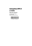
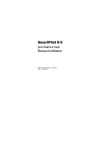
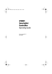
SmartPilot X-5R
Drive Operating
Guide
Document reference: 81329-1
Date: December 2010
Autohelm, hsb2, RayTech Navigator, Sail Pilot, SeaTalk, SeaTalkNG, SeaTalkHS and Sportpilot are registered trademarks of Raymarine
UK Limited. RayTalk, Seahawk, Smartpilot, Pathfinder and Raymarine are registered trademarks of Raymarine Holdings Limited.
FLIR is a registered trademark of FLIR Systems, Inc. and/or its subsidiaries.
All other trademarks, trade names, or company names referenced herein are used for identification only and are the property of their
respective owners.
This product is protected by patents, design patents, patents pending, or design patents pending.
Copyright ©2010 Raymarine UK Ltd. All rights reserved.
i
Contents
Important Information ............................................................................................... iii
Safety notices ..........................................................................................................iii
EMC Conformance ..................................................................................................iii
Pressure washing ....................................................................................................iv
Product documents ..................................................................................................iv
Product disposal ......................................................................................................iv
Waste Electrical and Electronic (WEEE) Directive .....................................iv
Warranty ..................................................................................................................iv
Chapter 1:Basic Operation ...................................................................................... 1
1.1 Introduction .................................................................................................... 1
Extended systems .......................................................................................... 1
1.2 Using the control unit ..................................................................................... 2
Switching on and off........................................................................................ 2
Start-up mode ............................................................................................. 2
Keypad functions ............................................................................................ 2
Displayed information..................................................................................... 3
1.3 Using the SPX-5R Drive system to steer your boat ........................................ 4
Emergency release pin ................................................................................... 4
Replacing the pin after use ......................................................................... 4
Standby mode - steering by hand.................................................................... 4
Using the autopilot to steer to a heading ......................................................... 5
Changing course in Auto mode....................................................................... 5
AutoTurn ..................................................................................................... 6
Avoiding obstacles.......................................................................................... 6
Steering away ............................................................................................. 6
Selecting a change of course ..................................................................... 6
Off Course alarm ............................................................................................ 6
1.4 Adjusting pilot performance ........................................................................... 7
Response levels ............................................................................................. 7
Temporarily adjusting response.................................................................. 8
1.5 Display lighting & contrast .............................................................................. 8
Adjusting the display lighting........................................................................... 8
Contrast.......................................................................................................... 9
1.6 Data pages .................................................................................................... 9
Waypoint names........................................................................................... 10
1.7 Alarms ......................................................................................................... 10
Responding to alarms....................................................................................11
1.8 Response setup ........................................................................................... 12
Accessing response setup............................................................................ 13
Chapter 2:Using Track mode ................................................................................ 15
2.1 Overview ..................................................................................................... 15
Requirements for Track mode....................................................................... 15
Starting position and heading........................................................................ 15
2.2 Procedures .................................................................................................. 16
Entering track mode...................................................................................... 16
Leaving Track mode ..................................................................................... 16
Avoiding obstacles........................................................................................ 16
Track keeping & Cross Track Error ............................................................... 17
ii
SmartPilot X-5R Drive Operating Guide
Large cross track error.............................................................................. 18
Tidal stream compensation....................................................................... 18
Waypoint arrival ............................................................................................ 19
To steer to the next waypoint in the route................................................. 19
To skip a waypoint (SeaTalk chartplotters only) ....................................... 19
Waypoint arrival circle............................................................................... 20
Route completion.......................................................................................... 20
Chapter 3:Troubleshooting & Maintenance ..................................................... 21
3.1 Troubleshooting ........................................................................................... 21
SPX-5R Drive system alarm messages ........................................................ 22
3.2 Maintenance ................................................................................................ 23
Important ...................................................................................................... 23
Spare parts ................................................................................................... 23
EMC Servicing and maintenance.................................................................. 24
Suppression ferrites .................................................................................. 24
Pilot Controller .............................................................................................. 24
Drive ............................................................................................................. 24
Routine maintenance ................................................................................ 24
3.3 Customer support ........................................................................................ 26
Web support ............................................................................................. 26
Telephone and email support ................................................................... 26
Help us to help you ................................................................................... 26
Product details table ................................................................................. 27
Glossary ....................................................................................................................... 29
Index.............................................................................................................................. 31
iii
Important Information
Safety notices
WARNING: Navigation aid
Although we have designed this product to be accurate and
reliable, many factors can affect its performance. Therefore, it
should only be used as an aid to navigation and should never
replace common sense and navigational judgement. Always
maintain a permanent watch so you can respond to situations as
they develop.
CAUTION: Calibration
When supplied, this product is calibrated to default settings which
should provide initial stable performance for most boats. To ensure
optimum performance on your boat, the commissioning procedures
(in the SPX-5R Drive Installation & Setup Guide) must be completed
before this product is used.
Your Raymarine SPX-5R Drive system will add a new dimension to your boating
enjoyment. However, it is the skipper’s responsibility to ensure the safety of the boat
at all times by following these basic rules:
• Ensure that someone is present at the helm AT ALL TIMES, to take manual
control in an emergency.
• Make sure that all members of crew know how to disengage the autopilot.
• Regularly check for other boats and any obstacles to navigation – no matter how
clear the sea appears, a dangerous situation can develop rapidly.
• Maintain an accurate record of the boat’s position by using either a navigation aid
or visual bearings.
• Maintain a continuous plot of your boat’s position on a current chart. Ensure that
the locked autopilot heading will steer the boat clear of all obstacles. Make proper
allowance for tidal set – the autopilot cannot.
• Even when your autopilot is locked onto the desired track using a navigation aid,
always maintain a log and make regular positional plots. Navigation signals can
produce significant errors under some circumstances and the autopilot will not be
able to detect these errors.
EMC Conformance
All Raymarine equipment and accessories are designed to the best industry
standards for use in the recreational marine environment. Their design and
manufacture conforms to the appropriate Electromagnetic Compatibility (EMC)
standards, but correct installation is required to ensure that performance is not
compromised.
iv
SmartPilot X-5R Drive Operating Guide
Pressure washing
Subjecting any Raymarine product to high pressure washing may cause subsequent
water intrusion and failure of the product. Raymarine will not warranty product
subjected to high pressure washing.
Product documents
This document is part of a series of books associated with the SmartPilot X-5 series.
Documents can be downloaded from:
www.raymarine.com/handbooks.
Title
Part
number
SmartPilot X-5R Drive Installation and Setup Guide
87128
ST6002 SmartPilot Controller - Quick Reference Guide
86140
Fluxgate Compass Installation sheet
87011
To the best of our knowledge, the information in the product documents was correct
when they went to press. However, Raymarine cannot accept liability for any
inaccuracies or omissions in product documents.
In addition, our policy of continuous product improvement may change specifications
without notice. Therefore, Raymarine cannot accept liability for any differences
between the product and the accompanying documents.
Product disposal
Waste Electrical and Electronic (WEEE) Directive
The WEEE Directive requires the recycling of waste electrical and electronic
equipment.
Whilst the WEEE Directive does not apply to some of Raymarine's products, we
support its policy and ask you to be aware of how to dispose of this product.
The crossed out wheelie bin symbol, illustrated above, and found on our products
signifies that this product should not be disposed of in general waste or landfill.
Please contact your local dealer, national distributor or Raymarine Technical Services
for information on product disposal.
Warranty
To register your new Raymarine product, please take a few minutes to register online
at www.raymarine.com.
1
Chapter 1: Basic Operation
1.1 Introduction
The SmartPilot X-5 (SPX-5R) Drive system is intended for use as an aid to steering
leisure marine craft with a fully-laden displacement up to a maximum of:
• 4400 pounds (2000 kg) for mechanically steered craft.
• 7500 pounds (3500 kg) for power steered craft.
ST6002 Pilot Controller
Course Computer
Drive unit
Fluxgate
compass
D10702-2
Your SPX-5R Drive system is controlled by a Raymarine ST6002 Pilot Controller
(supplied), and operates in the following modes:
• Standby: SmartPilot off. You have manual control of the boat.
• Auto: The SmartPilot steers the boat to maintain a locked heading.
• Track: The SmartPilot steers the boat to maintain a track between two waypoints
created on a navigation aid.
The SPX-5R Drive system also provides:
• Enhanced course keeping using AST (Advanced Steering Technology).
• AutoLearn, Raymarine’s self-learning calibration system.
Extended systems
You can connect the Pilot Controller to other Raymarine SeaTalk equipment so it can
send and receive SeaTalk data. The Pilot Controller uses:
• Waypoint information from a SeaTalk navigation instrument to provide track
control.
• Boat speed information from a SeaTalk speed instrument to optimize trackkeeping performance.
You can also use the SPX-5R Drive system with SeaTalkng (refer to the SeaTalkng
Reference Manual), or with any navigator or instrument that transmits National
Marine Electronics Association (NMEA) 0183. The SPX-5R Drive system is also
compatible with NMEA2000 data, accessed via SeaTalkng.
The Pilot Controller can display SeaTalk and NMEA instrument data in a user-defined
selection of data pages.
2
SmartPilot X-5R Drive Operating Guide
For further information on other connections to your system refer to the SmartPilot
X-5R Drive Installation & Setup Guide.
1.2 Using the control unit
Switching on and off
When power is applied to the Pilot Controller, you can use the
disp button to
switch it off and on as follows:
• To switch the Pilot controller off, ensure it is in the Standby mode, then hold down
disp for approximately 5 seconds. After this time, a switch off count down of
4 seconds occurs. Keep
disp pressed during this period, to switch off the
instrument.
disp for approximately 1 second.
• To switch the instrument back on, hold down
If power is not applied, the Pilot Controller buttons have no effect.
Notes: (1) Each time power to the Pilot Controller is switched on, the controller is initially in the
on condition. You do not need to use
disp to switch the controller on.
disp initiates other operating
(2) When the controller is on, the operation of
functions, as described below.
Start-up mode
The SPX-5R Drive system always powers up in Standby mode with the Pilot
Controller display showing the boat’s current compass heading.
Keypad functions
The SPX-5R Drive system is controlled by button presses at the Pilot Controller.
Button operation is confirmed with a short beep. Single-button and dual-button
operations are used.
-1 plus -10
Press together for 90˚
AutoTurn to port
-1 plus +1
Press for
Response level
track
Press for Track mode from
Auto (if a navigator is
connected)
Press to accept waypoint
advance
Press for 1 second to skip
waypoint
disp
Press to display data pages
Press for 1 second for lamp
adjust
Press for 3 seconds for
contrast adjust
Press for 9 seconds
(in Standby mode) for
power down
When powered down, press
for 1 second to power up
standby
Press for Standby mode
Press for 2 seconds to enter
Calibration mode
+1 plus +10
Press together for 90˚
AutoTurn to starboard
Course change keys
Port 1˚ Starboard 1˚
Port 10˚ Starboard 10˚
auto
Press for Auto mode
D10690-1
Chapter 1: Basic Operation
3
Displayed information
The Pilot Controller display screen provides the following information:
Variable text region (up to 9 characters/digits)
Port and Starboard
direction-to-steer indicators
nm
SM
MAG
TRUE
Heading indicators
Distance units:
• no units = kilometres
• nm = nautical miles
• SM = statute miles
Rudder position indicator. Displayed only if
the optional rudder reference transducer is
fitted to the autopilot system. Otherwise,
this area is blank.
D10910-1
If the optional Rudder Reference Transducer is fitted to an SPX-5R Drive system, a
rudder position indicator on the display indicates the current position of the rudder, as
measured by the transducer. The rudder position indicator can be turned on or off
during display calibration (see the SmartPilot X-5R Drive Installation & Setup Guide
for details).
4
SmartPilot X-5R Drive Operating Guide
1.3 Using the SPX-5R Drive system to steer your boat
WARNING: Maintain a permanent watch
Automatic course control makes it easier to steer a boat, but it is
NOT a substitute for good seamanship. ALWAYS maintain a
permanent watch by the helm.
Emergency release pin
In the unlikely event of a steering failure, remove the release pin as shown to take
manual control of the vessel.
After removing the pin the drive and attached part of the torque restraint will rotate.
Hold the torque restraint away from the dashboard to avoid contant with any
protruding objects.
Replacing the pin after use
•
Inspect the Pin and R-Clip for any wear or damage prior to re-use.
Standby mode - steering by hand
At any time you wish to take manual control of the vessel and disengage the autopilot:
•
press the standby key.
Chapter 1: Basic Operation
5
TRUE
D10524-1
In Standby mode:
• You have manual control of the boat.
• The display shows STANDBY and the boat’s current compass heading.
Using the autopilot to steer to a heading
Before engaging the autopilot, ensure you can steer the boat satisfactorily by hand,
then steady the boat on the required heading.
To engage the autopilot for automatic steering:
• Press the auto key.
The SPX-5R Drive system will steer the boat on the chosen heading, which is shown
on the display. This mode is also known as “point-and-shoot”.
TRUE
D3560-6
Changing course in Auto mode
In Auto mode, use -1, -10, +1 and +10 to change the locked heading, in either 1° or
10° steps.Use -1 or -10 to apply changes to port and +1 or +10 for changes to
starboard. For example: press -10 three times for a 30° course change to port.
Port
Starboard
or
or
D11366-1
6
SmartPilot X-5R Drive Operating Guide
AutoTurn
In Auto mode, you can carry out an AutoTurn of 90° by pressing -1 and -10 for an
AutoTurn to port, or +1 and +10 for an AutoTurn to starboard.
Avoiding obstacles
When your boat is under autopilot control, you can change course to avoid the
obstacle, then resume your previous course. You can either:
• Manually steer away from the obstacle immediately. This is especially useful
when a quick course change is required, e.g. in an emergency situation.
or
• Use -1, -10, +1 and +10 to change the locked heading.
Obstacle
Original
course
Dodge
D10692-1
Steering away
The preferred method for steering away from obstacles is:
1. Press standby, to return to Standby mode.
2. Manually turn the wheel to steer away from the obstacle.
3. Press auto to re-engage Auto mode
If you do not have time to engage Standby mode (e.g. in an emergency), manually
turn the steering wheel to steer away from the obstacle, whist still in Auto mode. When
you have passed the obstacle, press standby then auto, to re-engage Auto on the
previous locked heading.
Selecting a change of course
1. Use -1, -10, +1 and +10 to select a change of course in the appropriate direction.
For example, press -10 three times for a 30°dodge to port.
2. When you are safely clear of the obstacle, reverse the previous course change.
For example, press +10 three times to reverse a 30°dodge to port.
Off Course alarm
If you have been off course from the locked heading for longer than 20 seconds, an
alarm sounds and the Pilot Controller shows whether the deviation is to port or
starboard.
Chapter 1: Basic Operation
7
= deviation to port
= deviation to starboard
D3315-5
To cancel an Off Course alarm, press standby to return to manual steering. If the
heading recovers or if you change course, the alarm clears automatically.
Note: The default off course angle is set at 20º. You can adjust this angle in Dealer Calibration
(see SmartPilot X-5R Drive Installation & Commissioning Guide).
1.4 Adjusting pilot performance
The principal method of adjusting the performance of an SPX-5R Drive system is by
changing the response level. This controls the relationship between the course
keeping accuracy of the SPX-5R Drive system, and the amount of helm/drive activity.
Changing the response level should be the only adjustment you need to make to your
SPX-5R Drive system on a regular basis.
When you first turn on your SPX-5 Drive system after installation, the response will
initially be set to the default level of 5, but you can change this level in User Calibration
(refer to your SmartPilot X-5R Drive Installation & Setup Guide for details). Changes
made using user Calibration will be retained when the SPX-5R Drive system is
switched off.
You can also make temporary adjustments to the response level to quickly match
performance to changing conditions. Note however that these temporary changes to
response level will be lost when the system is powered off, with the default value
being reapplied when the system is next switched on.
Response levels
As a general rule, higher response values give tighter course keeping (e.g. for
pilotage in confined and sheltered waters). Lower values reduce drive activity and
conserve battery power.
The SPX-5R Drive system has nine levels of response:
• Levels 9 to 7 give the tightest course keeping and greatest rudder activity (and
power consumption). This can lead to a rough passage in open waters as the
SPX-5R Pilot may ‘fight’ the sea.
• Levels 6 to 4 should give good course keeping with crisp, well controlled turns
under normal operating conditions.
• Levels 3 to 1 minimize the amount of pilot activity. This conserves power, but may
compromise short-term course-keeping accuracy.
8
SmartPilot X-5R Drive Operating Guide
Temporarily adjusting response
Decrease
response
Increase
response
D10527-1
To make temporary adjustments to the response level as required:
1. Press and release -1 and +1 simultaneously, to display the RESPONSE screen.
Note: The RESPONSE screen is set as a default data page (see SmartPilot X-5R Drive Installation & Setup Guide), so you can also access it by pressing disp and then scrolling through the
data pages.
2. Press -1 or +1 to change the response level.
3. Press disp or wait for 5 seconds to return to the previous display.
Note: You will lose temporary changes to response level when the system is powered off. You
can make permanent adjustments in User Calibration.
1.5 Display lighting & contrast
Adjusting the display lighting
To adjust the display and keypad lighting:
1. Hold down disp for 1 second from any mode to access the LAMP screen and turn
on the lights.
.
1 second
D10528-1
2. Press disp to cycle through the possible illumination settings: LAMP 3 (the
brightest setting), LAMP 2, LAMP 1, OFF, LAMP 1, LAMP 2, LAMP 3 and so on.
As you change the setting, the illumination on any other SeaTalk instruments or
control units will also change.
Chapter 1: Basic Operation
9
3. The display automatically returns to the previous mode if you do not press a
button for 10 seconds.
If you press another mode button within 10 seconds you will select the associated
mode. For example: auto selects Auto mode, standby selects Standby mode.
Notes: (1) You can also adjust the lighting level from other SeaTalk instruments or control
units.
(2) When you switch off, any changes you have made to the lighting level will be lost.
Contrast
To set the display contrast level:
1. With the autopilot in Standby mode, hold down disp for one second to access the
LAMP screen.
2. Hold down disp for one second again, to display the CONTRAST screen.
3. Use +1 and -1 to set the required contrast level (from 1 to 15).
4. The display automatically returns to the previous mode if you do not press a
button for 10 seconds.
If you press another mode button within 10 seconds you will select the associated
mode. For example: auto selects Auto mode, standby selects Standby mode.
1.6 Data pages
A series of data pages on the Pilot Controller enables you to quickly monitor various
information from your SPX-5R Drive system. To access these data pages:
1. Press disp to access the first data page.
2. Press disp again to cycle the next data page, then continue this process to reach
the page you want.
3. When all pages have been displayed and you press disp again, the display
returns to the current SPX-5R Drive system mode screen (for example, AUTO).
When you first use your SPX-5R Drive system, four data pages are available, as in the
following illustration, but you can configure up to fifteen data pages during Display
calibration, as detailed in the SPX-5R Drive Installation & Commissioning Guide.
10
SmartPilot X-5R Drive Operating Guide
Default data pages
Data page 4
Data page 1
Autopilot mode
Press for 1 sec to
return to previous
data page
Data page 3
Data page 2
D10533-1
If the required information is not available for any data page, dashes are displayed.
Most data pages show repeated data so are for information only; you cannot adjust
the values on them. An exception to this is the RESPONSE page, where you can adjust
the value using the -1 and +1 buttons.
Waypoint names
If waypoints have been given names, the Pilot Controller will display them on the
Cross Track Error (XTE), Bearing To Waypoint (BTW) and Distance To Waypoint
(DTW) data pages:
• Waypoint names of five characters or less are displayed together with the page
name (as shown by screen A below).
• Waypoint names of more than five characters alternate with the page name (as
shown by screen B below).
• If a waypoint name has more than nine characters, the display only shows the first
nine characters.
TRUE
TRUE
TRUE
A
B
D10535-1
1.7 Alarms
The SPX-5R Drive system supports the alarms listed on the following pages. When
an alarm occurs, a beep sounds and the appropriate alarm message is displayed.
Chapter 1: Basic Operation
11
Responding to alarms
•
•
Unless otherwise stated, if an alarm occurs, press standby to clear the alarm and
return to hand steering.
If more than one alarm occurs, as each alarm is cleared, the next is displayed.
Message
Description and possible actions
LARGE XTE
Large cross track error
Occurs if the cross track error exceeds 0.3 nm. The alarm clears if the heading recovers.
MOB
Man OverBoard alarm
The SPX-5R Drive system activates the Man Overboard alarm if it receives
a man overboard (MOB) message from another instrument on the SeaTalk
system. It displays the text MOB instead of the waypoint number on the
XTE, DTW and BTW data pages.
If the autopilot is in Track mode, it will sound the Waypoint Advance alarm
to notify you of the change in waypoint.
NEXT WPT
Waypoint advance alarm
The SPX-5R Drive system activates the Waypoint Advance alarm whenever the target waypoint changes. This occurs when:
• you select automatic acquisition by pressing track from Auto
• you request waypoint advance by pressing track for 1 second in Track
mode (with SeaTalk navigators only)
• the boat arrives at the target waypoint and the navigator accepts the next
waypoint
• you activate the Man Overboard (MOB) function in Track mode
When the alarm sounds, the pilot continues on its current heading but displays:
• the bearing to the next waypoint
• the direction the boat will turn to take up that bearing
NEXT WPT
Responding to a Waypoint Advance alarm
To respond to a Waypoint Advance alarm:
• check that it is safe to turn onto the new track, then press track to accept
the waypoint advance
• alternatively, you can cancel the alarm without accepting the waypoint
advance by pressing: standby to return to hand steering, or auto to
return to Auto mode.
(continued)
Note: Waypoint advance only operates if the SPX-5R Drive system is re-
ceiving valid bearing to waypoint and waypoint number information.
OFFCOURSE
(PT or Stb)
Off course alarm
Occurs if the vessel has been off course from the locked heading for longer
than 20 seconds.
• PT = Deviation to port
• Stb = Deviation to starboard
You can adjust the specified alarm angle in Dealer setup, see your Commissioning guide for details.
If this happens frequently you should review autopilot performance.
Seepage 7.
SHALLOW
Shallow alarm
The SPX-5R Drive system activates the Shallow alarm if it receives a shallow depth alarm via SeaTalk:
• press standby or disp to cancel the alarm
12
SmartPilot X-5R Drive Operating Guide
1.8 Response setup
The response level controls the relationship between course keeping accuracy and
the amount of helm/drive activity. User setup functions are accessed using a User
calibration mode. Information on other setup functions is given in the SmartPilot X-5R
Drive Installation & Setup Guide.
Note: You can also make temporary changes to response during normal operation, as described earlier in this Chapter.
Screen Text
Options
RESPONSE
Range = 1 to 9 .
Levels 9 to 7 give the tightest course keeping and greatest rudder
activity (and power consumption). This can lead to a rough passage
in open waters as the SPX Wheel system may ‘fight’ the sea.
Levels 6 to 4 should give good course keeping with crisp, well
controlled turns under normal operating conditions.
Levels 3 to 1 minimize the amount of pilot activity. This conserves
power, but may compromise short-term course-keeping accuracy.
Chapter 1: Basic Operation
13
Accessing response setup
You can access the User calibration mode only from Standby mode, so to set the
response level:
1. Ensure the SPX-5R Drive system is in Standby mode, then hold down standby
for 2 seconds. The display will change to show DISPLAY CAL.
2. Press disp once. The display will now show USER CAL.
3. Press auto to enter User calibration.
The Response setup page is displayed.
4. To access other User calibration pages, press disp to scroll through the
calibration functions (described below).
5. Use the -1, +1, -10 and +10 buttons to change the value of each function you want
to change.
6. When you have made all the changes you want to make, hold down standby for
two seconds to exit calibration mode and save changes.
14
SmartPilot X-5R Drive Operating Guide
15
Chapter 2: Using Track mode
2.1 Overview
Your SPX-5R Drive system provides a Track mode, to enable you to automatically
follow a route (or track), set on your chartplotter or GPS.
A track is a predefined path through a series of waypoints with each “track leg” being
a straight line between 2 consecutive waypoints.
Waypoint
D10915-1
Track leg
In Track mode, the SPX-5R Drive system will make any course changes necessary to
keep your boat on the required track, and automatically compensate for tidal streams
and leeway.
Requirements for Track mode
To operate in Track mode, the SPX-5R Drive system must receive route information
from a suitable navigation system, such as:
• A SeaTalk compatible chartplotter or GPS unit.
• An NMEA 0183 or NMEA2000 compatible chartplotter or GPS unit.
• A SeaTalkng compatible chartplotter.
Refer to the SmartPilot X-5R Drive Installation & Commissioning Guide for
connection details.
Starting position and heading
Before entering Track mode, ensure that the boat is as close as possible to the actual
track and course heading (see Track keeping & Cross Track Error on page 17.). When
you enter Track mode, the SPX-5R Drive system will steer the boat onto the required
track.
16
SmartPilot X-5R Drive Operating Guide
2.2 Procedures
Entering track mode
Starting with the SPX-5R Drive system in Auto mode and your chartplotter or GPS set
to follow a route, enter track mode as follows:
1. Press track to enter Track mode.
2. The autopilot will sound an alarm and the display will show information regarding
the next planned waypoint.
3. Check that it is safe for the boat to turn onto the new course, then press track
again.
The SPX-5R Drive system will turn the boat onto the new course and the display
will show the heading required to achieve the required track.
Note: If the boat is more than 0.3 nm from the track, a Large Cross Track Error warning will
sound (see page 18).
Waypoint arrival and advance
Next target
Waypoint at 270˚
Target
Waypoint
New target
waypoint at 270˚
Old target
Waypoint
TRUE
Waypoint arrival
Waypoint advance
D10693-1
TRUE
Leaving Track mode
You can leave Track mode at any time. To do this, either:
• Press auto to return to Auto mode.
or
• Press standby to take manual control of the boat.
Avoiding obstacles
In Track mode you still have full control from the keypad. You can change course to
avoid obstacles by manually steering away from the obstacle or by using the course
change buttons (-1, +1, -10 or +10).
When manually steering around an obstacle,the preferred method is to:
1. Press standby, to return to Standby mode.
2. Manually turn the wheel to steer away from the obstacle.
Chapter 2: Using Track mode
17
3. Press auto to re-engage Auto mode.
If you do not have time to engage Standby mode (e.g. in an emergency), manually
turn the steering wheel to steer away from the obstacle, whist still in Track mode.
When you have passed the obstacle, press standby then auto, to re-engage Auto on
the previous locked heading.
Once you are safely past the obstacle, either:
• Return to your previous planned track, by pressing track then responding to the
NEXT WPT message by pressing track again
or
•
Use your chartplotter to initiate a new route to the waypoint.
Track keeping & Cross Track Error
Cross track error (XTE) is the distance of the vessel from the planned track. An XTE
can be generated if:
• You enter Track mode when positioned some distance from the planned route.
• You make a manual course change to avoid an object.
• You arrive at a waypoint (see page 20).
CAUTION:
When entering or returning to Track mode the heading will initially
be BTW, but may change slightly as the autopilot removes the XTE,
to achieve the defined track leg.
Course correction
Example 1:
Initial turn toward waypoint
Target
Waypoint
Example 2:
Initial turn away from actual
waypoint position.
Target
Waypoint
Cross
track error
TRUE
TRUE
D10909-1
Cross
track error
18
SmartPilot X-5R Drive Operating Guide
Best practice track keeping demands that the vessel follows the predefined Track Leg
as closely as possible. This is to avoid potential collision with charted objects that may
be near the defined path
The Raymarine Track keeping algorithm ensures safe operation by correcting any
XTE as quickly as possible, but with a maximum convergence angle of 30º with the
Track Leg. It then maintains the vessel tightly on the desired track.
Large cross track error
If a cross track error of greater than 0.3 nm occurs, the SPX-5R Drive system will
sound a Large Cross Track Error warning and the Pilot Controller will show whether
you are to the port (Pt) or starboard (Stb) of the planned track.
Cross track error (XTE)
more than 0.3 nm
e
out
al r
u
Act
Waypoint 2
ed
te
rou
D10695-4
nn
Pla
Waypoint 1
Tidal stream compensation
Under most conditions, the SPX-5R Drive system will hold the selected track to within
±0.05 nm (300 ft) or better. It takes account of the boat’s speed when computing
course changes to ensure optimum performance.
Waypoint 2
Boat's speed over ground
Tidal component
Boat's speed through water
Waypoint 1
D10696-1
Chapter 2: Using Track mode
19
Waypoint arrival
As your vessel nears the waypoint, an audible Waypoint Advance warning sounds
and a next waypoint (NEXT WPT) screen is displayed. This shows the bearing to the
next waypoint.
.
Waypoint arrival and advance
Next target
Waypoint at 270˚
New target
waypoint at 270˚
Old target
Waypoint
Target
Waypoint
TRUE
Waypoint arrival
Waypoint advance
D10693-1
TRUE
WARNING: Ensure safe navigation
Before changing course, always ensure it is safe to do so.
Always be aware of the relative wind angle, especially when
turning away from the wind.
To steer to the next waypoint in the route
When the Waypoint Advance warning sounds, the SPX-5R Drive system suspends
Track mode and maintains the current boat heading.To advance to the next waypoint:
1. Check that it is safe to turn onto the new track.
2. Press the track button, to cancel the Waypoint Advance warning and steer the
boat to the next track leg.
Note: If you do not press track to accept the Waypoint Advance, the SPX-5R Drive system will
maintain the current heading and continue to sound the warning.
To skip a waypoint (SeaTalk chartplotters only)
If you want to advance to the next waypoint before you have arrived at the current
target waypoint, you can skip the current waypoint by pressing track for 1 second.
The display will then show a Waypoint Advance screen for the next waypoint. Check
it is safe to turn, then press track to turn the boat towards the next waypoint.
20
SmartPilot X-5R Drive Operating Guide
Waypoint arrival circle
As the next Waypoint warning occurs within a circle around the actual waypoint, the
next waypoint will probably be accepted some distance from the planned track leg.
This can result in a cross track error and associated course correction.
Refer to Track keeping & Cross Track Error on page 17 for more details.
Next
Waypoint
Planned track leg
Actual bearing to next
waypoint from waypoint
acceptance position
Waypoint arrival circle
Next waypoint
accepted here
D10697-1
XTE
Route completion
when you have reached the last waypoint of a route in Track mode, the Pilot Controller
displays a ROUTE COMPLETE message if you are using a SeaTalk chartplotter, or NO
DATA if you are using an NMEA chartplotter. You can either:
• Stay in Auto mode and continue on the same heading.
or
• Press standby to return to manual control.
Note: If waypoints are provided using an NMEA connection the controller will display NO DATA
when you reach the final waypoint.
21
Chapter 3: Troubleshooting & Maintenance
This chapter provides information to enable you to identify problems, interpret alarm
messages, maintain your SPX-5R Drive system and obtain product support.
Raymarine products are designed to provide many years of trouble-free operation.
They are also put through comprehensive testing and quality assurance procedures
before shipping.
However, if a problem occurs with your SPX-5R Drive system, use the
troubleshooting tables in this section to help identify the problem and provide a
solution. If you cannot resolve the problem yourself, refer to the product support
information.
3.1 Troubleshooting
Symptom
Possible cause and remedy
Display is blank
No power – check the power and SeaTalk fuses on
Course Computer, then check main fuse/circuit breaker.
Data page display shows stationary dashes
The Pilot Controller is not receiving necessary data from
other instruments – check cabling.
Display shows rotating dashes
Compass calibration in progress (see SmartPilot X-5R
Drive Installation & Setup Guide).
Displayed compass heading
does not agree with the boat’s
compass
You have not calibrated the compass. Carry out the deviation and alignment procedures (see SmartPilot X-5R
Drive Installation & Setup Guide).
Drive getting hot
Manually check that the steering system operates comfortably and that it is not being overloaded.
Boat turns slowly and takes a
long time to come onto course
Manually check that the steering system operates comfortably and that it is not being overloaded. If this is OK,
the rudder gain may be too low. Complete AutoLearn or
increase gain setting (see SmartPilot X-5R Drive Installation & Setup Guide).
Boat overshoots when turning
onto a new course
Rudder gain too high. Complete AutoLearn or decrease
gain setting (see SmartPilot X-5R Drive Installation &
Setup Guide).
The SPX-5R Drive system
‘hunts’ when trying to position
the rudder
Adjust the RUDD DAMP setting (see SmartPilot X-5R
Drive Installation & Setup Guide). Increase the damping
one level at a time until the autopilot stops hunting.
Always use the lowest acceptable value.
You cannot enter Seatrial Calibration
Seatrial calibration lock is on – turn off the calibration protection feature in Dealer Calibration (see SmartPilot
X-5R Drive Installation & Setup Guide).
The SPX-5R Drive system will
Cabling problem – make sure all the cables are connot ‘talk’ to other SeaTalk instru- nected properly.
ments
22
SmartPilot X-5R Drive Operating Guide
Symptom
Possible cause and remedy
Navigation information not
received
Navigator not transmitting the correct data. Ensure system cables are securely connected.
The SPX-5R Drive system will
not auto advance to the next
waypoint
No bearing to waypoint information received from the
navigator.
SPX-5R Drive system alarm messages
If a fault or failure occurs in the SPX-5R Drive system, an appropriate alarm message
is generated.
If this happens and unless otherwise stated, press standby to clear the alarm and
return to manual control, before you attempt to resolve the problem. If more than one
alarm occurs, as each alarm is cleared, the next is displayed.
Alarm messages, possible causes and remedies are detailed in the following table.
Alarm message
Possible cause and remedy
CURRENT LIMIT
Serious drive failure – the drive is taking too much current due to
short-circuit or jamming. Check the drive unit.
DRIVE STOPPED
The SPX-5R Drive system is unable to turn the rudder. This can occur
if the weather load on helm is too high, or if the (optional) rudder position sensor has passed beyond the preset rudder limits or rudder endstops.
Manually check that the steering system operates comfortably and
that it is not being overloaded.
Check drive and, if appropriate, the rudder position sensor..
LOW BATTERY
Supply voltage has dropped below acceptable limits.
• press standby to clear the alarm and return to hand steering
• start the engine to recharge the battery
• ensure the charging system is working correctly.
LRN FAIL (code)
AutoLearn not completed successfully.
Failure codes:
1 = AutoLearn has not been carried out (default setting)
2 = AutoLearn failed, usually due to manual interruption
3 Not used
4 = AutoLearn failed, probably due to drive or compass failure
5 = AutoLearn failed, probably due to motor current limiting
6 = AutoLearn failed, probably due to boat spinning
Repeat the AutoLearn procedure (see SmartPilot X-5R Drive Installation & Setup Guide).
MOT POW
SWAPPED
Motor cables are connected to power terminals (and power cables
are connected to motor terminals) at Course Computer. Turn off
power and swap over connections.
Chapter 3: Troubleshooting & Maintenance
23
Alarm message
Possible cause and remedy
NO DATA
Caused by any of the following situations:
• the compass is not connected
• the SPX-5R Drive system is in Track mode and:
• is not receiving navigation data, or
• the position sensor (GPS) is receiving a low strength signal – problem will clear when the signal improves
Check connections to the compass and navigator.
Note: The SPX-5R Drive system stops adjusting the heading as soon
as it loses data.
NO PILOT
The Pilot Controller is not receiving data from the SPX-5R Drive system computer. Check connections and check the Course Computer is
switched on.
NO RUDREF
Only applicable if rudder reference option is fitted. Possible fault with
rudder position sensor – check connections.
RG FAIL
GyroPlus yaw sensor has failed. Call a Raymarine service agent.
NO SPD
No speed data.
NO COMP
No compass data.
NO WIND
No wind data.
SEATALK and FAIL
The Pilot Controller cannot transmit data to the SeaTalk system.
Make sure all SeaTalk cables are connected properly.
3.2 Maintenance
Important
Before attempting any maintenance procedure on the SPX-5R Drive system, ensure
the boat is securely moored alongside and that power to all system components is
switched off.
CAUTION: Avoid damage when cleaning
Do NOT use solvent or abrasive cleaners on any SPX-5R Drive system
components.
Spare parts
CAUTION: Do not dismantle SPX-5R Drive system products
The SPX-5R Drive system does not contain any user serviceable
parts other than those specified below, and so should be serviced
only by authorized Raymarine service technicians.
The only user-replacable components in the SPX-5R Drive system are the Course
Computer fuses, and these are available from your Raymarine dealer:
• Fuse F1 - 15 A (power in fuse). Part number 15454.
• Fuse F2 - 2 A (SeaTalk fuse). Part number 15455.
If any other parts require servicing or replacement, please contact your Raymarine
authorized service agent.
24
SmartPilot X-5R Drive Operating Guide
EMC Servicing and maintenance
•
•
Undue noise and interference may be a symptom of an EMC related problem,
Always report any EMC-related problem to your nearest Raymarine dealer. We
use such information to improve our quality standards.
To minimize any EMC related problems and ensure the best possible
performance from your Raymarine equipment, follow the guidelines given in the
installation instructions.
Suppression ferrites
Raymarine cables may be fitted with suppression ferrites. These are important for
correct EMC performance. Any ferrite removed for maintenance purposes must be
replaced in the original position once the maintenance is complete.
Use only ferrites of the correct type, supplied by Raymarine authorized dealers.
Pilot Controller
The Pilot Controller is a sealed unit, so user maintenance is limited to the following
routine tasks:
• Ensure all cable connectors are securely connected.
• Examine the controller and cables for signs of wear or damage. Replace any
damaged components.
CAUTION: Avoid damage when cleaning
Do NOT wipe the Pilot Controller display screen with a dry cloth as
this could scratch the screen coating.
Using a clean, damp cloth, wipe the Pilot Controller. Do NOT use chemical or abrasive
materials to clean the controller.
Note: In certain conditions, condensation may appear inside the display screen. This will not
harm the unit, and you can clear it by switching on the illumination for a short time.
Drive
Routine maintenance
Daily inspection before commencing any passage:
- Visually inspect the Drive installation.
- Check autopilot operation.
Daily inspection after each passage:
After each trip, wipe the drive unit clean with a damp cloth, to remove salt or other
deposits.
Annual inspection:
Check once per year that the Drive, and associated torque restraint are securely fitted
and have not worked loose during usage.
Remove any deposits from the emergency release pin and check its operation.
Chapter 3: Troubleshooting & Maintenance
25
Service interval:
Inspect and service in line with your steering system manufacturer
recommendations.
In any event a Raymarine approved service must be carried out every 2 years or 200
engine hours, whichever occurs soonest.
26
SmartPilot X-5R Drive Operating Guide
3.3 Customer support
Raymarine provides a comprehensive customer support service. You can contact
customer support through the Raymarine website, telephone and email.
If you are unable to resolve a problem, please use any of these facilities to obtain
additional help.
Web support
Please visit the customer support area of our website at:
www.raymarine.com
This contains Frequently Asked Questions, servicing information, e-mail access to
the Raymarine Technical Support Department and details of worldwide Raymarine
agents.
Telephone and email support
In the USA:
•
•
Tel: +1 603 881 5200 extension 2444
Email: [email protected]
In the UK, Europe, the Middle East, or Far East:
•
•
Tel: +44 (0)23 9271 4713
Email: [email protected]
Help us to help you
When requesting service, please quote the following product information:
•
•
•
•
Equipment type.
Model number.
Serial number.
Software issue number.
To see the software version:
1. Hold down standby for 4 seconds:
i. After 2 seconds you will see the DISPLAY CAL screen
ii. After another 2 seconds you see controller software version
2. Press disp to display the computer software version
3. Press disp again to display the total number of hours the SPX-5R Tiller system
has been used in Auto mode.
Chapter 3: Troubleshooting & Maintenance
27
Software information
TRUE
4 seconds
1 second
Control unit
software version
Time autopilot
used in Auto
1 second
Course computer
software version
1 second
D10534-1
Product details table
For future reference, you may want to use the following table to record serial and
software information for your SPX-5R Drive system:
Serial Number
Software Version
ST6002 Pilot Controller
Course Computer
Hours Used
hours
28
SmartPilot X-5R Drive Operating Guide
29
Glossary
Term
Meaning
ac
Alternating current.
AST
Advanced Steering Technology (AST) is Raymarine’s unique advanced steering
algorithm. It uses inputs from a wide variety of sensors to tune the autopilot’s
operation to provide superior control of the boat in any condition.
AutoLearn
Self-learning calibration feature available.
AutoTrim
The AutoTrim setting determines the rate at which the autopilot applies ‘standing
helm’ to correct for trim changes caused by varying wind load on the boat.
AWG
American Wire Gauge.
BTW
Bearing to waypoint
CE
Marked on Raymarine products that comply with defined European Community
standards.
Counter rudder
Counter rudder is the amount of rudder the autopilot applies to try to prevent the
boat from yawing off course. Higher counter rudder settings result in more rudder being applied.
dc
Direct current.
EMC
(Electromagnetic
Compatibility)
When powered up, all electrical equipment produces electromagnetic fields.
These can cause adjacent pieces of electrical equipment to interact with one
another, causing a degradation of their performance. Use the EMC guidelines in
this book, to ensure optimum Electromagnetic Compatibility (EMC) between
equipment and minimize any unwanted interactions.
Fluxgate
Standard Raymarine compass supplied as part of the SPX-5R Drive system.
GPS
Global Positioning System.
MOB
Man overboard.
NM
Nautical mile.
NMEA
The NMEA (National Maritime Electronics Association) protocol is an internationally accepted serial communication interface standard for sharing data
between electronic equipment. Raymarine products can share information with
non-SeaTalk equipment using NMEA 0183 or NMEA2000 protocols.
Response
The autopilot response level controls the relationship between course keeping
accuracy and the amount of helm/drive activity.
Rudder gain
Rudder gain is a measure of how much helm the autopilot will apply to correct
course errors. The higher the setting the more rudder will be applied.
SeaTalk
Raymarine’s proprietary communication system. It links Raymarine products to
provide a single, integrated system sharing power and data.
Variants are SeaTalk2 and Seatalkng
SM
Statute (land) mile.
VHF
Very High Frequency (radio).
XTE
Cross track error.
Yaw
The boat’s rate of turn (°/sec).
30
SmartPilot X-5R Drive Operating Guide
31
Index
A
Alarms, 10, 22
CURRENT LIMIT, 22
DRIVE STOPPED, 22
LARGE XTE, 11
LOW BATT, 22
LRN FAIL, 22
MOB, 11
MOT POW SWAPPED, 22
NEXT WPT, 11
NO DATA, 23
NO PILOT, 23
NO RUDREF, 23
NO SPD, 23
OFFCOURSE, 6, 11
RG FAIL, 23
SEATALK FAIL 1 or 2, 23
SEATALK/STLK FAIL, 23
SHALLOW, 11
Auto mode
avoiding obstacles, 6
changing course, 5
Off course alarm, 6
Autopilot
disengaging, 4
AutoTurn, 6
Avoiding obstacles, 6
in Track mode, 16
E
EMC information, iii, 24
Emergency release pin, 4
Engaging autopilot, 5
F
Fuse replacement, 23
G
Glossary, 29
GyroPlus fail alarm, 23
I
Illumination, 8
K
Keypad
lighting, 8
Keypad functions, 2
L
Large XTE Alarm, 11
Learn fail alarm, 22
Lighting, 8
Low battery alarm, 22
M
Basic autopilot control, 5
Maintenance, 23
Drive, 24
Pilot Controller, 24
Man Overboard alarm, 11
MOB Alarm, 11
Motor/Power swapped alarm, 22
C
N
B
Contrast, 9
Course changes, 5
AutoTurn, 6
Cross track error, 17
large, 18
LARGE XTE warning, 11
Current limit alarm, 22
Next WPT Alarm, 11
No data alarm, 23
No pilot alarm, 23
No rudder reference alarm, 23
No speed alarm, 23
D
P
Data pages, 9
Waypoint names, 10
Display
contrast, 9
lighting, 8
Drive stopped alarm, 22
O
Off course Alarm, 11
Performance adjustment, 7
temporary response level changes, 8
Product disposal, iv
Product support, 26
32
R
Response level, 12
Route completed, 20
S
Safety notices, iii
SeaTalk
fail 1 or 2 alarm, 23
fail alarm, 23
Service, 26
Setup
Response level, 12
Shallow Alarm, 11
Standby mode, 4
Switching on/off, 2
T
Technical support, 26
Tidal stream compensation, 18
Track mode
avoiding obstacles, 16
cross track error, 17
entering, 16
leaving, 16
requirements, 15
route completed, 20
starting, 15
waypoint arrival, 19
waypoint arrival circle, 20
Troubleshooting, 21
W
Waypoint
advance, 19
arrival, 19
arrival circle, 20
skip, 19
SmartPilot X-5R Drive Operating Guide