1
SMARTLEVEL
Digital Electronic Level
Owner's Manual
SmartLevel Warranty
Table of Contents
One-Year Limited Warranty
Warranty Registration
If, within one year from the date of original purchase, the SmartLevel Sensor Module or rail(s)
fail to function because of defects in materials or workmanship, Wedge Innovations ("Wedge")
will, at its option, either repair or replace such components provided the original purchaser:
SmartLevel: Digital Electronic Level
2
How to Operate SmartLevel
3
SmartLevel Features:
Selecting SmartLevel Functions
4
1 Calls 1-800-SMARTLEVEL (762-7853) for a Return Authorization Number. Wedge
is not able to accept returns without an authorization number clearly visible on the shipping
label;
2. Returns the Sensor Module or rail(s) postage-paid and insured to Wedge at the address set
forth below. Wedge is not responsible for any damage incurred to the components while in
transit or shipping to Wedge;
3. Submits original date and proof of purchase;
4. Includes a brief explanation describing why the Sensor Module or rail(s) are inoperable, or
how the component was damaged;
5. Submits $5.00 for each Sensor Module and for each rail to cover return postage and
handling. Please enclose the total amount in the form of a check or money order.
Do not send cash.
6. Send the materials to:
Wedge Innovations Service Center
2040 Fortune Drive, Suite 102
San Jose, California 95131-9799
Authorization No
This warranty does not cover damage resulting from accident, misuse or abuse,
water (except rails), tampering, servicing performed or attempted by unauthorized
agencies, or units that have been modified in any fashion.
If the components do not perform as warranted herein, the original purchaser's
sole remedy will be the repair or replacement of the components as provided
above. In no event will Wedge be liable for damages, lost revenue, lost wages, lost
savings, or any other incidental or consequential damages, domestic or
international, rising from the purchase and use or inability to use the components,
even if Wedge has been advised of the possibility of such damages.
Except as provided herein, Wedge makes no warranties, express or implied,
including without limitation, the implied warranties ol merchantability and fitness
for a particular purpose, with respect to the components. All warranties for the
components, expressed or implied, are limited to the warranty period set forth
above. Some states do not allow limitations on how long an implied warranty lasts
or the exclusion or limitation of incidental or consequential damages, so the above
limitations or exclusions may not apply to you.
This warranty gives you specific legal rights. You may also have other rights,
as indicated above, which vary from state to state.
4
5
7
12
Inside Front Cover
On/Off Button
Mode Button: Choosing the Measurement
Reset/Superset" Button: Recalibrating SmartLevel
Hold/Range Button: Freezing a Reading and
Choosing Accuracy
Measuring with SmartLevel
14
14
15
16
14
Using Arrow Symbols to Align SmartLevel
Measuring Level and Plumb
Setting an Angle
Integrated Wall Stand-Offs
Using the Sensor Module with
Various Rail Lengths
17
17 Transferring the Sensor Module Between Rails
Battery Compartment/Power Supply
19
SmartLevel Maintenance
20
Troubleshooting Guide
Inside Back Cover
Table of Contents 1
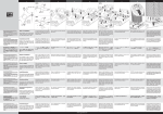
SmartLevel
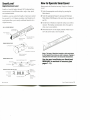
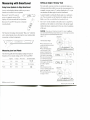
How to Operate SmartLevel
Digital Electronic Level
Measurements with SmartLevel are easy. Simply turn SmartLevel
on and:
SmartLevel reads all angles through 360,° displaying these
measurements in four different modes: angle, slope, pitch,
and simulated bubble.
In addition, you may select the SmartLevel precision needed
for your job. 0.1 or 0.2 degree resolution. And SmartLevel's
reset feature allows you to easily recalibrate SmartLevel to
original accuracy.
RAIL & SENSOR MODULE
1. Select the appropriate mode settings by pressing the
Mode button.
2. Select the appropriate Range by pressing the Hold and
Mode button (Shift-Range) at the same time (see pages 12
and 13).
3. Set the base of SmartLevel upon the surface you wish to
measure. The display automatically shows the angle in
clear, easy-to-use numbers.
4. Directional arrows on the display indicate which way to
move the rail to make it level or plumb.
Aircraft-Grade
Impact-Absorbing ,
Endcaps V
Removable Electronic
Sensor Module
Workglove-Sized
Handholds
SENSOR MODULE BACK
Locking Cams
Sensor Module
Locking Screws
9-Volt Battery Compartment
Notes: The base of SmartLevel module or rails must always
be flush against the surface you wish to measure. Tipping or
rolling the level will result in an inaccurate measurement.
Battery Compartment
Locking Screws
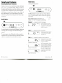
SENSOR MODULE FACE
Liquid-Crystal Display (LCD)
Mode Button ^
On/Off Button
^
88.3
=
PRO SMARTLEVEL
, Reset/Superset
Button
H H^*r Hold/Range
-~y
LIQUID-CRYSTAL DISPLAY (LCD)
Level Direction Indicator
Range Setting
Indicator
2 SmartLevel
n f t ft
Pitch Mode Indicator'
%A
You also must recalibrate your SmartLevel
REGULARLY to maintain its accuracy (see
pages 7-11).
Button
Degree(°)
& Slope {%)
Mode Indicator
:iK
Hold Mode
Indicator When
Flashing
How to Operate SmartLevel 3
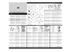
SmartLevel Features
Mode Button
Selecting SmartLevel Functions
Choosing the Measurement
SmartLevel is easy to use. Each button controls the feature
that's written on it (ON/OFF, MODE, RESET, and HOLD).
In addition, the Mode button works like a shift key to access
two other features. Simultaneously press Mode and Hold
(Shift-Range) to change Range settings. Or press Mode and
Reset (Shift-Superset) to activate SuperSet. These shift
functions are printed on the module just below their respective buttons.
The Mode button is used to select any of four different
ways of measuring angles: degrees, slope, pitch and simulated bubble.
PRESS
On/Off Button
When the Mode button is held down, the
display will "scroll" through all mode settings.
It c
PRO SMARTLEVEL
Degrees (°) — measured in tenths of one degree
33
C.C
MODE
Shift
PRO SMARTLEVEL
To activate SmartLevel, press the On/Off button. SmartLevel
will display the current angle in the Mode and Range last
selected.
To conserve power, turn off SmartLevel when your job is
completed. But if you forget. SmartLevel shuts off automatically if it is not jostled or moved within five minutes.
Indicates degree of inclination.
0.0° is level; 90.0° plumb. Used
to determine an existing angle or
establish a new one.
Slope (%) — measured in tenths of one percent
1
T
1.3 * A
Indicates percent slope. Used to
check drainage lines, landscaping grades, etc.
Pitch (IN/FT) — measured in fractions of one inch per foot
Indicates pitch or inches of rise
per foot of run. Used to establish
roof pitch, drainage, etc.
Just under 1/4 inch per foot
Just over 1/8 inch per foot
The Pitch mode reads in 1/8 inch
per foot increments. Pluses and
minuses are used to indicate when
the pitch is slightly more (+) or
less (-) than the angle shown on
the display. The Range setting
(accuracy level) does not affect
the Pitch mode.
Exactly 1/8 inch per foot
4 SmartLevel Features
SmartLevel Features 5
Pitch (continued)
Reset/SuperSet Button
In Pitch mode, SmartLevel measures from level (or
0:12) to 76° (or 48:12). After 76? SmartLevel measures deviation in inches per foot of run from vertical
(plumb). As a result, both level and plumb read "0"
on the display.
Recalibrating SmartLevel
For using SmartLevel on projects requiring metric
units, use the % slope mode to measure pitch. The
grade of an angle is equivalent to centimeters of rise
per meter of run.
Simulated Bubble (ci:i)
Indicates Sensor Module is
nearing level or plumb as bubble
moves closer to centerline.
Out of level
Closer
Perfectly level
The sensitivity of the bubble's
movement on the display is controlled by the Range(accuracy)
setting, with "1" being more sensitive than "2" Changing to the
Degree(°) Mode will allow you to
see how far off level and plumb
you are using numbers.
PRO SMARTLEVEL
This button is the key to keeping your SmartLevel accurate.
No level can withstand the abuses of a construction site without losing accuracy over time, but with SmartLevel you can
recalibrate to factory specs quickly and easily.
There are two procedures that you will use to do this: Reset
and Superset
• Reset is a simple "end-for-end" procedure you should use
daily before you begin working. It takes less than 30 seconds
to perform.
• SuperSet recalibrates SmartLevel through its entire 360°
range. It's an eight-step procedure that takes just a couple of
minutes.
Because SmartlLevel is digital, you can easily determine if
it's reading correctly —just compare numbers in a simple
"end-for-end" test — not unlike what you do with a bubble
level to make sure it's okay.
Use this diagnostic test daily to see if you need to Reset or
SuperSet your SmartLevel.
• Lay your SmartLevel on a clean, flat surface. (It doesn't have to be exactly
level.) Wait 10 seconds, and note the angle on the display.
• Rotate the level end-for-end so the display is on the opposite side. Be
sure and set SmartLevel in exactly the same spot, and allow it to sit for at
least 10 seconds before reading the angle again.
• If your measurements vary by more than 0.1°— which can be caused by
surface irregularities — you should Reset.
6 SmartLevel Features
SmartLevel Features 7
Reset
Reset is a simple 30 second, two-step pmcedure tlwt should be
done once a day, or whenever the module is reinstalled in
the rail.
Now that you've Reset your SmartLevel, try the same "endfor-end" in the vertical (plumb) position, making sure to wait
at least 10 seconds after inverting the level each time. If
these readings are different from each other by more than
0.1? then you need to SuperSet.
How to Reset
Turn on SmartLevel and place it on a flat surface. The
surface doesn't have to be level.
Note: Wait 15 seconds before pressing the Reset button.
Reset—Step 1
•Sensor Module faces you
• Broad base of rail on a flat surface
•Align with an edge or line
•Wait 15 seconds
• Press Reset button, hold until flashing
"CAL 1" symbol appears briefly, followed
by flashing angle measurement
Reset—Step 2
• Rotate SmartLevel 180° so that Sensor Module faces away from you
• Align with same edge or line
•Wait 15 seconds
• Press Reset button, hold until "CAL 2" appears
Superset
SuperSet recalibrates SmartLevel through its entire 360°
range. It is similar to Reset, but is done in four horizontal
and four vertical settings. You should SuperSet your
SmartLevel frequently, especially if it's taken a fall, or if
you 're using it in a very different temperature range from
when it was last Superset.
How to Perform SuperSet
Turn on SmartLevel and place it on a flat surface. You can
use any horizontal surface within 10° of level and any vertical surface within 10° of plumb to perform SuperSet. You
must use the same surfaces throughout the entire process.
Note: Each time you reposition SmartLevel during SuperSet, wait a
minimum of 10 seconds before pressing the Reset button. For optimal
accuracy, SuperSet should be performed with the Sensor Module placed
within a rail. If a rail is not available, you may perform SuperSet with the
Sensor Module alone.
Starting SuperSet
• Press and hold the Mode
and ftese/(Shift-Superset)
buttons simultaneously.
• Release the buttons when
the symbol "SUP" appears.
A "0" with flashing brackets will
then appear.
Press Simultaneously
Superset Begins
r n ~<
u _»
"0" Within
Flashing Brackets
8 SmartLevel Features
SmartLevel Features 9
SuperSet — Horizontal Settings
r
SuperSet — Vertical Settings
•Sensor Module tes you
•Broad base of rail on surface
•Align with an edge or line
•Wait 10 seconds
•Press Reset button until "[1]"
with flashing brackets appears
• Place SmartLevel against vertical suface so
that Sensor Module faces you
• Broad base of rail on surface
•Align with an edge or line
•Wait 10 seconds
• Press Reset button until "[5]" with flashing
brackets appears
L. C -.»
• Rotate SmartLevel so that Sensor
Module faces away from you
• Broad base of rail on surface
•Align with same edge or line
•Wait 10 seconds
•Press Reset button until "[2]"
with flashing brackets appears
• Flip SmartLevel so that narrow
top of the rail is on the surface and
Sensor Module faces you
• Align with same edge or line
•Wait 10 seconds
• Press Reset button until "[3]"
with flashing brackets appears
• Flip SmartLevel over so the narrow top of
rail is against vertical suface and Sensor
Module faces away from you
•Align with same edge or line
•Wait 10 seconds
• Press Reset button until "[6]" with flashing
brackets appears
r ~< ~<
»_ < -.<
• Rotate SmartLevel end-for-end so the narrow
top of rail is against vertical suface and Sensor
Module faces you
•Align with same edge or line
•Wait 10 seconds
• Press Reset button until "[7]" with flashing
brackets appears
i: 8 :i
• Rotate SmartLevel so that Sensor
Module faces away from you
• Narrow top of rail on surface
•Align with same edge or line
•Wait 10 seconds
•Press Reset button until "[4]"
with flashing brackets appears
The horizontal settings of SuperSet
are now completed.
• Flip SmartLevel over so the broad base of
rail is against vertical suface and Sensor
Module faces away from you
•Align with same edge or line
•Wait 10 seconds
• Press Reset button until "[8]" with flashing
brackets appears
Your SmartLevel has been SuperSet
back to factory-perfect accuracy.
Canceling SuperSet
You may cancel SuperSet procedure at any time during the
process by turning the unit off.
10 SmartLevel Features
SmartLevel Features 11
Hold/Range Button
Range—Choosing Accuracy
Freezing a Reading and Choosing Accuracy
Different jobs require different levels of accuracy. By pressing the Mode and Hold (Shift-Range) buttons simultaneously, you can select one of two range settings (0.1° or 0.2°) in
all but the pitch mode.
Range
Symbol
Hold
Symbol
PRO SMARTLEVEL
Hold—Freezing a Reading
If you need to take a measurement
with SmartLevel in an unreadable
position, or if you need to temporarily lock in a reading while you record it, simply press the
Hold button while SmartLevel is reading the angle that you
are measuring. The readout will freeze and a flashing "H"
will appear on the right side of the display. To release, press
the Hold button a second time.
Another advantage offered by the Hold button is that you
can change from one mode to any other while the angle
you've measured remains "frozen". This way you can convert an angle measured in one mode (such as degrees) to
another mode (% slope or roof pitch) without having to consult a conversion chart. You can also change the range (accuracy level) while a measurement is on hold.
12 SmartLevel Features
Each simultaneous press advances the range setting, which
appears on the middle left side of the display. The current
range setting is always displayed.
Hold/Range Button & Display
Range "1"
Accurate to within plus or minus
i} 1/10 (.1) of a degree; the
symbol "1" will appear on the
display
Range"2"
Accurate to within plus or minus
(+) 2/10 (.2) of a degree; the
symbol "2" will appear on the
display
SmartLevel Features 13
Measuring with SmartLevel
Setting an Angle ("Zeroing" Out)
For some jobs, you may wish to set a particular angle as a
reference point from which you can take measurements. For
example, you may want a 3° surface displayed as 0° so you
can measure all other angles from this benchmark.
Using Arrow Symbols to Align SmartLevel
Arrows on the display indicate which way to move
SmartLevel to achieve level or plumb.
i
Between 0° and 44.9,° a pair of
3
c
.9
arrows in opposite corners of the
display will point towards the level position.
o
T
A good example is setting the blade angle on a radial-arm
saw. You can easily use the SmartLevel module to set the
blade even if the saw table/bed isn 't perfectly level.
Just "zero" out the module on the table (set it to read 0.0°),
and then use the module to set the blade at the proper angle
without having to compensate for the out-of-level condition
of the saw.
Between 45° and 89.9° the arrows will point
towards plumb.
The SmartLevel display electronically "flips over" when the
unit is turned upside-down, allowing for easy reading when
measuring overhead components.
CAUTION: If you set your SmartLevel to read 0.0° when it is off level,
you must follow the Reset procedure before you can once again accurately
read level and plumb (see Reset/SuperSet button,
7-11).
with Module
Facing You
How to Set an Angle
Measuring Level and Plumb
The following table shows the display readings for each of
SmartLevel's four mode settings at 0.0° 45.0° and 90.0°:
Level
Plumb
Degrees
% Slope
Pitch (IN/FT)
0.0°
0.0%
0.0
45.0°
100%
12
90.0°
0.0%
0.0
14 Measuring with SmartLevel
Simulated Bubble
Out of range
Cl
• Place SmartLevel on the
surface you wish to set at 0.0'
Wait 10 seconds.
• Press the Reset button
until the symbol "CAL1"
appears, followed by the angle measurement itself.
r >l<
It will blink on the display.
•Do not turn the level 180°
as in the Reset procedure,
but instead press the Reset
button again, until the symbol "CAL2" appears.
That's it!
When the level is on this
surface or another at the same
angle, it will read "0.0°"
• To reset SmartLevel to true level
see pages 7 and 8.
Measuring with SmartLevel 15
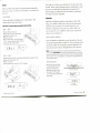
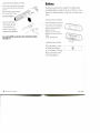
Integrated Wall Stand-Offs
Using the Sensor Module
with Various Rail Lengths
Scribing Lines with SmartLevel
SmartLevel's integrated wall stand-offs stabilize the tool for
scribing or measuring lines on vertical surfaces.
To extend the stand-offs, press and slide your thumb over the
ribbed portion toward the top of the rail. The stand-offs will
pivot out of their nested position.
The bottom surface of SmartLevel can now be easily used to
guide a pencil or scribe when drawing or measuring lines.
The Sensor Module may be used alone as a torpedo-style
level, or it can be transferred and locked into various rail
handholds. It fits into any handhold of the 48- and 78-inch
rails, but only into the center handhold of the 24-inch rail.
Longer rail lengths provide greater accuracy over longer
distances because they "average out" surface imperfections
(knots, blisters, bends, bows, etc.).
Grooved Cams
Waii
Why are SmartLevel Rails
Shaped Like a Triangle?
SmartLevel evolved from several hundred hours of consumer
testing and research dedicated to developing a new ergonomic
(comfort- and safety-oriented) design for SmartLevel.
The triangular shape, with its broad base and narrow top, permits
SmartLevel to be placed securely on a flat surface, preventing the
tool from easily tipping over or falling, while its narrow top makes
it easy to grip. The groove on the rail base allows you to set
SmartLevel more securely on a rounded surface, such as a
drainage pipe. And the beveled ends permit you to easily maneuver the tool into tight, angled spots, which would be impossible
with a typical rectangular level.
Finally, we added large handholds for the entire rail length, allowing you to get a firm, safe grip on your SmartLevel, even \ work gloves.
16 Measuring with SmartLevel
Transferring the Sensor
Module between Rails
The Sensor Module locks into the
handholds via a pair of grooved,
self-centering cams, which secure it
in the rail. The cams are engaged
or released by turning the two
locking screws located on the
back of the module.
Removing the Sensor Module from a Rail
• Using a screwdriver, turn each locking screw
counter-clockwise until the flat side of the screw
aligns with the top edge of the Sensor
Module. The flat side of the screw corresponds with a flat side of the cam.
• Firmly push the module out of
the handhold.
Flat on Top
of Screw
Matches Flat
of Cam
DO NOT FORCE.
• If the module does not slip out with reasonable
pressure, the cams may still be engaged.
Use the screwdriver to turn the cams
while pushing the module out.
Using Various Rail Lengths 17
Installing the Sensor Module into a Hail
• Slip the Sensor Module into the handhold
until its surfaces are flush with the surfaces
of the rail.
• Turn the locking screws clockwise
with a screwdriver until snug.
DO NOT FORCE.
Battery
SmartLevel is powered by a standard 9-volt battery. Each
new alkaline battery should provide up to 360 hours of continuous use. Lithium batteries will provide even more hours
of use.
Installing or Removing Battery
Excessive resistance
when turning the lock
screws indicates the
module is not correctly
centered in the handhold.
Don't forget to RESET your SmartLevel after reinstalling the module.
(See pages 7-11)
• Unscrew the battery compartment
cover screws. The two screws are
"captive" and do not separate from
the battery compartment cover.
• Remove the cover.
• Install or remove the battery.
• Replace the cover and snug the
screws.
DO NOT OVERTIGHTEN.
Low Battery Power Indicator
When the battery is weak,
the SmartLevel displays
the "Low Battery" warning.
Replace the battery when
this warning appears.
18 Using Various Rail Lengths
ill
Battery 19
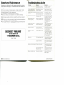
SmartLevel Maintenance
Troubleshooting Guide
SmartLevel is designed for the rugged construction environment, and the following tips will ensure that your SmartLevel
is kept in top condition.
Problem
Reason
Solution
SmartLevel does not turn on.
Battery dead or battery
connections are not tight or
have become disengaged.
Check battery connections.
See Battery, page 19.
SmartLevel does not automatically shut off after five
minutes.
Sensor Module is being
moved or jostled.
Keep unit stationary for five
minutes or more; or turn module off using On/Off button.
SmartLevel does not measure
accurately.
SmartLevel has not been re- See Reset Button, pages 7-11
calibrated recently, or has not and follow appropriate Reset
been recalibrated correctly.
and SuperSet steps closely.
Reset button does not work.
Not pressing Reset button for Push Reset button down until
a sufficient time.
the display reading changes.
See Reset Button, pages 7-8.
Difficult to select desired
mode or range setting.
Mode or Hold/Range button
is being pressed too long.
Release button as soon as
desired setting appears.
See Mode Button, page 5-6;
or Hold/Range Button,
pages 12-13.
Display reading "jumps" or
changes too easily.
SmartLevel is set on a toosensitive range setting.
Use the Hold/Range button to
set a less-sensitive range
setting. See Hold/Range
Button, pages 12-13.
Display keeps flashing.
The Reset button has
accidentally been pressed.
Press the Reset button again
or turn SmartLevel off. Repeat
the Reset procedure.
Display reads "ERR" or
"CAL".
Software diagnostics code
Turn the module off, then on.
If display continues to read
"ERR" or "CAL", replace battery. If display still continues
to read "ERR" or "CAL", call
SmartLevel Customer Service
at 1-800-762-7853.
3j';0" SilCKS
Dirt lodged between button
Hold module with display facand Sensor Module housing. ing downward. Press button
repeatedly to dislodge dirt.
Module slips out of the rail.
Cams are not turned to
properly lock the rail.
See Transferring the Sensor
Module between Rails, pages
17-18, and follow the steps
closely.
Module cannot be removed or Cams are not properly
difficult to remove from rail.
positioned.
See Transferring the Sensor
Module between Rails, pages
17-18. and follow the steps
closely.
• The Sensor Module and rails are weather- and water-resistant. Should
your SmartLevel be splashed with mortar or other construction site
residue, simply wipe clean with a damp cloth.
DO A/OHMMERSE THE SENSOR MODULE IN WATER.
• Aluminum surfaces can be cleaned with a non-abrasive cleansing
powder.
• ABS composite surfaces should be cleaned with a mild liquid soap and
water.
• We advise you to store your SmartLevel away from extreme temperatures
below -20°C (-4°F) or higher than 60°C (140°F).
• Don't forget to RESET your SmartLevel daily, and to use the simple "endfor-end" test frequently to see if SUPERSET is required.
QUESTIONS? PROBLEMS?
Feel free to call us at
1-800-SMARTLEVEL
(762-7853)
Battery compartment cover
does not come off.
20 SmartLevel Maintenance
Dirt lodged between Sensor
Module and rail.
Take fine-gauge wire and run
it between module and rail to
remove dirt.
Screws not completely
disengaged.
Unscrew more thoroughly.
Follow procedures under
Battery, page 19.
Troubleshooting Guide
WEDGE
I
N
N
O
V
A
T
I
O
N
S
Wedge Innovations
2040 Fortune Drive, Suite 102
San Jose, California 95131 -9799
Phone: 1-800-SMARTLEVEL (762-7853)
© 1992 Wedge Innovations. Wedge Innovations, SmartLevel, Smart Tools and Superset are registered trademarks
ol Wedge Innovations. Patent No 4,912,662; Des. 308.644.
28-00682-001 Rev. A