1
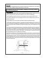
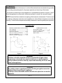
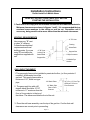
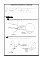
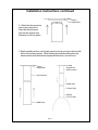
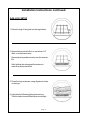
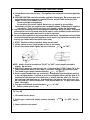
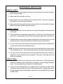
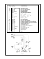
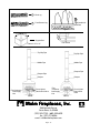
Malm Fireplaces, Inc.
368 Yolanda Avenue
Santa Rosa, Ca 95404
(707) 523-7755 - Fax: (707) 571-8036
Fire Drum GF-2/GF-3
ANSI Z21.50-1996
Assembly And Installation Instructions
LEAVE THESE INSTRUCTIONS WITH THE OWNER.
Listed Vented Gas Fireplace
FOR YOUR
SAFETY
FOR YOUR SAFETY
WHAT TO DO IF YOU SMELL GAS
Do not store or
use gasoline or
other flammable
vapors and liquids in the vicinity of this or any
other appliance.
Do not try to light any appliance.
Do not touch any electrical switch; do not use
any phone in your building.
Immediately call your gas supplier from a neighbor's phone. Follow the gas supplier's instructions.
If you cannot reach your gas supplier; call the
fire department.
WARNING: Improper installation, adjustment, alteration, service or
maintenance can cause injury or property damage. Refer to this
manual. For assistance or additional information consult a qualified
installer; service agency or the gas supplier.
GENERAL INFORMATION
This appliance has been tested in accordance with National Safety Standards and
for installation and operation as described in this manual.
Please read all the instructions before beginning your installation. Check with your local building
code agency to ensure compliance with local codes. In the absence of local codes the installation
must comply with National Fuel Gas Code ANSI Z223.1- current edition.
Installation and repair should be done by a qualified service person. The appliance
should be inspected before use and at least annually by a professional service
person. More frequent cleaning may be required due to excessive lint from
carpeting, bedding material, etc. It is imperative that control compartments,
burners and circulating air passageways of the appliance must kept clean.
Do not use this appliance if any part has been under water. Immediately call a
qualified service technician to inspect and replace any part of the control system
that has been under water.
Unpack all parts from cartons carefully inspecting all parts. If any parts are
damaged or missing, contact shipper or dealer immediately.
Do not install this appliance using damaged parts.
GAS SUPPLY
For use with natural gas or propane gas, depending on which option you have ordered. The
minimum inlet gas supply pressure for the purpose of input adjustment:
Natural = Minimum 5" Water Column
Maximum 10.5" Water Column
Propane = Minimum 10" Water Column
Maximum 13" Water Column
a. The supply system should include a manual shut-off valve and union in the line, so that
the heater can be disconnected for servicing.
b. The appliance and its individual shut-off valve must be disconnected from the gas
supply piping system during any pressure testing of that system at test pressures in
excess of 1/2 psig (3.5 kPa).
c. The appliance must be isolated from the gas supply piping system by closing its
individual manual shut-off valve during any pressure testing of the gas supply piping
system at test pressures equal to or less than 1/2 psig (3.5 kPa).
d. A 1/8 inch N.P.T. plugged tapping is provided, for test gauge connection, on the
elbow adjacent to the gas control valve.
Due to high temperatures, the appliance should be located out of
traffic and away from furniture and draperies.
Page - 2
VENTING
The unit is a vented gas fireplace and must be connected to a chimney/flue in accordance
with the code, using the chimney manufacturer's instructions.
This appliance must not be connected to a chimney flue servicing a separate
solid fuel burning appliance.
VENT DAMPER
This appliance is equipped with a factory installed vent damper device, located in the first
section (starter section) of pipe which attaches to the collar of the appliance.
Only this appliance may be served by the vent damper device supplied with this unit.
A 6" minimum clearance must be maintained between the vent damper device and combustible construction.
The vent damper device should be inspected annually by a qualified installer.
The thermally controlled vent damper is an energy saving device designed for installation in
vents of listed gas-fired appliances equipped with a draft hood. The damper saves energy
by preventing the escape of heated air through the venting system, when the appliance is not
in use.
It has four quadrants of bimetal which remain closed when the appliance is not in operation.
Upon ignition of the appliance, the hot flue gases reach the damper, causing the quadrants
to flex, thereby opening the vent passage within a short period of time. This internal flexing
of the bimetal is the only movement in the damper. No power supply or functional connection
with the appliance controls is required for operation.
Installation of vent dampers can increase the potential for condensation in oversized masonry
chimneys. This is due to poor thermal insulation of the chimney and reduced air movement
when the damper is closed. We recommend that masonry chimneys be lined with materials
such as Type B gas vent, aluminum or stainless steel to reduce the chance of condensation.
Most building codes, in fact, require the lining of chimneys when gas appliances are vented
into masonry chimneys.
Page - 3
CLEARANCES
Make sure that minimum clearances to combustible materials are maintained during installation including adequate space for the proper operation and servicing of the heater.
The minimum clearances from the appliance to combustibles are shown on figures 1 and 2.
Place the appliance on a flat, solid, continuous serface (i.e. wood, tile, concrete, metal).
NOTE: Ensure that the combustion air opening of the heater is not obstructed. Provision must
be made for adequate combustion and ventilation air, with sufficient clearances around the
opening. There must be adequate accessibility clearance for servicing and proper operation.
CLEARANCES
SIDEWALL AND BACKWALL INSTALLATION
Unit to Sidewall ------------------------------------ 3"
Unit to Backwall ----------------------------------- 3"
Connector to Sidewall --------------------- 141/2"
Center of Connector to Sidewall ------------ 19"
Connector to Backwall -------------------- 14 1/2"
Center of connector to Backwall ------------ 19"
CORNER INSTALLATION
Unit to Adjacent Walll --------------------- 3"
Connector to Adjacent Wall ------ 14 1/2"
Center of Connector to
Adjacent Wall ------------------------------ 19"
14 1/2"
14 1/2"
3"
3"
14 1/2"
14 1/2"
3"
45
3"
Figure 2
Figure 1
WARNING
Children and adults should be alerted to the hazards of high surface
temperature and should stay away to avoid burns or clothing ignition.
Young children should be carefully supervised when they are in the same
room as the appliance.
CAUTION
Any safety screen or guard removed for servicing an appliance must be
replaced prior to operating the appliance.
Clothing or other flammable material should not be placed on or near the
appliance.
Page - 4
Installation Instructions
Do Not Install In A Mobile Home
READ ALL INSTRUCTIONS CAREFULLY BEFORE
STARTING THE INSTALLATION.
1. Position unit to comply with the minimum clearances to combustible materials.
Minimum clearances are shown in figures 1 and 2. It is recommended that no
overhead cross members in the ceiling or roof be cut. Reposition unit if
necessary, being careful not to move closer than the minimum clearances.
VENTING REQUIREMENTS
Use a masonry, "B" vent
or class "A" chimney.
Follow all manufacturers'
requirements and local
building codes. If you are
using "B" vent utilize the
support box supplied with
unit.
8" "B"-Vent
Framing
Sheet Rock
8" "B"-Vent
Locking Tab
Starter Band
Support Box
9" Slip Connector
Support Box
9" Middle Pipe
Section
GAS LINE ATTACHMENT
1. The gas supply line must be installed to penetrate the floor, (or floor protector if
required), at the center-line of the
gas unit. This supply line must be a
minimum of 1/2", black iron type
1/2" Black Elbow
10 1/2" to 11" From Top
pipe.
1/2" Black Pipe
2. The gas supply line with a 90
Floor or Floor
degree elbow should be 10 1/2"
Protector
minimum to 11" maximum from the
floor or floor protector to the top of
the elbow. The elbow must face the front of the unit.
Of Elbow To Floor or
Floor Protector
3. Place the unit base assembly over the top of the gas line. Confirm that wall
clearances are correct prior to proceeding.
Page - 5
Installation Instructions continued
4. Lift the control cover. Using a 1/2" x 8" nipple, extend the gas supply line to the front
of the unit.
5. Attach gas supply shut-off valve part # GF-1A to the supply line.
6. Connect 3/8" x 12" flex connector part # GF-1B to the shut-off valve.
7. Make certain the gas valve is closed. Turn on gas supply and test for leaks using a
soapy water solution.
1. ASSEMBLE UNIT.
GF2
A. Place the body section into the base. Align the opening with the control cover.
B. Place the hood over the body section.
GF2 Body
GF2 Base
Fit body Into
Groove In Base
Assembly
Body Front Opening
Control Cover
Front of unit
GF3
A. Place the hood into the base. Align the opening with the control cover.
Hood
GF3 Hood
Fit Hood Into
Groove In Base
Assembly
Base
Assembly
Front of Hood Opening
Control Cover
Front of
Base
Assembly
Page - 6
Installation Instructions continued
Ceiling
Support Box
2. Attach the slip connector
pipe to the support box.
Insert the slip connector
pipe into the support box
and twist to lock into place.
3. Slip the middle section over the slip section only far enough to allow installation of the starter section. While holding the middle section place the
starter section with the thermal damper at the bottom, into the hood.
Ceiling
Support Box
Ceiling
Support Box
Slip Connector
Slip Connector
Middle Pipe
Damper Pipe
Damper
Fit Into Hood
Middle Pipe
Page - 7
Installation Instructions continued
GAS LOG SETUP
1. Place the legs of the grate into the leg holders.
2. Spread the vermiculite first, no more than 1/4"
thick, over the burner area.
Spread glowing embers evenly over the vermiculite.
After lighting the unit spread the embers to
acheive an even coal effect.
3. Place fire logs as shown, using alignment knobs
on the logs.
4. Light the pilot following lighting instructions.
Turn the valve to on and the burner should light.
Page - 8
OPERATING INSTRUCTIONS
A. Follow these instructions exactly. This appliance has a pilot which must be lighted by
hand.
B. BEFORE LIGHTING smell all around the appliance area for gas. Be sure to smell next
to the floor because some gas is heavier than air and will settle on the the floor.
WHAT TO DO IF YOU SMELL GAS
Do not try to light any appliance.
Do not touch any electric switch; do not use any phone in your building.
Immediately call your gas supplier from a neighbor's phone. Follow the gas supplier's
instructions. If you cannot reach your gas supplier, call the fire department.
C. Use only your hand to push in or turn the gas control knob. Never use tools. If the knob
will not push in or turn by hand, don't try to repair it, call a qualified service technician.
Force or attempted repair may result in a fire or explosion.
D. Do not use this appliance if any part has been under water. Immediately call a qualified
service technician to inspect the appliance and to replace any part of the control system
and any gas control which has been under water.
1. STOP! Read the safety information above on this label.
2. Lift the control access panel located in front of the screen.
3. Push in the control knob slightly and turn clockwise
Control Valve
to "OFF".
Pilot Assembly
NOTE: Knob cannot be turned from "PILOT" to "OFF" unless knob is pushed in
slightly. Do not force.
6. Wait five (5) minutes to clear out any gas. If you smell gas, STOP! Follow "B" in the
safety information above on this label. If you don't smell gas, go to the next step.
7. Turn knob on gas control counterclockwise
to "PILOT."
8. Push in control knob all the way and hold in. Immediately light the pilot by pushing
in the red lighter button. Continue to push the red lighter button until the pilot is lit.
Continue to hold the knob in for about one (1) minute after the pilot is lit. Release
the knob and it will pop back up. If the knob does not pop up, turn off the gas shut
off valve and call a service technician. Pilot should remain lit. If it goes out, repeat
steps 3 through 8.
9. Turn gas control knob counterclockwise
to "ON."
10. Lower control access panel.
To Turn Off
1. Lift control access panel.
2. Push in gas control knob slightly and turn clockwise
force.
3. Lower control access panel.
Page - 9
to "OFF." Do not
MAINTENANCE INSTRUCTIONS
GENERAL SAFETY
1. Always shut off the gas supply and make sure that the heater is cool before starting
any servicing operation.
2. Always check for leaks after servicing.
3. Always check for correct combustion and ventilation air flow. The flow of combustion
and ventilation air must not be obstructed.
4. Always check that the appliance area is clear and free from combustible materials,
gasoline, and other flamable vapors and liquids.
PERIODIC CHECKS
1. Keep the burner and control compartment clean by brushing and vacuuming at least
once a year.
2. The flame patern should be checked periodically. The flame color should be blue with
yellow tips. If needed adjust the air shutter to provide a proper flame. See Figure F.
3. A qualified service person should Inspect the appliance vent system prior to use and
at least annually, to ensure that the flow of combustion air is not obstructed.
4. If you are unsure how to perform these maintenance procedures have a qualified field
service person check the unit at least annually.
NOTE: During the first few fires the odor of paint or oils remaining from manufacturing are
likely to release an odor. This is normal and will stop as soon as the paint has curred.
4. If for any reason a log should break it must be replaced with the same log. See the log
diagram for the exact replacement log needed. The position of the logs must be as
shown in the diagram.
CARE OF FINISH
1. The matte black finish can be wiped clean with a damp cloth. If the finish becomes
marred or scratched it may require touch up spraying. Use Stove Bright Flat Black
spray. This is available from your dealer or from Malm direct.
2. If your unit is porcelain enamel use any glass cleaner to wipe the unit clean. Minor
scratches can be polished with most non-abrasive auto polish. If the porcelain should
become chipped or severly damaged an enamel touch up is available from your dealer
or Malm direct.
Page - 10
ITEM PART NO.
1-A
1-B
1-C
2
3
4
5
6
7
8-A
8-B
8-C
9
9
10
11
12
13
14
15
16
17
DESCRIPTION
GF-1A-B3812-VIM
GF-1B
GF-1C
GF-2-RV20
GF-3
GF-4-J-100A
GF-5
GF-6
GF-7-219-3/8
GF-8A
GF-8B
GF-8C
GF-9-42
GF-9-53
GF-10
GF-11
GF-12
GF-13-Mark21
GF-14
GF-15-MBT
GF-16
GF-17
Gas Shut Off Valve
3/8" x 12" Flex Connector
3/8" Fitting - Brass
Pressure Rgulator
Gas Valve Mounting Bracket
Gas Control Valve
3/8" x 1 1/2" Black Nipple
3/8" - 90 Degree Elbow - Black
1/8" M.I.P. Plug - Black
3/8" Fitting - Brass
3/8" Fitting - Brass
3/8" x 18" Flex Connector
Air Shutter Assembly With Orifice Natural
Air Shutter Assembly With Orifice Propane
Thermocouple Tube 18"
Pilot Supply Tube 18"
Piezo Lighter Mounting Bracket
Piezo Lighter
Piezo Lighter Wire 18"
Lighter Electrode
Thermocouple
Pilot
15
16
17
11
10
8-C
1-A
14
8-A
1-B
5
13
1-B
2
3
4
Page - 11
6
7
12
1
Rear Log
2
Front Bottom Log
Adjustable Air
Shutter
Figure F
12 3/4"
12 3/4"
Support Box
Pilot Flame
Frame In 13" x 13"
Top Slip Pipe
Top Slip Pipe
Middle Pipe
Middle Pipe
Damper Pipe
Damper Pipe
Damper
Damper
Piezo Lighter
Gas Control Valve
Flex Connector
Gas Supply
Line
Flex
Connector
Gas Supply
Line
GF-2
Piezo Lighter
Gas Control
Valve
GF-3
Malm Fireplaces, Inc.
368 Yolanda Avenue
Santa Rosa, Ca 95404
(707) 523-7755 - (800) 535-8955
Fax: (707) 571-8036
email: [email protected]
Page - 12