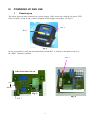
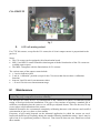
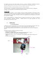
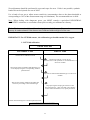
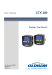
1
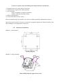
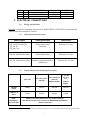
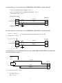
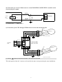
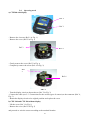
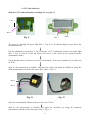
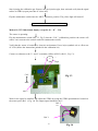
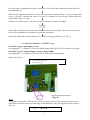
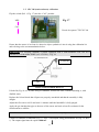
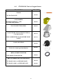
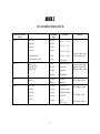
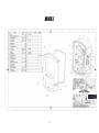
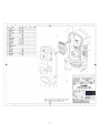
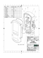
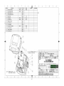
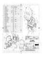
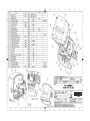
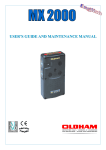
300 SERIES LEL DETECTOR DETECTOR-TRANSMITTER FOR COMBUSTIBLE, TOXIC GASES AND OXYGEN O P ER A T IO N A N D M A IN T EN A N C E M ANUA L Ref.: NP300 GB Revision G GAS DETECTION Thank you for purchasing an INDUSTRIAL SCIENTIFIC instrument. We appreciate your business. We trust that our commitment to the technical excellence of our products will ensure your complete satisfaction. Please read the following document carefully. LIM I TATI ON OF LI ABI LI TY * INDUSTRIAL SCIENTIFIC will not be liable under any circumstances for material losses, personal injury or death resulting in whole or in part from the inappropriate use of this equipment, the installation or storage of this equipment not in conformance with the instructions and warnings presented in this manual and/or not in conformance with current standards and regulations. * INDUSTRIAL SCIENTIFIC neither allows nor authorizes any other company, individual or legal entity to make any claims as to the liability of INDUSTRIAL SCIENTIFIC, even if said company, individual or legal entity is directly involved in the sale of INDUSTRIAL SCIENTIFIC products. * In no event will INDUSTRIAL SCIENTIFIC be liable for any direct or indirect damage including those resulting from the sale and the use of its products IF THOSE PRODUCTS WERE NOT SPECIFIED AND SELECTED BY INDUSTRIAL SCIENTIFIC FOR SUCH USE. O WN ER S H I P C L A US ES * The images, blueprints, specifications and information contained in this document belong to INDUSTRIAL SCIENTIFIC. * This information may not be physically, electronically or otherwise reproduced, copied, disclosed or translated, either in part or in whole, or used in the manufacturing or sale of INDUSTRIAL SCIENTIFIC equipment, nor for any other reason without prior permission from INDUSTRIAL SCIENTIFIC. WARN INGS * This document is not contractual. On behalf of its clients, INDUSTRIAL SCIENTIFIC reserves the right to modify the technical characteristics of its equipment without notice to improve product performance. * CAREFULLY READ THIS DOCUMENT BEFORE USING THE PRODUCT: this document should be carefully read by any individual who has or who will have the authority to use, maintain or repair this equipment. * Any and all warrantees and performance claims will only be valid if the equipment is operated, maintained and repaired in accordance with INDUSTRIAL SCIENTIFIC directives, by INDUSTRIAL SCIENTIFIC personnel or by personnel appointed by INDUSTRIAL SCIENTIFIC. WARR AN TY * Two-year return to factory warranty under normal operating conditions on parts and labor, consumable materials excluded (sensors, filters, etc.) 3 CONTENTS I. INTRODUCTION............................................................................................................................5 1. 2. General Information .....................................................................................................................5 Composition .................................................................................................................................5 II. INSTALLATION AND CONNECTIONS........................................................................................5 1. INSTALLING THE DETECTORS ................................................................................................5 1.1 Layout...................................................................................................................................5 1.2 Mechanical installation...........................................................................................................6 2. ELECTRICAL CONNECTIONS...................................................................................................7 2.1. Wiring specifications ..............................................................................................................7 2.2. Cable glands and cable types ..................................................................................................7 2.3. Connections for the various types of sensors.............................................................................7 2.4. Operating mode....................................................................................................................10 III. POWERING UP AND USE..........................................................................................................11 1 2. Powering up................................................................................................................................ 11 4-20 mA analog output ................................................................................................................ 12 IV. MAINTENANCE..........................................................................................................................12 1. Calibration ................................................................................................................................. 13 1.1. Recommendations.................................................................................................................13 1.2. CEX 300 calibration .............................................................................................................14 1.3. CTX 300 calibration .............................................................................................................15 1.4. COX 300 Calibration, “OXYGEN” type.................................................................................17 1.5. CSC 300 (semiconductor) calibration ....................................................................................18 1.6. CTX300 CO2 calibration.......................................................................................................19 1.7. CTX300 CO2 Linearization card...........................................................................................20 2. Replacing a sensor....................................................................................................................... 26 3. Disposal...................................................................................................................................... 26 4. Replacement Parts List ................................................................................................................ 26 4.1. CEX 300-type Combustible Sensor.........................................................................................26 4.2 CTX/COX 300 Toxic or Oxygen Sensor..................................................................................28 4.3 CSC300 Semiconductor Sensor..............................................................................................30 4.4 CTX300 CO2 Sensor.............................................................................................................30 V. PARTICULAR SPECIFICATIONS FOR USE IN EXPLOSIVE ATMOSPHERES IN ACCORDANCE WITH THE EUROPEAN ATEX 94/9/CE DIRECTIVE............................................31 1. SPECIFICATIONS FOR MECHANICAL AND ELECTRICAL INSTALLATIONS IN EXPLOSIVE ZONES..........................................................................................................................31 2. PERFORMANCE SPECIFICATIONS FOR THE CEX 300 EXPLOSIVE GAS DETECTOR ....31 2.1. 3 Technical Specifications and Particular Instructions for the CEX300 Explosive Gas Detector...32 MARKINGS:................................................................................................................................34 VI CERTIFICATIONS.......................................................................................................................35 ANNEX 1 ............................................................................................................................................39 ANNEX 2 ............................................................................................................................................41 ANNEX 3 ............................................................................................................................................42 4 I. INTRODUCTION 1. General Information 300 Series gas detectors are designed to measure combustible toxic gases or vapors and oxygen. With robust materials, a specifically-adapted design, appropriate accessories, INOX bolts, and a polyamide case (IP66) (IP55 for the CO2 version), 300 series detectors are designed to withstand the roughest conditions. . 2. Composition Sensor type CEX 300 Toxic Oxygen CTX 300 Semiconductor Gases detected Combustible gas Common toxic gases detected Oxygen Detection method Catalytic oxidation Type of sensor pack Explosion-proof sensor Electrochemical sensors 1 Pre-calibrated removable sensor pack2 Options Cable gland for flexible cable or armored cable3 Electrochemical sensor Pre-calibrated Removable sensor pack, removable sensor not pre-calibrated pack: 0-30% scale or 0-100% volume. With display Certification ATEX II 2GD 4 II. With display None - Combustible gas - Solvents - Some Freons Semiconductor sensor None None CO2 CO2 Infrared absorption Removable sensor pack Infrared column, not pre-calibrated None INSTALLATION AND CONNECTIONS For use in explosive atmospheres: in accordance with the European directive ATEX 94/9/EC, you must read the “Particular Specifications” paragraph. 1. INSTALLING THE DETECTORS 1.1 Layout While the measuring sensor is always located on the underside of the detector, several factors determine where the detector should be located: • If the gas being measured is lighter than the air, place the detector near the ceiling. • If the gas is heavier than the air (CO2 and Freons, for example) place the detector close to the floor. • Near offtake points. • Generally, in locations where gas may accumulate, taking into consideration both - the effects of temperature, and - the direction of winds. 1 Specific to each gas Choice between several scales 3 Requires grounding 2 4 EEx ed IIC T6 (-20 to 60°C) 5 Factors to consider when determining the best placement for the detector: ⇒ Potential sources for vapor and gas emissions ⇒ Characteristics of gases and vapors (density) ⇒ Air circulation - inside: mechanical or natural ventilation - outside: wind direction and velocity ⇒ Effects of temperature ⇒ Local constraints (air flow, water) Detectors should always be located in an easily accessible location for maintenance purposes. Special accessories may be necessary to protect the equipment against any liquid projectiles, dust, direct sunlight or low temperatures in the area. 1.2 Mechanical installation Method 1: wall- mounted Drilling diagram Method 2: ceiling- mounted 2 3 1 Same drilling diagram, support brace used 6 REF. 1 2 3 No. 1 4 4 DESCRIPTION CEX / CTX300 BRACE CHC LI2 SCREW A25 ACCD WASHER OFSA REF 6132380 6902218 6905518 MATERIAL INOX INOX . 2. ELECTRICAL CONNECTIONS 2.1. Wiring specifications If needed: consult the grounding instructions for INDUSTRIAL SCIENTIFIC instruments and related connection materials in Annex 1. 2.2. Cable glands and cable types Sensor types Cable gland type Cable entry CTX 300 (TOX and OX) CTX 300 SC CTX 300 CO2 Nickel-plated brass Neoprene Between 6–11 mm CEX 300 with shielded cable Nickel-plated brass Between 6–11 mm CEX 300 with armored cable 5 Double compression nickelplated brass Between 8.5–16 mm 2.3. Connections for the various types of sensors CEX 300 CTX 300 (TOX and OX) without display without display Output signal voltage 4-20 mA 4-20 mA 4-20 mA Number of wires 3 wires 3 wires 2 wires 3 wires Max. impedance (Z) of the line 5 CTX 300 (TOX and OX) CTX 300 SC and CO2 Refer to the characteristics for the central controller The CEX 300 sensor only connects to INDUSTRIAL SCIENTIFIC central controllers Here, the CEX 300 case is equipped with a grounding reclaim screw to connect the cable armor to the ground cable. 7 a) Connection of a 3-wire sensor to an INDUSTRIAL SCIENTIFIC central controller 1 wire (+) continuous power supply → No. 3 1 wire (-) continuous power supply (0 volt mass) → No. 2 1 output signal wire → No. 1 - Detector Control Unit + 24 Vcc 3 2 1 3 2 1 GND Signal b) Connection of a 2-wire sensor to an INDUSTRIAL SCIENTIFIC central controller - 1 wire (+) → No. 3 1 signal wire → No. 1 Formant la boucle de courant 4/20 mA sur 2 fils Detector Control Unit + 24 Vcc 3 2 1 Signal 3 2 1 c) Connection of a 3-wire CTX300 sensor to a non-INDUSTRIAL SCIENTIFIC controller and to an internal power supply. Control Unit« other » + 24 Vcc + Detector Power (1) GND R Signal (R) Maximum resistance = 200 Ω. (1) 15 = VCC = 32 18 = VCC = 30 for CO2 Max I: 130 mA 8 3 2 1 d) Connection of a 2-wire 4-20mA sensor to a non-INDUSTRIAL SCIENTIFIC controller and to an internal power supply. 24 Vcc (+) Control unit « other» + ALIM 3 2 1 (1) signal (1) 15<VCC<32V Detector Max I = 30 mA e) Connection of two CEX 300-type EXPLO sensors to the same measuring line (1) Sensor 1 1 2 3 4 1 2 3 Detector CEX 300 Nb1 4 Cable 3 wires CONTROL UNIT 3 2 1 3 2 1 4 Junction Box Ref. 6313539 3 2 1 (2) Sensor 2 1 2 3 4 Cable 4 wires Detector CEX 300 Nb 2 (1) and (2) Check to ensure that terminals 1 and 4 are not connected This only applies when the 2 sensors are located in the same room, protecting the same installation. 9 2.4. Operating mode a) CTX300 with display Ref. 2 Ref. 1 FIG. 1 - Remove the 4 screws (Ref. 1 in Fig. 1) - Remove the cover (Ref. 2 in Fig. 1) Rep33 Ref. Rep44 Ref. FIG. FIG 22 - Gently remove the screw (Ref. 3 in Fig. 2) - Completely remove the screw (Ref. 4 in Fig. 2) Ref. 5 Ref. 6 FIG. 3 - Turn the display circuit as shown above (Ref. 5 in Fig. 3) - Connect the cable (see 2-3: Connections for the various types of sensors) to the connector (Ref. 6, Fig. 3) - Return the display circuit to its original position and replace the cover b) CEX 300 and CTX 300 without display - Lift the cover (Ref. 1 in Fig. 1) - Remove the cover (Ref. 2 in Fig. 2) and proceed to wire the sensor according to the terminal location 10 III. POWERING UP AND USE 1 Powering up The sensor turns on when connected to a power supply. If the sensor has a display, the green LED will be lit (Ref 1 in Fig 4) and a value will appear on the display screen (Ref. 2 in Fig 4). Ref. 2 Ref. 1 Fig. 4 In case of a problem, verify that the maintenance switch (Ref. 1), located on the main circuit is in the “MES” (measure) position. Ref. 1 CIRCUITBOARD CTX 300 CAL MEAS CIRCUITBOARD CTX 300 SC Fig. 5 Fig. 6 Ref. 1 11 CO2 CIRCUIT Fig. 7 2. 4-20 mA analog output For CTX 300 sensors, except for the CO2 sensor, the 4-20 mA output current is proportional to the gas level. Notes: • The CO2 sensor can be equipped with a linearization board. • MX 15 and MX 32 central controllers that integrate with the linearization of the CO2 sensor are available upon request • The MX6 2 integrates with the linearization of CO2 sensors. The various states of the output current include: • ≤ 1 mA to indicate a fault • 2 mA in “calibration” position (except for the CO2 sensor that does not have a calibration function) • between 4 and 20 mA for measurement values • = 20 mA if levels exceed measurement range IV. Maintenance Warning: The adjustment operations in this paragraph are reserved for authorized, trained personnel because they may compromise detection reliability. Gas detectors are safety devices. In consideration of this, Industrial Scientific recommends regular testing of fixed gas detection installations. This type of test consists of injecting a standard gas of sufficient concentration into the sensor to set off the pre-adjusted alarms. This test does not, in any event, replace a full calibration of the sensor. Industrial Scientific also recommends completely calibrating detectors with a known and certified concentration of gas every three or four months. Frequency of gas testing depends on the industrial application in which the sensors are used. Inspection should occur frequently during the months following installation startup, later it may be spaced out if no significant problem is observed. Time intervals between tests should not exceed three months. 12 If a detector does not react upon contact with gas, it must be calibrated. Calibration frequency should be adapted based on test results. However, it should not be greater than one year. Industrial Scientific recommends using a test gas to calibrate detectors. The site manager is responsible for implementing the safety procedures on his site. Industrial Scientific is not respons ible for implementing safety procedures. The CEX 300 To reach a SIL Capability 1 level according to European standard EN50402, (requirement relative to the functional safety of fixed gas-detection systems), the maintenance period for explosive- gas detectors must be no more than six months. In SIL2 level installations, the maintenance period must be at most three months. These recommendations are compliant with the standards and directives for safety in industrial sites. Nevertheless, Industrial Scientific – Oldham shall not be held responsible for safety procedures put into effect on a site. 1. Calibration 1.1. Recommendations Calibration consists of adjusting the zero of the clean air sensor and adjusting sensitivity with a test gas. Adjustments are made at the sensor level or on the control unit (as for CEX 300). To adjust settings (ZERO and SENSITIVITY) on the control unit, refer to the notice displayed therein. Equipment needed to calibrate the detector correctly: - flexible plastic tubing (Ref. 1) - manometer + regulator valve for the compressed gas tanks (Ref. 2 – Fig. 8) - 0 to 601/h flow meter (if the tank is not equipped with one). - calibration pipe (Fig. 8 – Ref. 3), which may vary depending on the nature of the gas (see Annex) - one tank of test gas (Ref. 4) Ref. 2 Ref. 4 Ref. 1 Ref. 3 13 Fig. 8 Zero adjustment should be performed in a gas and vapor free area. If this is not possible, synthetic bottled air can be injected at a rate of 60l/h. Use a bottle of test gas to adjust sensor sensitivity (concentration close to the alarm threshold or corresponding to 30% of the measurement range at a minimum). The recommended rate is 60l/h. Note: When dealing with dangerous gases, you MUST consult a specialized INDUSTRIAL SCIENTIFIC technician or use another sensor pack recently pre-calibrated at a factory. Note: The detector should be calibrated using the intended flow-rate. The actual concentration of gas may be underestimated if the detector was calibrated with too high of a flow rate. IMPORTANT: For CEX 300 sensors , the calibration gas should contain 21% oxygen. 1.2.CEX 300 calibration PROCEDURE CONTROL UNIT DETECTOR Put the line in calibration mode Determine if the air is clean. If not, inject the sensor with synthetic or reconstituted air at a flow rate of 60l/h. Wait for the signal to stabilize and adjust the zero on the display using the corresponding “ZERO” potentiometer Inject the recommended calibration gas at a flow rate of 60l/h. Wait for the signal to stabilize and adjust the sensitivity according to the calibration gas Stop injecting the sample gas and remove the Gas injection pipe – Then wait and verify that the sensor returns to ZERO (if not, repeat procedure) Return the measuring line to normal operation mode CALIBRATION COMPLETE 14 1.3.CTX 300 calibration Method 1: CTX 300 with display (excluding O2 , see page 17) CAL Ref. 2 Ref. 1 Fig. 9 Ref. 3 The sensor is operating: the green light (Ref. 1, Fig. 10) is lit and the display screen shows the measurement level. Flip the maintenance switch (Ref. 2, Fig 9) into the “CAL” (calibration) position: the yellow light (Ref. 3, Fig. 10) will be lit and the sensor will send a 2 mA current to the central controller (maintenance mode). Verify that the sensor is located in a clean-air environment. If not, inject synthetic air at a flow rate of 30 l/h. Wait for the measurement to stabilize (displayed on screen) and adjust the ZERO by using the ZERO potentiometer located on the sensor pack. (Ref. 1, Fig. 11) Ref. 2 Ref. 1 Fig. 11 Fig. 12 Inject the recommended calibration gas at a flow rate of 30 l/h. Wait for the measurement to stabilize and adjust the sensitivity by using the sensitivity potentiometer located on the sensor pack. (Ref. 2, Fig. 11) 15 Stop injecting the calibration gas. Remove the gas injection pipe, then wait and verify that the signal returns to ZERO (repeat procedure if it does not). Flip the maintenance switch into the “MES” (measure) position. The yellow light will turn off. CALIBRATION COMPLETE Method 2: CTX 300 without display except for O2 – SC – CO2 The sensor is operating: Flip the maintenance switch (Ref. 13, Fig 5) into the “CAL” (calibration) position: the sensor will send a 2 mA current to the central controller (maintenance mode) Verify that the sensor is located in a clean-air environment. If not, inject synthetic air at a flow rate of 30 l/h (follow the instructions included in the calibration kit) Connect a voltmeter to the V+ and V- terminals (caliber mV/DC) (Re f. 1, Fig. 13). - V + Rep1 CAL Fig. 13 MES Ref. 5 Wait for the signal to stabilize and adjust the ZERO by using the ZERO potentiometer located on the sensor pack. (Ref. 1, Fig. 14) The output signal should be 0m V Ref. 2 (s) Ref. 1 (0) 16 Fig. 14 Now inject the recommended test gas at a flow rate of 30 l/h (use the calibration kit and follow all recommendations) Wait until the signal has stabilized, read the mV value on the voltmeter (Fig. 13, rep 1), with the full scale at 1600 mV, calculate the value to be read as a function of your test gas. Adjust using the potentiometer (Fig. 14, rep 2). Example: CO sensor scale 0-300 ppm / test gas injected at a content of 100ppm Reading 533 mV Shut off the calibration gas injection and withdraw the gas injection pipe. Then wait and check that the scale has returned to zero (otherwise repeat the procedure). Switch the maintenance on/off switch to the “MES” (measure) position (rep 5, Fig. 3) 1.4. COX 300 Calibration, “OXYGEN” type COX 300 “oxygen” with display screen. See paragraph 1 – 3 (Method 1). Proceed with adjusting sensitivity ONLY by injection of test gas. COX 300 “oxygen” without display screen or diodes (DEL) See paragraph 1 – 3.( Method 2). Proceed ONLY with sensitivity adjustment. Signal value in mV = - 1600 mV for full scale = 30% O2 1115 mV for 20.9 % O2 0 mV for 0% O2 + - V Circuit principal du capteur CTX Fig.300 16 Notes: The signal sent from the CTX/COX 300 (toxic or oxygen) sensor to the central controller can be measured on the main circuit by connecting a millivoltmeter to the pins designed for this purpose (Fig. 16). - 400 mVCC è 4 mA 2 VCC è 20 mA 17 1.5. CSC 300 (semiconductor) calibration Flip the switch (Ref. 1, Fig. 17) into the “CAL” position. Fig. 17 MES Rep 1 CAL Circuit du capteur CTX/CSC 300 Ensure that the sensor is in clean air, otherwise inject synthetic air into it using the calibration kit and referring to the recommendations below: Important: to correctly calibrate a sensor equipped with a semi-conductor cell, use of a humidifier kit is MANDATORY (ref: 6335919) – Fig. 18 Vers capteur To detector Entrée gaz Gas Fig. 18 USING THE HUMIDIFIER KIT Lift the lid (Fig. 18 ref. A) and, using a washbottle, moisten the filter, without saturating it, with distilled water. Replace the lid and check that all parts are properly assembled and that the assembly is fully airtight. Adjust the flow rate to 60 l/h and wait 10 minutes until the humidifier is fully purged. Apply the gas introduction pipe to the nose of the sensor and wait at least five minutes for the measurement to stabilize. Note: the sensor must be powered for at least two hours before any adjustment can be made. Connect a voltmeter as indicated (Fig. 19 – Ref. 3) and adjust, using potentiometer P5 (Fig. 19, Ref. 1). The output signal must be equal to 880 mV. 18 (P 5) Ref. 1 Ref. 2 Ref. 3 Fig. 19 V Next, inject the calibration gas at a flow rate of 30 l/h (See Annex 2). Wait for the signal to stabilize and adjust the signal with the sensitivity potentiometer (Ref. 2, Fig. 19). U = 880 mV + 3520 mV Sensor measurement range The output signal should be: EXAMPLE: Sensor measure (% of full range) 0 50 Output signal (mV) 100 4400 880 2640 Stop injecting the calibration gas and verify that the reading returns to zero (880 mV). If it does not, repeat the procedure. CALIBRATION COMPLETE Flip the switch (Ref. 1, Fig. 17) into the “MES” position. 1.6. CTX300 CO 2 calibration Warning: the sensor should be turned on for 15 minutes before adjustments are made. The following text describes the steps necessary to adjust the transmitter (first calibration) ISC Devices 1 S3 2 S2 3 S1 Fig. 20 19 ! ! WARNING! ! Adjustment If the current loop of the output signal has an impedance of 500 ohms, the power supply should never fall below 23 V DC. OUTPUT SIGNAL ZERO ADJUSTMENT = 4 mA Inject nitrogen at a rate of 30 l/h. On the X1 terminal board, place an ammeter between terminals 1 and 2 (- ). With the potentiometer Z, adjust the current to 4 mA. With the ammeter still connected, inject the test gas at a rate of 60 l/h. Adjust the sensitivity with the potentiometer S (Ref. 1, Fig 21). Refer to the following calibration curves for sensors without linearization cards. If this fails, flip the J2 jumper and begin again. Ref. 1 S Fig. 21 J2 1.7.CTX300 CO2 Linearization card If you use a linearization card, the connection is the following : 20 CALIBRATION CURVES CO2 – IR Transmitter Output Signal 21 22 DISPLAY Display CO2 DETECTOR 0-10000 ppm (1%) measurement range Concentration in ppm CO2 23 DISPLAY Display CO2 DETECTOR 0-5% CO2 measurement range Concentration in % CO2 24 DISPLAY Display CO2 DETECTOR 0-10% CO2 measurement range Concentration in % CO2 25 DISPLAY Display CO2 DETECTOR 0-50% CO2 measurement range Concentration in % CO2 2. Replacing a sensor Sensors must be replaced: - when calibration is no longer possible (no sensitivity) - during preventative maintenance, the replacement sensor should be identical to the original sensor (same gas, same range) After a sensor has been replaced, a calibration or test (for pre-calibrated sensors) must be conducted. 3. Disposal For the preservation, protection and improvement of environmental quality, and for the protection of human health and the prudent and rational utilization of natural resources, the CEX/CTX 300 must be disposed of separately from electronic equipment and cannot be disposed of with normal household waste. The user therefore has an obligation to separate the CEX/CTX 300 sensor from other waste to ensure that it is recycled safely for the environment. For further details on existing collection sites, contact the local administration or seller of the product. 4. Replacement Parts List 4.1. CEX 300-type Combustible Sensor DESCRIPTION REF CEX 300 standard: WCE30FD CEX 300 with cable glands for armored cable WCE30FA TOOLS 6147867 CEX 300 TOOL KIT ACCESSORIES MOUNTING BRACE + bolts 6322420 (CEX 300 ceiling mount) GAS COLLECTOR (INOX) 6323607 26 GAS INTRODUCTION DEVICE 6331141 GAS FLOW HEAD 6327905 DEVICE FOR REMOTE GAS INTRODUCTION 6327906 ANTI-PROJECTION DEVICE 6331166 REPLACEMENT FILTERS PTFE PROTECTOR FILTER ACTIVE CHARCOAL PROTECTOR FILTER 6335953 6335954 REPLACEMENT SENSORS 6313662 Standard explosimetric sensor REPLACEMENT PARTS Metallic cable glands (6-11 mm) Double compression cable gland for armored cable Self-adhesive front panel Sticker labels 6143442 6143395 6815918 6815923 27 4.2 CTX/COX 300 Toxic or Oxygen Sensor DESCRIPTION OFSA REF TOOLS 6147868 CTX 300 TOOL KIT ACCESSORIES MOUNTING BRACE + bolts (CTX 300 ceiling mount) 6322420 GAS COLLECTOR (INOX) 6323607 GAS INTRODUCTION DEVICE FOR O2 , CO, H2 S, NO, H2 6331137 FOR COMBUSTIBLE AND OTHER TOXIC GASES 6331141 GAS FLOW HEAD 6327905 Device for remote gas introduction 6327906 REPLACEMENT FILTERS 6335953 PTFE PROTECTOR FILTER PRE-CALIBRATED O2 SENSOR PACK CTX 300 O2 0-30% vol SENSOR PACK 6313754 CTX 300 O2 0-100% vol SENSOR PACK 6313660 28 PRE-CALIBRATED TOX SENSOR PACK CTX 300 SENSOR PACK 100 ppm CO – 300 ppm CO – 1,000 ppm 6313627 6313628 6313629 CO – 1% vol CO – 10% vol 6313631 6313632 CTX 300 SENSOR PACK H2S - 30 ppm H2S – 100 ppm H2S – 1,000 ppm 6313633 6313634 6313635 CTX 300 SENSOR PACK NO -100 ppm NO – 300 ppm NO – 1,000 ppm 6313636 6313637 6313638 CTX 300 SENSOR PACK NO 2 -10 ppm NO 2 – 30 ppm 6313639 6313640 CTX 300 SENSOR PACK ETO - 30 ppm 6313645 CTX 300 SENSOR PACK SO 2 -10 ppm SO 2 – 30 ppm SO 2 – 100 ppm 6313646 6313647 6313648 CTX 300 SENSOR PACK CL2 -10 ppm 6313649 CTX 300 SENSOR PACK H2- 2000 ppm H2 - 2% vol 6313650 6313651 CTX 300 SENSOR PACK HCL - 30 ppm HCL – 100 ppm 6313652 6313653 CTX 300 SENSOR PACK HCN - 10 ppm HCN – 30 ppm 6313654 6313655 CTX 300 SENSOR PACK NH3 -100 ppm NH3 – 1000 ppm NH3 0 to 5,000 ppm 6313656 6313657 6313893 CTX 300 SENSOR PACK HF – 10 ppm 6313675 CTX 300 SENSOR PACK 03-1 ppm 6313676 CTX 300 SENSOR PACK PH3-1 ppm 6313677 CTX 300 SENSOR PACK CLO 2 - 3 ppm 6313678 MISC. REPLACEMENT PARTS Cover without display Cover with display CTX 300 without display label CTX 300 with display label Display card Sticker labels Motherboard 6323608 6323609 6815919 6815921 6451466 6815923 6451465 29 4.3 CSC300 Semiconductor Sensor DESCRIPTION TOOLS OFSA REF CSC 300 TOOL KIT 6147868 ACCESSORIES MOUNTING BRACE + bolts (CSC 300 ceiling mount) 6322420 GAS COLLECTOR (INOX) 6323607 Calibration KIT (humidifier filter + pipe) 6335919 HUMIDIFIER FILTER 6335918 AVAILABLE SENSORS CSC50 FG 318 SENSOR SENSOR SENSOR SENSOR SENSOR WC30CLM WC3050L WC30F22 WC30F13 WC30C0V REPLACEMENT PARTS MOTHERBOARD PG9 CABLE GLAND 4.4 6451396 6143428 CTX300 CO2 Sensor DESCRIPTION OFSA REF TOOLS CTX 300 TOOL KIT 6147868 MOTHERBOARD 6451618 GAS INTRODUCTION DEVICE 6799188 REPLACEMENT SENSOR CO2 SENSOR CO2 SENSOR CO2 SENSOR 0-1% 0-5% or 0 -10% 0-50% REPLACEMENT PARTS 6451612 6451611 6451610 STICKER LABELS SELF-ADHESIVE FRONT PANEL PG9 CABLE GLAND 6815923 6815919 6143429 6351233 LINEARIZATION CARD 30 V. Particular Specifications for use in Explosive Atmospheres in Accordance with the European ATEX 94/9/CE Directive. The CEX 300 detector meets all requirements of the European ATEX 94/9/EC Directive pertaining to explosive atmospheres. With performance test tested by INERIS (the French National Institute for Industrial Environment and Risks), the CEX 300 is designed to measure explosive gases and is categorized as a security device and is used to limit the risks of explosion. Information in following paragraphs must be taken into account and followed by the person responsible for the equipment installation site. Refer to the provisions of European ATEX Directive 99/9/EC, concerning the improvement of safety protection and the health of workers exposed to the risks of explosive atmospheres. 1. Specifications for mechanical and electrical installations in Explosive Zones. All installations must be in compliance with currently enforced standards, notably standards EN 60079-14, EN 60079-17, and EN 50281-1-2. - - - - 2. This equipment is intended for surface industries in Group II, Category 2, Zone 1 and 2 (Gas) and for Zone 21 or 22 (Dust) for ambient temperatures between -20°C to 60°C for a T6 temperature class and between -20°C to 70°C for a T5 temperature class. The cables will be mechanically protected. The transmitter body will be grounded with an external or internal terminal, both being protected against corrosion. The operator should regularly clean the equipment to prevent the build- up of dust on equipment surfaces. Detectors will be mechanically installed in such a way that the sensor will be oriented on the underside of the detector. Tilting the detector at an angle of 45° or more past vertical can cause measurement errors. Power supply: voltage at sensor terminals = 2.8 V max., Max. power = 0.8 Watts Consumption: 400 mA max. Performance Specifications for the CEX 300 Explosive Gas Detector The CEX 300 sensor is classified as a safety device and can help to mitigate the risks of explosion. The detector conforms to the following European standards: - - European standards EN 50054 and EN 50057 for Methane gas (test gas), Propane and Hydrogen (gas following response curves), when used with INDUSTRIAL SCIENTIFIC central detection controllers types SV4B, MX 15, MX 32, MX 42A, MX 48, and MX 52. Explosive gas detectors are conform with the European standard EN50402. These detectors have SIL-capability level 1 with a calibration period of six months and SILcapability level 2 with a calibration period of three months. 31 2.1. Technical Specifications and Particular Instructions for the CEX300 Explosive Gas Detector 2.1.1. Metrological Specifications Sensor type C1000 Max. concentration 100% LEL System Catalytic Life expectancy > 36 months Storage Keep away from extreme temperatures (10°C < T < 35°C ) (10% < Relative Humidity < 60%) 6 months max. Temperature range -25°C to 55°C Humidity range 0% RH to 95% RH Pressure range 1 bar ± 10 % Linear variation (methane scale) Between 0 and 70% LEL: ≤ 1% LEL Between 70 and 100% LEL: ≤ 7 % LEL Measurement reproducibility ± 2 % of the measured value ± 1 LEL (or ± 0.05 % CH 4 ) Zero point: < 5% LEL methane / year Long-term drift Sensitivity Standard drifts under normal Methane < 20% of the measured value / year operating Propane/Butane < 10% of the measured value / year conditions ± 5% of relative sensitivity Humidity effect (10 to 90% RH) at 40°C 6 months Max. recommended interval between calibrations (under normal operating conditions) 30-80% of the LEL Calibration content Response time (can Methane Hydrogen Pentane Styrene Gas and vary ± 10% from one (50 % LEL) (50 % LEL) (52% LEL) (45% LEL) injected sensor to another) quantity 4s 3s 8s 12 s t25 8s 6s 12 s 40 s t50 15 s 10 s 27 s 60 s t90 Detectors CTX 300 SC are compliant with the standard EN14624 which defines tests and methodology in order to specify performance of portable and fixed detectors . Measuring range Maximum sensitivity threshold Recommended Alarm Threshold Minimum sensitivity threshold 2000 ppm pour R134A ou R22 5000 ppm during 90s without sensitivity loss 200 ppm 10 ppm Minimum time to detect the lowest concentration Recovery time less than 25s after injection of 500 ppm R134A less than 160s after injection of 8 min of 1000 ppm R134A 32 2.1.2 Particular Precautions for Combustible Gas Detectors • The sensors may be desensitized if exposed to certain poisons: silicate vapors at concentrations > 10 ppm, chlorinated or sulfated products at concentrations > 100 ppm A lack of oxygen ( <15% O2 ) or an excess of oxygen ( >23% O2 ) can respectively cause an under estimation or an over estimation of the actual gas measurement. Sensors must be placed upside down during installation. • • 2.1.3 Response to other explosive gases The detector should be calibrated with the gas to be measured. If a user wishes to calibrate the detector with a different gas than the gas it was programmed for at the factory, refer to the table below, using the recommended gas and the corresponding coefficient. Table 1: COEFFICIENTS FOR CALIBRATION Gas Molecular Structure C3 H6O LEL LSE 2.15% 13.0% Vapor Density 2.1 Acetylene C2 H2 1.5% 100% 0.9 2.35 1.75 1.35 Ammonia NH3 15.0% 30.2% 0.6 0.9 0.65 0.5 Butane C4 H10 1.5% 8.5% 2 1.75 1.25 1.0 Ethane C2 H6 3.0% 15.5% 1.04 1.5 1.1 0.85 Ethanol C2 H6O 3.3% 19.0% 1.6 1.5 1.1 0.85 Ethylene C2 H4 2.7% 34.0% 0.98 1.65 1.2 0.95 Hexane C6 H14 1.2% 7.4% 3.0 2.1 1.7 1.2 H2 4.0% 75.6% 0.069 1.25 1.0 0.8 Prop+But 1.65% ∼9.0% 1.85 1.65 1.2 0.95 Methane CH4 5.0% 15.0% 0.55 1.0 0.75 0.55 Natural Gas CH4 5.0% 15.0% 0.55 1.0 0.75 0.55 Octane C8 H18 1.0% 6.0% 3.9 2.7 2.0 1.5 Pentane C5 H12 1.4% 8.0% 2.5 2.1 1.7 1.2 Propane C3 H8 2.0% 9.5 1.6 1.5 1.1 0.85 Toluene C7 H8 1.2% 7% 3.14 4.0 2.95 2.3 / 1.1% ∼6.0% 3 to 4 1.8 1.35 1.05 Acetone Hydrogen L.P.G. Unleaded gas 95 « « Recommended gas for calibrating the sensor 33 Coeffici Coeffici Coefficie ent ent nt CH H But 1.65 1.2 0.95 Example (first line of the table): calibrate an “Acetone” detector with a 1% volume butane test gas Value to display: 1% (injected butane) x 100 x 0.95 (butane/acetone coefficient) = 63% LEL 1.5% (LEL butane) Note: - 3 LELs vary according to the source. The LEL values reported here come from European standard EN 50054 Coefficients are accurate to ± 15% Markings: OLDHAM 0080 CEX 300 II 2GD IP66 U max.: 2.8V I max.: 0.4 A P max = 0.8 W For Ambient T = 60°C EEx e d IIC T6 (85°C) INERIS 01ATEX0006X WARNING ELECTROSTATIC CHARGE CLEAN OR WIPE ONLY WITH A DAMP CLOTH The serial number is located on the sump case 34 VI CERTIFICATIONS 35 36 37 ANNEXES ANNEX 1: GENERAL WIRING SPECIFICATIONS ANNEX 2: INSTRUCTIONS FOR CALIBRTING THE CTX 300 SEMICONDUCTOR ANNEX 3: VIEW OF THE CTX 300 38 ANNEX 1 WIRING SPECIFICATION SUBJECT This specification defines the general principles that apply to the design and manufacture of grounding devices for INDUSTRIAL SCIENTIFIC instrumentation. REFERENCE DOCUMENTS The electrical installation shall comply with French regulations in force, with all European directives, all AFNOR standards and codes in force, insofar as they apply, as well as the client’s general and particular specifications. • NFC 15-100 • NFC 17-100 • EMC Requirements for Low Voltage electrical installations Protection against lightning – Installation of lightning rods Electromagnetic compatibility - Directive 89/336/EEC APPLICABLE REGULATIONS • Decree No. 88-10546 of 11/14/88 (worker protection) • Edict of 12/19/88 (conditions for equipment installation in places presenting a risk of explosion) • Decree No. 78-779 of 07/17/78 modified by Decree No. 81-440 of 05/05/81 amended on 07/01/91 • Edict of 04/06/81 and 09/07/82 • Edict of 03/31/80 (regulations for electrical installations in facilities regulated as part of the legislation on classed installations likely to present a potential risk of explosion.) GENERAL DESIGN See all attachments, as well as the particular specifications below Raceways: Metal raceways are grounded using “Force” metal masses; cross-sectional area of the grounded network is 10 mm2 . Junction boxes: If polyester junction boxes are used, they must be equipped with: - a tapped metal plate so as to interconnect the mass of the metal cable glands; - an external ground connection of 4 mm2 . 39 The connection to the metal masses grounding network is made with a bare galvanized steel conductor. The loop resistance for the central controller/sensor cable connection will vary according to the type of sensor and type of central controller being used. Refer to the technical manuals appropriate for your use. ACCEPTABLE CABLE TYPES SUBJECT TO ADHERENCE TO THE RECOMMENDATIONS OF THIS SPECIFICATI Examples (yellow/green not included) Non-exhaustive list. Non-ATEX Zone CNOMO FRN05 VC4V5-F ATEX Zone GEUELYON (U 1000RHC1) ATEX Zone GVCSTV RH (U 1000) ATEX Zone xx-xx-09/15- EG-SF (U 300 compatible M87202) EG-FA EG-PF Non-ATEX Zone LYCY * THE CABLES LISTED BELOW WERE NOT INCLUDED IN THE ELECTROMAGNETIC COMPATABILITY TESTS FOR OUR PRODUCTS. USE AT YOUR OWN RISK. U1000 R2V(FV)* U1000 RGPFV- RH* A/H07 RN-F* FRN07 RN-F* GVS-RH* 40 ANNEX 2 CTX 300 SEMI CONDUCTEUR Gas types Sensor type and reference number 6313545 Measurement Ranges Methane CH4 100% LEL Hydrogen H2 100% LEL Butane C4H10 Propane C3H8 SAV test gas 20% LEL – 1 % CH4 100% LEL 20% LEL – 0.8 %H2 100% LEL 20% LEL – 0.37 %C4H10 Methyl Chloride CH3Cl 500 ppm 20 % LIE – 0.4 Chlorure de méthylène CH2Cl2 500 ppm 500 ppm 50 ppm LEL CH3Cl 100 ppm CH CL 75 ppm Trichloroethylene 2,000 ppm 100 ppm Toluene 2,000 ppm 100 ppm Xylene 5,000 ppm 1,000 ppm Ethanol 1 % volume 1,000 ppm R12 2,000 ppm 1,000 ppm R22 Freon R134A 2,000 ppm 1,000 ppm R134A Freon R141 2,000 ppm 1,000 ppm R22=500ppm Freon R142B 2,000 ppm 1,000 ppm R22=600ppm Freon R11 1% volume 1,000 ppm R11 Freon R23 1% volume 1,000 ppm R134A=1,100ppm Control gas 2,000 ppm H2=190ppm+-25ppm 6313546 6313547 6313544 Trichloroethylene C2HCl3 Toluene C6H5CH3 Xylene C6H4 (CH3)2 Ethanol C2H5OH Freon R12 Freon R22 41 %C3H8 100 ppm CO=80ppm-+15ppm 300 ppm CO=120 ppm+-35ppm 300 ppm CO=330ppm+-50ppm 300 ppm CO=330ppm+-50ppm 1,000ppm H2=880ppm+-150ppm 0.5%CH4=out of range 0.5%CH4=750ppm+-200ppm 0.5%CH4=2000ppm+-500ppm 0.5%CH4=250ppm+-70ppm 0.5%CH4=150ppm+-50ppm ANNEX 3 42 43 44 45 46 47 48 49 50