1
USER MANUAL
OLC/OLCT 100
Gas Detector
Part Number: NPO100GB
Revision: F.1
The Fixed Gas Detection Experts
Copyright 2013 by Oldham S.A.S
All rights reserved. No reproduction of all or part of this document, in any
form, is permitted without the written consent of Oldham S.A.S.
All of the information that is provided in this document is accurate to the best
of our knowledge.
As a result of continuous research and development, the specifications of
this product may be changed without prior notice.
Oldham S.A.S
Rue Orfila
Z.I. Est – CS 20417
F–62027 ARRAS Cedex
Tel.: +33 (0)3 21 60 80 80
Fax: +33 (0)3 21 60 80 00
2
OLC(T) 100
User manual
Contents
Chapter 1 | Presentation......................................................... 7
Purpose ...................................................................................................... 7
Operating principle ..................................................................................... 7
Composition of the detector ....................................................................... 8
Internal elements ........................................................................................ 9
Identifiers .................................................................................................. 10
Chapter 2 | Ranges ............................................................... 11
OLC 100 and OLCT 100 ranges .............................................................. 11
Chapter 3 | Installation ......................................................... 13
Regulations and conditions of use ........................................................... 13
Necessary equipment .............................................................................. 13
Electrical power supply ............................................................................ 14
Location of the detector............................................................................ 14
Detector positioning ................................................................................. 14
Connector cable ....................................................................................... 15
Cable connection ..................................................................................... 16
Chapter 4 | Calibration.......................................................... 21
Necessary equipment .............................................................................. 21
Commissioning ......................................................................................... 21
Stabilization time ...................................................................................... 22
Calibrating the OLC 100........................................................................... 23
Calibrating the OLCT 100 ........................................................................ 25
Chapter 5 | Preventive maintenance.................................... 31
Frequency of maintenance ...................................................................... 31
Actions...................................................................................................... 32
Chapter 6 | Maintenance....................................................... 33
Opening the cover .................................................................................... 33
Checking the current generator ............................................................... 34
Possible errors ......................................................................................... 35
Replacing sensor block ............................................................................ 37
Content
3
Chapter 7 | Accessories ....................................................... 39
Cable gland .............................................................................................. 42
Chapter 8 | Spare parts ......................................................... 43
Chapter 9 | Declarations of EC conformity .......................... 45
Chapter 10 | Technical specifications.................................. 53
Dimensional characteristics ..................................................................... 53
General Specifications ............................................................................. 54
Catalytic sensor (OLCT 100 XP) .............................................................. 55
Semiconductor sensors (OLCT 100 XP) .................................................. 59
Infrared sensors (OLCT 100 XP-IR) ........................................................ 60
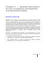
Chapter 11 | Specific instructions for use in explosive
atmospheres and operational safety ........................................ 61
General comments ................................................................................... 61
Cable Entries ............................................................................................ 62
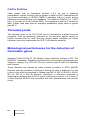
Threaded joints......................................................................................... 62
Metrological performance for the detection of flammable gases ............. 62
Transfer curve .......................................................................................... 63
Scope of use ............................................................................................ 63
Functional safety ...................................................................................... 64
Reliability data .......................................................................................... 64
Special conditions of use ......................................................................... 65
Appendix | Ordering information ......................................... 67
Gas List .................................................................................................... 67
4
OLC(T) 100
User manual
Thank you for choosing this OLDHAM instrument.
All of the necessary actions have been taken in order to ensure your complete
satisfaction with this equipment.
It is important that you read this entire manual carefully and thoroughly.
The extent of our responsibility
OLDHAM shall not be held responsible for any damage to the equipment or for
any physical injury or death resulting in whole or in part from the inappropriate
use, installation, or storage of the equipment, which is the result of not
complying with the instructions and warnings, and/or with the standards and
regulations in force.
OLDHAM does not support or authorise any business, person, or legal entity in
assuming responsibility on behalf of OLDHAM, even though they may be
involved in the sale of OLDHAM products.
OLDHAM shall not be responsible for any damage, direct or indirect, or for
damages and interest, direct or indirect, resulting from the sale and use of any
of its products UNLESS SUCH PRODUCTS HAVE BEEN DEFINED AND
CHOSEN BY OLDHAM FOR THE USE THAT THEY ARE INTENDED.
Ownership clauses
The drawings, specifications, and information herein contain confidential
information that is the property of OLDHAM.
This information shall not, either in whole or in part, by physical, electronic, or
any other means whatsoever, be reproduced, copied, divulged, translated, or
used as the basis for the manufacture or sale of OLDHAM equipment, or for
any other reason without the prior consent of OLDHAM.
5
Warning
This is not a contractual document. In the best interest of its customers and
with the aim of improving performance, OLDHAM reserves the right to alter
the technical features of its equipment without prior notice.
READ THESE INSTRUCTIONS CAREFULLY BEFORE THE FIRST USAGE:
these instructions should be read by all persons who have or will have
responsibility for the use, maintenance, or repair of the instrument.
This instrument shall only be deemed to be in conformance with the published
performance if used, maintained, and repaired in accordance with the
instructions of OLDHAM by OLDHAM personnel or by personnel authorised by
OLDHAM.
Guarantee
Under normal conditions of use and on return to the factory, parts and
workmanship are guaranteed for 3 years, excluding such consumables as
sensors, filters, etc.
Destruction of the equipment
European Union (and EEA) only. This symbol indicates that, in
conformity with directive DEEE (2002/96/CE) and according to local
regulations, this product may not be discarded together with household
waste.
It must be disposed of in a collection area that is set aside for this purpose, for
example at a site that is officially designated for the recycling of electrical and
electronic equipment (EEE) or a point of exchange for authorized products in the
event of the acquisition of a new product of the same type as before.
6
OLC(T) 100
User manual
Chapter 1 | Presentation
Purpose
This range of sensors is designed to detect a particular gas depending on the type
of sensor used.
Operating principle
The measurement sensor converts the target gas into voltage or current. This
electrical parameter is:
either conducted directly via a connecting cable to a dedicated central
measurement unit (as with the OLC 100 explosimeter) that operates on the
principle of the Wheatstone bridge. Such a measurement unit is available in
the OLDHAM range.
or amplified, corrected for temperature, linearised, and converted to a 4-20 mA
signal (as for the OLCT 100) and conducted via a connecting cable to a
centralized unit (measurement unit or industrial automation system).
1 - Presentation
7
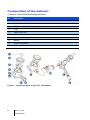
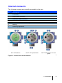
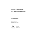
Composition of the detector
A detector comprises the following elements:
Id.
Description
1.
Company label
2.
Cover
3.
PCB protector (for OLCT version).
4.
PCB.
5.
Cable gland inlet.
6.
Enclosure.
7.
Sensor block.
8.
Nozzle.
9.
Ground connection.
10.
LEL sensor (high temperature).
Figure 1 : component parts of an OLCT 100 detector
8
OLC(T) 100
User manual
050
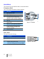
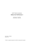
Internal elements
The following elements are internally accessible to the user:
Id.
Description
1.
Terminal for the cable being connected to the controller (measurement unit,
automation).
2.
Sensor block connector.
3.
Calibration ribbon connector.
4.
4 mA adjustment.
5.
Push button access for 4 mA adjustment.
6.
Zeroing.
7.
Sensitivity adjustment.
OLC 100 detector
OLCT 100 explosimeter
OLCT 100 detector for toxic
gases
006
Figure 2 : internal view of the detectors
1 - Presentation
9
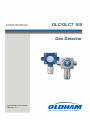
Identifiers
The enclosure has two identifier labels, as described below:
Company label
This in turn groups the detector features together:
Id.
Description
1.
Manufacturer's name.
2.
Type of product
3.
ATEX- IECEx Marking
4.
CE symbol and the number of the
organisation that provided the OLDHAM
production quality certification (INERIS )
5.
Warning..
6.
Type of gas detected and range of
measurement.
7.
Maximum ATEX certification temperature
(excluding metrological performance)
8.
Symbol of Marine Certification and
number of the Approval Agency that
issued the certificate
9.
Recycling symbol.
.
CH4
0-100% LIE
9
008
Figure 3 : Firmplate
Side label
This label shows the following :
Id.
Description
1.
Thread diameter and pitch for cable inlet
1
2.
Detector reference number, less sensor (P/N)
2
3
3.
Detector serial number (S/N)
The first two digits (in this case 09) correspond
to the year of manufacture (in this case 2009)
10
OLC(T) 100
User manual
Figure 4 : side label
010
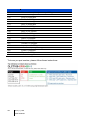
Chapter 2 | Ranges
OLC 100 and OLCT 100 ranges
The OLC 100 range is reserved for the detection of explosive vapor by using a
Wheatstone bridge sensor.
The OLCT 100 range of detectors is provided with an amplifier producing a 2 or 3
wire 4-20 mA analog output. These are transmitter detectors and, therefore, the
letter "T".
OLC 100
OLCT 100 XP
OLCT 100
XPIR
OLCT 100 IS
OLCT 100 HT
Features
Explosion
proof
Explosionproof
Explosionproof
Intrinsically
safe (1)
Explosionproof
(2)
Detection
of
explosive
gases
Catalytic
sensor (VQ1)
Catalytic
sensor (VQ1
or AP 4F) or
semiconductor
Infrared
sensor
Catalytic
sensor
high
temperature
Detection
of toxic
gases
EC
Or SC
EC
Detection
of oxygen
EC
EC
Detection
of CO2
4-20 mA
output
Infrared
sensor
(3)
2 wires for EC
3 wires for SC
3 wires for LEL
3 wires
2 wires
3 wires
(1) Requires the use of a Zener barrier
(2) Sensor can be remote up to 5, 10, or 15 meters using a high temperature cable
(3) mV bridge output, 3 wires
EC : Electrochemical sensor
SC : Semi-conductor sensor.
LEL : Catalytic bead
AP : Poison resistant
Table 1 : comparison of OLC 100 and OLCT 100 series detectors
2 – Ranges
11
12
OLC(T) 100
User manual
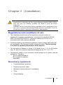
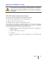
Chapter 3 | Installation
It is recommended that the guides relating to the installation, use, and
maintenance of flammable gas and oxygen detectors (standard EN/IEC 6007929-2) and toxic gas detectors (standard EN 45544-4) should be clearly
understood.
Installation shall be in accordance with the standards in force, classification of the
zone, and in conformity with standards EN/IEC 60079-14 and EN/IEC 61241-14,
the editions in force, or with other national and/or local standards.
Regulations and conditions of use
The installation should meet all the regulations currently in force for
installations in explosive atmospheres, in particular the standards IEC/EN
60079-14 and IEC/EN 60079-17 (whichever editions are in force) or in
accordance with other national standards.
Generally speaking, the ambient temperature, supply voltage, and power that
are mentioned in this document relate to explosion safety. This has nothing
to do with the operating temperatures of the detector.
The equipment is allowed in zones 0 (IS version only), 1, 2, 20 (IS version
only), 21 and 22 for ambient temperatures ranging from -50 ° C to + 70 °.
The detector sensor in the transmitter should always be in contact with the
ambient air. Therefore:
- Do not cover the detector.
- Do not paint the detector.
- Avoid dust.
Necessary equipment
Complete detector assembly
Requisite connector cable
Multimeter (intrinsically safe, if necessary)
Tools
Fixing hardware
3 - Installation
13
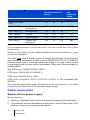
Electrical power supply
Type of detector
Supply (V DC)
OLCT 100 XP HT
OLCT 100 XP LEL
15,5 to 32
15,5 to 32
OLCT 100 XP IR
OLCT 100 XP EC
OLCT 100 XP SC
OLC 100
Maximum
current (mA)
Power consumed
(mW)
110
100
1705
1550
15,5 to 32
80
930
10 to 32
23,5
235
15,5 to 32
100
1550
By Oldham
controller
340
(1)
(1) Depends on the central measurement unit.
Location of the detector
Depending on the density of the gas to be detected or the application, the detector
shall be positioned at the ground level, or on the ceiling at the same height as the
airflow, or near to the air extraction ducts. Heavy gases may be detected at the
ground level, while light gases will be found at ceiling height. Gas densities are
provided on page 28.
Detector positioning
The detector shall be installed with the detector sensor pointing downwards.
For explosive gas detectors only, any tilt of more than 45° from the vertical will
lead to an inaccurate measurement.
014
Figure 5 : sensor pointing downwards (left) and maximum tilt angle for an
explosimeter (right)
14
OLC(T) 100
User manual
Installation of the enclosure shall be secured with 4 x M6 screws and the
appropriate plugs for the supporting material
016
Figure 6 : fixing template for the enclosure
A special holder is available for mounting the detector on the ceiling (see section
on accessories.
In the OLCT 100 HT version, only the OLC20 HT removable detector head can be
used at temperatures from -20°C to + 200°C. The OLCT 100 HT enclosure can
only be used in ambient temperatures from -40°C to + 70°C. The high
temperature cable between the OLCT 100 HT enclosure and the OLC20 HT head
is integral with the instrument and is not user-replaceable.
The cable should be protected mechanically
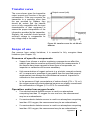
Connector cable
The detector shall be connected to the controller (measurement and automation
unit) by a shielded instrumentation cable, armoured when necessary. The choice
of cable will be dictated by the particular requirements of the installation, distance,
and type of detector (see table below).
Detector
Central unit
Connector
cable
018
Figure 7: the cable connecting the detector to the controller should be chosen with
care
3 - Installation
15
018
Type of detector
Type of sensor
Maximum length (km) for
cable of cross-section as
indicated
0,5mm²
0,9mm²
1,5mm²
24
24
24
0,8
1,4
2,4
Upstream line voltage
(Vcc)
OLCT 100 XP
Catalytic or
semiconductor
OLCT 100 XP (1)
Electrochemical
<4
<4
<4
OLCT 100 XPIR
Infra-red
1,4
2,6
4,4
OLCT 100 IS (2)
Electrochemical
1,8
3,3
<4
OLCT 100 HT
Catalytic, high
temperature
0,8
1,4
2,4
Maximum
load
resistance for
4-20 Ma
250
250
250
(1) for resistance calculations, the assumed load is 120 for 4-20 Ma.
(2) for resistance calculations, the assumed load is 120 for 4-20 Ma, and a 300 Zener
blocking diode.
Warning: all wiring should meet the installation standards and should be described in a system
document for SI installations
The cable must have a braided screen to reduce the influence of electrical and
radio-frequency interference. A cable such as AFNOR M 87-202 01-IT-09-EG-FA
(Nexans) may be used. It shall be selected according to the type of detector and
in accordance with the table shown hereinabove. Below are further examples of
suitable cables:
Non ATEX zone: CNOMO FRN05 VC4V5-F
ATEX zone: GEUELYON (U 1000RHC1)
ATEX zone: GVCSTV RH (U 1000)
ATEX zone: xx-xx-09/15- EG-SF or EG-FA or EG-PF (U 300 compatible with
M87202)
The maximum permissible length will depend on the cross-section of the cable
conductors (see table) and on the minimum supply voltage.
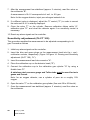
Cable connection
Switch off line power supply
On the controller:
1. Inhibit any installation alarms to avoid unexpected triggering during operation.
2.
16
In accordance with the manufacturer’s instructions, switch off the power to the
module in order to be connected to the detector.
OLC(T) 100
User manual
Cable preparation
The cable shall be taken from the controller (measurement and automation) to the
point of measurement (see Figure 8). The passage, support, and protection of the
cable shall be according to best practice.
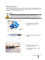
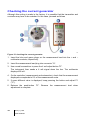
Cable entry
It is essential that the instructions provided by the manufacturer of the
compression gland are followed and the braided screen is correctly connected.
M20x1.5 flamme proof certified cable gland shall be used (see Chapter 11).
1 - Remove the joint and the two
metal washers found in the
sensor.
2 - Arrange the cable as shown in the
picture.
3 - Spread the braided shield as
shown in the picture.
Avoid creating "pigtails" with the
braided shield.
3 - Installation
17
4 - Insert the part back into the
OLCT100.
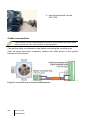
Cable connection
The connection of the cable between the detector and controller should be made
with the power off. The site should be at equal potential
Connect the cable to the detector side before connecting the controller side.
After the wiring has been completed, connect the cable screen to the ground
terminal of the controller.
022
Figure 8: connections for a 2-wire 4-20 Ma detector
18
OLC(T) 100
User manual
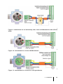
024
Figure 9: connections for an intrinsically safe, 2-wire 4-20 Ma detector with a Zener
diode
023
Figure 10: connections for a 3-wire 4-20 Ma detector
026
Figure 11: connections for a 3-wire OLC 100 type detector
3 - Installation
19
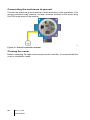
Connecting the enclosure to ground
Connect the enclosure ground terminal to earth according to the regulations. This
ground connection may, however, be taken from the terminal on the screw fixing
the PCB to the inside of the housing.
Figure 12 : Ground connection terminal
028
Closing the cover
Before connecting the cable to the terminal on the controller, it is essential that the
cover is completely closed.
20
OLC(T) 100
User manual
Chapter 4 | Calibration
The tasks described in this chapter are reserved for authorised
trained personnel only, since these tasks are liable to affect
detection reliability
This procedure describes:
zero adjustment;
Sensitivity adjustment.
Necessary equipment
Multimeter (ranges 0-30 mA and 0-2 V), intrinsically safe if necessary.
Cylinder of pure air.
Cylinder of calibration gas, of suitable concentration for the measurement
range (between 30 and 70% of the measurement range).
Commissioning
Prior checks
Check the following points:
Detector housing grounded.
Connexion of the shielding of the cable and the ground to the controller
Integrity of the mechanical mounting (fixings, cable gland, and cover) ensured.
Powering up detector
1. Inhibit any installation alarms to avoid unexpected triggering during the
operation.
2. Connect power to the detector line in accordance with the manufacturer's
instructions.
4 – Calibration
21
Stabilization time
After mounting, it is essential to allow the detector temperature to stabilize. In
addition, after turning the power on, certain sensors require a further pre-heating
time. Any adjustment before the time indicated will result in an incorrect
measurement, which may in turn compromise the safety of the goods and
personnel. The total waiting time is summarised below:
Explosimeter: 2 hours.
Oxygen detector: 1 hour.
Electrochemical detector: 1 hour, excluding:
- NO (nitrogen monoxide): 12 hours.
- HCl (hydrogen chloride): 24 hours.
- ETO (ethylene oxide): 36 hours.
- CH2O (formaldehyde): 36 hours.
Semiconductor sensor: 4 hours.
Infra-red detector: 2 hour.
22
OLC(T) 100
User manual
Calibrating the OLC 100
The cover of the detector remains closed, with any adjustments being
carried out at the central measuring unit.
For an explosimeter, it is recommended that the detector should be
calibrated by using the gas to be detected. If the user would like to
calibrate the detector with a gas other than that detected and
programmed in the factory, reference should be made to the table on
page 30 by using the recommended gas and corresponding coefficient.
Zeroing
Proceed as follows :
034
Figure 13 : Zeroing (OLC 100)
1. Inhibit any alarm signals on the controller.
2. Place the calibration cup onto the detector head (Figure 13, "A").
3. Connect the calibrator cup to the pure air cylinder "D" using a flexible hose "B".
4. Open the valve on the zero air cylinder (flow rate 30 to 60 litres/h) "C".
5. After the measurement has stabilised (approx. 2 minutes), read the display of
the central measuring unit.
A displayed figure of "0.0" corresponds to 0% gas.
6. If a different value is displayed, adjust the "0" on the measuring unit to correct
the value until a reading of exactly 0.0% is obtained.
7. Close the valve "C" on the cylinder. Remove the calibration cup "A" if no
sensitivity control is necessary.
8. Reset any alarm signals on the controller.
4 – Calibration
23
Adjustment of gas sensitivity
This procedure takes place after the zeroing stage:
1. Inhibit any alarm signals on the controller.
2. Place the calibration cup on the detector head (Figure 13, "A").
3. Connect the calibration cup to the calibration gas cylinder "D" by using a
flexible hose "B".
4. Open the valve on the calibration gas cylinder "C" (flow rate 30 to 60 litres/hr).
5. After the measurement has stabilized (approx. 2 minutes), read the display of
the central measuring unit.
6. Adjust "S" on the measuring unit in order to display the desired value.
7. Close valve "C" on the cylinder and remove the calibration cup "A".
8 . Walt for the measured signal to return to zero and reset the alarm signals on
the controller.
24
OLC(T) 100
User manual
Calibrating the OLCT 100
Wait for the stabilization time on power-up.
For a LEL detector, it is recommended to calibrate with the targeted
gas. Should the operator calibrate with another gas, please refer to
tables on pages 32 to 34 to know the recommended calibration gas and
the cross sensitivity factor.
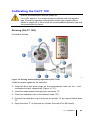
Zeroing (OLCT 100)
Proceed as follows:
038
Figure 14: Zeroing and Sensitivity adjustment (OLCT 100)
Inhibit any alarm signals on the controller.
2. Insert the blue and green plugs on the measurement lead into the + and multimeter sockets, respectively (Figure 14, "H")
3. Insert the measurement lead plug into connector "A".
4. Place the calibration cup on the detector head ("D").
5. Connect the calibration cup to the pure air cylinder "G" by using a flexible hose
"E".
6. Open the valve "F" on the pure air cylinder (flow rate 30 to 60 litres/h).
4 – Calibration
25
7. After the measurement has stabilized (approx. 2 minutes), read the value on
the multimeter "B".
A measurement of 0.4 V corresponds to 4 mA, i.e. 0% gas.
Note: for the oxygen detector, inject pure nitrogen instead of air.
8. If a different value is displayed, adjust the "0" control ("C") in order to correct
the value until 0.4 V is exactly displayed.
9. Close the valve "F" on the cylinder. Remove calibration ribbon cable "A",
calibration pipe "D", and close the detector again if no sensitivity control is
necessary.
10. Reset any alarm signals on the controller.
Sensitivity adjustment (OLCT 100)
This procedure enables the measurement to be adjusted corresponding to x%
gas. Proceed as follows
1. Inhibit any alarm signals on the controller.
2. Insert the blue and green plugs on the measurement lead into the + and multimeter sockets, respectively (Figure 14Figure 14: Zeroing and Sensitivity
adjustment (OLCT 100), "H").
3. Insert the measurement lead into connector "A".
4. Place the calibration cup on the detector head ("D").
5. Connect the calibration cup to the calibration gas cylinder "G" by using a
flexible hose "E".
A stainless steel pressure gauge and Teflon tube must be used for toxic
gases and Freons.
Note: for an oxygen detector, use a cylinder of pure air or roughly 19%
oxygen.
6. Open the valve "F" on the calibration gas cylinder (flow rate 30 to 60 litres/h).
7. Once the measurement has stabilized (approx. 2 minutes), read the value on
the multimeter.
26
OLC(T) 100
User manual
Use the following formula to determine the voltage value that is to be displayed:
Voltage displayed (mV) = 400 + (1600 x calibration gas concentration)
Sensor range
For example, for a range of 1000 ppm CO with a calibration gas cylinder of
300 ppm, the voltage displayed will be:
Voltage displayed (mV) = 400 + (1600 x 300) = 880 mV
1000
8. If a different value is displayed, adjust the "S" control ("C") to correct the value
until an exact value of the calibration gas is displayed.
9. Close the valve "F" on the cylinder. Remove measurement cable "A", calibrate
cup "D", and close the detector again.
10. Wait for the measured signal to return to zero and reset the alarm signals on
the controller.
4 – Calibration
27
Calibration coefficients of explosive gases for catalytic detectors
When a VQ1 type sensor is used (available for OLC 100 and OLCT 100), the
coefficients are as follows:
Gas
Chemical
Formula
LEL
(%)
LSE
(%)
Flash
point (°C)
C4H8O2
2,10%
11,50%
-4°C
Acetone
C3H6O
2,15
13,00
Acetylene
C2H2
1,50
100
Acrylic acid
C3H4O2
5,30%
Butyl acrylate
C7H12O2
Ethyl acrylate
-
Vapor Coefficient
density Calibration gas
-
Coefficient
Coefficient Coefficient
- Calibration gas
- Calibration gas
CH4(methane)
H2(Hydrogen)
C4H10 (Butane)
C5H12 (Pentane)
3,0
1,65
1,35
0,90
0,80
-18
2,1
1,65
1,35
0,90
0,80
-18
0,9
2,35
1,90
1,25
1,15
26,00%
54°C
2,5
2,50
2,00
1,35
1,20
1,20%
8,00%
37°C
4,4
3,50
2,80
1,85
1,70
C5H8O2
1,70%
13,00%
-2°C
3,5
3,05
2,45
1,65
1,50
C3H3N
2,80%
28,00%
-1°C
1,8
1,45
1,20
0,80
0,70
Ammoniac
NH3
15,00
30,20
< -100
0,6
0,90
0,75
0,50
0,45
Benzene
C6H6
1,20%
8,00%
-11°C
2,7
4,00
3,20
2,15
1,90
1.3Butadiene
C4H6
1,40%
16,30%
-85°C
1,9
2,55
2,05
1,35
1,25
Butane
Ethyl acetate
Acrylonitrile
Calibration gas
C4H10
1,50
8,50
-60
2,0
1,90
1,55
1,00
0,90
Butanol
(Butyl Alcool)
C4H10O
1,4%
11,3%
29°C
2,6
1,95
1,60
1,05
0,95
2 - Butanone
(MEK)
C4H8O
1,80%
11,50%
-4°C
2,5
3,90
3,15
2,10
1,90
Cyclohexane
C6H12
1,20%
8,30%
-17°C
2,9
2,00
1,60
1,10
1,00
Dimethylether
C2H6O
3,00%
27,00%
-41°C
1,6
1,80
1,45
0,95
0,90
Dodecane
C12H26
0,60%
~6,0%
74°C
5,9
4,00
3,20
2,15
1,90
Ethane
C2H6
3,00
15,50
135
1,0
1,50
1,20
0,80
0,75
Ethanol
C2H6O
3,30
19,00
13
1,6
2,15
1,75
1,30
1,00
(C2H5)2O
1,70%
36,00%
-45°C
2,6
1,90
1,55
1,00
0,90
C2H4
2,70
34,00
- 135
1,0
1,65
1,35
0,90
0,80
LPG
Prop+But
1,65
~9,0
< -50
1,9
1,90
1,55
1,00
0,90
Diesel
Melange
0,60
~6,0
55
>4
3,20
2,60
1,70
1,55
CH4
5,00
15,00
-188
0,6
1,05
Heptane
C7H16
1,10
6,70
-4
3,5
2,20
1,80
1,20
1,05
Hexane
2,10
1,70
1,15
1,00
Ether
(Diethylether)
Ethylene
Natural Gas
C6H14
1,20
7,40
-23
3,0
Hydrogen
H2
4,00
75,60
-
0,069
Isobutane
C4H10
1,50%
8,40%
-83°C
2,0
1,50
1,20
0,80
0,75
C4H8
1,60%
10,00%
<-10°C
1,9
2,20
1,80
1,20
1,05
C3H8O
2,15%
13,50%
11,7°C
2,1
1,60
1,30
0,85
0,80
Isobutene
Isopropanol
28
OLC(T) 100
User manual
1,00
Gas
Chemical
Formula
LEL
(%)
LSE
(%)
Flash
point (°C)
C10 - C16
0,70%
5,00%
> 50 °C
C5H8O2
2,10%
12,50%
CH4
5,00
Methanol
CH3OH
Naphta
melange
(Mixture)
Nonane
-
Vapor Coefficient
density Calibration gas
-
Coefficient
Coefficient Coefficient
- Calibration gas
- Calibration gas
CH4(methane)
H2(Hydrogen)
C4H10 (Butane)
C5H12 (Pentane)
>4
5,00
4,00
2,65
2,40
2°C
3,5
2,25
1,80
1,20
1,10
15,00
-188
0,55
1,00
5,50%
44,00%
11°C
1,1
1,40
1,15
0,75
0,70
0,90%
5,90%
> 44°C
>4
3,50
2,80
1,85
1,70
C9H20
0,70
5,60
31
4,4
4,40
3,55
2,35
2,10
Octane
C8H18
1,00
6,00
12
3,9
2,70
2,20
1,45
1,30
Ethylene
Oxyde
C2H4O
2,60%
100%
-20°C
1,5
2,10
1,70
1,15
1,00
Propylene
oxide
C3H6O
1,90%
37,00%
70°C
2,0
2,35
1,90
1,25
1,15
Pentane
C5H12
1,40
8,00
-49
2,5
Propane
C3H8
2,00
9,5
-104
1,6
1,55
1,25
0,85
0,75
Propylene
C3H6
2,00
11,70
-107,8
1,5
1,65
1,35
0,90
0,80
Styrene
C8H8
1,1
8,00
31
3,6
6,30
5,05
3,35
3,00
/
1,10%
~6,0 %
21°C
3à4
1,80
1,45
0,95
0,90
C7H8
1,20
7
5
3,1
4,00
3,20
2,15
1,90
-
0,8%
6,0%
35°C
4,7
3,50
2,80
1,85
1,70
Triethyl
amine
C6H15N
1,20%
8%
-15°C
3,5
2,05
1,65
1,10
1,00
White Spirit
melange
(Mixture)
1,10%
6,50%
>30°C
>4
3,50
2,80
1,85
1,70
C8H10
1,00
7,60
25
3,7
4,00
3,20
2,15
1,90
Kerosene
(JP4)
Methyl
Methacrylate
Methane
Gasoline lead
free
Toluene
Turpentine
Oil
Xylene
Calibration gas
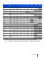
1,00
Cells with a grey background: gases recommended for calibrating the detector
Table 2 : Calibration coefficients of explosive gases for catalytic detectors (VQ1)
4 – Calibration
29
When an anti-poison 4F type sensor is used (only available for OLCT 100), the
coefficients are as follows:
Gas
Chemical
Formula
LEL %
LSE
%
Vapor
density
CH4
Coef
C5H12
Coef
H2
Coef
1,1
Acetone
C3H6O
2,15
13,0
2,1
1,8
0,9
Acetylene
C2H2
1,5
100
0,9
1,4
0,7
Ammoniac
NH3
15,0
30,2
0,6
1,0
0,5
Benzene
C6H6
1,2
8,0
2,7
2,10
1,05
n-Butane
C4H10
1,5
8,5
2,0
1,8
0,9
Ethane
C2H6
3,0
15,5
1,0
1,4
0,7
Ethanol
C2H6O
3,3
19,0
1,6
1,6
0,8
Ethylene
C2H4
2,7
34,0
1,0
1,4
0,7
n-Hexane
C6H14
1,2
7,4
3,0
2,85
1,4
Hydrogen
H2
4,0
75,6
0,07
Isopropanol
C3H8O
2,15
13,5
2,1
1,8
0,9
1,0
JP-4
3,0
1,5
JP-5
3,1
1,55
3,2
1,6
JP-8
Methane
CH4
5,0
15,0
0,55
1,0
Methanol
CH3OH
5,5
44,0
1,1
1,35
0,65
n-Pentane
C5H12
1,4
8,0
2,5
2,0
1,0
Propane
C3H8
2,0
9,5
1,6
1,6
0,8
Styrene
C8H8
1,1
8,0
3,6
2,4
1,2
Toluene
C7H8
1,2
7,0
3,1
2,5
1,25
Xylene
C8H10
1,0
7,6
3,7
2,4
1,2
Cells with a grey background: gases recommended for calibrating the detector
Table 3 : Calibration coefficients of explosive gases for catalytic detectors
with a 4F sensor.
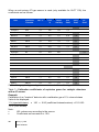
Example
Calibration of an "acetone" detector with a calibration gas of 1% volume butane
Value to be displayed:
1 %( injected butane)
1,5 % (LEL butane)
x 100 x 0.95 (coefficient butane/acetone) = 63 % LEL
Note:
LEL values vary according to the source.
Coefficients are accurate to ± 15%.
30
OLC(T) 100
User manual
Chapter 5 | Preventive
maintenance
Periodic checks enable the equipment and installation to remain in conformity
and ensure reliable detection. This chapter describes what preventative action
should be taken and at what intervals. Inspection and maintenance are carried
out in accordance with standards in force EN60079-17 or IEC 60079-17, with
whatever editions are in force or with other national standards.
Frequency of maintenance
Gas detectors are safety devices. OLDHAM recommends the regular testing of
fixed gas detection installations. This type of test consists of injecting the
calibration gas into the detector at a sufficient concentration to activate the pre-set
alarms. It is to be understood that this test is in no way a replacement for a
detector calibration.
The frequency of gas tests depends on the industrial application where the
detector is in use. Frequent inspections should be made in the months following
the commissioning of the installation, and should then become more widely
spaced provided that no significant deviation is observed. If a detector should fail
to react in contact with the gas, calibration is essential. The frequency of
calibrations shall be appropriate according to the results of the tests (humidity,
temperature, dust, etc.); however, it must not exceed one year.
The general manager should put safety procedures in place on-site. OLDHAM
cannot be held responsible for their enforcement.
To attain SIL capability level 1 in accordance with European standard EN
50402, Requirements relating to the safety operation of fixed gas
detection systems, the maintenance interval for explosive gas detectors
must be no more than 6 months. To obtain SIL capability level 2, the
maintenance interval must be no more than 3 months
5 – Preventive maintenance
31
Actions
Periodic maintenance comprises the following actions:
Removal of dust from the sensor’s protective housing, using only a dry
cloth. No water or solvents should be used. Severely dusty heads or
sensors should be replaced immediately.
For use in dusty explosive atmospheres, the user should undertake full
and regular cleaning to avoid the build-up of dust. The maximum
permissible thickness of a dust layer must be less than 5 mm.
Replacement of screws: if the screws on the fire-proof part “d” of the
body need to be replaced, screws of equal quality or better than A4.70
should be used.
Zero inspection with pure air.
Gas sensitivity inspection and possible adjustment, as per Chapter 4
|
Calibration.
32
OLC(T) 100
User manual
Chapter 6 | Maintenance
Maintenance primarily comprises changing any sensors that no longer meet
their initial metrological characteristics.
Since they are liable to affect detection reliability, the tasks
described in this chapter are reserved for authorized trained
personnel only.
Inspection and maintenance shall be carried out in accordance
with standards EN60079-17 or IEC 60079-17, with whatever
editions are in force or with other national standards.
The 4 mA level is factory-set. This value cannot be changed or
adjusted. This check does not concern explosimeter OLC 100.
Opening the cover
This stage is necessary for the 4 mA check, zeroing, and calibration of the
detector. Unscrew the lid of the enclosure by using a tool positioned like a cross.
. All the necessary steps should be taken before opening the lid of
the enclosure if it is installed in an ATEX zone, in particular:
A fire permit from the appropriate department.
Continuous use of a portable explosimeter.
Use of an intrinsically safe multimeter.
Reduction to an absolute minimum of the time involved.
This observation does not concern intrinsically safe versions that
are used in an ATEX gas zone (see Chapter 11 | Specific
instructions for use in explosive atmospheres and operational
safety).
6 - Maintenance
33
Checking the current generator
Although this setting is made in the factory, it is possible that the transmitter and
controller may have to be matched. In this case, proceed as follows
030
Figure 15: checking the current generator
1. Insert the blue and green plugs on the measurement lead into the + and –
multimeter sockets, respectively.
2. Insert the measurement lead plug into connector "A".
3. Use a small screwdriver to press the 4 mA adjust button "D".
The instrument then sends a 4 mA signal down the line. The multimeter
displays 400 mV.
4. On the controller (measurement and automation), check that the measurement
displayed corresponds to 0% of the measurement scale.
5. If some different value is displayed, keep pressing the button and adjust P1
("C").
6. Release the push-button "D". Remove the measurement lead when
adjustment is complete.
34
OLC(T) 100
User manual
Possible errors
The table below summarizes the various possible detector errors:
OLC 100 explosimeter
Observed fault
Possible cause
Action
Zero setting not
possible
Sensor
Replace the sensor
Cable
Check cable
Main unit detector module
Check module
Sensitivity
adjustment not
possible
Sensor
Connector cable
Inappropriate calibration gas
Replace the sensor
Check cable
Check calibration gas
concentration
High gas
concentration
indication
Maladjustment
Zero and span the detector
6 - Maintenance
35
OLCT 100 Detector
Observed fault
Possible cause
Action
Line current 0 mA
Connector cable
Power supply
PCB
Check cable
Check voltage
Replace the PCB
Line current < 1mA
Sensor
PCB
Line resistance too high
Power supply
Power the detector down then
power it up (Off/On)
Replace the sensor
Replace the PCB
Check cable
Check voltage
Analog output is
frozen at 20 mA
Gas concentration has
reached 100% LEL
Proceed a power cycle (Off/On)
Zero and span the detector
Courant de ligne
>23mA
Over Range
Adjust zero and sensitivity
settings
Replace the sensor
Zero setting not
possible
Sensor
PCB
Replace the sensor
Replace the PCB
Sensitivity
adjustment not
possible
Sensor
PCB
Replace the sensor
Replace the PCB
High gas
concentration
indication
Maladjustment
Adjust zero and sensitivity
settings
030
36
OLC(T) 100
User manual
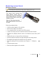
Replacing sensor block
Standard Version
First follow the instructions in the section Opening the cover
The sensor block encloses the
actual detector sensor itself. A
sensor block can only be associated
with a defined detector. A guide pin
ensures that the sensor block goes
together correctly
106
Figure 16: The sensor block (the
black component) fits in the cover of
the head
Follow the procedure below :
Inhibit any alarm signals on the controller.
Switch off the supply to the detector.
For a catalytic sensor, first remove the PCB connector.
Loosen the locking screw on the detector head and unscrew the head.
Withdraw the (catalytic) detector head or the defective sensor block (OLCT
100).
Replace the worn-out sensor with an identical part.
Screw the detector head back on again and tighten the locking screws.
Re-establish the supply to the detector from the controller.
Adjust the settings for the new detector (see Chapter 4 | Calibration,
25).
Close the detector cover.
Reset any alarm signals on the controller.
6 - Maintenance
page
37
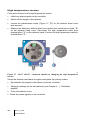
High temperature version
Proceed as follows for the high temperature version.
Inhibit any alarm signals on the controller.
Switch off the supply to the detector.
Loosen the maintenance screw (Figure 17, "B") on the detector head cover
and remove it.
Replace the defective detector head and replace the maintenance screw "B"
on the detector head cover. Disconnect the high temperature cable from
terminal block "A" on the detector head. Connect the high temperature cable to
terminal block "A".
048
Figure 17 : OLCT 100 HT – elements specific to changing the high temperature
sensor
Screw the detector head back on again and tighten the locking screws.
Re-establish the supply to the detector from the controller.
Adjust the settings for the new detector (see Chapter 4 | Calibration,
page25).
Close the detector cover.
Reset any alarm signals on the controller .
.
38
OLC(T) 100
User manual
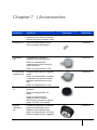
Chapter 7 | Accessories
Accessory
Utilization
Tools kit
Tool kit for OLCT 100 including
calibration cup, Allen key, sensor
removal key and connector cable
6147879
humidifier kit
Used for the calibration of the
semi-conductor transmitters
6335918
Calibration
cup
Facilitates the injection of
calibration gas on the sensor
Effect on measurement:
measurement similar to that for
natural diffusion
Effect on response time: none
6331141
PTFE remote
sampling cup
Enables measurement in bypass
mode
Effect on measurement: no effect
if calibration is carried out under
the same conditions (cup, flow
rate)
Effect on response time: none
Splash-guard
kit
Remote
calibration
cup
Protects the detector against
splashes
Effect on measurement: no
effect.
Effect on response time:
response time for natural
diffusion can increase for certain
gases. Contact us for details.
Illustration
Reference
204
6327910
200
6329004
202
6327911
Enables the detection of ambient
gases simultaneously with a
calibration gas injection pipe.
Effect on measurement: no effect.
Effect on response time: negligible.
214
7 - Accessories
39
Accessory
Utilization
PTFE water
barrier
Protects the gas inlet from dust
and splashing
Effect on measurement: no
effect, but cannot be used for
detecting O3, HCl, HF, or CL2.
Effect on response time:
response time increased (contact
us for heavy gases of a density
greater than 3 and at low
concentrations < 10 ppm
Universal
Pitot tube
Enables the measurement of a
gas passing through a sheath
Requires the use of the gas
circulation head
Effect on measurement: no
effect.
Effect on response time:
negligible.
Mounting kit
Enables a detector to be fixed to
the ceiling.
Effect on measurement: no
effect.
Effect on response time: no effect.
Sunshield
Protects any detector mounted
on the outside of a building.
Effect on measurement: no
effect.
Effect on response time:
negligible.
Illustration
Reference
6335975
216
6793322
224
6322420
218
6123716
222
Wall
mounting gas
collector
Allows the sensor to detect more
quickly the gas. (Wall mounting)
Effect on measurement: no
effect.
Effect on response time: response
time can increase up to 10%.
6331169
Ceiling gas
collector
Allows the sensor to detect more
quickly the gas. (Ceiling)
Effect on measurement: no
effect.
Effect on response time: response
time can increase up to 10%.
6331168
40
OLC(T) 100
User manual
Accessory
Utilization
Replacement
adaptater kit
Enables replacement of an
existing detector without having
to re-drill holes.
Illustration
Reference
6793718
220
B301172
Duct
Mounting kit
7 - Accessories
41
Cable gland
Purpose
Reference
M20 cable gland for non-armoured cable
Material: stainless steel
6343493
M20 cable gland for non-armoured cable
Material: Nickel-plated brass (not recommended
for use with ammonia or acetylene)
6343499
M20 cable gland for armoured cable
Material: stainless steel
6343489
M20 cable gland for armoured cable.
Material: Nickel-plated brass (not recommended
for use with ammonia or acetylene)
6343495
42
OLC(T) 100
User manual
Chapter 8 | Spare parts
List of spares for the various detectors
Part Number
Description
6 314 010
Catalytic sensor 0-100% LEL CFC100 VQ1 for OLC 100
6 313 994
Catalytic sensor 0-100% LEL CFC100 4F for OLCT 100
6 314 042
Infrared sensor 0-100% LEL CH4 for OLCT 100
6 314 102
Infrared sensor 0-100% LEL (4.4% vol) CH4 pour OLCT 100
6 314 108
Infrared sensor 0-100% VOL CH4 pour OLCT 100
6 314 103
Infrared sensor 0-100% LEL C3H8 pour OLCT 100
6 314 104
Infrared sensor 0-100% LEL C4H10 pour OLCT 100
6 314 105
Infrared sensor 0-100% LEL Isobutane pour OLCT 100
6 314 106
Infrared sensor 0-100% LEL GPL pour OLCT 100
6 314 128
Infrared sensor 0-100% LEL C5H12 pour OLCT 100
6 314 107
Infrared sensor 0-100% LEL ethanol pour OLCT 100
6 314 142
Infrared sensor 0-5000 ppm CO2 pour OLCT 100
6 314 043
Infra-red sensor 0-5% vol. CO2 for OLCT 100
6 314 109
Infrared sensor 0-10% vol CO2 pour OLCT 100
6 314 145
Infrared sensor 0-100% vol CO2 pour OLCT 100
6 314 016
Electrochemical sensor 0-30% O2 for OLCT 100
6 314 017
Electrochemical sensor 0-100 ppm, 0-500 ppm and 0-1000 ppm
CO for OLCT 100
6 314 018
Electrochemical sensor 0-30.0 ppm, 0-100 ppm H2S for OLCT
100
6 314 019
Electrochemical sensor 0-1000 ppm H2S for OLCT 100
6 314 125
Electrochemical sensor 0-5000 ppm H2S pour OLCT 100
6 314 020
Electrochemical sensor 0-100 ppm, 0-300 ppm and 0-1000 ppm
NO for OLCT 100
6 314 021
Electrochemical sensor 0-10.0 ppm and 0-30.0 ppm NO2 for
OLCT 100
8 – Spare parts
43
Part Number
Description
6 314 022
Electrochemical sensor 0-10.0 ppm, 0-30.0 ppm and 0-100 ppm
SO2 for OLCT 100
6 314 025
Electrochemical sensor 0-10.0 ppm Cl2 for OLCT 100
6 314 023
Electrochemical sensor 0-2000 ppm H2 for OLCT 100
6 314 026
Electrochemical sensor 0-30.0 ppm, 0-100 ppm HCl for OLCT
100
6 314 028
Electrochemical sensor 0-10.0 ppm and 0-30.3 ppm HCN for
OLCT 100
6 314 029
Electrochemical sensor 0-100 ppm NH3 for OLCT 100
6 314 030
Electrochemical sensor 0-1000 ppm NH3 for OLCT 100
6 314 031
Electrochemical sensor 0-5000 ppm NH3 for OLCT 100
6 314 033
Electrochemical sensor 0-1.00 ppm PH3 for OLCT 100
6 314 035
Electrochemical sensor 0-3.00 ppm ClO2 for OLCT 100
6 314 024
Electrochemical sensor 0-30.0 ppm ETO for OLCT 100
6 314 032
Electrochemical sensor 0-1.00 ppm AsH3 for OLCT 100
6 314 027
Electrochemical sensor 0-50.0 ppm SiH4 for OLCT 100
6 314 034
Electrochemical sensor 0-1.00 ppm COCl2 for OLCT 100
6 314 036
Semiconductor sensor for methyl and methylene chloride for
OLCT 100
6 314 037
Semiconductor sensor for R12, R22, R123 and FX56 freons for
OLCT 100
6 314 038
Semiconductor sensor for R134a, R142b, R11, R23, R141b,
R143a, R404a, R507, R410a, R32, R227, R407c and R408a
freons for OLCT 100
6 314 039
Semiconductor sensor for ethanol, toluene, isopropanol, 2butanone and xylene for OLCT 100
6 451 626
OLC 100 Board
6 451 646
OLCT 100 IR Board
6 451 621
OLCT 100 SC Board
6 451 594
OLCT 100 catalytic Board
6 451 623
OLCT 100 toxic Board
6 451 649
Usual EC OLCT 100 Board
6 451 648
OLCT 100 O2 Board
44
OLC(T) 100
User manual
Chapter 9 | Declarations of EC
conformity
The document hereafter (2 pages) reproduces the EC declaration of conformity.
9 – Declarations of EC conformity
45
46
OLC(T) 100
User manual
9 – Declarations of EC conformity
47
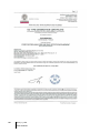
The document below (1 page) reproduces the 96/98/EC Marine Directive
declaration of conformity (followed by the certificate, 3 pages).
48
OLC(T) 100
User manual
9 – Declarations of EC conformity
49
50
OLC(T) 100
User manual
9 – Declarations of EC conformity
51
52
OLC(T) 100
User manual
Chapter 10 | Technical
specifications
Dimensional characteristics
M44 pitch 1
M44 pitch 1
M44 pitch 1
044
Figure 18: dimensional characteristics of the detectors
10 – Technical specifications
53
General Specifications
Supply voltage at the detector
terminals:
OLC 100: 340 mA (current supply)
OLCT 100 XP HT: 15.5 V to 32 V
OLCT 100 XP LEL: 15.5 V to 32 V
OLCT 100 XP IR: 13.5 V to 32 V
OLCT 100 XP EC: 10 V to 32 V
OLCT 100 XP SC: 15.5 V to 32 V
Average consumption:
OLC 100: 340 mA
OLCT 100 XP HT: 100 mA
OLCT 100 XP LEL: 110 mA
OLCT 100 XP IR: 80 mA
OLCT 100 XP EC: 23.5 mA
OLCT 100 XP SC: 100 mA
Output current (signal):
Current source encoded from 0 to 23 mA (non
isolated)
Linear 4 to 20 mA current reserved for measurement
0 mA: electronic fault or no power supply
< 1 mA: fault
2 mA : initialization mode
frozen to 20 mA : the concentration of combustible
gas has reached 100% LEL
Type of cable
Cable inlet:
M20x1.5 (cable gland not suppled) or ¾ NPT
Maximum diameter of cable
entering the detector:
12 mm
Electromagnetic compatibility:
Conforms to EN50270
Ingress Protection:
IP66
Approvals :
Conforms to European Directive ATEX 94/9/CE (see
attached Declaration) and to IEC Ex schedule for fireproof detectors
SIL 2 in accordance with EN50402:05 /EN61508:11
Performance approved according to EN 60079-29-1:07
(VQ1 catalytic bead)
54
OLC(T) 100
User manual
Explosimeter: screened, 3 active wires
HT Explosimeter: screened, 3 active wires
Electrochemical detector: screened, 2 active wires
Infra-red detector: screened, 3 active wires
Semiconductor detector: screened, 3 active wires
Weight :
Materials:
Epoxy painted aluminum, 316 Stainless Steel in option
OLC 100: 0.950 kg.
OLCT 100 XP HT: 1.8 kg.
OLCT 100 XP LEL: 1.0 kg.
OLCT 100 XP IR: 1.1 kg.
OLCT 100 XP EC: 1.1 kg.
OLCT 100 XP SC: 1.1 kg.
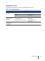
Catalytic sensor (OLCT 100 XP)
Common characteristics
Measurement range
0–100% LEL
Measurement principle:
catalytic
Accuracy:
see table below
Temperature range:
see table below
Relative humidity:
0 to 95% RH (non-condensing relative humidity)
Pressure:
atmospheric ± 10%
Response time:
T50 = 6 seconds. T90 = 15 seconds for Methane
Lifetime (typical)
48 months
Storage conditions:
-50 to 70°C, 20 to 60% RH, 1 bar ± 10%, 6 months
maximum
Warm-up time (max)
2 hours to first switching on power
Specific characteristics
Type of sensors
Accuracy
Operating
temperature
range
Anti-poison sensor
4F (unmarked
sensor)
1% LEL between 0- 70 %LEL
2% of the measurement between 71 and
100% LEL
-40 to +70°C
VQ1 sensor
(sensor with
identifying mark)
1% LEL between 0- 70 %LEL
OLCT 100 : 2% of the measurement between 71
and 100% LEL
OLC 100 : 5% of the measurement between 71
and 100 % LEL
-40 to +70°C
VQ1 sensor, high
temperature
assembly
1% LEL between 0-70%LEL
2% of the measurement between 71 and
100% LEL
-20 to +200°C
10 – Technical specifications
55
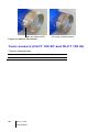
Mark on sensor VQ1
4F poison resistant sensor
Figure 19: mark on VQ1 sensor
Toxic sensors (OLCT 100 XP and OLCT 100 IS)
Common characteristics
Measurement principle:
Electrochemical sensor
Pressure:
Atmospheric ± 10%
56
OLC(T) 100
User manual
Type of gas
Measurement
range
(ppm)
XP
Version
IS
Version
Temperature
range °C
% RH
Accuracy
(ppm)
Lyfe
(months)
Reponse
time
T50 / T90 (s)
Storage
conditions
Warmup time
max (h)
AsH3
Arsine
1,00
-20 à +40
20 - 90
+/- 0,05
18
30/120
(1)
1
CH2O
Formaldéhyde
50,0
-20 à +50
15 - 90
+/- 1,5
36
50/240
(1)
36
Cl2
Chlore
10,0
-20 à +40
10 - 90
+/- 0,4
24
10/60
(1)
1
ClO2
Dioxyde de chlore
3,00
-20 à +40
10 - 90
+/- 0,3
24
20/120
(1)
1
CO
Monoxyde de
carbone
100
300
1000
-20 à +50
11 - 90
+/- 3
(gamme
0-100)
36
15/40
(1)
1
COCl2
Phosgene
1,00
-20 à +40
15 - 90
+/- 0,05
12
60/180
(2)
1
ETO
Oxyde d'ethylene
30,0
-20 à +50
15 - 90
+/- 1
36
50/240
(1)
36
H2
Hydrogene
2000
-20 à +50
15 - 90
+/-5 %
24
30/50
(1)
1
H2S
Hydrogene sulfure
30,0
100
1000
-40 à +50
11 - 90
+/- 1,5
(gamme
0-30)
36
15/30
(1)
1
HCl
Acide chlorhydrique
30,0
100
-20 à +40
15 - 95
+/- 0,4
(gamme
0-10)
24
30/150
(1)
24
10 – Technical specifications
57
NH3
Ammoniac
100
1000
5000
-20 à +40
15 - 90
+/- 5
+/- 20
+/-150 ou
10%
24
50/90
50/90
50/120
(1)
1
NO
Monoxyde d’Azote
100
300
1000
-20 à 50
11 - 90
+/- 2
(gamme
100)
36
10/30
(1)
1
NO2
Dioxyde d’Azote
10,0
30,0
-20 à 50
11 - 90
+/- 0,8
24
30/60
(1)
12
O2
Oxygene
-20 à +50
15 - 90
0,4 % vol
(de 15 à
22 % O2)
30
6/15
(1)
Aucun
(3)
PH3
Phosphine
1,00
-20 à +40
20 - 90
+/- 0,05
18
30/120
(1)
1
SiH4
Silane
50,0
-20 à +40
20 - 95
+/- 1
18
25/120
(1)
1
SO2
Dioxyde de Soufre
10,0
30,0
100
-20 à +50
11 - 90
+/- 0,7
(gamme
0-10)
36
15/45
(1)
1
(1)
58
4 – 20 °C
20 – 60 % RH
1 bar ± 10 %
6 months
maximum
OLC(T) 100
User manual
0-30% vol
(2)
4 – 20 °C
20 – 60 % RH
1 bar ± 10 %
3 months maximum
(3)
If cartridge is
mounted in the
transmitter
Semiconductor sensors (OLCT 100 XP)
Common characteristics
Measurement principle:
semiconductor
Temperature range:
-20°C to +55°C
Relative humidity:
20 to 95% RH (non-condensing relative humidity)
Pressure:
atmospheric ± 10%
Lifetime (typical):
40 months
Storage conditions:
-20 to 50 ℃, 20 to 60% RH, 1 bar ± 10%, 6 months
maximum
Warm-up time (max):
4 hours to first switching on power
Type of gas
Measurement
range
Accuracy
T50 / T90 (s)
500 ppm
500 ppm
+/- 15% (from 20
to 70% FS)
25/50
Freon R12
Freon R22
Freon R123
FX56
1 %vol
2000 ppm
2000 ppm
2000 ppm
+/- 15% (from 20
to 70% FS)
25 / 50
Freon R134 a
Freon R11
Freon R23
Freon R143 a
Freon R404 a
Freon R507
Freon R410 a
Freon R32
Freon R407 c
Freon 408 a
2000 ppm
1 % vol
1 % vol
2000 ppm
2000 ppm
2000 ppm
1000 ppm
1000 ppm
1000 ppm
4000 ppm
+/- 15% (from 20
to 70% FS)
25 / 50
Ethanol
Toluene
Isopropanol
2-butanone ( MEK)
Xylene
500 ppm
500 ppm
500 ppm
500 ppm
500 ppm
+/- 15% (from 20
to 70% FS)
25 / 50
Methyl chloride
Methylene chloride
CH3Cl
CH2Cl2
10 – Technical specifications
59
Infrared sensors (OLCT 100 XP-IR)
Measurement range:
0–100% LEL (explosive gases)
0-100% Vol CH4
0-5000ppm CO2
0–5% CO2 (carbon dioxide)
0-10% CO2
0-100% CO2
Measurement principle:
Infra-red absorption
Accuracy:
- CO2 version: +/- 3% of full-scale at mid-scale (20°C)
- LEL version: +/- 5% of full-scale at mid-scale (20°C)
Temperature range:
-40 to +55 °C (LEL and Vol CH4)
-20 to +50 °C (CO2)
Relative humidity:
0 to 95 % RH (non-condensing relative humidity)
Pressure:
Partial pressure measurement (the measurement
changes with pressure)
Response time:
- CO2 version: T50 11 s and T90 30 s
- LEL version: T50 11 s and T90 30 s
Lifetime (typical):
60 months
Storage conditions:
4–20°C
10–60% RH
1 bar ± 10%
6 months maximum
Warm-up time (max):
2 hours to first switching on power
60
OLC(T) 100
User manual
Chapter 11 | Specific instructions
for use in explosive atmospheres
and operational safety
General comments
OLC/OLCT 100 conforms to the requirements of European Directive ATEX
94/9/CE relating to explosive Dust and Gas atmospheres. On account of their
metrological performance as tested by the accredited organization INERIS (in
process), the OLC/OLCT 100 transmitter detectors intended for the measurement
of explosive gases are classed as safety devices in the sense of the European
Directive and may, therefore, contribute to limiting the risks of explosion.
The information given in the following sections should be respected and taken into
account by the manager of the site where the equipment is installed. As far as the
aim of improving the health and safety of workers who are exposed to the risks of
explosive atmospheres is concerned, refer to European Directive ATEX
1999/92/CE.
OLC/OLCT 100 detectors also conform to the requirements of the IEC
international certification scheme relating to explosive Dust and Gas atmospheres.
Two modes of protection can be used:
The mode of protection using fire-proof housing "d" for gaseous explosive
atmospheres, or housing "tb" for explosive dust atmospheres.
The intrinsically safe "ia" mode of protection for gaseous explosive
atmospheres, or "id" for explosive dust atmospheres.
Appendix
61
Cable Entries
Cable glands shall be flameproof certified (« d ») for use in explosive
atmospheres. Ingress Protection will be greater or equal to IP66. Cable glands will
be mounted according to IEC/EN 60079-14 standard, edition in force, and to
additional requirements from local standards. They shall be of M20x1.5 or ¾ NPT
type. In the case of an ISO thread (M20), the engagement shall be 5 threads at
least. Cables used shall have an operating temperature range equal or greater
than 80 °C.
Threaded joints
The threaded joints on the OLC(T)100 may be lubricated to maintain fire-proof
protection. Only non-hardening lubricants or non-corrosive agents having no
volatile solvents may be used. Warning: silicone based lubricants are strictly
forbidden, since they contaminate the OLC(T)100 detector elements.
Metrological performance for the detection of
flammable gases
Standard C1000 OLC/OLCT 100 filament version detectors conform to IEC / EN
60079-29-1 standards, Suitability requirements for the operation of flammable gas
detectors, category 0 to 100% LEL Group II, reference gas 0-100% LEL Methane
and Propane.
These detectors are classed as safety devices according to ATEX 94/9/CE
Directive and may, therefore, contribute to limiting the risks of explosion. For this
to be so, they must be connected to Oldham type MX 15, MX 32, MX 42A, MX 48,
MX 43, MX 52 or MX 62 detection controllers, or otherwise connected to
measurement systems with 4-20 mA inputs conforming to section 1.5 of Annex II
of Atex Directive 94/9/CE and compatible with their characteristics (see transfer
curve).
62
OLC(T) 100
User manual
Transfer curve
The curve shown gives the transmitter
output current as a function of the gas
concentration. If the user connects the
transmitter to a controller other than
the one provided by Oldham, they
should be certain that the transfer
curve is fully compatible with the input
characteristics of their equipment to
ensure the proper interpretation of the
information provided by the transmitter.
Similarly, the controller should provide
sufficient voltage to compensate for
any voltage drop in the cable.
Output current (mA)
Fault
Measurement
signal (%)
Fault
012
Figure 20: transfer curve for a 4-20 mA
detector
Scope of use
Gas sensors have certain limitations; it is essential to fully recognize these
limitations (see Chapter 10).
Presence of specific components
Vapour from silicone or sulphur-containing components can affect the
catalytic gas detector sensors and thereby distort the measurements. If
the sensors have been exposed to these types of compounds, an
inspection or calibration will become necessary.
High concentrations of organic solvents (e.g. alcohols, aromatic solvents,
etc.) or exposure to quantities of gas greater than the specified range of
measurement can damage the electrochemical sensors. Inspection or
calibration is then recommended.
In the presence of high concentrations of carbon dioxide (CO 2 > 1% vol.),
the oxygen-measuring electrochemical sensors can slightly overestimate
the concentration of oxygen (0.1 to 0.5% O2 overestimate).
Operation under low oxygen levels
If an electrochemical detector sensor is used in an atmosphere
comprising less than 1% oxygen for over one hour, the measurement
may be an underestimate.
If a semiconductor detector sensor is used in an atmosphere comprising
less than 10% oxygen, the measurement may be an underestimate.
If a semiconductor detector sensor is used in an atmosphere comprising
less than 18% oxygen, the measurement may be an underestimate.
Appendix
63
Functional safety
The detector is certified by INERIS (in process) to be in conformity with the
requirements of standard EN 50402 for SIL capability 1 and 2 for the CH4 and HC
versions. Applicable since 2005, this standard is concerned with electrical
apparatuses for the detection and measurement of oxygen or toxic or flammable
gases or vapors, and defines the requirements relating to the safety function of
fixed gas detection systems.
The detector has been developed in conformity with standard EN/CEI 61508.
The safety function of the OLC/OLCT 100 detector is the detection of flammable
gases using catalytic technology and a 4-20 mA current output proportional to the
gas concentration expressed as a percentage of LEL, respectively from 0 to 100%
LEL. In the event of failure, the current will assume a fall-back value less than or
equal to 1 mA or greater than or equal to 23 mA.
The safety function is no longer valid:
After power has been switched on, while the measurement sensor is
stabilizing and during start-up tests, the output current shall be in
maintenance mode (2 mA).
When the push button is pressed (forcing the current to 4 mA), the output
current will be frozen at 4 mA.
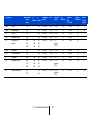
Reliability data
These data are based on feedback from experience in the field. The analysis of
the information recorded during maintenance by our technical team has enabled
us to determine the following Probabilities of Failure on Demand under normal
conditions of use:
Type of gas
LEL
(*)
Measurement
principle
SIL
Capability
λDU
PFDAVG
Test
period
Catalytic (VQ1)
SIL 2
1,89 10-7
8,3 10-4
12
months
-6
SFF
92,9%
-3
0.81 10
3 months
60% to
90%
Oxygen
Electrochemical
SIL 2
0,74 10
(*)
Electrochemical
SIL 2
1,09 10-6
1,19 10-3
3 months
60% to
90%
(*)
Electrochemical
SIL 2
2,98 10-6
3,26 10-3
3 months
60% to
90%
(*)
Electrochemical
SIL 2
4,48 10-6
4,91 10-3
3 months
60% to
90%
CO
H2S
NH3
(*) certification pending
64
OLC(T) 100
User manual
Special conditions of use
In case of exposure above the measuring range, it is mandatory to
bump test the instrument with gas and/or to perform a calibration.
In the event of a change of position, it is necessary to re-calibrate
the detector.
OLCT 100 IS (intrinsic safety mode of protection)
The detector must be powered by an intrinsically safe source.
The detector input characteristics on the J3 power plot are:
Ui = 28V, Ii = 93.3 mA, Ci = 39.2 nF, Li = 0
Ci = 2.39 µF with Ui = 10.5V, Ci = 4.32µF with Ui = 8.6V
The detector may be opened in a gaseous explosive zone (dusty non-explosive)
only to change the sensor block or for maintenance or to connect a compatible
intrinsically safe voltmeter with the following characteristics:
Certified for use in explosive atmospheres (Group IIC), no generator of
current or voltage
Ui max <= 28V; Ii max <= 93.3 mA
Li ≤ 3.5 mH
Ci ≤ 44 nF under 28V ; Ci ≤ 20 nF under 10.5 V ; Ci ≤ 0.88 µF under
8.6V
Appendix
65
66
OLC(T) 100
User manual
Appendix | Ordering information
Gas List
Please find below the list of gases that the OLC/OLCT 100 detector can detect.
Gas Code
Gas
001
002
003
004
005
006
007
008
009
010
011
012
013
014
015
016
017
018
019
020
021
022
023
024
025
026
027
028
029
030
031
032
Methane 0-100 % LEL
Methane 0-100% LEL (4.4% vol)
Hydrogen 0-100% LEL
Butane 0-100% LEL
Propane 0-100% LEL
Ammoniac 0-100% LEL
Ethyl Acetate 0-100% LEL
Butyl Acetate 0-100% LEL
Methyl acetate methyle 0-100% LEL
Acetone 0-100% LEL
Acetonitrile 0-100% LEL
Acetylene 0-100% LEL
Acrylic acid 0-100% LEL
Acroleine 0-100% LEL
Butyl acrylate 0-100% LEL
Ethyl Acrylate 0-100% LEL
Acrylonitrile 0-100% LEL
Benzene 0-100% LEL
1.3-Butadiene 0-100% LEL
Butanol (isobutanol) 0-100% LEL
2-Butanone 0-100% LEL
Cumene 0-100% LEL
Cyclohexane 0-100% LEL
Cyclohexanone 0-100% LEL
Dimethylether 0-100% LEL
Dodecane 0-100% LEL
Ethane 0-100% LEL
Ethanol 0-100% LEL
Ether (diethylether) 0-100% LEL
Ethylene 0-100% LEL
Formaldehyde 0-100% LEL
LPG 0-100% LEL
Appendix
67
Gas Code
Gas
033
034
035
036
038
039
040
041
042
043
044
045
046
047
048
049
050
051
052
054
055
056
057
058
059
060
064
065
066
200
203
204
205
213
214
215
216
217
218
219
220
Diesel 0-100% LEL
Natural gas 0-100% LEL
Heptane 0-100 % LEL
Hexane 0-100% LEL
Isobutane 0-100% LEL
Isobutene 0-100% LEL
Isopropanol 0-100% LEL
Kerosene (JP4) 0-100% LEL
Methyl Methacrylate 0-100% LEL
Methanol 0-100% LEL
Methylamine 0-100% LEL
Naphta 0-100% LEL
Naphtalene 0-100% LEL
Nonane 0-100% LEL
Octane 0-100% LEL
Ethylene Oxide (epoxyethane) 0-100% LEL
Propylene Oxide (Epoxypropane) 0-100% LEL
Pentane 0-100% LEL
Propylene 0-100% LEL
Styrene 0-100% LEL
Gasoline Lead free 0-100% LEL
Toluene 0-100% LEL
Trimethylamine 0-100% LEL
White spirit 0-100% LEL
Xylene 0-100% LEL
Methane 0-100% volume
MIBK 0-100% LEL
HFO 0-100% LEL
DMA 0-100% LEL
Oxygen O2 (electrochemical) 0-30% vol
CO, 0-100 ppm
CO, 0-300 ppm
CO, 0-1,000 ppm
H2S, 0-30 ppm
H2S, 0-100 ppm
H2S, 0-1,000 ppm
NO, 0-100 ppm
NO, 0-300 ppm
NO, 0-1,000 ppm
NO2, 0-10 ppm
NO2, 0-30 ppm
68
OLC(T) 100
User manual
Gas Code
Gas
221
222
223
224
225
227
228
229
230
231
232
233
235
239
240
241
242
243
244
245
246
247
248
249
250
251
252
253
254
255
256
257
258
500
501
502
503
504
505
506
507
SO2, 0-10 ppm
SO2, 0-30 ppm
SO2, 0-100 ppm
Cl2, 0-10 ppm
H2, 0-2,000 ppm
HCl, 0-30 ppm
HCl, 0-100 ppm
HCN, 0-10 ppm
HCN, 0-30 ppm
NH3, 0-100 ppm
NH3, 0-1,000 ppm
NH3, 0-5,000 ppm
ClO2, 0-3 ppm
CO2, 0-5%
CO2, 0-10 % volume
CO2, 0-100 % volume
PH3, 0-1 ppm
AsH3, 0-1 ppm
ETO, 0-30 ppm
SiH4, 0-50 ppm
COCl2, 0-1 ppm
Formaldehyde, 0-50 ppm
ETO, 0-100 ppm
H2S, 0-5000 ppm
Methanol, 0-1000 ppm
N2H4, 0-1 ppm
CO2, 0-5000 ppm
Ethyl Mercaptant, 0-100 ppm
Dimethyl sulfide, 0-100 ppm
HBr, 0-30 ppm
HBr, 0-100ppm
BCl3, 0-10 ppm
F2, 0-5 ppm
R12, 0-1% volume
R22, 0-2,000 ppm
R134a, 0-2,000 ppm
R141, 0-2,000 ppm
R142b, 0-2,000 ppm
R11, 0-1% volume
R23, 0-1% volume
Dichloromethane, 0-500 ppm
Appendix
69
Gas Code
Gas
508
509
510
511
512
513
514
515
516
517
518
519
656
657
658
659
660
661
662
Chloromethane (Methylchloride), 0-500 ppm
R123, 0-2,000 ppm
FX56, 0-2,000 ppm
R143a, 0-2,000 ppm
R404a, 0-2,000 ppm
R507, 0-2,000 ppm
R410a, 0-1,000 ppm
R32, 0-1,000 ppm
R227, 0-1% volume
R407c, 0-1,000 ppm
R408a, 0-4,000 ppm
R407f, 0-1000ppm
Ethanol, 0-500 ppm
Toluene, 0- 500 ppm
Isopropanol, 0-500 ppm
2-Butanone (MEK), 0-500 ppm
Xylene, 0-500 ppm
Styrene, 0-500 ppm
HFO, 0-1000ppm
To know you part number, please follow these instructions:
70
OLC(T) 100
User manual
Appendix
71
The Fixed Gas Detection Experts
EUROPEAN PLANT AND OFFICES
Z.I. Est – rue Orfila CS 20417 – 62027 Arras Cedex FRANCE
Tel: +33 (0)3 21 60 80 80 – Fax: +33 (0)3 21 60 80 00
Website: http://www.oldhamgas.com
AMERICAS
Tel: +1-713-559-9280
Fax: +1-281-292-2860
[email protected]
ASIA PACIFIC
Tel: +86-21-3127-6373
Fax: +86-21-3127-6365
[email protected]
EUROPE
Tel: +33-321-608-080
Fax: +33-321-608-000
[email protected]