1
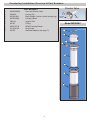
Multipure
®
Multipure Drinking Water Systems
Aquaperform Owner's MAnuAl
For Model Nos. MP880SC, MP880SB, MP880SI and MP880EL
Please retain this manual for future reference.
Multipure International l P.O. Box 34630 l las Vegas, nV 89133-4630 l
Phone 702.360.8880 l Toll-Free 800.622.9206
www.multipure.com
Multipure Drinking Water Systems
Thank you for selecting a Multipure Drinking water system to meet your need for quality drinking water. You have
acquired one of the finest drinking water treatment devices available for the reduction of a wide array of contaminants.
we are confident that your Multipure system will make a difference in your life. Thank you for your business.
Table of Contents
About
3
Before You Begin
3
Specifications
3
Below Sink Installation Overview and Part Numbers
4
Countertop Installation Overview and Part Numbers
5
1.
2.
3.
4.
5.
Installation Preparation
1.1: Installing the Filter Cartridge (universal)
1.2: locating the Approriate Installation Instructions
6
7
Countertop Installation
2.1: Connecting the Hose and Diverter Valve to the Faucet
2.2: Preparing and Operating Your Drinking water system
7
8
Below Sink Installation
3.1: required Installation Tools
3.2: Installing the Faucet
3.2-a: Drilling the Faucet Hole
3.2-b: Installing the standard Faucet
3.2-c: Installing the Capacity Monitor Faucet
3.3: Connecting to Your Plumbing
3.4: Connecting the Tubing to the Housing
3.5: Placing the system under the sink
3.6: Installing the system for Inline use
3.7: Preparing and Operating Your Drinking water system
8
9
9
10
11-13
13-14
15-16
17
18
18
Maintenance
4.1: regarding Filter Capacity
4.2: removing the Old Filter
4.3: Installing the new Filter
4.4: resetting the Capacity Monitor or Changing the Batteries
4.5: Flushing / Disinfecting the system
19
19
19
20
20
Additional Information
5.1: warranty
5.2: Performance Certifications
5.3: Performance Data sheet
5.4: California Certification
5.5: Troubleshooting
5.6: Frequently Asked Questions
20
21
22-24
25
26
27
2
About the Aquaperform Drinking Water System
•
•
•
The Multipure Aquaperform Drinking water system (Model# MP880) is designed for use on the countertop next to the sink,
below the sink, or inline with other devices. It can connect to the existing faucet or to the water source below the sink.
The Aquaperform includes all the accessories and fittings required for installation (except for the MP880sI Inline unit).
If installation or operation assistance is required, please contact your Multipure Independent Distributor. If the Independent
Distributor is unavailable, please contact Multipure Customer service at 800.622.9206.
Before You Begin
Multipure Drinking water systems (Dws) have been extensively tested and certified by nsF International to provide the highest
level of assurance that the device will perform as claimed. Please read this manual before proceeding with the installation and
use of your system. Installation, operation, and maintenance requirements are essential to the performance of your system –
failure to follow any instructions or operating parameters contained herein may lead to product damage or product failure.
•
•
•
•
•
•
•
replacement filters can be purchased directly from Multipure. For the latest prices, please visit our website at
http://www.multipure.com/store/.
Actual filter life depends on the amount of water used and the level of impurities in the water. See 4.1: Regarding Filter
Capacity for additional details.
Multipure Drinking water systems are not intended for use with microbiologically unsafe water or non-municipally-treated
water. systems certified for cyst reduction may be used on disinfected waters that may contain filterable cysts. See 5.5:
Frequently Asked Questions for additional details.
Do not allow water to freeze in the system. If the system is exposed to freezing temperatures, drain water from the system
and remove the filter. Allow the filter to thaw before replacing and reusing.
Do not allow water to sit in the system for extended periods of time (e.g., 10 days or more) without use. See 4.5: Flushing /
Disinfecting the System for additional details.
To dispose of the used filter, remove it from the housing and place in normal refuse. Filters disposed in a normal landfill will
not release any chemical contaminants and may continue to adsorb additional contaminants in the landfill.
Check for compliance with any state or local laws and regulations before use.
Specifications
3
Below Sink Installation Overview & Part Numbers
Item # Part #
Part Description
Item # Part #
Part Description
1
MC652
2
3
MC780
MC720
4
MC720
8
9
10
11
12
13
MC253AsBl
MC126
MC351
MCB7.5D-18
011-25-4100
MC232rH
5
6
7
MCl500
MC252-BlK
CB11As
Faucet assembly with blue tubing
attached
wing nut
Outlet adapter - connects to blue
tubing attached to faucet
Inlet adapter - connects to clear
tubing
Housing top
Black rubber Cushion (inside housing top)
Carbon Block Filter
14
MC920lF
V-band with knob
Bracket
O-ring
Housing bottom
Acrylic sleeve*
Clear tubing -connects inlet adapter to
plumbing
Adapta Valve
Connect clear tubing to plumbing -- Option A or B
Note: the Aquaperform MP880sI Inline unit does not inlcude the following
parts: faucet assembly (#1), wing nut (#2), outlet adapter (#3), inlet
adapter (#4), sleeve (#12), clear tubing (#13), adapta valve (#14)
1
13
2
OR
tubing
from faucet
3
B.
A.
4
5
water supply line with
Adapta Valve in 3/8” configuration
6
water supply line with
Adapta Valve in 1/2” configuration
7
8
9
v-band
knob
10
14
1/2” slip joint nut
riser
11
1/2” slip joint nut
14
Adapta Valve
3/8” configuration
12
riser
3/8” slip joint nut
angle stop valve
*
Adapta Valve
1/2” configuration
The acrylic sleeve (Item#12) is an optional part available for purchase.
4
angle stop valve
Countertop Installation Overview & Part Numbers
Diverter Valve
Part Numbers
1.
2.
3.
4.
5.
6.
7.
8.
9.
MC6400AsBl
MCl500
MC252-BlK
MC253AsBl
CB11As
MC351
MCB7.5D-18
011-25-4100
MC700
Hose and Diverter Valve
Housing Top
Black rubber Cushion (inside housing top)
locking V-Band
Arsenic Filter
O-ring
MP880 Housing Bottom
Acrylic base
standard Adapters (see page 7*)
1
Diverter
Valve
Hose
Model MP880SC
1
2
3
4
5
6
7
8
5
1.
INSTALLATION PREPARATION
Before beginning, inspect your Dws to confirm that it has been
received in good condition and that all parts are included (refer to the
specific installation section for the parts list). Perform the following
instructions prior to system installation.
should you require assistance, please contact your Independent
Distributor; if she/he is not able to help you, please feel free to contact Multipure's Customer service Department directly at
800.622.9206.
Model MP880SB
1.1: Installing the Filter Cartridge
1. If you have not done so already, remove the plastic wrapper and instruction wrap from around the filter.
2. with the Dws housing in an upright position, unscrew the black knob on the locking V-Band by turning it
counter- clockwise.
3. with the black knob removed, spread the locking V-Band apart and lift up and off of
top
the Dws. Carefully set it aside.
rubber
4. lift the top half of the Dws off of the bottom half. Make sure that the black O-ring
cushion
remains in place on the bottom half of the housing.
V-Band
5. Align the threaded hole of the filter cartridge onto the inside thread of the top half of
the Dws. rotate the cartridge clockwise to tighten; the cartridge typically requires four
to five revolutions to tighten adequately. Make sure that the cartridge is threaded
properly and straight. DO nOT OVerTIGHTen.
6. reconnect the top half of the Dws (with attached filter cartridge) with the bottom half.
V-Band
Knob
replace the locking V-Band, making sure the screw is in place to connect the band
turn to
together.
connect
7. screw the black knob onto the locking V-Band, turning it clockwise to tighten.
8. Make sure that the locking V-Band is secured tightly and evenly around the top and
bottom halves of the Dws housing.
6
1.2: Locating the Appropriate Installation Instructions
1.
2.
2.
Determine your installation type (e.g., countertop, below sink, inline).
Proceed to the instructions for your installation type:
a.
For Countertop Installation, proceed to section 2. Countertop Installation.
b.
For Below sink Installation (with or without a capacity monitor), proceed to section 3. Below Sink Installation.
c.
For Inline Installation, proceed to section 3.6: Installing the System for Inline Use.
Countertop Installation
when installing on a countertop, the Aquaperform sits atop its included acrylic base on the counter next to the sink. It connects
to the existing faucet via a dual-hose diverter valve. Follow these instructions to connect the Aquaperform for countertop use.
2.1: Connecting the Hose and Diverter Valve to the Faucet
1. remove the aerator or screen (if present) from the end of the faucet. If facing
the open end of the spout, rotate the aerator counter-clockwise to loosen and
remove.
2. Thread the diverter valve and hose through the acrylic base. set the system
housing (with the diverter valve and hose facing downward) onto the acrylic base.
3. Attach the diverter valve directly to the faucet spout. If the threads of the diverter
valve do not match the threads of the faucet, use one of the included faucet
adapters to connect the diverter valve and faucet. If facing the open end of the
spout, rotate the diverter valve and/or adapter clockwise to tighten.
NOTE: when using a faucet adapter, the rubber washer in the adapter always
faces up toward the faucet.
a.If Your Faucet Has an Outside Thread (male connector):
For many faucets with an outside thread, the diverter valve can attach directly
to the faucet. If the diverter valve is too small to attach to the faucet, attach the inside thread (female connector)
adapter, part# MC106, to the faucet, and then attach the diverter valve to the adapter.
b.If Your Faucet Has an Inside Thread (female connector):
The diverter valve cannot directly connect to a faucet with a female connector. Attach one of the outside thread (male
connector) adapters, part# MC107 or part# MC108, to the faucet, and then attach the diverter valve to the adapter.
MC107 is designed to fit larger faucets, and MC108 is designed to fit smaller faucets.
c.If Your Faucet requires More room for the Diverter Valve Connection:
some faucets, particularly sprayer hose faucets, require additional room for the diverter valve connection. If this
applies, attach the long adapter, part# MC257, to the opening of the faucet spout/sprayer, and then attach the diverter
valve to the adapter. The Dws may need to be repositioned on the sink to allow enough room for sprayer faucet use.
d.If the Adapters Do not Fit Your Faucet:
Although the adapters included with your Dws allow connections with many standard faucets, they do not cover
every type of available faucet connection. If none of the adapters allow the diverter valve to connect to your faucet,
please contact Multipure Customer service at 1.800.622.9206, ext. 175, to request part# MC105, part# MC109, or
part# MC719 as possible adapter solutions.
4. when connected properly, the hose from the diverter valve should lead toward the back of the faucet and sink.
5. The diverter valve features a bypass lever with a button on the left and right sides of the diverter valve. Press the left
button to bypass the Dws and select the unfiltered water spout (larger opening). Turn on your faucet to let unfiltered water
flow out of the diverter valve and to make sure that the diverter valve is properly connected.
6. Turn off the faucet.
existing
Faucet
*MC106
*MC107
swivel
Bypass
lever
Attachment
ring
*MC108
Hose
*MC257
Diverter Valve
Diverter Valve Attachment
Diverter Valve Attachment
with adapter
7
*MC700 - Adapters (choose one)
Many installations do not
require an adapter
2.2: Preparing and Operating Your Drinking Water System
1. using a paper towel or cloth, dry off all connections and the Dws housing.
2. Make sure that all connections are tightly secured.
3. Purge any air from the unit.
a. Press the right button on the diverter valve to select the filtered water spout.
The water will flow through the Dws and emerge from the smaller opening on
the diverter valve.
b. Allow water to flow through the Dws and filtered water spout for five minutes.
c. Press the left button to select the unfiltered water spout, and then turn off the
faucet.
4. Make sure that all connections are tightly secured and that there are no leaks.
5. Turn on the faucet and press the right button to select the filtered water spout.
6. Allow water to flow through the Dws and filtered water spout for approximately
30 minutes. This will flush the filter prior to use.
7. Press the left button to select the unfiltered water spout.
8. Turn off the faucet.
9. Check all connections to make sure that there are no leaks.
10. The system is now ready for use.
3.
bypass
lever
Below Sink Installation
The Aquaperform models MP880sB and MP880el are designed for use below the sink and can be installed on the incoming cold water line. The MP880sB and MP880el systems are connected to a specially designed faucet which installs
directly on the sink.
3.1: Required Installation Tools
The following tools are required to install your Aquaperform for belowsink use:
1. Installing the faucet on a ceramic/porcelain sink:
a.
3/8” reversible electric drill
b.
7/16” (or 1/2") high speed steel drill bit
c.
1/2" carbide-tipped masonry drill bit
d.
hammer
e.
center punch
f.
8” adjustable wrench
g.
pliers/locking pliers
2. Installing the faucet on a stainless steel sink:
a.
everything from list #1, plus 1/8” high speed drill bit
3. Installing the Adapta Valve:
a.
8” adjustable wrench
b.
wire cutter or knife
Model MP880SB
8
3.2: Installing the Faucet
The Aquaperform faucet can be installed through a standard faucet hole or spray hose
hole in your sink, if one is available. If no hole is available, refer to section 3.2-a:
Drilling the Faucet Hole. note that there are separate sections for installing a faucet
with or without a capacity monitor.
Proceed to the instructions for your installation type:
1. For a standard faucet, proceed to section 3.2-b: Installing the Standard Faucet.
2. For a capacity-monitored faucet, proceed to section 3.2-c: Installing the Capacity
Monitor Faucet.
3.2-a: Drilling the Faucet Hole
1. select and mark the faucet mounting spot on the sink.
a. Confirm that there are no reinforcing ribs under the desired faucet location.
b. If you have an extra hole in your sink for a spray hose, you may also choose to disconnect the spray hose and use
that existing hole for the Dws faucet.
2. use the hammer to gently tap the center punch on the sink location where the hole is to be drilled.
This creates an indentation marking the location to drill.
If You Have a Porcelain, Ceramic, or Cast Acrylic Sink:
CAuTIOn: Porcelain, ceramic, and cast acrylic surface materials are extremely hard and can crack or
chip quite easily. use extreme caution when drilling. Multipure is not responsible for any damages
resulting from faucet installation.
Mark the spot
nOTe: If you are installing a capacity monitor, you MusT use the 1/2" high-speed steel drill bit for step 2.
1. use the 1/2" carbide-tipped masonry drill bit to grind away the porcelain down to the metal, clearing
away enough porcelain to allow drilling without damaging the porcelain surface.
2. Carefully use the 7/16” (or 1/2”) high-speed steel drill bit to completely drill a hole through the metal
sink. CAuTIOn: Do not allow the drill bit to “grab” the porcelain, as this will damage the surface.
If You Have a Stainless Steel or Metal Sink:
nOTe: If you are installing a capacity monitor, you MusT use the 1/2"
high-speed steel drill bit for step 2.
1. use the 1/8” high-speed drill bit to drill a pilot hole.
2. use the 7/16” (or 1/2") high-speed steel drill bit to completely drill a hole
through the metal sink.
Note: For drilling a hole in your countertop,
please consult with the countertop manufacturer.
9
Carefully grind
away porcelain
3.2-b: Installing the Standard Faucet
Complete Faucet Assembly
with Blue Tubing
MC652
small black washer
Cover Plate
large black washer
COUNTERTOP
Plastic Washer
Lock Washer
Wing Nut
Blue Tubing
NOTE: The blue plastic tubing is attached to the faucet.
1. From the sink / countertop:
a.
Place the larger soft black rubber washer over the faucet hole.
b.
Place the cover plate on top of the large washer.
c.
Place the smaller soft black rubber washer on top of the cover plate.
d.
Place the faucet base over the smaller soft black rubber washer and atop the cover plate.
2. From under the sink:
a.
slide the hard plastic black washer (with the smaller side up) upward over the blue tubing.
b.
slide the lock washer upward, below the hard plastic washer.
c.
slide the wing nut upward, below the lock washer.
d.
Hand-tighten the wing nut to secure the faucet.
10
3.2-c: Installing the Capacity Monitor Faucet
when the Aquaperform is installed with a capacity monitor, the DigiFlow 5000V Capacity Monitor (MC993) flashes red when
the filter should be changed. Two AAA batteries (not included) are required for capacity monitor operation. The Capacity
Monitor consists of two main parts, the leD Display Plate that sits below the faucet, and the Filter Monitor unit (FMu) that
connects in-line between the drinking water system housing and the faucet.
Faucets with Capacity
Monitor include:
Installation Overview
1
2
3
4
5
6
7
8
9
10
11
12
13
14
15
Countertop
black wire from capacity
indicator plate
tubing from
housing
tubing from
faucet
spout
faucet handle
faucet base
faucet stud
tubing (blue) attached to faucet
smaller rubber washer
leD display plate
black wire (attached to #7)
larger rubber washer
black track washer
hard plastic black washer
lock washer
wing nut
filter monitor unit
two adapters (MC744)
Filter Monitor unit
NOTE: In addition to the blue plastic tubing attached to the faucet.
A separate piece of blue tubing is included for connection between the
housing OUTLET port and the Filter Monitor Unit.
1
1. From the sink / countertop:
a. Place the leD Display Plate (#7) over the faucet hole.
b. Feed the attached black wire (#8) down through the faucet hole. rotate
the leD Display Plate so that the indicator light will be easy to see.
c. Place the faucet base (#3) on top of the leD Display Plate. Feed the blue
tubing and faucet stud down through the hole in the sink. The faucet stud
should now be accessible below the sink.
2. From under the sink:
a. slide the black track washer (#10) (with the flat side down) upward over
the threaded faucet stud. Guide the black wire (#8) from the leD Display
Plate through the track to protect the wire and prevent it from becoming
pinched between the sink and the stud nut.
b. slide the hard plastic black washer (#11) upward over the blue tubing (#5),
and faucet stud (#4).
c. slide the lock washer (#12) upward over the faucet stud, below the black
plastic washer.
d. screw on the stud wing nut (#13) below the lock washer.
e. Hand-tighten the wing nut to secure the faucet.
2
3
6
9
countertop
4
7
countertop
10
8
11
12
13
5
14
5
15
15
Capacity Monitor
Assembly
11
3.2-c: Installing the Capacity Monitor Faucet
(continued)
Connect the Tubing to the Filter Monitor Unit
Capacity Monitor Assembly
nOTe: Complete this step only after the Dws tubing has been connected in
section 3.4: Connect the Tubing to the Housing.
1.
2.
3.
4.
Connect the two tube fittings (#15) (MC744) to the Filter Monitor unit (#14)
(FMu) by threading them into the threaded ports, one on each side
(tighten securely, but do not over-tighten).
The FMu can be mounted either horizontally or vertically, but vertical
installation is recommended. nOTe: The FMu will function with water flow
in either direction.
Fully insert the blue plastic tubing (#5) from the Dws OuTleT into one
side of the FMu.
Fully insert the blue plastic tubing (#5) from the faucet into the other
side of the FMu.
nOTe: when pushing the tubing into the fitting, you will encounter some resistance.
This does not mean that the tube is fully inserted. Continue to push firmly until the
tubing is inserted as far as possible (roughly 5/8” into the fitting).
Insert blue tubing 5/8”
14
15
15
5
INLET
from housing
OUTLET
to faucet
Pull to check that the
tubing is secure.
Insert tubing and push
until you feel resistance
-- at this point, the
tubing is not fully
inserted. Push firmly
until the tubing is
inserted as far as
it will go.
Set up the Filter Monitor Unit
2.
3.
4.
5.
6.
7.
Connect the black wire (#8) from the leD Display Plate into the Filter Monitor
unit (#14).
Open the top of the FMu and insert two (2) AAA batteries (not included) into the
battery compartment, making sure to match the + and – signs. Close the battery
compartment.
There will be a long audio sound, and the leD will blink green for two seconds,
and then blink green five times.
After installing the batteries, press the check/reset button to confirm the leD is
functioning.
Press and hold the check/reset button on the Filter Monitor unit (FMu) for three
(3) seconds. You should hear a long audible sound.
The leD on the leD Display Plate will blink green for one (1) second with an
audible sound, then blink green and red for one (1) second each, and then blink
green five (5) times twice. The remaining capacity and time is now reset to the
original capacity.
Peel off the paper backing from the hook-and-loop connector strip, and attach
one piece to the back of the FMu. Peel off the paper backing from the second
hook-and-loop connector strip and attach it to the desired wall location. Attach the
FMu to the wall using the two hook-and-loop connector strips.
12
Adapter
OuTleT
insert
1.
tubing
3.2-c: Installing the Capacity Monitor Faucet (continued)
Reading the LED Display Plate
1. when you turn on the faucet, or when the button on the FMu is pressed, the leD on the leD
Display Plate blinks five (5) times to indicate the filter capacity status. The color of the leD indicates
the filter status:
a. Green = 30% - 100% filter capacity
b. Orange = 0% - 30% filter capacity
c. red = 0% filter capacity (the FMu will also play a long audible sound to indicate 0% capacity)
2. Multipure recommends ordering a new replacement filter (either online at
http://www.multipure.com/store/page6.html or by telephone at 800.622.9206) when the monitor
indicates 30% capacity or less.
3. The FMu will memorize the last remaining capacity in the event that the batteries lose power. It will restore the last
remaining capacity when new batteries are installed.
nOTe: As with all drinking water treatment devices which reduce certain contaminants by mechanical filtration, the capacity
of the filter can vary, and is dependent upon the type and level of contaminants in your water. If the system is used on water
with high levels of particulate matter, Multipure recommends the installation and use of an additional pre-filter element.
3.3: Connecting to Your Plumbing
Included with your MP880sB/MP880el Drinking water system is one installation kit, which includes all of the fixtures and
accessories needed to install your system below the sink. If you determine that your particular plumbing configuration
requires fixtures different from those included with your shipment, please contact Multipure’s Customer service office at
800.622.9206, ext. 175.
Determine Your Adapta Valve Configuration
If your residence has a cold water supply line with a 3/8” or 1/2" slip joint connection, you may use the Adapta Valve included with your system to connect your Dws to the plumbing. The Adapta Valve assembly (MC922AsBl) includes both the
valve and threading adapter.
Adapta Valve
(#14)
Threading adapter
NOTE: When attaching the Adapta Valve to straight pipe
threads, use Teflon tape on the threads. Wrap the tape around
the pipe only once.
1/2” slip joint nut
1/2” slip joint nut
Adapta Valve
1/2” configuration
riser
riser
3/8” or 1/2” slip joint nut
1/2” slip joint nut
Adapta Valve
3/8” configuration
riser
3/8” slip joint nut
angle stop valve
angle stop valve
water supply line
before installation
A.
water supply line with
Adapta Valve in 3/8” configuration
13
angle stop valve
B.
water supply line with
Adapta Valve in 1/2” configuration
Adapta Valve Installation (continued)
1. using the 3/8” configuration:
a. The 3/8” configuration is used on a water supply line with a 3/8” slip joint.
b. The 3/8” configuration is typically installed at the bottom of the riser at the angle stop valve.
2. using the 1/2" configuration:
a. The 1/2" configuration can be used at either the top of the riser at the faucet pipe
or at the bottom of the riser at the angle stop valve.
b. Install the 1/2" configuration at the top of the riser on a water supply line that does
not have a slip joint nut at the angle stop valve.
c. Install the 1/2" configuration at the angle stop valve if there is a 1/2" slip joint nut
there.
3/8”
configuration
1/2”
configuration
Install the Adapta Valve
nOTe: The Adapta Valve must be installed on the cold water line only.
1. shut off the cold water supply to the faucet by rotating the angle stop valve clockwise until the water flow is off. Place a
catch basin or other container below the faucet to catch any residual water in the pipes.
2. Disconnect the cold water riser/supply line at the angle stop valve or cold water faucet pipe. use an 8” adjustable wrench
to rotate the slip joint nut counterclockwise until the riser/supply line and slip joint nut detach from either the angle stop
valve or the faucet pipe.
3. Connect the Adapta Valve to the pipe from which you removed the slip joint nut.
a. Align the Adapta Valve to either the angle stop valve or cold water faucet pipe, making
sure that the rubber washer is in place in the Adapta Valve.
b. use an 8” adjustable wrench to rotate the connection clockwise until tight. DO nOT
OVerTIGHTen.
4. Connect the cold water riser/supply line with the slip joint nut to the Adapta Valve.
a. Align the slip joint nut to the Adapta Valve.
b. use an 8” adjustable wrench to rotate the slip joint nut clockwise until tight. DO nOT OVerTIGHTen.
c. Make sure that the supply line does not block the shutoff valve on the side of the Adapta Valve. If necessary, trim the
supply line before reconnecting.
5. Connect the 1/4" clear plastic tubing (included with the system) to the Adapta Valve.
a. using wire cutters or a knife, cut (square cut) the tip end off of the clear plastic tubing. Do not use scissors.
b. Insert the tubing fully into the opening of the shutoff valve on the side of the Adapta Valve; the tubing should typically
be inserted 5/8” into the adapter.
Insert clear tubing 5/8”
nOTe: when pushing the tubing into the opening, you will encounter some resistance. This does not mean that the tube is
fully inserted. Continue to push firmly until the tubing is inserted as far as possible (roughly 5/8” into the adapter).
Push the tubing into the small hole
as far as it will go. Pull to check
secure.
6. Confirm that the unit shutoff Valve attached to the Adapta Valve is in the OFF position by rotating the handle clockwise
until it stops.
7. Proceed to section 3.4: Connecting the Tubing to the Housing to connect the clear plastic tubing to the Dws.
14
3.4: Connecting the Tubing to the Housing
OuTleT
Attach the Adapters to the Housing
InleT
1. Connect the included Inlet adapter (MC720) to the system housing’s labeled Inlet port.
rotate the adapter clockwise, first by hand, then using a wrench, to tighten onto the
system.
2. Connect the included Outlet adapter (MC720) to the system housing’s labeled Outlet
port. rotate the adapter clockwise, first by hand, then using a wrench, to tighten onto
the system.
Housing Top
Connect the Tubing to the Outlet Port
1. using wire cutters or a knife, cut (square cut) the tip end off of the blue plastic tubing
(either connected to the faucet or a separate piece included with the Capacity Monitor).
Do not use scissors.
2. Fully insert the tubing into the adapter on the OuTleT port of the system housing; the
tubing should typically be inserted 5/8” into the adapter.
Adapter
blue tubing
OuTleT
nOTe: when pushing the tubing into the adapter, you will encounter some resistance.
This does not mean that the tube is fully inserted. Continue to push firmly until the tubing
is inserted as far as possible (roughly 5/8” into the adapter).
Insert blue tubing 5/8”
3. Pull on the tubing to make sure that it is securely connected.
Insert tubing and push until you
feel resistance -- at this point,
the tubing is not fully inserted.
Push firmly until the tubing is
inserted as far as it will go.
C o n n e c t t h e Tu b i n g t o t h e I n l e t P o r t
1. using wire cutters or a knife, cut (square cut) the tip end off of the clear plastic tubing con
nected to the Adapta Valve. Do not use scissors. Do not cut more than 1/2" off of the
end of the clear plastic tubing.
2. Fully insert the tubing into the adapter on the InleT port of the system housing; the
tubing should typically be inserted 5/8” into the adapter.
adapter
clear tubing
InleT
nOTe: when pushing the tubing into the adapter, you will encounter some resistance.
This does not mean that the tube is fully inserted. Continue to push firmly until the tubing
is inserted as far as possible (roughly 5/8” into the adapter).
3. Pull on the tubing to make sure that it is securely connected.
Connecting to straight Adapter
Insert tubing and
push until you feel
resistance -- at this
point, the tubing is
not fully inserted.
Push firmly until the
tubing is inserted as
far as it will go.
15
Connecting to an Icemaker, Instant Hot Dispenser, or Other Device
use the following steps to connect the Dws to an icemaker, instant hot dispenser, or other device in addition to your
faucet or capacity monitor faucet. A Tee adapter (MC445)
is required.
nOTe: To connect your Dws to the icemaker, instant hot
dispenser, other device, you must have access to this
other device from your sink.
Blue tubing
1. using wire cutters or a knife, cut (square cut) the blue
plastic tubing 6” from where it is connected to the
OuTleT port of the Dws housing. Do not use
scissors.
2. Fully insert the blue plastic tubing from the Dws
OuTleT into the bottom port of the Tee adapter.
Push the tubing until you feel resistance, and then
continue to push firmly until it is inserted as far as it
will go.
Tee - MC445
(purchased separately)
Clear tubing - MC232RH
(purchased separately)
Connect to refrigerator
or other device.
Clear tubing
to plumbing
Faucet stud
3. Fully insert the blue plastic tubing from the faucet (or the tubing from the capacity monitor)
into the top port of the Tee. Push the tubing until you feel resistance, and then continue to
push firmly until the tubing is inserted as far as it will go.
4. Fully insert a separate 1/4" poly tube (available through Multipure or a plumbing supplier)
into the side port of the Tee. Provide sufficient tubing to reach your icemaker, instant hot
dispenser, or other device, and connect to that device.
Blue tubing
Tee
A
To refrig.
or other
device
Housing
top
unit with stainless steel Faucet
black wire from capacity
indicator plate
Faucet stud
Blue tubing
Tee
A
capacity monitor
assembly
To refrig.
or other
device
Housing
top
unit with Capacity Monitor Faucet
16
3.5: Placing the System Under the Sink
The Aquaperform models MP880sB and MP880el are designed to mount to the
cabinet wall beneath the sink. These systems can also sit on the cabinet floor with
the use of an optional acrylic base. If you would like to order the Aquaperform acrylic
base, please contact Multipure Customer relations at 800.622.9206, ext. 175.
nOTe: The Aquaperform Dws weighs approximately 7.5 lbs. with a dry filter; the
system weighs more when the filter is wet. Before mounting the system on the wall
under the sink, please confirm that the wall will support the weight of the system.
The mounting bracket (MC129) is included with the system.
Model MP880SB
1. Before installing the below-sink mounting bracket, make sure that enough room exists Back View
beneath the sink to remove the Dws from the bracket. You need several inches of
space both above and away from the mounting wall
worm clamp Top screws
2. Attach the mounting bracket to the wall:
a. Hold the bracket in place on the wall, making sure that the keyhole side is at the
top. use a pencil or other tool to mark the location for the mounting screws
through the keyholes.
b. screw in the mounting screws to the wall, making sure that you leave enough
space to hang and remove the bracket from the screws. nOTe: DO nOT install
screws for the bottom holes of the mounting bracket.
Key hole
c. Place the mounting bracket over the screws to make sure that it sits properly –
tight enough to hold the Dws stable, but loose enough to remove when
necessary.
Side View
3. remove the mounting bracket from the wall screws.
4. Open the two bracket bands:
a. use a slotted (flathead) screwdriver to turn the screw on the bracket band’s worm
slots
clamp counter-clockwise.
b. rotate the screw counter-clockwise until the band is fully open.
5. Thread each bracket band through the band slots on the mounting bracket:
a. slide the slotted end of one band through both sides of the top pair of band slots.
b. slide the slotted end of the other band through both sides of the bottom pair of
band slots.
6. wrap both bracket bands around the Dws housing top, above the locking V-Band.
7. Tighten the bracket bands:
a. Position the slotted end of the band at the mouth of its worm clamp opening.
b. Turn the worm clamp screw clockwise to tighten the band around the Dws housing. Tighten until the band is
secure.
c. repeat steps 7a and 7b for the other bracket band.
nOTe: Complete step 8 OnlY after all adapters and tubing are connected to the Dws.
8. Attach the Dws and bracket to the wall by hanging the bracket on the two installed wall screws (see step 2). Position
the larger holes of the bracket keyholes over the wall screws, and then slide the bracket down so that the screws rest
securely in the smaller holes of the bracket keyholes. Make sure that the Dws and bracket are fastened securely to
the wall before releasing your grip.
9. To remove the system for servicing, slide the Dws and bracket up, so that the wall screws are positioned at the larger
holes of the bracket keyholes. Pull the Dws and bracket away from the wall.
The MP8800sB, MP880sI and MP8800el units can also be placed "upside-down" in the acrylic sleeve. A notch has been
cut out of the sleeve to accommodate the tubing. In this configuration, it may be necessary to relieve air which builds up in
the stainless steel housing every two months.
To relieve the built-up air:
1.
Turn on the Multipure filtered water faucet
2.
with the faucet in the "on" position, and water flowing through it, pick up the stainless steel housing and turn it "right
side-up", so that the ports and tubing are now on top. You'll hear a "whooshing" sound come from the faucet as the
trapped air escapes through the open faucet. This should only take a few moments.
3.
Once water continues to flow out of the faucet, return the housing back to its "upside down" position and turn off the
faucet.
17
3.6: Installing the System for Inline Use
Multipure Inline models are ideal for refrigerators, water coolers, or restaurants where all water to a
cold water outlet or faucet is filtered. Model MP880sI includes the housing, filter, bracket, and
screws. The inline models are appropriate for an inline installation and can be used with your existing
faucet. It is recommended that the inline models be installed by a professional plumber in accordance
with established plumbing procedures.
3.7: Preparing and Operating Your Drinking Water System
1. using a paper towel or cloth, dry off all connections and the Dws housing.
2. Make sure that all connections are tightly secured.
3. Turn the water supply back on; rotate both the Adapta Valve shutoff valve and either the
water supply Angle stop Valve or water shutoff valve counter-clockwise to engage the
flow of water through the pipes.
4. Turn the handle on the Dws faucet to start the flow of filtered water.
5. Allow water to flow through the Dws and the faucet for five minutes. This purges any air
and loose carbon from the system.
6. Adjust the Angle stop Valve or water shutoff valve so that the water flow to the drinking
water faucet does not exceed the flow rate. nOTe: It takes approximately 20 seconds to
fill a quart at 1.0 gallons per minute flow rate.
7. Turn off the Dws faucet and check for leaks.
a.Check the V-Band to confirm that it is secured evenly around the top and bottom
housing halves.
b.Hand-tighten the black knob on the V-Band until it is as tight as possible.
8. Turn on the Dws faucet and allow water to flow for approximately 30 minutes. This will flush the filter and charge the
carbon.
9. Turn off the Dws faucet.
10. Check all connections to make sure that there are no leaks.
11. Congratulations! Your Dws is now ready for use.
If you have any questions regarding the installation of your
Multipure Drinking Water System, call:
Multipure International
Customer Service Department
7251 Cathedral Rock Drive
Las Vegas, NV 89128
702.360.8880 phone
800.622.9206 toll-free
702.360.8575 fax
email: [email protected]
www.multipure.com
18
4.
Maintenance
4.1: Regarding Filter Capacity
1. exact filter capacity varies in proportion to the amount of water used and the level of impurities in the water being
processed. For contaminants reduced through physiochemical adsorption, the filter capacity is 600 gallons. For
contaminants reduced through mechanical filtration, capacity claims are inapplicable due to broad variations in the quality
and quantity of physical matter in the drinking water. excessive physical matter will cause the Dws to clog, diminishing
flow rate but reducing the contaminants from the resultant water stream.
2. For optimum performance and to maintain the lifetime warranty on your system housing, it is essential that the filter be
replaced when the first of the following occurs: 1. annually, 2. when the system reaches its rated capacity, 3. when the
flow rate diminishes, or 4. when the filter becomes saturated with bad tastes and/or odors.
4.2: Removing the Old Filter
1. Before opening the Dws housing, place a pan or basin beneath the housing.
2. Disengage the water supply to the Dws by turning the Adapta Valve shutoff valve
clockwise or by turning the water supply shutoff valve clockwise.
3. Turn on the Dws faucet to relieve the water pressure in the system.
4. If the system is mounted on a bracket, remove the system from the bracket.
a.
Tilt the top of the system toward the wall.
b.
slide the locking V-Band up and into the upper bracket notch.
c.
slide the system out of the bracket.
5. with the Dws housing in an upright position, unscrew the black knob on the locking
V-Band by turning it counter-clockwise.
6. with the black knob removed, spread the locking V-Band apart and let it drop off the
bottom of the Dws. Carefully set it aside.
7. lift the top half of the Dws off of the bottom half. Make sure that the black O-ring
remains in place on the bottom half of the housing.
8. remove the old filter cartridge from the top half of the housing by rotating it counterclockwise (if facing the inside of the top half of the housing).
9. Dispose of the used filter in your waste container.
10.rinse out the inside of the system housing, hand washing if necessary.
11.Inspect the black rubber cushion on the inside of the top half of the housing, making sure
that it is not cracked or worn; Multipure recommends that the cushion be replaced every
two to three years.
keyhole
4.3: Installing the New Filter
1. If you have not done so already, remove the plastic wrapper and instruction wrap
from around the new filter.
2. Align the threaded hole of the new filter cartridge onto the inside thread of the top
half of the Dws. rotate the cartridge clockwise to tighten (if facing the inside of the
top half of the housing). Make sure that the cartridge is threaded properly and
straight. DO nOT OVerTIGHTen.
3. reconnect the top half of the housing (with attached filter cartridge) with the bottom
half. replace the locking V-Band, making sure the screw is in place to connect the
band together.
4. screw the black knob onto the locking V-Band, turning it clockwise to tighten.
5. Make sure that the V-Band is tightly secured evenly around the housing top and
bottom.
6. To resume normal use of the Dws, proceed to 3.7: Preparing and Operating Your
Drinking Water System.
19
turn to
remove
turn to
connect
4.4: Resetting the Capacity Monitor or Changing the Batteries
Resetting the Capacity Monitor
After changing the drinking water system filter, the capacity monitor must be reset to its original capacity.
1. Press and hold the check/reset button on the Filter Monitor unit (FMu) for three (3) seconds. You should hear a long
audible sound.
2. The leD on the leD Display Plate will blink green for one (1) second with an audible sound, then blink green and red
for one (1) second each, and then blink green five (5) times twice. The remaining capacity and time is now reset to the
original capacity.
Changing the Batteries
1. Open the top of the Filter Monitor unit and remove and discard the used batteries.
2. Insert two (2) fresh AAA batteries into the battery compartment, making sure to match the + and – signs. Close the
battery compartment.
3. There will be a long audio sound, and the leD will blink green for two seconds, and then blink green five times.
4. After installing the batteries, press the check/reset button to confirm the leD is functioning.
4.5: Flushing / Disinfecting the System
Multipure recommends that you not allow water to sit in the system for extended periods of time without use. If a unit is left
unused for more than 10 days, it may need to be flushed / disinfected before resuming normal use.
1.
2.
3.
4.
remove the filter by following the directions in 4.2: Removing the Old Filter.
Add 5 to 7 drops of bleach to the bottom half of the system.
reconnect the top half of the housing without a replacement filter installed.
Turn on the water supply and allow the system to fill up with the water/bleach solution.
a. Countertop systems:
i. Turn on the faucet, and press the right button on the diverter valve to select the filtered water spout.
ii. Once water begins to flow, press the left button to stop the filtered water spout.
iii. Turn off the faucet, and let the system soak for at least 30 minutes.
b. Below-sink systems:
i. remove the faucet spout and place it in a container with one quart of water and bleach (5 drops of bleach
per one quart of water).
ii. Allow the system and the faucet to soak for at least 30 minutes.
iii. Clean the inside of the faucet spout with pipe cleaners. You may also use a mild detergent, such as soft scrub®.
5. Flush and rinse the system.
a. Countertop systems:
i. with the faucet off, press the right button on the diverter valve to select the filtered water spout.
ii. let the water and bleach flush out of the system until the water flow stops.
iii. Open, clean, and rinse out the inside of the system housing.
iv. Follow the directions in 1.1: Installing the Filter Cartridge (Universal).
v. Follow the directions in 2.2: Preparing and Operating Your Drinking Water System.
b. Below-sink systems:
i. Disassemble the system housing and pour out the water/bleach solution. Clean and rinse out the inside of the
system housing.
ii.
Follow the directions in 4.3: Installing the New Filter.
5.
Additional Information
5.1: Warranty
Multipure 90-Day Guarantee: Multipure is confident in the performance of its Drinking water systems (Dws). If you
should find this Drinking water system unsatisfactory, let us know within 90 days of purchase for a prompt exchange or
refund.
Multipure Warranty: Multipure warrants to the original retail customer its Dws and components to be free of defects in
material and workmanship for use under normal care, and will repair or replace any system at no charge (excluding transportation to Multipure Corporate Headquarters) to the customer during the warranty period. The Dws housing is warranted
for a lifetime (provided the filter has been changed at least once per year); all exterior hoses and attachments to the Dws
are also warranted for defects in material and workmanship for one (1) year.
Multipure solid Carbon Block Filters are warranted for defects in material and workmanship for use under normal care. The
capacity of the filter cartridge depends upon the amount of impurities in the water to be processed.
except as otherwise expressly provided above, Multipure makes no warranties, express or implied, arising by law or otherwise, including without limitation the implied warranties of merchantability and fitness for a particular purpose, to any person. This limited warranted may not be altered, varied, or extended except by a written instrument executed by Multipure.
The remedy of repair or replacement as provided under this limited warranty is exclusive. In no event shall Multipure be
liable for any consequential or incidental damages to any person whether occasioned by negligence of the manufacturer,
including without limitation damages of loss of use, cost of substitution, property damage, or other monetary loss.
warranty is valid only if the Dws is operated within conditions listed herein. The warranty begins from the date of purchase.
20
5.2: Performance Certifications
Multipure Drinking Water Systems
Product Performance Tested and Certified
Multipure Drinking water systems have been tested and certified by nsF International to comply with
nsF/AnsI standards 42 and 53 for the reduction of specific contaminants being considered as established or
potential health hazards.
Standard 42, Aesthetic Effects
Standard 53, Health Effects
system tested and certified by nsF International against
nsF/AnsI standard 42 for the reduction of:
Chloramine
Chlorine taste and odor
nominal Particulate reduction, class I
system tested and certified by nsF International against
nsF/AnsI standard 53 for the reduction of:
Arsenic V
Asbestos
Chlordane
Cyst
lead
Mercury
MTBe
PCB
Toxaphene
Turbidity
VOC (listed below)
Volatile Organic Chemicals (VOC) includes:
Disinfection By-Products
chloropicrin
haloacetonitriles (HAn):
bromochloroacetonitrile
dibromoacetonitrile
dichloroacetonitrile
trichloroacetonitrile
haloketones (HK):
1,1-dichloro-2-Propanone
1,1-trichloro-2-Propanone
trihalomethanes (THMs; TTHMs):
bromodichloromethane
bromoform
chloroform
dibromochloromethane
tribromoacetic acid
Herbicides
alachlor
atrazine
2,4-D
dinoseb
pentachlorophenol
2,4,5-TP (silvex)
Chemicals
benzene
carbon tetrachloride
chlorobenzene
1,2-dichloroethane
1,1-dichloroethylene
cis-1,2-dichloroethylene
1,2-dichloropropane
cis-1,3-dichloropropylene
ethylbenzene
hexachlorobutadiene
hexachlorocyclopentadiene
simazine
styrene
1,1,2,2-tetrachloroethane
tetrachloroethylene
toluene
trans-1,2-dichloroethylene
1,2,4-trichlorobenzene
1,1,1-trichloroethane
1,1,2-trichloroethane
trichloroethylene
xylenes (total)
Pesticides
carbofuran
dibromochloropropane (DBCP)
o-dichlorobenzene
p-dichlorobenzene
endrin
ethylene dibromide (eDB)
heptachlor
heptachlor epoxide
lindane
methoxychlor
Claims of capacity are not applicable to contaminants
reduced by mechanical filtration because of broad variations in the quality and quantity of
physical matter in your drinking water.
Filter Model CB11As
21
5 . 3 : P e r f o r m a n c e D a ta S h e e t
Performance Data Sheet
Multipure Drinking water systems have been tested and certified under nsF/AnsI standard 53 as shown
below. The concentration of the indicated substances in water entering the system was reduced to a concentration less than or equal to the permissible limit for water leaving the system, as specified in
nsF/AnsI 53, Health effects.
For Model Nos. MP880SC, MP880SB, MP880SI, MP880EL
**Percent reduction reflects actual performance of Multipure product as specifically tested (at 200% of capacity, i.e. 1500 gallons).
Percent reduction shown for VOCs* reflects the allowable claims for Volatile Organic Chemicals/Compounds as per Tables.
Chloroform was used as a surrogate for VOC reduction claims, the Multipure Systems’ actual reduction rate of Chloroform was
>99.8% as tested (at 200% of capacity).
22
5 . 3 : Performance Data Sheet
(continued)
23
5 . 3 : Performance Data Sheet
(continued)
NSF/ANSI 42 - Aesthetic Effects
The system has been tested according to nsF/AnsI standard 42 for the reduction of the following substances. The concentration of the indicated substances in water entering the system was reduced to a concentration less than or equal to the
permissible limit for water leaving the system.
note: This addresses the u.s. environmental Protection Agency (ePA) Primary and secondary Drinking water regulations in effect at its time of publication, as they relate to Multipure’s performance in conformance to the industry performance criteria. These regulations are continually being updated at the
Federal level. Accordingly, this list of MCls will be reviewed and amended when appropriate. Please visit our website for list of product certifications.
NOTES:
Multipure Drinking water systems have been certified, as indicated, by nsF International for compliance to nsF/AnsI standard nos. 42 & 53.
The Multipure Drinking water systems have been certified by the state of California Department of Public Health for the reduction of specific
contaminants listed herein.
3. Chloroform was used as a surrogate for claims of reduction of VOCs. Multipure systems tested at >99.8% actual reduction of Chloroform. Percent
reduction shown herein reflects the allowable claims for VOCs as per tables in the standard.
4. Do not use with water that is microbiologically unsafe or of unknown quality without adequate disinfection before or after the system.
Systems certified for cyst reduction may be used on disinfected water that may contain filterable cysts.
5. Filter life will vary in proportion to the amount of water used and the level of impurities in the water being processed. For optimum performance, it is
essential that the filter be replaced on a regularly scheduled basis as follows: (a) annually; (b) when the unit’s rated capacity has been reached; (c)
the flow rate diminishes; or (d) the filter becomes saturated with bad tastes and odors.
6. Multipure Drinking water system Housings are warranted for a lifetime (provided that filter has been changed at least once per year). All exterior
hoses and attachments to the system are warranted for one year. Please see the Owner’s Manual for complete product
guarantee and warranty information.
7. Please see the Owner’s Manual for installation instructions and operating procedures.
8. In compliance with new York law, it is recommended that before purchasing a water treatment system, nY residents have their water supply tested
to determine their actual water treatment needs. Please compare the capabilities of the Multipure unit with your actual water treatment needs.
9. while testing was performed under standard laboratory conditions, actual performance may vary.
10. The list of substances which the treatment device reduces does not necessarily mean that these substances are present in your tap water.
1.
2.
24
5 . 4 : California Certification Department of Public Health
Facts About Arsenic (in compliance with nsF
standard 53)
Arsenic (abbreviated As) is a naturally occurring
contaminant found in many ground waters.
Arsenic in water has no color, taste, or odor,
and must be measured by lab testing. Public
water utilities must have their water tested for
arsenic, and their results can be obtained from
your local water utility. If you have your own
well, the water can be tested; your local health
department or state environmental health
agency can provide a list of certified testing
labs. Information about arsenic in water can be
found on the Internet at the u.s. environmental
Protection Agency website, at
http://www.epa.gove/safewater/arsenic.html.
There are two forms of arsenic: pentavalent
arsenic (also called As(V), As(+5), and arsenate) and trivalent arsenic (also called As(III),
As(+3), and arsenite). In well water, arsenic
may be pentavalent, trivalent, or a combination
of both. special sampling procedures are needed for a lab to determine what type and how
much of each type of arsenic is in the water.
Check with the labs in your area to see if they
can provide this type of service.
specially formulated Carbon Block systems are
very effective at removing pentavalent arsenic.
A free chlorine residual will rapidly convert trivalent arsenic to pentavalent arsenic. Other water
treatment chemicals such as ozone and potassium permanganate will also change trivalent
arsenic to pentavalent arsenic. A combined
chlorine residual (also called chloramine) may
not convert all the trivalent arsenic. If you get
your water from a public water utility, contact
the utility to find out if free chlorine or combined
chlorine is used in the water system.
The Multipure Aquaperform (MP880) Models
are designed to remove only pentavalent
arsenic. The Aquaperform will not convert trivalent arsenic to pentavalent arsenic. The system
may remove some trivalent arsenic, however, it
has not been evaluated for its ability to remove
trivalent arsenic. The system was tested in a
laboratory to remove pentavalent arsenic.
under lab conditions, as defined in AnsI/nsF
standard 53, the system reduced 0.050 mg/l
(ppm) pentavalent arsenic to 0.010 mg/l (ppm)
(the u.s. ePA standard for drinking water) or
less. The performance of the system may be
different at your installation. Have the treated
water tested for arsenic to check if the system
is working properly.
The Carbon Block filter component of the
Aquaperform system must be replaced as indicated in this Owner’s Manual to ensure the system will continue to remove arsenic and other
contaminants.
25
5 . 5 : Tr o u b l e s h o o t i n g
26
5.6: Frequently Asked Questions
27
Be sure to replace your filter at least once a year or sooner, if needed.
Date of Installation:________________________________________
Unit Model Number:_______________________________________
Filter Type:______________________________________________
Dates of Filter Change
To order a Replacement Filter
Call 800.622.9208
or
www.multipure.com/rf.htm
Multipure
7251 Cathedral rock Drive
las Vegas, nV 89128
800.622.9206 toll-free
702.360.8880 phone
702.360.8575 fax
[email protected]
Aquaperform Manual/1403