1
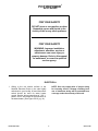
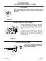
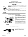
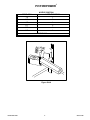
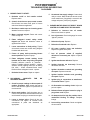
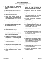
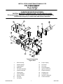
INSTALLATION & MAINTENANCE MANUAL FOR PVI FIREPOWER B40 OIL BURNER 1.0 thru 10.0 gph CARBON MONOXIDE WARNING: CAUTION: IMPROPER COMBUSTION MAY CAUSE SERIOUS INJURY. PVI recommends a seasonal or annual combustion check-out be performed by a qualified service agency to ensure safe and efficient operation. Typical Construction Figure 22A-1 1. 2. 3. 4. 5. 6. 7. 8. 9. 10. 11. PV500-22A 08-98 Burner housing Mounting flange Flange gasket Blast tube Oil nozzle assembly Ignition electrodes Housing plug Connecting pipe Electric oil valve Oil pump Oil strainer 12. 13. 14. 15. 16. 17. 18. 19. 20. 21. 1 Pump coupling Fan wheel Fan motor Flame safeguard Ignition transformer Damper assembly Housing cover Locating block Scanner or photocell Control enclosure Section 22A PVI FIREPOWER B40 OIL BURNER FOR YOUR SAFETY DO NOT store or use gasoline or other flammable vapors and liquids in the vicinity of this or any other appliance. FOR YOUR SAFETY WARNING: Improper installation, adjustment, alteration, service or maintenance can cause injury or property damage. Refer to this manual for assistance, or consult a qualified service agency. ELECTRICAL 1. Wiring to the unit should conform to the National Electrical Code or the code legally authorized to your locality. A fused disconnect switch should be used for water heater control. Service wiring connections of 115V, 1 phase, 60 Hz. are located in the enclosure on the water heater. (See Figure 22-10, pg. 14.) PV500-22A 08-98 NOTE: Use only copper wire of proper sizing for incoming service. Damage resulting from use of aluminum wiring will be excluded from coverage under the warranty of this unit. 2 Section 22A PVI FIREPOWER B40 OIL BURNER START-UP (Refer to Figure 22-1 to identify burner parts) 10. Tighten the electrode mounting clamp slightly until electrode ceramics are seated firmly and completely in the mounting bracket without gaps between ceramics and mounting bracket at the bearing faces. 1. Remove the enclosure panel cover on the water heater or boiler to expose the control circuit. The wiring diagram, located on the backside of the cover, will show the controls used in our circuitry. 2. Visually check that all components are intact and no damage has occurred during transit. 11. Measure and set electrodes according to Figure 22-4 & 7, pages 7 & 8. After gaps and setting are complete, fully tighten electrode mounting clamp. Do not overtighten or insulation may crack. 3. Check all connections in control cabinet. A loose connection could cause intermittent shutdowns. 12. Replace nozzle assembly; be sure to connect the spark rod wires before installing nozzle assembly fully into blast tube. Check connections on the ends of the flame and spark rod wires for good contact. Look for properly stripped wire ends. Be sure connectors are firmly attached to the ignition rod ends. Insulating boots can give a false feeling of proper seating. DO NOT MOVE ELECTRODES. Be careful not to bump electrodes. Check fan wheel for free rotation. 4. Check oil supply lines to insure proper practices have been followed and installation complies with local codes. Use only a two-pipe system. Check for adequate burner intake air supply. NOTE: Do not tamper with or readjust program dipswitch settings. This will cause the control to become inoperable. Damage resulting from tampering will be excluded from coverage under the warranty of this unit. 13. Connect a test meter to the control for reading the flame response signal. 5. Remove the flame safeguard control from its base. Check the connections in control mounting base; loose connections can cause nuisance shutdowns. When applicable, check the time card or programmer, for good connection. NOTE: Some controls read the flame signal in micro amps and some in volts DC. The MC120 series control has two terminals marked for reading volts DC. 6. With electrodes exposed, check them for the proper settings as in Figure 22-4 & 7, pages 7 & 8. Check for any hairline cracks in the insulators. Should replacement of burner electrodes be required, certain procedures must be followed. In all cases, removal of electrodes is accomplished by loosening the electrode mounting clamps. Draw electrodes out of the nozzle assembly through the holes in the pressure plate. 14. Be sure tank is filled with water. Once the burner is reassembled, a gauge to read pressure, preferably a 300 psi gauge, will be needed to read oil pressures. Connect gauge to the pressure side of the oil pump. Connect vacuum gauge to supply side of oil pump (15”HG maximum allowed). 15. Single stage oil burners. Before turning the unit on, make sure all valves in the oil supply and return lines are on. Check the air damper setting against the setup tag attached to the burner. Turn the unit on using the rocker switch on the side of the control cabinet. If the operating control switches are closed, the burner blower should come on and prepurge begins. 7. Open manual oil valve(s). Make certain check valves are positioned for the correct oil flow. There should not be a manual shut-off valve in the return line from the pump to the tank. 8. Pull the nozzle assembly to check the ignition electrodes. See Figure 22-3 & 6, pages 7 & 8. 9. Inspect the electrodes for cracked ceramic or loose retaining studs that hold the wire within the ceramic. Select the proper pressure plate hole to place each electrode and insert the electrode through the hole, retaining stud end first. PV500-22A 08-98 If nothing happens, check the control to be sure it is not in the tripped position and reset it by pushing the flame safeguard reset button. Burner should prepurge for no more than thirty seconds. 3 Section 22A PVI FIREPOWER B40 OIL BURNER START-UP (con't) After purging is complete, terminal 3 energizes the oil valve and terminal 4 energizes the ignition transformer. The flame is then established and the VDC reading on the meter should read a steady 14-18 VDC for photocell or 4-6 VDC for UV amplifiers. Each different control will have the required flame response signal stamped on it. This is the minimum for it to properly operate. If the burner fails to light during the initial period, it is probably due to air in the line. The control will lock out. Push the flame safeguard reset button to restart burner and begin the purge cycle again. Once the flame is established, set the oil pressure (measured at the oil pump) at pressure shown on the tag attached to the burner. Oil pressure should be adjusted while firing on the second stage. Do not exceed the oil supply pressure specified on the setup tag. 17. Check flue gases with a flue analyzer and smoke spot pump to make final settings of the air damper. a. Readings need to be taken from a hole in the vent several inches from flue outlet connection. Once the flame is established, set the oil pressure (measured at the oil pump) at the pressure shown on the tag attached to the burner. Oil pressure should be adjusted while firing on the second stage. Do not exceed the oil supply pressure specified on the setup tag. b. Insert draft gauge into the test opening in the stack. Draft in stack should read -.02" to -.06" W.C. Adjust draft regulator, if installed. c. Insert analyzer in test opening and determine O2 content in percentage. 16. Two stage oil burners. Before turning the unit on, make sure all valves in the oil supply and return lines are on. Check the first stage air damper setting against the setup tag attached to the burner. The second stage air setting must be adjusted while the burner is operating. Turn the unit on using the rocker switch on the side of the control cabinet. If the operating control switches are closed, the burner blower should come on and prepurge begin. d. Gradually close air damper to decrease O2 reading or open air damper to increase O2 reading until optimum O2 % (4-5%) is reached. Refer to Figure 22-2 & 5, pages 7 & 8 for damper adjustment details. e. Once the O2 reading is in the specified range, check smoke content in the flue gas by pumping ten times through a new smoke spot sample paper. Smoke spot should not exceed a #2. If the smoke spot exceeds a #2, it may be necessary to increase the O2 %. If nothing happens, check the control to be sure it is not in the tripped position and reset it by pushing the flame safeguard reset button. The burner should prepurge for no longer than thirty seconds. f. After purging is complete, terminal 3 energizes the oil valve and terminal 4 energizes the ignition transformer. The flame is then established and terminal 5 energizes the main oil valve after a short delay. This will simultaneously supply oil to the second stage oil nozzle and the damper actuator, driving the damper open. The burner can be temporarily locked in the first or second stage by adjusting the low-fire hold switch. The VDC reading on the meter should read a steady 14-18 VDC for photocell or 4-6 VDC for UV amplifiers. Each different control will have the required (minimum) flame response signal stamped on it. If the burner fails to light during the initial period, check for air in the line. The control will lock out. Push flame safeguard reset button to restart burner and begin purge cycle again. PV500-22A 08-98 Once combustion is set, take note of the gross stack temperature; maximum gross stack is to be 400°F, minimum net stack is to be 300°F. (NOTE: net temperature is the total stack temperature, less room temperature.) If an excessively high gross stack temperature is recorded, consult the factory. g. Make sure air shutter is locked securely in place. 18. On two-stage oil burners, the preceding analysis must be done for the first and second stage. 19. Check each operating and limit control to be sure they function properly by lowering and raising the temperature setting on each of the controls, causing the burner to cycle on and off. 4 Section 22A PVI FIREPOWER B SERIES OIL BURNER START-UP (con't) 20. Record the following information for future use: a) Air shutter position ________________ g) Smoke ________________(less than #2) b) Oil supply pressure ____________PSIG h) Stack temperature: c) Stack draft _________________" W.C. Gross ________________________°F. d) O2 reading _______________% (4-6%) Less ambient ___________________°F. e) CO2 reading ____________% (10-12%) Net __________________________°F. f) CO reading ______ ppm (less than 300) NOZZLE RATING gph GPH 100 PSI .40 .50 .55 .60 .65 .75 .85 1.00 1.10 1.25 1.35 1.50 1.75 2.00 2.25 2.50 2.80 85 .36 .46 .50 .55 .59 .69 .78 .92 1.01 1.15 1.24 1.38 1.61 1.84 2.07 2.30 2.58 OPERATING PRESSURE: IN POUNDS PER SQUARE INCH 100 125 150 175 .40 .45 .49 .53 .50 .56 .61 .66 .55 .61 .67 .72 .60 .67 .74 .79 .65 .73 .80 .86 .75 .84 .92 .99 .85 .95 1.04 1.13 1.00 1.12 1.23 1.32 1.10 1.23 1.34 1.45 1.25 1.39 1.53 1.65 1.35 1.51 1.65 1.78 1.50 1.68 1.84 1.98 1.75 1.96 2.14 2.32 2.00 2.24 2.45 2.65 2.25 2.52 2.74 2.98 2.50 2.80 3.06 3.30 2.80 3.13 3.42 3.70 i) 200 .56 .71 .77 .85 .92 1.06 1.20 1.41 1.55 1.76 1.91 2.12 2.48 2.83 3.18 3.54 3.95 Combustion efficiency ____________% NOZZLE RATING gph GPH 100 PSI 3.00 3.75 4.50 5.00 5.50 6.00 6.50 7.50 8.50 10.00 11.00 12.00 13.50 15.00 17.00 19.50 22.00 85 2.76 3.45 4.14 4.60 5.07 5.53 5.99 6.91 7.83 9.21 10.14 11.06 12.44 13.82 15.67 17.97 20.28 OPERATING PRESSURE: IN POUNDS PER SQUARE INCH 100 125 150 175 3.00 3.35 3.68 3.97 3.75 4.19 4.59 4.96 4.50 5.04 5.51 5.95 5.00 5.59 6.13 6.61 5.50 6.15 6.74 7.27 6.00 6.71 7.33 7.94 6.50 7.26 7.96 8.60 7.50 8.38 9.19 9.91 8.50 9.50 10.41 11.24 10.00 11.18 12.24 13.22 11.00 12.29 13.47 14.55 12.00 13.40 14.70 15.90 13.50 15.09 16.53 17.85 15.00 16.77 18.37 19.84 17.00 19.00 20.82 22.48 19.50 21.80 23.90 25.80 22.00 24.59 26.94 29.10 200 4.25 5.30 6.36 7.07 7.78 8.48 9.20 10.60 12.02 14.14 15.55 17.00 19.09 21.21 24.04 27.60 31.11 TABLE 22-1 PV500-22A 08-98 5 Section 22A PVI FIREPOWER SINGLE STAGE B SERIES OIL BURNER ADJUSTMENTS AIR ADJUSTMENT Loosen the locking screw and move the knob (A) along the scale (B) to the position wanted and tighten the screw. Check the air adjustment by making a flue gas analysis. Figure 22A-2 ADJUSTMENT & REMOVAL OF NOZZLE ASSEMBLY To adjust nozzle assembly (C), loosen screw (D) and move the nozzle forward or retract by turning the adjustment screw (E). Line up the pointer on the locating block to the index position specified in Table 22-2 (pg. 9) for best results. To remove the nozzle, remove the burner cover and disconnect the electrode cables. Separate the nozzle assembly from the fan housing by loosening the connecting pipe (F) and extracting the connecting pipe from the nozzle port. Figure 22A-3 IGNITION ELECTRODE ADJUSTMENT Check that the measurements between the nozzle, the ignition electrodes and the pressure plate correspond to Figure 22-4. Figure 22A-4 PV500-22A 08-98 6 Section 22A PVI FIREPOWER TWO STAGE B SERIES OIL BURNER ADJUSTMENTS AIR ADJUSTMENT First stage: Set the operating switch on low capacity. Loosen the screw (A) and move the damper arm (C) along the scale (E) to a position where the flame does not soot nor blow out. Tighten the screw. Second stage: The operating switch remains on low capacity. Screw the knurled ring (B) by means of an adjustment pin in (reduce) or out (increase). The position of the damper can be read on the damper scale (E). Check the air adjustments of the second stage by making a flue gas analysis. Figure 22A-5 ADJUSTMENT & REMOVAL OF NOZZLE ASSEMBLY To adjust nozzle assembly (C), loosen screw (D) and move the nozzle forward or retract by turning the adjustment screw (E). Line up the pointer on the locating block to the index position specified in Table 22-2 (pg. 9) for best results. To remove the nozzle, remove the burner cover and disconnect the electrode cables. Separate the nozzle assembly from the fan housing by loosening the connecting pipe (F) and extracting the connecting pipe from the nozzle port. Then disconnect the 2nd stage oil line from the fitting located on the inside of the fan housing. Figure 22A-6 IGNITION ELECTRODE ADJUSTMENT Check that the measurements between the nozzle, the ignition electrodes and the pressure plate correspond to Figure 22-7. Figure 22A-7 PV500-22A 08-98 7 Section 22A PVI FIREPOWER INPUT - GPH NOZZLE POSITION NOZZLE POSITION 1.4 2.8 1 3 4.3 4 5.7 2 7.2 2 8.6 4 TABLE 22-2 Figure 22A-8 PV500-22A 08-98 8 Section 22A PVI FIREPOWER TROUBLESHOOTING SUGGESTIONS OIL BURNER 1. BURNER FAILS TO START: D. Occasional low supply voltage. Contact local utility to correct. Make certain the burner control circuit transformer (if supplied) is correct for the voltage and power (VAC) being supplied. A. Defective on/off or fuel transfer switch. Replace switch. B. Control circuit has an open control contact. Check limits, low water cutoff, proof of closure switch and others as applicable. 3. BURNER MOTOR RUNS, BUT DIRECT SPARK IGNITED OIL FLAME IS NOT ESTABLISHED: C. Bad fuse or switch open on incoming power source. Correct as required. A. Defective or incorrect size oil nozzle. Remove and clean or replace. D. Motor overloads tripped. Reset and correct cause for trip out. B. Low oil pressure. Check with gauge for correct “light-off” pressure. E. Flame safeguard control safety switch tripped out. Reset and determine cause of apparent flame failure. C. Defective oil pump. Replace. D. Defective oil solenoid valve. Replace. F. Loose connections or faulty wiring. Tighten all terminal screws and consult wiring diagram furnished with the burner. E. Oil pump coupling loose and defective. Replace or tighten as required. F. Low oil pressure switch (if supplied) defective or incorrectly set. Adjust or replace switch. G. Frozen oil pump shaft preventing blower motor operation. Replace oil pump. H. Flame safeguard control starting circuit blocked due to flame relay being energized. Possible defective scanner or photocell replace. Possible defective amplifier - replace. Scanner actually sighting flame due to leaking fuel valve - correct unwanted flame cause. Defective flame safeguard control - replace. I. G. Ignition transformer defective. Replace. H. Ignition electrode set incorrectly. Remove electrodes and reset. I. Ignition electrodes cracked and grounding out spark. Replace electrodes. J. Ignition leadwire defective and grounding out spark. Replace. Defective blower motor. Repair or replace. 2. OCCASIONAL LOCKOUTS APPARENT REASON: FOR NO K. Ignition plug in connections at transformer or electrode loose. Tighten. A. Check for proper settings on direct spark oil ignition electrodes. Make certain that gap is not too wide and the “light-off” oil pressure is as recommended. L. Air flow switch not making circuit. Adjust set point or replace. M. Defective flame safeguard control or plug in purge timer card. Replace. B. Direct spark ignition. Verify that there are no cracks in the porcelain and that transformer end and electrode end plug-in connections are tight. N. Air dampers held in high fire position due to mechanical binding of linkage. Readjust linkage. C. Loose or broken wires. Check all wire nut connections and tighten all terminal screw connections in panel and elsewhere as appropriate. PV500-22A 08-98 O. Loose wiring connections. Check and tighten all connections. 9 Section 22A PVI FIREPOWER TROUBLESHOOTING SUGGESTIONS OIL BURNER (con't) 4. OIL FLAME IGNITES, BUT THEN FLAME SAFEGUARD CONTROL LOCKS OUT ON SAFETY: 7. LOW OIL FLAME IS ESTABLISHED AND PROVEN, BUT FLAME OUT OCCURS IN TRANSITION FROM LOW FIRE TO HIGH FIRE: A. Flame scanner lens dirty. Remove and clean. A. Defective or incorrect size oil nozzle. Replace. B. Scanner sight tube blocked or dirty. Check and clean. B. High fire oil pressure too low. Readjust. C. Flame scanner defective. Replace. C. Air dampers set too far open at low fire, which causes flame to blow out during transition to high fire. Readjust dampers. D. Fuel/air ratios incorrect, resulting in unstable or smoky flame causing scanner flame sighting problem. Readjust ratios for clean stable flame. E. Defective flame safeguard amplifier control. Replace as appropriate. D. Oil pump coupling loose or defective. Tighten or replace. or E. Defective oil pump. Replace. F. Linkage mechanically binding. Readjust. 5. OIL FLAME EXTREMELY SMOKY AT LIGHTOFF OR IN LOW FIRE POSITION: G. On modulating systems-fuel/air rations set incorrectly, causing flame to blow out when going to high fire. Readjust linkage. A. Defective or incorrect size oil nozzle. Replace. 8. WHITE SMOKE FORMATION ON OIL FIRING: B. Fuel/air ratio incorrect. Readjust. A. Oil/air ratios incorrect due to excess air, or oil flow is too low. Readjust for proper fuel input, CO2 and smoke reading. 6. LIGHT-OFF OIL FLAME IS ESTABLISHED AND PROVEN, BUT BURNER WILL NOT ATTEMPT TO GO TO THE HIGH FIRE POSITION: 9. GRAY OR BLACK SMOKE FORMATION ON OIL FIRING: A. Low/High/Low or modulating burner high fire temperature or pressure control could be defective or not set to call for high fire. Readjust or replace control. A. Impingement on cold combustion chamber surfaces due to incorrect oil nozzle spray angle for application. This could also result in carbon formation on chamber surfaces. B. Loose wires or incorrectly wired. Verify wiring and tighten all connections. B. Defective or dirty oil nozzle. Replace or clean nozzle. C. Flame safeguard control or high fire switch (if supplied) defective. Verify and correct as required. C. Incorrect oil/air ratios. Readjust burner to correct CO2 and smoke levels. D. Hydraulic oil cylinder defective. Replace. E. Linkage linkage. PV500-22A 08-98 mechanically binding. D. Oil pressure too low resulting in poor atomization. Readjust. Readjust 10 Section 22A PVI FIREPOWER TROUBLESHOOTING SUGGESTIONS OIL BURNER (con't) 6. OIL HIGH FIRE INPUT RATE CANNOT BE ACHIEVED: H. Oil suction line too small or partially blocked. Make vacuum test while at high fire. The vacuum should not exceed 10-15 inches Mercury (HG). Make line size changes, if required. A. Oil nozzle size too small. Remove nozzle and check marking. Replace with correct size nozzle. B. Nozzle defective. Replace. Nozzle mesh filter (if supplied) dirty. Clean or replace. I. Blocked or dirty suction line oil filter. Replace or clean. J. Manual valves in suction line not fully open. Check and correct. C. Oil supply pressure to nozzle too low. Readjust. D. Oil pump defective. Replace. E. Oil pump coupling loose (slipping) or defective. Replace. K. Suction line check valve or foot valve operating incorrectly. Check and correct. F. Linkage mechanically binding. Readjust. L. Vent system on oil tank blocked, creating vacuum on tank with high vacuum and lowered oil flow to burner. Check and correct. G. On modulating burner, oil nozzle return line metering valve set incorrectly. Readjust to attain required nozzle bypass pressure. Additional troubleshooting information can be found in the Flame Safeguard bulletin supplied with the burner. PV500-22A 08-98 11 Section 22A