1
®
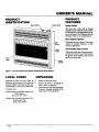
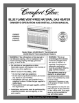
BLUE FLAME VENT-FREE NATURAL GAS HEATER
OWNER'S
OPERATION
AND INSTALLATION
MANUAL
i
CGN20TB
CGN20TLB
CGN30TB
CGN30TLB
i
/
/
Heater
Sizes: 20,000
Btu/Hr
30,000
Btu/Hr Thermostat
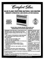
WARNING:
If the information
Thermostat
and
Model Heaters
in this manual is not I
followed exactly, a fire or explosion
causing property damage, personal
Lof ife.
may result
injury, or loss
m Do not store or use gasoline or other flammable
vapors and liquids in the vicinity of this or any
other appliance.
m WHAT TO DO IF YOU SMELL GAS
• Do not try to light any appliance.
• Do not touch any electrical switch; do not use any
phone in your building.
• Immediately call your gas supplier from a
neighbor's phone. Follow the gas supplier's
instructions.
• If you cannot reach your gas supplier, call the fire
department.
Installation and service must be performed by a
qualified installer, service agency, or the gas supplier.
]
WARNING: Improper installation, adjustment,
alteration, service, or maintenance can cause injury or
property damage. Refer to
this manual for correct installation
and operational
procedures. For assistance
or additional
information
consult a qualified installer,
service agency, or the gas
supplier.
WARNING:
This
is an
unvented gas-fired heater.
It uses air (oxygen) from the
room in which it is installed.
Provisions
for adequate
combustion
must be provided. Refer to page 4 of this
manual.
This appliance may be installed in an aftermarket* manufactured (mobile) home, where not prohibited
by state or local codes.
* Aftermarket: Completion of sale, notfor purposeofresale,fromthe manufacturer
This appliance is only for use with the type of gas indicated on the rating plate. This appliance is not
convertible for use with other gases.
BLUE
FLAME
NATURAL
SAFETY
INFORMATION
A
WARNINGS
HEATER
This appliance is only for use with the
type of gas indicated on the ratingplate.
This appliance is notconvertible for use
with other gases.
I,
2.
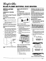
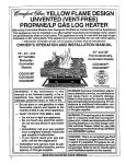
IMPORTANT: Read this owner's
manual carefully and completely
before trying to assemble, operate, or service thls heater. Improper use of this heater can
cause serlous Injuryor death from
bums, fire, explosion, elec_rlcal
shock, and carbon monoxlde
polsonlng.
GAS
.
If you smell gas
• shut off gas supply
• do not try to light any appliance
• do not touch any alectrical switch; do
not use any phone in your building
• immediately call your gas supplier
from a neighbor's phone. Follow the
gas supplier's instructions
• if you cannot reachyour gas supplier,
call the fu'e department
This heater shall not be installed in
a bedroom or bathroom.
4. Never install the heater
• in a recreational vehicle
_lb
poisoning
DANGER:
mayCarbon
lead to monoxide
death!
Carbon Monoxide Poisoning: Early
signs of carbon monoxide poisoning m=semblethe flu, with headaches,dizziness,
or nausea. If you have these signs, the heater
may not be working properly. Get fresh air
at once! Have beater serviced. Some people
are more affected by carbon monoxide than
others. These include pregnant women,
people with heart or lung disease or anemia,
those under the influence of alcohol, and
those at high altitudes.
Natural Gas: Natural gas is odorless. An
odor-making agent is added to natural gas.
The odor helps you detect a naturalgas leak.
However, the odor added to natural gas can
fade. Natural gas may be presenteven though
no odor exists.
Make certain you read and understand all
Warnings. Keep this manual for reference.
It is your guide to safe and proper operation
of this heater.
heater or its controls can be dan_WARNING:
Any change to this
gerous.
• where curtains, furniture, clothing, or
other flammable objects are less than
36 inches from the front, top, or sides
of the heater
• as a fireplace insert
• in high traffic areas
• in windy or drafty areas
5,
This heater needs fresh, outside air
ventilation to run properly. This heater
has an oxygen depletion sensor (ODS)
pilot light safety system. The ODS shuts
down the heater if not enough fresh air
is available. See Fresh Air for Combustion and Ventilatio_ pages 4 through 6.
6.
Keep air openings in front and bottom
of heater clear and free of debris. This
10. Surface of heater becomes
very hot
when running heater. Keep children and
adults away from hot surface to avoid
burns or clothing ignition. Heater will
remain hot for a time after shut-down.
Allow surface to cool before touching.
11. Carefully
supervise
young children
when they are in the same room with
heater.
12. Make sure grill guard is in place before running heater.
13. Do not use heater if any part has been
under water. Immediately call a qualified service technician to inspect the
room heater and to replace any part of
the control system and any gas control
which has been under water.
14. Turn off and unplug heater and let cool
before servicing. Only a qualified service person should service and repair
heater.
15. Operating heater above elevations of
4,500 feet could cause pilot outage.
will ensure enough air for proper combustion.
7.
8.
If heater shuts off, do not relight until
you provide fresh, outside air. If heater
keeps shutting off, have it serviced.
Do not run beater
• where flammable liquids or vapors
are used or stored
• under dusty conditions
9.
Never place any objects on the heater.
2
1o4&_ 7
OWNER'S
MANUAL
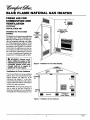
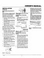
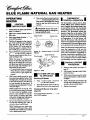
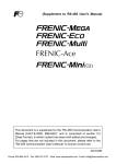
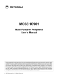
PRODUCT
FEATURES
PRODUCT
IDENTIFICATION
ControlKnob
IgnitorButton
Safety Device
This heater has a pilot with an Oxygen
Depletion Sensor Shutoff System (ODS).
The OI)S/pilot is arequired featurefar ventfree room heaters. The ODS/pilot shuts off
the heaterif there is not enough fresh air.
Plezo Ignition
Guard
Glass
Panel
Panel
Cabinet
Figure 1 - Vent-Free Natural Gas Heater (30,000 Btu/Hr Model Shown)
LOCAL
CODES
UNPACKING
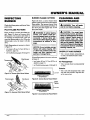
Install and use heater with care. Follow all
local codes. In the absence of loeal codes, use
the latest edition of the National Fuel Gas
1.
2.
CodeANSIZ223.1,aisoknownasNFPA54*.
*Available from:
3.
American National Standards Institute, Inc.
1430 Broadway
New York, NY 10018
Remove heater from carton.
Remove all protective packaging applied to heater for shipment.
Check heater for any shipping damage.
If heater is damaged, promptly inform
dealer where you bought heater.
National Fire Protection Association, Inc.
Batterymareh Park
Quincy, MA 02269
104331
3
System
This heaterhas a piezo igniWr.This system
requires no nlatehes, batteries, or other
sources to light heater.
Thermostatic
Heat Control
Thermostatmodels havea thermostatsensingbulb and a control valve. This results in
the greatest heater comfort. This can also
result in lower gas bills.
BLUE
FLAME
NATURAL
FRESH AIR FOR
COMBUSTION
AND
VENTILATION
_
WARNING: This heater shall
not be installed in a Confined
space unless provisions are provided for adequate combustion
and ventilation air. Read the following instructions to Insure
proper fresh air for this and other
fuel-burning
appliances In your
home.
Today's homes are built more energy efficient than ever. New materials, increased
insulation, and new construction methods
help reduce beat loss in homes. Home owners
weather strip and caulk around windows and
doors to keep the cold air out and the warm air
in. During heating months, home owners
want their homes as airtight as possible.
While it is good to make your home energy
efficient, your home needs to breathe. Fresh
air must enter your home. All fuel-burning
appliances need fresh air for proper combustion and ventilation.
Exhaust fans, fireplaces, clothes dryers, and
fuel burning appliances draw air from the
house to operate. You must provide adequate fresh air for these appliances. This
will insure proper venting of vented fuelburning appliances.
GAS
HEATER
PROVIDING ADEQUATE
VENTILATION
Confined
The following is exerpts from National Fuel
Gas Code. NFPA 54/ANSI Z223.1, Section
5.3, Air for Combustion and Ventilation.
1992 Section 5.3) defines a confined space
as a space whose volume is less than 50
cubic feet per 1,000 Btu per hour (4.8 m 3per
kw) of the aggregate input rating of all
appliances installed in that space and an
unconfined space as a space whose volume
is not less than 50 cubic feel per 1,000 Btu
per hour (4.8 m 3per kw) of the aggregate
input rating of all appliances installed in that
space. Rooms communicating directly with
the space in which the appliances are installed*, through opemngs not furnished
with doors, are considered a part of the
unconfined space.
Unusually Tight Contruction
Unconfined Space
3.
Confined Space
The information on pages 4 through 6 will
help you classify your space and provide
adequate ventilation.
Unusually Tlght Construction
The air that leaks around doors and windows may provide enough fresh air for
combustion and ventilation. However. in
buildings of unusually tight construction.
you must provide additional fresh air.
Unusually tight construction
fined as construction where:
a.
Sp_e
TheNationalFuelGasC-ode(ANSIZ223.1,
All spaces in homes fallinto one of the three
following ventilation classifications:
1.
2.
and Unconfined
is de-
This heater shall not be installed in a confined space or unusually tight construction
unless provisions are provided for adequate
combustion and ventilation air.
* Adjoining rooms are communicating only
if there aredoorless passageways or ventilation _511Sbetween them.
walls and ceilings exposed to the
outside atmosphere have a continuous water vapor retarder with
a rating of one perm (6 x 10 "11kg
per pe.seo.n_) or less with openings gasketed or sealedand
b. weather stripping
has been
added on openable windows and
doors and
c.
caulking or sealants are applied
to areas such as joints around
window and door frames, betwsen sole plates and floors, between wall-ceiling joints, between wall panels, at penetrations for plumbing, electrical, and
gas lines, and at other openings.
If your home meets all of the three
criteria above, you must provide additional fresh air. See Ventilation Air
From Outdoors, page 6.
If your home does not meet all of the
three criteria above, proceed to Determining Fresh-Air Flow For Heater
Location, page 5.
4
Io433!
OWNER'S
MANUAL
FRESH AIR FOR
COMBUSTION
AND
VENTILATION
Continued
DETERMINING
Determining
FRESH-AIR
FLOW
if You Have a Confined
FOR HEATER
or Unconfined
LOCATION
Space
Use this worksbeet to determine if you have a confined or unconfined space.
S pace: Includes the room in which you will install heater plus any adjoining rooms with doorless passageways or ventilation grilIsbetween
the rooms.
1.
Determine the volume of the space ('lengthx width x height).
l..¢ngth x Width x Height =
eu. ft. (volume of space)
Example: Space size 20 ft. (length) x 16 ft. (width) x 8 ft. (ceiling height) = 2560 eu. ft. (volt_ee of space)
If additional ventilation to adjoining room is supplied with grills or openings, add the vohmm of these rooms to the total volume of
the space.
2.
Divide the space volume by 50 cubic feet to determine the maximum Btu/Hr the space can support.
3.
Example: 2560 cu. ft. (volume of space) + 50 cu. ft. = 51.2 or 51,200 (maximum Btu/Hr the spac_ can support)
Add the Btu/Hr of all fuel burning appliances in the space.
Vent-free heater
Btu/Hr
(volume of space) + 50 cu. ft. = (Maximum Btu/Hr the space can support)
Gas water heater*
Btu/Hr
Example:
Gas furnace
Btu/Hr
Gas water heater
Vented gas heater
Btu/Hr
Vent-free heater
Gas fireplace logs
Other gas appliances*
Total
Btu/l-Ir
Btu/Hr
Btu/Hr
Total
+
=
40,000
Btu/Hr
+
20,000
Btu/Hr
=
60,000
Btu/I-lr
* Do not include direct-vent gas appliances. Direct-vent draws combustion air from the outdoors and vents to the outdoors.
4.
Compare the maximum Btu/Hr the space can support with the actual amount of Btu/Hr used.
Btu/Hr (maximum the space can support)
Btu/l-Ir (actual amount of Btu/Hr used)
Example:
51,200 Btu/Hr (maximum the space can support)
60,000 Btu/Hr (actual amount of Btu/Hr used)
The space in the above example is a confined space because the actual Btu/Hr used is more than the maximum Btu/Hr the space can support.
You must provide additional fresh air. Your options are as follows:
A.
Rework worksheet, adding the space of an adjoining room. If the extra space provides an unconfined space, remove door to adjoining room or add ventilation grills between rooms. See Ventilation Air From Inside Building, page 6.
B.
C.
Vent room directly to the outdoors. See Ventilation Air From Outdoors, page 6.
Install a lower Btu/Hr heater, if lower Btu/Hr size makes room unconfined.
If the actual Btu/Hr used is less than the maximum Btu/I-Ir the space can support, the space is an unconfined space. You will need no
additional fresh air ventilation.
WARNING: If the area in which the heater may be operated is smaller than that defined as an unconfined space,
provide adequate combustion and ventilation air by one of the methods described in the National FuelGas Code,
ANSI Z223.1, 1992, Section 5.3 or applicable local codes.
Continued
I04_I
5
BLUE
FLAME
NATURAL
GAS
HEATER
FRESH AIR FOR
COMBUSTION
AND
VENTILATION
Continued
VENTILATION
AIR
Ventilation Air From Inside
Building
This fresh air would come from anadjoining
unconfined space. When ventilating to an
adjoining unconfined space, you must provide two permanent openings: one within
12" of the ceiling and one within 12" of the
floor on the wall connecting the two spaces
(see options 1and 2, Figure 2). You can also
remove door into adjoining room (see option 3, Figure 2). Follow the National Fuel
Gas Code NFPA 54/ANSI Z223.1, Section
5.3, Air for Combastion and Ventilation for
required size of ventilation grills or ducts.
,_ WARNING: Rework worksheet, adding the space of the
adjoining unconfined space. The
combined spaces must have
enough fresh air to supply all
appliances in both spaces.
Ventilation
Ventilation Gdlls
Into/_olnlng Room,:
Option 2
Vent,atlon
Gdlls
into Adjoining
Room,
Option
Figure 2 - Ventilation Air from Inside Building
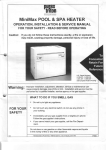
Air From Outdoors
Provide extra fresh air by using ventilation
grills or ducts. You must provide two permanent openings: one within 12" of the
ceiling and one within 12" of the floor.
Connect these items directly to the outdoors
or spaces open to the outdoors. These spaces
include attics and crawl spaces.
IMPORTANT: Do not provideopenings for
inlet or outlet air into attic if attic has a
thermostat-controUed power vent. Heated air
entering the attic will activate the power vent.
Outlet
Air
To Attic
...............
tHI6H....P
_]
Inlel
Air
To
Crawl
Space
IIIIIIIIIIIIIIII
Inlet Air
Ventilated
Crawl Space
Figure 3 - Ventilation Air from Outdoors
6
104331
OWNER'S
INSTALLATION
NOTICE: This heater is intended
for use as supplemental heat. Use
this heater along with your primary heating system. Do not install this heater as your primary
heat source. If you have a central
heating system, you may run
system's circulating blowerwhne
using heater. This will help circulate the heat throughout
the
house. In the event of a power
outage, you can use this heater
as your primary heat source.
NOTICE: A qualified service person must install heater. Follow
all local codes.
CHECK GAS TYPE
Use only natural gas. If your gas supply is
not natural gas, do not install heater. Call
dealer where you bought heater for proper
type heater.
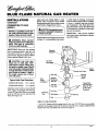
INSTALLATION
HEATER
This heater is designed to be mounted on a
wall.
_k WARNING: Maintain the minimum clearances shown In Figure
4. ffyou can, provide greater clearances from floor, ceiling, and joining wall.
You can locate heater on floor, away from a
wall. An optional floor mounting stand is
needed. Purchase the floor mounting stand
from your dealer. See Accessories, page 18.
WARNING: Never install the
heater
• in a bedroom or a bathroom
• in a recreational vehicle
• where curtains,
furniture,
clothing, or other flammable
objects are less than 36 inches
from the front, top, or sides of
the heater
• as a fireplace insert
• in high traffic areas
• in windy or drafty areas
CAUTION: If you Install the
heater in a home garage
• heater pilot and burner must
be at least 18 inches above
floor
• Iocete heater where moving vehicle will not hit it
For conveniance andefficiency, install heater
• where there is easy access for operation,
inspection, and service
• in coldest part of room
An optional fan kit is available from your
dealer. See Accessories, page 18. If planning to use fan, locate heater near an electrical outlet.
ITEMS
Before installing heater, make sure you have
the items listed below.
• piping (check local cedes)
• sealant (resistant to propane/LP gas)
• manual shutoff valve *
• ground joint union
• test gauge connection * (see Figure 13,
page 10)
• sediment trap
• tee joint
• pipe wrench
•
LOCATING
MANUAL
test gauge connection*
* An A.G.A. design-certified manual shutoff
valve with 1/8" NPT tap is an acceptable
alternative to test gauge connection. Purchase the optional A.G.A. design-certified
manual shutoff valve from your dealer. See
Accessories,
page 18.
CAUTION: This heater creates warm air currents. These
currents move heat to wall surfaces next to heater. Installing
heater next to vinyl or cloth wall
coverings or operating heater
where Impurities (such as tobacco smoke, aromatic candles,
cleaning fluids, oil or kerosene
lamps, etc.) In the air exist, may
discolor walls.
Minimum
to Top
FLOOa
Sudace
of Carpeting or
Other Combustible
Material
="
Figure4 - MountlngClearancesAs Viewed
From Front of Heater
IMPORTANT: Vent-free heaters add motstare to the air. Although this is beneficial,
installing heater in rooms without enough
ventilation air may cause mildew to form from
too much moisture. See Fresh Air for Combustion and Ventilation, pages 4 through6.
Comin_d
104331
7
BLUE
FLAME
NATURAL
INSTALLATION
INSTALUNG
WALL
Continued
THERMOSTAT
BULB
SENSING
The thermostat sensing bulb has been
placed inside the heater for protection
during shipping.
Mounting
GAS
HEATER
HEATER TO
Bracket
The mounting bracket is located on back
panel of heater. It has been taped there for
shipping. Remove mounting bracket from
back panel.
Remove front panel of heater (see Figure 7).
2.
Locate thermostat sensing bulb just
under burner assembly.
IMPORTANT: Attach thermostat sensing
bulb to back of heater for proper operation.
Attaching
Bulb
1.
2.
3.
Thermostat
Sensing
Remove thermostat sensing bulb from
holders inside heater. Route through
slot opening in bottom of heater.
Place clamp on thermostat sensing bulb
as shown in Figure 5. Clamp is provided in hardware package.
Snap clamp into upper mounting hole
as shown in Figure 5. Mounting hole is
located on lower left edge on back of
heater. Make sure the thermostat sensis pointing
Attaching to wall anchor: Thismethod
allows you to attach mounting bracket to
hollow walls (wall areas between studs) or
to solid walls (concrete or masonry).
Decide which method better suits your needs.
Either method will provide a secure hold for
the mounting brackeL
Locating Thermostat Sensing
Bulb
1.
Attaching to wall stud:This method
provides the strongest hold. Insert mounting
screws through mounting bracket and into
wall studs.
Marking
1.
Screw Locations
Tape mounting bracket to wall where
heater will be located. Make sure
mounting bracket is level.
Figure 6 - Bracket Location
_kWARNING:
Removing Front Panel Of Heater
1. Remove two screws near bottom corners of front panel.
2.
Lit_ straight up on gfiUguard until it stops.
Grill guard will slide up about 1/4",
3.
Pull bottom of front panel forward, then
downward.
4.
Remove cardboard packing from grill
and glass.
clearances shown in Figure 8. If
you can, provide greater clearancas from floor and joining wall.
2.
Mark screw locations on wall (see Figure 8).
Note: Only mark last hole on each end
of mounting bracket. Insert mounting
screws through these holes only.
3.
up.
Maintain minimum
Remove tape and mounting bracket
from wall.
\
Thermostat
Figure 7- Removing Front Panel Of Heater
Figure 5- Attaching Thermostat Sensing
Bulb
/I
Only Insert MoLmtlng
Screws Through Last
Hole On Each End
18 3/4"
MI_.
30,000 Btu/Hr Model
Methods For Attaching
Mounting
Bracket To Wall
Only use last hole on each end of mounting
bracket to attach bracket to wall. These two
holes are 16 inches apart from their centers.
Attach mounting bracket to wall in one of
two ways.
1. Attaching to wall stud
2.
Screws Through
Last
18 3/4"
MIn.
Attaching to wall anchor
20,000 Btu/Hr Models
Figure 8 - Mounting Bracket Clearances
8
104331
OWNER'S
INSTALLATION
7.
Hold spacer in place with one hand.
With other hand, insert mounting screw
through bottom mounting hole and
spacer. Place tip of screw in opening
of wall anchor or drilled bole.
8.
Tighten both screws until heater is
firmly secured to wall. Do not over
tighten.
Continued
Attaching
Wail
Mounting
Bracket To
Note: Wall anchors, mounting screws, and
spacers are in hardware package. The hardware package is provided with heater.
Figure 10 - Popping Open Anchor Wings
For Thin Walls
Attaching to wall stud method
Placing Heater On Mounting
Bracket
For attachingmounting bracketto wall studs.
1.
Locate two horizontal slots on back
panel of heater.
2.
Place heater onto mounting bracket.
Slide horizontal slots onto stand-out
tabs on mounting bracket.
1.
Drill holes at marked locations using
9/64" drill bit.
2.
Place mounting bracket onto wall. Line
up last hole on each end of bracketwith
holes drilled in wall.
3.
Insertmounting screws through bracket
and into wall studs.
4.
Tighten screws until mounting bracket
is fli'mly fastened to wall studs.
Attaching to wall anchor method
Stand-Out Tab
Figure 12 - Installing Bottom Mounting
Screws
Mounting Bracket
(attached to wail)
I.
Drill holes at marked locations using
5/16" drill bit. For solid walls (concrete
or masonry), drill at least 1" deep.
Figure 11 - Mounting
Mounting Bracket
2.
Fold wall anchor
3.
Insert wall anchor (wings first) into
hole. Tap anchor flush to wall.
Installing Bottom Mounting
Screws
4.
For thin walls (1/2" or less), insert red
key into wall anchor. Push red key to
"pop" open anchor wings.
IMPORTANT." Do not hammer key!
For thick walls (over 1/2" thick) or solid
walls, do not pop open wings.
5.
Place mounting bracket onto wall. Line
up last hole on each end of bracket with
wall anchors.
6.
Insert mounting screws through bracket
and into wall anchors.
7.
Tighten screws until mounting
is firmly fastened to wall.
bracket
1.
Heater
Onto
2.
Locate two bottom mounting
holes.
These holes are near bottom on back
panel of heater (see Figure 12).
Mark screw locations on wall.
3.
Remove heater from mounting bracket.
4.
If installing bottom mounting screws
into hollow or solid wall, install wall
anchors. Follow steps 1 through 4 under Attaching To Wall Anchor Method.
If installing bottom mounting screw
into wal! stud, drill holes at marked locations using 9/64" drill bit.
5.
Replace heater onto mounting
6.
Place spacers between bottom mounting holes and wall anchor or drilled hole.
Figure 9 - Folding Anchor
104337
Nolo: Do not replace front panel at this
time. Replace front panel after making
gas connections and checking for leaks
(see pages 10 and ll). Make gas connections and check for leaks before replacing front panel (see pages 10 and 11).
_
For attaching mounting bracket to hollow
walls (wall areas between studs) or solid
walls (concrete or masonry).
as shown in Figure 9.
:MANUAL
9
bracket.
BLUE
FLAME
INATURAL
INSTALLATION
Continued
CONNECTING
SUPPLY
TO GAS
NOTICE: A qualified service person must connect heater to gas
supply. Follow all local codes.
WARNING: Never connect
heater to private (non-utility) gas
wells. This gas is commonly
known as well-head gas.
GAS
_CAUTION:
Useplpejoint sealant that Is resistant to liquid petroleum (LP) gas.
20,000 Btu/Hr Models
30,000 Btu/Hr Models
3/8" or greater
Pressure
Regulator
3/8" NPT
Heater
Cabinet
r Tee Joint
,,_'_
/
Test
Gau e
_
/
Reducer
Bushingto
_
\\
_
L
\ Sh.to.
_
[
L_
1/8"NPT/
PlugTap
_
J
_
T ,°l
Inle,
_/
j,,,,,,,.---,_,=r
_
Sediment r. Tee Joint_
Trap
_
Pipe Nipple
L cap
Manual
Valve *
con ooion
1/8".ST I
1/2" or greater
Installation must include a manual shutoff
valve, union, and plugged 1/8" NPT tap.
Locate NPT tap within reach for test gauge
hook up. NPT tap must be upstream from
heater (see Figure 13).
IMPORTANT:
Hold pressure regulator
with wrench when connecting it to gas piping and/or fittings.
Install sediment trapin supply line as shown
in Figure 13. Locate sediment hap where it
CAUTION: Use only new,
black iron or steel pipe. Internally-tinned copper tubing may
be used in certain areas. Check
your local codes. Use pipe of large
enough diameter to allow proper
gas volume to heater. If pipe is
too small, undue loss of pressure will occur.
Inlet Pipe Diameters
is within reach for cleaning. Locate b_diment trapwhere trappedmatte_is not likely
to freeze. A sediment trap traps moisture
and contaminants. This keeps them from
going into heater controls. If sediment trap
is not installed or is installed wrong, heater
may not run properly.
Apply pipe joint sealant lightly to male
threads. This will prevent excess sealant
from going in_ pipe. Excess sealant in pipe
could result in clogged heater valves.
IMPORTANT: Check gas line pressure
before connecting heater to gas line. Gas
line pressure must be no greater than 14
inches of water. If gas line pressure is higher.
heater regulator damage could occur.
Typical
HEATER
Pipefrom Gas
Meter (5"W.C.
to 10.5"W.C.
Pressure)
LIa,, imum
_]'_---_----
Figure 13 - Gas Connection
• An A.G.A. design-certified manual shutoff valve with 1/8" NI_ tap is an acceptable
alternative to test gauge connection. Purchase the optional A.G.A. design-certified manual
shuU3ffvalve from your dealer. See Accessories, page 18.
t0
I0433_
OWNER'S
INSTALLATION
Continued
CHECKING GAS
CONNECTIONS
WARNING: Test all gas pipIng and connections for leaks
after Installatlon or servicing.
Correct all leaks at once.
_WARNING:
Never usean open
flame to check for a leak. Apply a
mlxture of liquid soap and water
to all joints. Bubbles forming
show a leak. Correct all leaks at
Pressure Testing Heater Gas
Connections
1,
Open manual shutoff valve (see Figure 14).
2.
Open main gas valve located on or near
gas meter.
Make sure control knob of heater is in
the OFF position.
3.
4.
5.
6.
once.
Pressure Testing
Piping System
2.
3.
4.
5.
Cap off open end of gas pipe where
manual shutoff valve was connected.
Pressurize supply piping system by either using compressed air or opening
main gas valve located on or near gas
meter.
Light heater (see Operating Heater).
Check the rest of the internal joints for
leaks.
7.
Turn off heater (see To Turn Off Gas to
Appliance, page 12).
8.
Replace
Gas Supply
Test Pressures In Excess Of 1/2 PSIG
1,
Disconnect heater and its individual
manual shutoff valve from gas supply
piping system. Pressures in excess of
1/2 psig will damage heater regulator.
Check all joints from manual shutoff
valve to thermostat gas valve (see Figure 15). Apply mixture of liquid soap
and water to gas joints. Bubbles forming show a leak.
Correct all leaks at once.
Manual
Shutoff
OPERATING
HEATER
I
Valve __?__
A.
B.
Figure 14 - Manual Shutoff Valve
Thermostat Gas Valve
2.
Pressurize supply piping system by either using compressed air or opening
main gas valve located on or near gas
meter.
3.
Check all joints from gas meter to
manual shutoff valve (see Figure 15).
Apply mixture of liquid soap and water to gas joints. Bubbles forming show
a leak.
4.
Correct
IF YOU
SMELL
C.
Use only your hand to push in or turn
the gas control knob. Never use tools.
If the knob will not push in or turn
by hand, don't try to repair it, call u
qualified service technician or gas
supplier. Force or attempted repair
may result in a fire or explosion.
D.
Do not use this appliance if any part
has been under water. Immediately
call a qualified service technician to
inspect the appliance and to replace
any part of the control system and
any gas control which has been under water.
Check all joints of gas supply piping
system. Apply mixture of liquid soap
and water to gas joints. Bubbles forming show a leak.
Correct all leaks at once.
Close manual shutoff valve (see Figure 14).
TO DO
• Do not try to light any appliance.
• Do not touch any dectric switch; do
not use any phone in your buildinl_
• Immediately call your gas supplier
from a neighbor's
phone. Follow
the gas supplier's instructions.
• If you cannot reach your gas supplier, call the fire department.
Closed
Test Pressures Equal To or Less Than
1/2 PSIG
I
This appliance has a pilot which must
be lighted by hand When lighting the
pilot, follow these instructions exactly.
BEFORE LIGHTING smell all
around the appliance area for ga_ Be
sure to smell next to the floor because
some gas is heavier than air and will
settle on the floor.
WHAT
GAS
on
,
_J
READ BEFORE
FOR YOUR SAFETY
LIGHTING
WARNING: If you do not follow these Instructions exactly, a
fire or explosion may result causIng property damage, personal
injury or loss of life.
front panel.
r_[_-_OP
J
II t
//F_
_
\
MANUAL
all leaks at once.
Continued
i_331
11
BLUE
FLAME
NATURAL
8.
OPERATING
HEATER
LIGHTING
INSTRUCTIONS
1.
2.
/
STOP! Read the safety information,
page 11, column 3.
Make sure manual shutoff valve is
fully open.
3.
Turn control knob clockwise
to the OFF position.
4.
Wait five (5) minutes to dear out any
gas. Then smell for gas, including
near the floor. If you smell gas,
STOP! Follow "B" in the safety information, page 11, column 3. If you
don't smell gas, go to the next step.
Turn control knob counterclockwise
5.
to the PILOT
position.
Press in control knob for five (5) secands (see Figure 16).
Note:
heater
You may be running
this
for the first time after hook-
GAS
HEATER
Turn control knob counterclockwise
to desired heating level. The
main burner should light. Set control
knob to any heat level between HI
and LO.
just heating levels by using the
_k CAUTION:
not try to admanual
shutoff Do
valve.
I
Ignitor Button
Control Knob
Figure 16 - Control Knob In The OFF
Position
Therm°c°_Pl_//_
Or Elo_irl°_Bumer
ing up to gas supply. If so, the control knob may need to be pressed in
for 30 seconds. This will allow air to
bleed from the gas system.
• If control knob does not pop up
when released, contact a qualified
service person or gas supplier for
repairs.
6.
With control knob pressed in, push
down and release ignitor button. This
will light pilot. The pilot is attached
to the front of burner. The pilot can
be seen through the glass panel. If
needed, keep pressing ignitor button
until pilot lights.
Note: If pilot does not stay lit, refer
to Troubleshooting,
pages 14 through
16. Also contact a qualified service
person or gas supplier for repairs.
Until repairs
are made, light pilot
with match. To light pilot with match,
see Manual Lighting Procedure.
7.
I
Note: The thermostat sensing bulb measures the temperature
of air near the
heater cabinet. This may not always agree
with room temperature
(depending
on
housing construction,
installation
location, room size, open air temperatures,
etc.). Frequent use of your heater will let
you determine your own comfort levels.
MANUAL
LIGHTING
PROCEDURE
I
1.
Remove front panel (see Figure 7,
page 8).
2.
Follow steps 1 through 5 under Lighting Instructions.
With control knob pressed in, strike
match. Hold match to pilot until pilot lights.
TOTURN
OFF GAS
TO APPLIANCE
Shutting
Off Heater
1.
Turn
control
2.
to the OFF position.
Turn off all electric power to the appliance if service is to be performed.
knob
1
The thermostatic control used on these
models differs from standard thermostats. Standard thermostats simply turn
on and off the burner. The thermostat
used on this heater senses the room ternperature. The thermostat
adjusts the
amount of gas flow to the burner. This
increases or decreases the burner flame
height. At times the room may exceed the
set temperature. If so, the burner will
shut off. The burner will cycle back on
when room temperature drops below the
set temperature. The control knob can be
set to any heat level between HI and LO.
I
Figure 17- Pilot
THERMOSTAT
CONTROL
OPERATION
clockwise
4.
Keep control knob pressed in for 30
seconds after lighting pilot. After 30
seconds, release control knob.
5.
Replace front panel.
Shutting Off Burner Only (pilot
stays lit)
Turn control knob clockwise
the PILOT position.
_
to
Keep control knob pressed in for 30
seconds after lighting pilot. After 30
seconds, release control knob.
Note: If pilot goes out, repeat steps
3 through 7. This heater has a safety
interlock system. Wait one (1) minute
before lighting pilot again.
12
104331
OWNER'S
BURNER
INSPECTING
BURNER
Check pilot flame pattern and burner flame
pattern often.
PILOT FLAME
PATTERN
Figure 18 shows a correct pilot flame paturn. Figure 19 shows an incorrect pilot
flame pattern. The incorrect pilot flame is
not touching the thermocouple. This will
cause the thermocouple to cool. When the
thermocouple cools, the heater will shut
down.
If pilot flame pattern
in Figure 19.
is incorrect,
FLAME PATrERN
Figure 20 shows a correct burner flame
pattern. Figure 21 shows an incorrect burner
flame pattern. The incorrect burner flame
pattern shows yellow tipping of the flame. It
also shows the flame higher than 1/2 the
glass panel height.
WARNING: If yellow tipping
occurs, your heater could produce increased levels of carbon
monoxide. If burner flame pattern shows yellow tipping, follow
instructions at bottom of this
page.
as shown
•
turn heater off (see To Turn OffGas
Appliance, page 12).
•
seeTroubleshooting,
to
pagesl4throughl6.
Pilot Burner
NOTICE: Do not mistake orange
flames with yellow tipping. Dirt
or other fine particles enter the
heater and burn causing brief
patches of orange flame.
CAUTION: You must keep
control areas, burner, and circulating air passageways of heater
clean. Inspect these areas of
heater before each use. Have
heater inspected yearly by a qualb
fled service person.Heater may
need more frequent cleaning due
to excessive lint from carpeting,
bedding material, etc.
ODS/PILOT
AND BURNER
• Use a vacuum cleaner, pressurized air,
or small, soft bristled brush to clean.
• turn heater off(see To Turn OffGas to
Appliance, page 12).
Air Passageways
• Use a vacuum cleaner or pressurized air
to clean.
• Use a soft cloth dampened with a mild
_,,.=,,_ Exterior
soap and water mixture. Wipe the cabinet to remove dust.
CORRECT FLAME PATTERN
AT HIGH POSITION
Figure 20- Correct Burner Flame Pattern
Yellow
INCORRECT FLAME PAI"rERN
AT HIGH POSmON
Figure 19 - Incorrect Pilot Flame Pattern
Figure 21 - Incorrect Burner Flame Pattern
lo,_331
• 1=WARNING: Tum off heater
and let cool before cleaning.
CABINET
Figure 18- Correct Pilot Flame Pattern
Pilot Burner
CLEANING
AND
MAINTENANCE
If burner flame pattern is incorrect, as shown
in Figure 21
• seeTroubleshooting, pages 14through 16.
Thermocouple
MANUAL
13
BLUE
FLAME
NATURAL
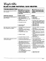
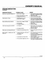
TROUBLESHOOTING
Noto:AIl troubleshooting items arelisted in
order of operation.
OBSERVED
PROBLEM
When ignitor button is pressed, there is no
spark at ODS/pilot
_,
GAS
HEATER
WARNING: Turn off and un-
plug heater and let cool before
serv|clng. Only a qualified service person should servlca and
repair heater.
POSSIBLE
CAUSE
1. Ignitor electrode positioned wrong
2. Ignitor electrode broken
3. Ignitor electrode not connected to ignitor cable
4. Ignitor cable pinched or wet
5. Piezo ignitor nut is loose
6. Broken ignitor cable
7. Bad piezo ignitor
When ignitor button is pressed, there is
spark at ODS/pilot but no ignition
1. Gas supply turned offor manual shutoff
valve closed
2. Control knob not in PILOT position
3. Control knob not pressed in while in
PILOT position
4. Air in gas lines when installed
5. ODS/pilot is clogged
6. Gas regulator setting is not correct
ODS/pilot lights but flame goes out when
control knob is released
1. Control knob not fully pressed in
2. Control knob not pressed in long enough
3. Safety interlock system has been triggered Cl'hermostat models only)
4. Manual shutoff valve not fully open
5. Thermocouple connection loose at control valve
6. Pilot flame not touching thermocouple,
which allows thermocouple to cool,
causing pilot flame to go out. This problem could he caused by one or both of
the following:
A) Low gas pressure
B) Dirty or partially clogged ODS/pilot
7. Thermocouple damaged
8. Control valve damaged
14
A CAUTION: Never use s wire, I
needle, or similar object to clean
ODS/pllot.This can damage ODS/
pilot unit.
I
REMEDY
1. Replace ignitor
2. Replace ignitor
3. Reconnect ignitor cable
4. Free ignitor cable if pinched by any
metal or tubing. Keep ignitor cable dry
5. Tighten nut holding piezo ignitor to
heater cabinet. Nut is located inside
heater cabinet at top
6. Replace ignitor cable
7. Replace piezo ignitor
1. Turn on gas supply or open manual
shutoff valve
2. Turn control knob to PILOT position
3. Press in control knob while in PILOT
position
4. Continue holding down control knob.
Repeat igniting operation until air is
removed
5. Clean ODS/pilot (see Cleaning and
Maintenance, page 13) or replace ODS/
pilot assembly
6. Replace gas regulator
1. Press in control knob fully
2. After ODS/pilot lights, keep control
knob pressed in 30 seconds
3. Wait one (1) minute for safety interlock
system to reset. Repeat ignition operation
4. Fully open manual shut-offvalve
5. Hand tighten until snug, then tighten 1/4
turn more
6. A) Contact local natural gas company
B) Clean ODS/pilot (see Cleaning and
Maintenance, page 13) or replace ODS/
pilot assembly
7. Replace
8. Replace
thermocouple
control valve
to_331
OWNER'S
MANUAL
TROUBLESHOOTING
Continued
OBSERVED
PROBLEM
Burner does not light after ODS/pilot is lit
POSSIBLE
CAUSE
I. Burner orifice is clogged
2. Burner orifice diameter is too small
3. Inlet gas pressure is too low
REMEDY
1. Clean burner (see Cleaning and Maintenance, page 13) or replace burner orifice
2. Replacebumerorifiee
3. Contact local natural gas company
Delayed ignition of burner
1. Manifold pressure is too low
2. Burner orifice is clogged
1. Contact local natural gas company
2. Clean burner(see Cleaning and Maintenance, page 13) or replace burner orifice
Burner backfiring during combustion
1. Burner orifice is clogged or damaged
1. Clean burner (see Cleaning and Maintenance, page 13) or replace burner orifice
2. Replace burner
3. Replace gas regulator
2. Burner damaged
3. Gas regulator defective
Yellow flame during burner combustion
1. Not enough air
2. Gas regulator defective
1. Check burner for dirt and debris. If
found, clean burner (see Cleaning and
Maintenance, page 13)
2. Replace gas regulator
Slighismokeorodorduringinitialoperation
1. Residues frommanufacturing processes
1. Problem will stop after a few hours of
operation
Heater produces a whistling noise when
burner is lit
1. Turning control knob to HI position
when burner is cold
2. Air in gas line
1. Turn control knob to LO position and
let warm up for a minute
2. Operate burner until air is removed from
line. Have gas line checked by local
natural gas company
3. Observe minimum installation clearances (see Figure 4, page 7)
4. Clean burner(see Cleaning andMaintenance, page 13) or replace burner orifice
3. Air passageways on heater blocked
4. Dirty or partially clogged burner orifice
Continued
Io433T
15
BLUE
FLAME
NATURAL
GAS
HEATER
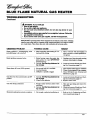
TROUBLESHOOTING
Continued
A WARNING: If you smell gas
• Shut off gas supply.
• Do not try to light any appliance.
• Do not touch any electrical switch; do not use any phone in your
building.
• Immediately call your gas supplier from a neighbor's phone. Fonowthe
gas suppller's instructions.
• If you cannot reach your gas supplier, call the fire department.
IMPORTANT: Operatingheaterwhere impurities in air exist may createodors.Cleaning
supplies,paint,paintremover, cigarettesmoke, cementsand glues,new carpetor textiles,
etc., create fumes. These fumes may mix with combustion air and create odors.
OBSERVED
PROBLEM
POSSIBLE
CAUSE
REMEDY
Heater produces a clicking/ticking noise
just after burner is lit or shut off
1. Metal expanding while heating or contracting while cooling
1. This is common with most heaters. If
noise is excessive, contact qualified service person
Heater
1. Heater
|.
produces
unwanted
odors
burning
vapors
from
paint,
hair
spray, glues, etc. (see IMPORTANT
statement above)
2. Gas leak. See Warning statement
at
top of page
Ventilate
room.
Stop using
odor
causing
products while heater is running
2. Locate and correct all leaks (see Checking Gas Connections, page 11)
Heatershutsoffinuse(ODSoperates)
1. Not enough fresh air is available
2. Low line pressure
3. ODS/pilot is partially clogged
1. Open window and/or door for ventilation
2. Contact local propaneJLP gas company
3. Clean ODS/pilot (see Cleaning and
Maintenance, page 13)
Gas odor even when control knob is in OFF
position
1. Gas leak. See Warning statement
top of page
2. Control valve defective
at
1. Locate and correct all leaks (see Checking Gas Connections, page 11)
2. Replace control valve
Gas odor during combustion
1. Foreign matter between control valve
and burner
2. Gasleak.SeeWerningstatementat
top of page
1. Take apart gas tubing and remove foreign matter
2. Locate and correct all leaks (see Checking Gas Connections, page 11)
Moisture/condensation noticed on windows
1. Not enough combustion/ventilation air
1. Refer to Air for Combustion and Ventilation requirements (page 4)
OWNER'S
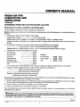
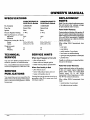
SPECIFICATIONS
CGN20TB/CGN20TLB
20,000 Btu/Hr Models
CGN30TB/CGN30TLB
30,000 Btu/Hr Models
Btu (Variable)
10,000/20,000
15,000/30,000
Type Gas
Natural Only
Ignition
Piezo
Natural Only
Piezo
Pressure Regulator Setting
3"W.C.
3" W.C.
Inlet Gas Pressure (in. of water)
Maximum
10.5"
Minimum
5"
5"
Dimensions,
Heater
Carton
23.5x25.9x8.025.8x28.7x10.1
Weight (pounds)
Heater
Shipping
22
27
REPLACEMENT
PARTS
Note: Use only original replacement parts.
This will protect your warranty coverage
for parts replaced under warranty.
Parts Under Warranty
10.5"
Inches (H x W x D)
23.5 x 18.5 x 8.0
25.8 x21.3 x I0.I
MANUAL
....
Contactauthorizeddealers of this product If
they can't supplyoriginal replacement part(s),
eithercontactyour nearestPartsCentral (page
19) or call DESA International's Technical
Service Department at 1-800-323-5190 for
re_ferral_inform_atio
n.......
When calling DESA International,
ready
your
30
35
have
nalne
your address
model number of your heater
TECHNICAL
SERVICE
SERVICE
When Gas Pressure
• pilot will not stay lit
If so, contact DESA International's Technical Service Department at 1-800-323-5190.
• heater will not produce specified heat
You can purchase a service manual from the
address listed on the back page of this manual.
Send a check for $5.00 payable to DESA
International.
Io4331
• burner will have delayed ignition
When Gas Quality
Is Bad
• pilot will not stay lit
• burner will produce flames and soot
• heater will backfire when lit
You may feel your gas pressure is too low or
gas quality is bad. If so, contact your local
natural gas supplier.
17
type of gas used (lxopa_/LP or natural gas)
purchase date
Is Too Low
You may have further questions about installation, operation, or troubleshooting.
SERVICE
PUBLICATIONS
how heater was malfunctioning
HINTS
Usually, we will ask you to return the defective part to the factory.
Parts Not Under Warranty
Contact authorized dealers of this product.
If they can't supply original replacement
part(s), either contact your nearest Parts
Central
(page 19) or call DESA
International's Parts Department at 1-800972-7879 for referral information.
When
ready:
calling
DESA
International,
•
model number of your heater
•
the replacement
part number
have
BLUE
FLAME
NATURAL
GAS
HEATER
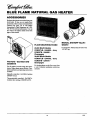
ACCESSORIES
Purchase these heater accessories from your
local dealer. If they can not supply these
accessories, eithercontact your nearest Parts
Central (see page 19) or call DESA
International's Parts Department at 1-800972-7879 for referral information. You can
also write to the address listed on the back
page of this manual.
FLOOR MOUNTING
STAND
20,000 Btu/Hr Models
CGN20TLB - GA4500L
CGN20TB - GA4500 -
- Ivory
MANUAL
GA5010
SHUTOFF
VALVE -
For all models. Manual shutoff valve with
1/8" NFI" tap.
Champagne
30,000 Btu/l-lr Models
FAN KITS - GA3100A AND
GA3200TA
For all models. Provides batter heat distribution. Makes heater more efficient. Colnplete installation and operating instructions
included.
CGN30TLB - GA4510L
CGN30TB - GA4510 -
- Ivory
Champagne
For locating heater on the floor, away from
a wall. Complete installation instructions
included.
Manuallycontrolled
-GA3100A. Includes
ONIOFF switch.
Thermostatically controlled - GA3200TA.
Includes three settings: ON/OFF/AUTO.
18
_o,_
OWNER'S
MANUAL
PARTS CENTRALS
These Parts Centrals are privately owned businesses. They have agreed to support Our
customer's needs by providing original replacement parts and accessories.
':
Baltimore Electric
Dayton
1348 Dixwell Avenue
Master Service Center
1184 Wilson NW
Hamden, CT 06514
1-800-397-7553
203-248-7553
Walker, M149504
616-791-4760
1-800-446-1446
North Dayton Station
Dayton, OH 45404
All States
Parts Department
Washer Equipment
1715 Main Street
Portable
Heater Parts
342 N. County Rd. 400 East
Valparaiso,IN 46383
All States
219-462-7441
1-800-362-6951
FBD
P.O. Box 1096
1720 Kummer Road
Franklin, KY 42134
502-586-1922
1-800-654-8534
Four Flags Power Products
1115 Stateline Road
Niles, MI 49120
616-684-2697
1-800-268-4983
w4331
Co.
Kansas City, MO 64108
KS, MO, AR
816-842-3911
East Coast Energy Products
833 Broadway
W. Long Branch, NJ 07764
908-870-8809
1-800-755-8809
Tarantin
Tank Co.
P.O. Box 6129
Freehold, NJ 07728
908-780-9340
1-800-922-0724
Hardware
P.O. Box 275
513-258-3721
OH 1-800-762-3426
Halco Enterprises
208 Carter Drive, Unit 21
WesI Chester, PA I93_2215-696-2670
1-800-368-0803
LA Porte's Parts & Service
2444 N. 5th Street
HartsviUe, SC 29550
803-332-0191
Parts Department
Cans Unlimited,
P.O. Box 645
Albany Ladder
1586.90 Central Avenue
Albany, NY 12205
NY, MA, VT
518-869-5335
1-800-354-7368
19
Taylor, SC 29687
All States
803-879-3009
1-800-845-5301
Inc.
BLUE
FLAME
NATURAL
GAS HEATER
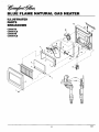
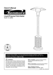
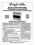
ILLUSTRATED
PARTS
BREAKDOWN
21
\
CGN20TB
CGN20TLB
CGN30TB
CGN30TLB
2O
15
4
\
J
7
20
_o4331
OWNER'S
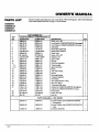
PARTS
LIST
MANUAL
This list contains replaceable parts used in your heater. When ordering parts, follow the insf-u_cfions
listed under Replacement Parts on page 17 of this manual.
CGN20TB
CGN20TLB
CGN30TB
CGN30TLB
KEY
NO.
I
2
3
4
5
6
7
8
9
10
11
11-1
11-2
12
13
14
15
16
17
18
19
20
21
22
23
24
PART NUMBER FOR
CGN20TB/CGN20TLB
CGN30TB/CGN3OTLB
20f000 Btldl-lr
098304-01
098742-03
098742-19
103476-01
101108-01
104189-01AA
098260-09
M 11084-26
104618-01BR
098271-03
098249-01
099440-05
098514-01
098594-01
103446-01
099387-03
103845-06
099066-01
099415-07
099553-01
103255-01
103256-01
098522-10
104617-03
104617-05
997159-04
M 11084-38
NJF-8C
DESCRIPTION
30_000 Btu/Hr
098304-01
098742-04
098742-20
103476-02
101108-01
104189-02AA
098260-10
M 11084-26
104618-02BR
098271-03
098249-01
099440-05
098514-01
098594-01
103447-01
099387-03
103845-08
099066-01
099415-11
099553-01
103255-01
103256-01
098522-12
104617-04
104617-O6
097159-04
Ml1084-38
NJF-8C
Screw, #10 x 3/8"
FrontPanel for CGN20TB/CGN30TB (Champagnel
Front Panel for CGN2OTLB/CGN30T!.B (Ivo_)
Grill Guard
Removable Speed Clip
Bottom Glass Retainer
Glass Panel
i Screw, #10 x 3/8"
Deflector Unit
Ignitor Cable
Nut, M5
ODS/Pilot Assembly
Thermocouple
Ignitor Electrode
Burner
3/16" PilotTubing
Injector
Mounting Bracket
Pressure Regulator
Pilot Shield
3/8" Outlet (Bumer) Tubing
3/8" Inlet Tubing
Thermostat Gas Valve
Cabinet for CGN20TB/CGN30TB (Woodgrain)
Cabinet for CGN20TLB/CGN30TLB (Ivory)
Piezo Ignitor
Screw, #8 x 3/8"
Hex Nut
QTY.
2
1
71
2
1
1
4
1
1
2
1
1
1
1
1
1
1
1
1
1
1
1
1
1
1
2
1
PARTS AVAILABLE -- NOT SHOWN
_o_3_
098305-01
098305-01
098305-05
098305-05
100642-01
100642-01
Control Position Label (CGN20TB/CGN30TB
Champagne)
Control Position Label (CGN20TLB/CGN30TLB
Ivory)
Hardware Assembly
21
1
1
1
BLUE
NOTES
FLAME
NATURAL
GAS
HEATER
OWNER'S
NOTES
,
i
lo,r33_
23
MANUAL
WARRANTY
KEEP
INFORMATION
THIS
WARRANTY
Model
Serial No.
Date Pumhased
Always specify model and serial numbers when communicatingwith the factory.
We reserve the right to amend these specifications at any time without notice. The only warranty applicable is our standard written
warranty. We make no other warranty, expressed or implied.
COMFORT
GLOW
LIMITED
WARRANTY
VENT-FREE
NATURAL
GAS
HEATERS
DESA International warrants this product to be freefrom defects in meterials and components for two(2)yearsfrom the date
of firstpurchase, provided that the product has been properly installed, operatedand maintained in accordance with all applicable
instructions. To make a claim under this warranty the Bill of Sale or cancelled check must be presented.
This warranty is extended only to the original retail purchaser. This warranty covers the cost of part(s) required m restore this
heater to proper operating condition and an allowance for labor when provided by a DESA Authorized Service Center. Warranty
)art(s) MUST be obtained through authorized dealers of this product and/or DESA International who will provide original
factory replacement parts. Failure to use original factory replacement parts voids this warranty. The heater MUST be installed
by a qualified installer in accordance with all local codes and instructions furnished with the unit.
Tiffs warranty does not apply to parts that are not in original condition because of normal wear and tear, orparts that fail or become
damaged as a result of misuse, accidents, lack of proper maintenance or defects caused by improper installation. Travel,
diagnostic cost, labor, transportation and any and all such other costs rela_d to repairing a defective heater will be the
responsibility of the owner.
TO THE FULL EXTENT ALLOWED BY THE LAW OF THE JURISDICTION THAT GOVERNS THE SALE OF THE
PRODUCT; THIS EXPRESS WARRANTY EXCLUDES ANY AND ALL OTHER EXPRESSED WARRANTIES AND
LIMITS THE DURATION OF ANY AND ALL IMPLIED WARRANTIES, INCLUDING WARRANTIES OF MERCHANTABILITY AND FITNESS FOR A PARTICULAR PURPOSE TO TWO (2) YEARS FROM THE DATE OF FIRST
PURCHASE; AND DESA INTERNATIONAL'S LIABILITY IS HEREBY LIMITED TO THE PURCHASE PRICE OF THE
PRODUCT AND DESA INTERNATIONAL SHALL NOT BE LIABLE FOR ANY OTHER DAMAGES WHATSOEVER
INCLUDING INDIRECT, INCIDENTAL OR CONSEQUENTIAL DAMAGES.
Some states do not allow a limitation on how long an implied warranty lasts or an exclusion or limitation of incidental or
consequential damages, so the above limitation on impfied warranties, or exclusion or limitation on damages may not apply to you.
This warranty gives you specific legal rights, and you may also have other rights that vary from state to state.
F°ri°f°=atinn
ah°°tw--tY
write:
DESA
INTERNATIONAL
2701 Industrial Drive
P.O. Box 90004
Bowling
Green,
KY 42102-9004
llllll
IIIIglHH
104331 01
NOT A UPC
104331-01
REV. A
02/98