1
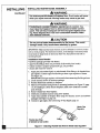
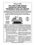
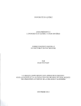
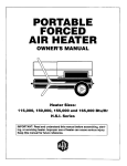
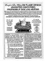
YELLOW FLAME DESIGN
UNVENTED (VENT-FREE)
PROPANE/LP GAS LOG HEATER
IManuaily-Controlled
Models Also Designed Certified as Vented Decorative Appliance)
Thin apphance may be installed in an aftermarket* manufactured
(mobile) home, where
not prohibited by state or local codes. This appliance is only for use with the type of gas
indicated on the rating plate. This appliance is not convertible for use with other gases.
* Aftermarket: Completion of safe, not for purpose of resale, from the manufacturer
OWNER'S
OPERATION AND INSTALLATION
MANUAL
24" and 30"
ThermostaticallyControlled Models
18", 24", and
30" Variable
ManuallyControlled
Models
CGD3924PT
CGD3930PT
CGD3018P
CGD3924P
CGD3930P
Patent Pending
WARNING:
If the
information
in this
manual is not followed exactly, a fire or
explosion
may result causing property
damage, personal injury, or loss of life.
u
Do not store or use gasoline or other
flammable vapors and liquids in the
vicinity of this or any other appliance.
WHAT TO DO IF YOU SMELL GAS
• Do not try to light any appliance.
• Do not touch any electrical switch;
do not use any phone in your building.
• Immediately call your gas supplier
from a neighbor's phone. Followthe
gas supplier's Instructions.
• If you cannot reach your gas supplier, call the fire department.
Installation and service must be performed by a qualified installer, service
agency, or the gas supplier.
WARNING: Improper installation, adjustment, alteration, service, or maintenance
can cause Injury or property damage.
Refer to this manual for correct installation and operational procedures. For assistance or additional information consult a qualified installer, service agency,
or the gas supplier.
WARNING: This gas log set is for installation in a masonry solid fuel buming fire-
plar_, a U.L. listed manufactured solid fuel
burning fireplace or an AGA design certP
fled vent-free firebox listed for use with
these gas log models (Including CGFB32C
and CGFB32NC series)°
WARNING: This Is an unvented gas-fired
heater. It uses air (oxygen) from the room
in which it is installed. Provisions for adequate combustion and ventilation air must
be provided. Refer to Air for Combustion
and Ventilation section in this manual.
Save this manual for future reference.
CONTENTS
SECTION
PAGE
Safety Information ................................................................................... 2
Product Identification ..............................................................................
4
Local Codes .............................................................................................
4
Unpacking ................................................................................................
Product Features ......................................................................................
Air for Combustion and Ventilation ........................................................
4
4
5
Installing ..................................................................................................
8
Check Gas Type ...............................................................................
8
Installation and Clearances (Vent-pree Operation Only) ................. 9
Installing Damper Clamp Accessory for Vented Operation
SAFETY
INFORMATION
............ 13
Installing Heater Base Assembly .....................................................
Connecting to Gas Supply ................................................................
14
15
Checking Gas Connections ..............................................................
Installing Logs ..................................................................................
17
19
Operating Heater (Manually-Controlled Models) ...................................
Operating Heater (Thermostatically-Controlled
Models) .......................
20
22
Inspecting Burners ...................................................................................
Cleaning and Maintenance ......................................................................
24
25
Troubleshooting .......................................................................................
Optional Positioning of Thermostat Sensing Bulb ..................................
Technical Service ....................................................................................
25
29
31
Specifications ..........................................................................................
Service Hints ...........................................................................................
31
31
Replacement Parts ...................................................................................
Parts Central ............................................................................................
32
32
Accessories ..............................................................................................
Illustrated Parts Lists ...............................................................................
33
34
Warranty Information ..............................................................................
Back Cover
A WARNINGS
IMPORTANT: Read this owner's manual carefully and completely before
trying to assemble, operate, or service this heater. Improper use of this
heater can cause serious injury or death from burns, fire, explosion,
electrical shock, and carbon monoxide poisoning.
A DANGER
Carbon monoxide peisoning
may lead to deatht
Carbon Monoxide Poisoning: Early signsof carbon monoxide poisoningresemble
the flu, with headaches, dizziness, or nausea. If you have these signs, the heater may not
be working properly. Get fresh mr at once. Have heater serviced. Some people are more
affected by carbon monoxide than others. These include pregnant wome.n, people with
heart or lung disease or anemia, those under the influence of alcohol, and those at high
altitudes.
Propane
Gas: Propane gas is odorless. An odor-making
agent is added to the gas. The
odor helps you detect a gas leak. However, the odor added to the gas can fade. Gas may be
present even though no odor exists.
Make certain you read and understand all Warnings. Keep this manual for reference. It is
your guide to safe and proper operation of this heater.
[ _J_
Safety Information continues on next page
10_04
SAFETY
INFORMATION
Continued
WARNINGS
Continued
WARNING: Any change to this heater or its controls can be dangerous. "
1. This appliance is only for use with the type of gas indicated on the rating plate. Thi:
appliance is not convertible for use with other gases,
2. Do not place propane (LP) supply tank(s) inside any structure. Locate propane (LP) supply
tank(s) outdoors.
3. To prevent performance problems, do not use propane fuel tank ofless than 100 lbs. capacity.
4. If you smell gas
• shut off gas supply
• do not try to light any appliance
• do not touch any electrical switch; do not use any phone in your building
• immediately call your gas supplier from a neighbor' s phone. Follow the gas supplier' s
instructions
• if you cannot reach your gas supplier, call the fire department
5. This heater shall not be installed in a bedroom or bathroom unless installed as a vented
appliance (Variable Manually-Controlled Models Only) (see page 13).
6. Never install the heater
• in a recreational vehicle
• where curtains, furniture, clothing, or other flammable objects are less than 36 inches
from the front, top, or sides of the heater
• in high traffic areas
• in windy or drafty areas
7. Before installing in a solid fuel burning fireplace, the chimney flue and firebox must be
cleaned of soot, creosote, ashes and loose paint by a qualified chimney cleaner. Creosote
will ignite if highly heated. Inspect chimney flue for damage. If damaged, operate heater
with flue damper closed.
8. If fireplace has glass doors, never operate this heater with glass doors closed. Ifyou operate
heater with doors closed, heat buildup inside fireplace will cause glass to burst. Also if
fireplace opening has vents at the bottom, you must open the vents before operating heater.
9. You must operate this heater with a fireplace screen in place. Make sure fireplace screen
is closed before running heater.
!0. This log heater is designed to be smokeless. If logs ever appear to smoke, turn off heater
and call a qualified service person. Note: During initial operation, slight smoking could
occur due to log curing and heater burning manufacturing residues.
11. Do not allow fans to blow directly into the fireplace. Avoid any drafts that alter burner
flame patterns. Ceiling fans can create drafts that alter burner flame patterns. Altered
burner patterns can cause sooting.
12, Do not use a blower insert, heat exchanger insert or other accessory not approved for use
with this heater.
13. This heater needs fresh, outside air ventilation to run properly. This heater has an oxygen
depletion sensor (ODS) pilot light safety system. The ODS shuts down the heater if not
enough fresh air is available. See Air for Combustion and Ventilation, pages 5 through 8.
If heater keeps shutting off, see Troubleshooting, pages 25 through 28.
14. Do not run heater
• where flammable liquids or vapors are used or stored
• under dusty conditions
15. Do not use this heater to cook food or burn paper or other objects.
16. Never place any objects on the heater.
17. Heater base assembly becomes very hot when running heater. Keep children and adults
away from hot surface to avoid burns or clothing ignition. Heater will remain hot for atime
after shutdown. Allow surface to cool before touching.
18. Carefully supervise young children when they are in the room with heater.
19. Do not use heater if any part has been exposed to or under water. Immediately call a
qualified service technician to inspect the room heater and to replace any part of the c onU'ol
system and any gas control which has been under water.
20. Do not operate heater if any log is broken. Do not operate heater if a log is chipped (dimesized or larger).
21. Turn heater off and let cool before servicing. Only a qualified service person should
service and repair heater.
22. Operating heater above elevations of 4,500 feet could cause pilot outage,
I0_04
m_
PRODUCT
IDENTIFICATION
Crossover Log
Log.
Front Log
Ignitor
Contr¢
LOCAL CODES
Figure 1 - Vent-Free Gas Log Heater
Install and use heater with care. Follow all local codes. In the absence of local
codes, use the latest edition of The National
known as NFPA 54*.
*Available
from:
Ameriean
National
Note: Where
Fuel Gas Code ANSI Z223, also
National Standards Institute,
1430 Broadway
New York, NY 10018
Fire Protection Association,
Batterymarch Park
Quincy, MA 02269
listed vented decorative
logs are required,
Inc.
Inc.
thermostat
operation
is not
permitted.
UNPACKING
1. Remove logs and heater base assembly from carton. Note: Do not pick up heater
base assembly by burners. This could damage heater. Always handle base
assembly by grate.
2. Remove all protective packaging applied to logs and heater for shipment.
3. Check all items for any shipping damage. If damaged, promptly inform dealer
where you bought heater.
PRODUCT
FEATURES
Operation
This heater is clean burning. It requires no outside venting.
There is no heat loss out a
vent or up a chimney. Heat is generated by realistic dancing, yellow flames. This heater
is designed for vent-free operation with flue damper closed. State and local codes in
some areas prohibit the use of vent-free heaters. You can operate heater as a vented
product by opening flue damper.
Safety Pilot
This heater has a pilot with an Oxygen Depletion Sensor Shutoff System (ODS).
The ODS/pilot is a required feature for vent-free room heaters. The ODS/pilot shuts
9ff the heater if there is not enough fresh air.
Piezo Ignition System
This heater has a piezo ignitor. This system requires no matches, batteries, or other
sources to light heater.
70a_4
AIR FOR
COMBUSTION
AND
VENTILATION
WARNING
This heater shall not be installed
in a confined
space
unless
provisions are provided for adequate combustion
and ventilation
air. Read the following instructions
to insure proper fresh air for
this and other fuel-burning
appliances
in your home.
Today's homes are built more energy efficient than ever. New materials, increased
insulation, and new construction
methods help reduce heat loss in homes. Home
owners weather strip and caulk around windows and doors to keep the cold air out
and the warm air in. During heating months, home owners want their homes as
airtight as possible.
While it is good to make your home energy efficient, your home needs to breathe.
Fresh air must enter your home. All fuel-burning appliances need fresh air for
proper combustion and ventilation.
Exhaust fans, fireplaces, clothes dryers, and fuel burning appliances draw air from
the house to operate. You must provide adequate fresh air for these appliances.
This will insure proper venting
of vented fuel-burning
appliances.
PROVIDING ADEQUATE VENTILATION
The following is excerpts from National Fuel Gas Code. NFPA 54/ANSI
Section 5.3, Air for Combustion and Ventilation.
Z223.1,
All spaces in homes fall into one of the three following ventilation classifications:
1. Unusually Tight Construction;
2. Unconfined
Space; 3. Confined Space.
The information on pages 5 through 7 will help you classify your space and provide
adequate
ventilation.
Unusually
Tight Construction
The air that leaks around doors and windows may provide enough fresh air for
combustion and ventilation. However, in buildings of unusually tight construction
you must provide
additional
fresh air.
Unusually tight construction Is defined as construction where:
a. walls and ceilings exposed to the outside atmosphere have a continuous water vapor retarder with a rating of one perm (6x10 "11per
pa.aec.m =) or less with openings gasketed or sealed and
b. weather stripping has been added on openable windows and doors and
c. caulking or sealants are applied to areas such as joints around window
and door frames, between sole plates and floors, between wall-ceiling
Joints, between wall panels, at penetrations for plumbing, electrical, and
gas lines, and at other openings.
If your home meets all of the three criteria above, you must provide additional fresh air. See Ventilation Air From Outdoors, page 7.
If your home does not meet all of the three criteria above, proceed
Confined
and Unconfined
Space
The National Fuel Gas Code (ANSIZ223.1,
space as a space whose volume
to page 6.
1992 Section 5.3) defines a confinod
is less than 50 cubic feet per 1,000 Btu per hour (4.8
m 3 per kw) of the aggregate input rating of all appliances installed in that space and
an unconfined space as a space whose volume is not less than 50 cubic feet per 1,000
Btu per hour (4.8 m 3per kw) of the aggregate input rating of all appliances installed
in that space. Rooms communicating directly with the space in which the appliances
are installed*, through openings not furnished with doors, are considered a part of the
unconfined space.
* Adjoining
ventilation
10_604
rooms are communicating
grills between them.
only if there are doorless passageways
or
Continued
_"
AIR FOR
COMBUSTION
AND
VENTILATION
Continued
DETERMINING
Determining
AIR FLOW FOR HEATER
LOCATION
if You Have a Confined or Unconfined
Space-
Use this work sheet to determine if you have a confined or unconfined space.
Space:
doorless
Includes the room in which you will install heater plus any adjoining
passageways
or ventilation grills between the rooms.
rooms
with
1. Determine the volume of the space (length x width x height).
Length x Width x Height =
cu. ft. (volume of space)
Example:
Space size
20 ft. (length) x 16 ft. (width) x 8 ft. (ceiling height) =
2560 cu. ft. (volume of space)
If additional ventilation to adjoining room is supplied with grills or openings, add the
volume of these rooms to the total volume of the space.
2. Divide the space volume by 50 cubic feet to determine the maximum Btu/Hr the space
can support.
(volume of space) + 50 cu. ft. = (Maximum Btu/Hr
the space can support)
Example: 2560 cu. ft. (volume of space) + 50 cu. ft. = 51.2 or 51,200 (maximum
Btu/Hr the space can support)
3. Add the Btu/Hr of an fuel burning appliances in the space.
Example:
Vent-free heater
Gas water heater*
Gas furnace
Btu/Hr
Btu/Hr
Btu/Hr
Vented gas heater
Gas fireplace logs
Other gas appliances*
Total
+
=
Btu/Hr
Btu/Hr
.Btu/Hr
Btu/Hr
Gas water heater
Vent-free heater
Total
+
=
40,000
39,000
79,000
* Do not include direct-vent gas appliances. Direct-vent
outdoors and vents to the outdoors.
Btu/Hr
Btu/Hr
Btu/Hr
draws combustion air from the
4. Compare the maximum Btu/Hr the space can support with the actual amount of Btu/Hr
used.
Btu/Hr (maximum the space can support)
Btu/Hr (actual amount of Btu/Hr used)
Example:
51,200
79,000
Btu/T-Ir(maximum the spacecan support)
Btu/Hr (actualamount of BtuiHr used)
The space in the above example is a confined space because the actual Btu/Hr used is more
than the maximum Btu/Hr the space can support. You must provide additional fresh air.
Your options are as follows:
A. Rework wurksheet, adding the space of an adjoining room. If the extra space provides
an unconfined space, remove door to adjoining room or add ventilation grills between
rooms. See Ventilation Air From Inside Building, page 7.
B. Vent room directly to the outdoors. See Ventilation Air From Outdoors, page 7.
C. Install a lower Btu/Hr heatar, if lowar Btu/Hr size makes room unconfined.
Iftbe actual Btu/Hr used is less than the maximum Btu/I-Irthe space can support, the space
is an unconfined space. You will need no additional fresh air ventilation.
AIR FOR
COMBUSTION
AND
VENTILATION
Continued
WARNING
If the area in which the heater
may be operated
is smaller
than
that defined as an unconfined space, provide adequate combustion and ventilation air by one of the methods described in the
National Fuel Gas Code, ANSI Z223.1, 1992, Section 5.3 or applicable local codes.
VENTILATION
AIR
Ventilation Air From Inside Building
This fresh air would come from an adjoining unconfined space. When ventilating to an
adjoining unconfined space, you must provide two permanent openings: one within 12" of the
ceiling and one within 12" of the floor on the wall connecting the two spaces (see options 1
and 2, Figure 2). You can also remove door into adjoining room (see option 3, Figure 2).
Follow the National Fuel Gas Code NFPA 54/ANSI Z223.1, Section 5.3, Air for Combustion
2nd Ventilation for required size of ventilation grills or ducts.
WARNING
Rework
worksheet,
adding
the space
of the adjoining
unconfined
space. The combined spaces must have enough fresh air to supply all
appliances in both spaces.
Ven-Grills
Ventila_on Gdlls
Into Adjoining
Room,
Op_on 1
O_
Remove II
Door into li
Into Adjoining Room.
Op_on 2
Adjoining
Room, il
OptionOll
Figure 2 - Ventilation Air from Inside Building
Ventilation
Air From Outdoors
Provide extra fresh air by using ventilation grills or ducts. You must provide two permanent openings: one within 12" of the ceiling and one within 12" of the floor. Connect
these items directly to the outdoors or spaces open to the outdoors. These spaces include
attics and crawl spaces.
IMPORTANT: Do not provide openings for inlet or outlet air into attic if attic has a thermostatcontrolled power vent. Heated air entering the attic will activate the power vent.
I
Outer
/_ir
TO Attic
==========
To
c"
spa=
I
Inka/U¢
n
I
Verl_llted
Cr,_s_=
I
'ure 3 - Ventilation Air from Outdoors
IF4
INSTALLING
t
A qualified
service person must
NOTICE
install heater. Follow all local codes.
NOTICE
State or local codes may only allow operation of this appliance
vented configuration.
Check your state or local codes.
in a
WARNING
Before installing in a solid fuel burning fireplace, the chimney flue
and firebox must be cleaned of soot, creosote, ashes and loose paint
by a qualified
chimney
cleaner.
Creosote
Inspect chimney flue for damage.
flue damper closed.
will ignite if highly heated.
If damaged,
operate
heater with
WARNING
Seal any fresh air vents or ash clean-out doors located on floor or wall
of fireplace. If not, drafting may cause pilot outage or sooting. Use a
heat-resistant
sealant. Do not seal chimney flue damper.
WARNING
Never install the heater
• in a bedroom or bathroom unless
• ance (Variable Manually-Controlled
• in a recreational vehicle
installed as ave, nted appliModels Only) (see page 13)
• where curtains, furniture, clothing, or other flammable
objects
are less than 36 inches from the front, top, or sides of the heater
• in high traffic areas
• in windy
or drafty areas
CAUTION
This heater creates
to wall surfaces
warm air currents.
next to heater.
These
Installing
currents
heater
move heat
next to vinyl or
cloth wall coverings or operating heater where impurities
(such as tobacco smoke) exist, may discolor walls.
in the air
IMPORTANT: Vent-free heaters add moisture to the air. Although this is beneficial,
installing heater in rooms without enough ventilation air may cause mildew to form
from too much moisture. See Air for Combustion and Ventilation, pages 5 through 7.
CHECK GAS TYPE
Use only propane gas. If your gas supply is not propane, do not install heater. Call
dealer where you bought heater for proper type heater.
INSTALLING
INSTALLATION
AND CLEARANCES
(Vent-Free
Operation
Only)
Continued
Maintain the minimum clearances.
If you can, provide
WARNING
ances from floor, ceiling, and adjoining wall.
MINIMUM
FIREPLACE
clear-
CLEARANCE
TO COMBUSTIBLE
MATERIALS
Log Size
Side Wall
Ceiling
18,24,30
16 •
42"
LOG SIZING
greater
REQUIREMENTS
Log
Minimum Firebox Size
Size
18"
Height
17"
Depth
14"
Front Width
20"
24"
30"
17"
17"
14 =
14"
26"
32"
Carefully follow the instructions below. This will ensure safe installation into a
masonry, U.L. listed manufactured
fireplace, or AGA design certified vent-free
firebox listed for use with these models.
Minimum
Wall and Ceiling Clearances
(see Figure 4)
A. Clearances from the side of the fireplace opening to any combustible
should not be less than 16 inches.
B. Clearances from the top of the fireplace
less than 42 inches.
opening
to the ceiling
wall
should not be
42"
16
i
Left and Right
Sides
/
/I
Figure 4. Minimum Clearance to Well end Ceiling
Continued
!
INSTALLING
Continued
NOTICE
You may use this heater as a vented product. If so, you must
always run heater with chimney flue damper open. If running
heater with damper open, non-combustible
material above fireplace opening is not needed. Go to Installing
Accessory
for Vented Operation, page 13.
Minimum
Non-Combustible
Material
Damper
Clamp
Clearances
If Not Using Mantel
Note: If using a mantel, go to page 11. If not using a mantel,
tion on this page.
follow the informa-
You must have non-combustible
material(s) above the fireplace opening. Noncombustible materials (such as slate, marble, tile, etc.) must be at least 1/2 inch
thick. With sheet metal, you must have non-combustible
material behind it. Noncombustible
material must extend at least 8" up (for all models). If non-combustible material is less than 12", you must install the fireplace hood accessory (24"
and 30" models only). See chart below and Figure 5 for minimum clearances.
IMPORTANT: If you cannot meet these minimum clearances, you must operate
heater with chimney flue damper open. Go to Installing Damper Clamp Accessory
for Vented Operation, page 13.
Non-Combustible
Material Distance (A)
Requirements for
Safe Installation
12" or more
Non-combustible material okay.
Between 8" and 12"
24" or 30" Models: Install fireplace hood accessory
(GA6050 or GA6052, see Accessories, page 33).
18" Model: Non-combustible matedal okay.
Less than 8"
Non-combustible matedal must be extended to at
least 8". See Between 8"and 12", above. If you
cannot extend material, you must operate heater
with flue damper open.
Heat Resistant -_
Material
I
ml
Figure 5 - Heat Resistant Material (Slate, Marble, Tile, etc.) Above Fireplace
I03604
INSTALLING
Minimum
Non-Combustible
Material
Clearances
(Continued)
If Using Mantel
Continued
You must have non-combustible
material(s) above the fireplace opening. Noncombustible materials (such as slate, marble, tile, etc.) must be at least 1/2 inch
thick. With sheet metal, you must have non-combustible
material behind it. Noncombustible material must extend at least 8" up (for all models). If non-combustible material is less than 12", you must install the fireplace hood accessory (24"
and 30" models only). Even if non-combustible
material is more than 12", you
may need the hood accessory to deflect heat away from your mantel shelf. See
chart below and Figures 6 and 7 for minimum clearances.
IMPORTANT." If you cannot meet these minimum clearances, you must operate
heater with chimney flue damper open. Go to Installing Damper Clamp Accessory for Vented Operation, page 13.
Non-Combustible
Material Distance (A)
Requirements for
Safe Installation
12" or more
Non-combustible
Between 8" and 12"
24" or 30" Models: Install fireplace hood accessory
(GA6050 or GA6052, see Accessories, page 33).
18" Model: Non-combustible material okay.
Less than 8"
Non-combustible material must be extended to at
material okay.
least 8". See Between 8" and 12", above. If you
cannot extend material, you must operate heater
with flue damper open.
Mantel Clearances
In addition to meeting non-combustible
material clearances, you must also meet
required clearances between fireplace opening and mantel shelf. If you do not
meet the clearances listed below, you will need a hood.
Determining Minimum Mantel Clearance
If you meet minimum
clearance between
ing, a hood is not required
mantel
shelf and top of f'weplace open-
(see Figure 6).
Mantel Shelf
Mantel Shelf
j
Underside of
All minimum
distances are
in inches
m_
MinimumNon- _
i
Combustiblfl
,,
(A)
Matedal
/
12"
20"
241,2•
271,2 •
30" _
Log Set
24"/30" Models
8"
14"
163/4 ,
181Q"
20" _
18" Model
#
/
/
Top of Fireplace
_
MinimumNon.
Combustible
/
Distancesto
Underside of
MaterialHeight
Mantel
Opening
i
I
Figure 6. Minimum Mantel Clearances Without Using Hood
Continued
,,,k
_l_
I
INSTALLING
Continued
Determining Minimum Mantel Clearance When Using a Hood
If minimum clearances in Figure 6 are not met, you must have a hood. When
using a hood there are still certain minimum mantel clearances required. Follow
minimum clearances shown in Figure 7 when using hood.
Mantel Sheff
Underside of
Mantel Sheff
L
m'_m
All minimum
distances are
in inches
Minimum NonCombuslJble
Material
Log Set
12"
15"
18"
!0"<--18",
24", 30"
Models
r
r
k
Top of Fireplace
Opening
HOOd
(GA6050, GA6052)
Distances to
Underside of
Mantel
Figure 7- Minimum Mantel Clearances When Using Hood
If your installation
does not meet the above minimum
clearances,
you must:
• operate the logs only with the flue damper open, OR
• raise the mantel to an acceptable height, OR
• remove the mantel.
Floor Clearances
A. If installing appliance on the floor level, you must maintain
distance of 14" to combustibles (see Figure 8).
the minimum
]
Combustible
Material
14"
\\\\\\\\\1
_"_'Non-Combustible
Figure 8 - Minimum Fireplace Clearances
B.
If combustible
appliance
materials
Material
ff Installed at Floor Level
are less than 14" to the fireplace, you must install
at least 5" above the combustible
flooring
(see Figure 9).
Hearth
Combustible
Matede[
Min.
_l_
,,
Figure 9 - Minimum Fireplace Clearances
Above Combustible
Flooring
1O36O4
INSTALLING
INSTALLING
VENTED
ContMued
DAMPER
CLAMP
ACCESSORY
FOR
OPERATION
Note: When used as a vented heater, appliance
fuel burning
material.
fireplace
with a working
If your heater is a manually
controlled
must be installed
flue and constructed
model,
only in a solid-
of non-combustible
you may use this heater as a vented
product. There are three reasons for operating your heater in the vented mode.
1. The fireplace does not meet the clearance to combustibles
requirements
for
vent-free operation.
2. State or local codes do not permit vent-free operation.
3. You prefer vented operation.
If reasons number 1or 2 above apply to you, you must permanently open chimney flue
damper. You must install the damper clamp accessory (to order, seeAccessories,
page
33). This will insure vented operation (see Figure 10). The damper clamp will keep
damper
open. Installation
instructions
are included
with clamp accessory.
See chart below for minimum permanent flue opening you must provide. Attach
damper clamp so the minimum permaneni flue opening will be maintained at all times.
Chimney
Height (ft.)
6' to 15'
15' to 30'
Minimum Permanent
Flue Opening ($q. ins.)
39 sq. inches
29 sq. inches
Area of Various Standard Round Flues
Diameter (ins.)
5"
6"
7"
8"
Area (sq. ins.)
20
29
39
51
sq.
sq.
sq.
sq.
inches
inches
inches
inches
Damper F
Clamp
Damper
Oon,por
Masonry Fireplace
Manufactured
Fireplace
Figure 10- Attaching Camper Clamp
Continued
,o_04_
m
Ill
INSTALLING
INSTALLING
HEATER
BASE
ASSEMBLY
WARNING
Continued
You must secure this heater to fireplace
when you adjust controls.
Moving
floor. If not, heater will move
heater
may cause a gas leak.
WARNING
if installing in a sunken fireplace, special care is needed. You
must raise the fireplace floor to allow access to heater control
panel. This will insure adequate air flow and guard against sooting. Raise fireplace floor with non-combustible
material. Make
sure material is secure.
CAUTION
Do not pick up heater base assembly
damage
heater. Only handle
by the burner. This could
base assembly
IMPORTANT: Make sure the heater burners
by grates.
are level. If heater is not level, heater
will not work properly. For thermostat models, avoid damage to thermostat bulb.
Avoid nicks or sharp bends in thermostat bulb wire. Keep thermostat bulb in
mounting
bracket.
Installation
•
•
•
•
Items Needed
hardware package (provided with heater)
approved flexible gas hose (not provided) (if allowed by local codes)
sealant resistant to propane (propane/LP)
gas, not provided
electric drill with 3/16" drill bit
1. Apply pipe joint sealant lightly to male threads of the fitting to be threaded into
gas regulator. Connect approved flexible gas hose to gas regulator of heater
(see Figure 11).
IMPORTANT:Hold gas regulator with wrench when connecting flexible gas hose.
2. Locate masonry screws in hardware package.
3. Position heater base assembly in fireplace.
4. Mark screw locations through holes in mounting brackets (see Figure 12, page
15). If installing in a brick-bottom fireplace, mark screw locations in mortar
5.
6.
7.
joint of bricks.
Remove heater base from fireplace.
Drill holes at marked locations using 3/16" drill bit.
Attach base assembly to fireplace floor using two masonry
package) (see Figure 12, page 15).
8. Connect to gas supply. See Connecting
To Gas Supply,
page 15.
(_
Regulator
_
__eeter
Figure
,,
11 - Attaching
Gas
Fitting
Flexible Gas Hose
(if allowed by local codes)
! _L_
screws (in hardware
Flexible
Gas Hose
to Heater
Gas Regulator
,,_
INSTALLING
Continued
Mo2
Figure 12 - Attaching Base Assembly to Fireplace Floor
CONNECTING TO GAS SUPPLY
NOTICE
A qualified service person
Follow all local codes.
must connect
heater to gas supply.
CAUTION
Never connect heater directly
requires an external regulator
regulator
between
to the propane
(not supplied).
the heater and propane
supply. This heater
Install the external
supply.
Installation Items Needed
Before installing heater, make sure you have the items listed below.
• external regulator (supplied
installer, see page 16)
• piping (check local codes)
by
• sealant (resistant to propaneJLP gas)
• manual shutoff valve *
•
•
•
•
test gauge connection *
sediment trap
tee joint
pipe wrench
* An A.G.A. design-certified
manual shutoffvalve with 1/8" NFFtap
alternative to test gauge connection. Purchase the optional A.G.A.
manual shutoff valve from your dealer. See Accessories,
page 33.
is an acceptabh
design-eertifiex
Continue
INSTALLING
Continued
The installer must supply an external regulator. The external regulator will reduce
incoming gas pressure. You must reduce incoming gas pressure to between 11 and
14 inches of water. If you do not reduce incoming gas pressure, heater regulator
damage could occur. Install external regulator with the vent pointing down as
shown in Figure 13. Pointing the vent down protects it from freezing rain or sleet.
Propane
Supply Tank
T
\
E erna,
Reou,ator
* <o*"-_
6"000
€
.-, L •
Vent Pointing
Down
Figure 13 - External Regulator With Vent Pointing Down
CAUTION
Use only new, black iron or steel pipe. Internally-tinned
copper
tubing may be used in certain areas. Check your local codes. Use
pipe of 1/2" diameter or greater to allow proper gas volume to
heater. If pipe ts too small, undue loss of pressure will occur.
Installation must include a manual shutoff valve, union, and plugged 1/8" NPT tap.
Locate NPT tap within reach for test gauge hook up. NPT tap must be upstream
from heater (see Figure 14, page 17).
Apply pipe joint sealant lightly to male threads. This will prevent excess sealant
from going into pipe. Excess sealant in pipe could result in clogged heater valves.
CAUTION
Use pipe joint sealant that is resistant
to liquid petroleum
(LP) gas.
Install sediment trap in supply line as shown in Figure 14, page 17. Locate sediment trap where it is within reach for cleaning. Locate sediment trap where trapped
matter is not likely to freeze. A sediment trap traps moisture and contaminants.
This keeps them from going into heater controls. If sediment trap is not installed or
is installed wrong, heater may not run properly.
INSTALLING
Contmued
CAUTION
Avoid damage to regulator. Hold gas regulator
connecting
it to gas piping and/or fittings.
From
Gas Meter
(5" W.C*** to
10.5" W.C,
with wrench
when
A.G.A. Design-Certified
Manual Shutoff Valve
With 1/8" NPT Tap*
,_
// //
/
Pressure)
Gas Hose Flexible
(if allowed
Approved
by local codes)
/
3" Minimum
Sediment
Trap
Figure 14 - Gas Connection
* Purchase theoptional A.G.A. design-certified manual shutoff valve from your dealer
See Accessories, page 33.
_'* Minimum inlet pressure for purpose of input adjustment.
CHECKING
GAS CONNECTIONS
WARNING
Test all gas piping and connections
servicing. Correct all leaks at once.
for leaks after installing
or
WARNING
Never use an open flame to check for a leak. Apply a mixture of
liquid soap and water to all joints. Bubbles forming show a leak.
Correct all leaks at once.
CAUTION
Make sure external regulator has been Installed between propane
supply end heater. See guidelines under Connecting
to Gas Supply, page 15.
Pressure Testing Gas Supply Piping
Test Pressures In Excess Of 1/2 PSIG
system
1: DisconneCt heater and its individual manual shutoff valve from gas supply
piping system. Pressures in excess of 1/2 psig will damage heater regulator.
2. Cap off open end of gas pipe where manual shutoff valve was connected.
Continued
Ia_6_
I
INSTALLING
Con_nued.
3. Pressurize supply piping system by either using compressed
opening propane supply tank valve.
4. Check all joints of gas supply piping system. Apply mixture
water to gas joints• Bubbles forming show a leak.
5. Correct all leaks at once.
6.
Reconnect
air of
of liquid soap and
heater and manual shutoff valve to gas supply. Check reconnected
fittings for leaks.
Test Pressures
Equal To or Less
1. Close manual shutoff valve (seeFigure
2. Pressurize
Than
15).
1/2 PSIG
supply piping system by either using compressed
air or opening
3.
propane supply tank valve.
Check all joints from propane
4.
16). Apply mixture of liquid soap and water to gas joints. Bubbles
show a leak.
Correct all leaks at once.
Pressure
Testing
Heater
supply tank to manual
Gas
shutoff valve (see Figure
forming
Connections
1. Open manual shutoff valve (see Figure 15).
2. Open propane supply tank valve.
3. Make sure control knob of heater is in the OFF position.
4.
Check all joints from manual shutoff valve to control valve (see Figure 16).
Apply mixture of liquid soap and water to gas joints. Bubbles forming show a
leak.
5.
Correct
all leaks at once.
6.
Light heater (see Operating Heater, pages 20 through 22 [manually-controlled
models] or pages 22 through 24 [thermostatically-controlled
models]). Check
all other internal joints for leaks.
7. Turn offheater (see To Turn OffGas to Appliance, page 21 [manually-controlled models] or page 24 [thermostatically-controlled
models]).
Shutoff
Valve
sed
Figure 15 - Manual Shutoff Valve
Manual
Thermostat Gas Valve or
• "_ Shutoff
Control Valve Location
,//
....
Valve
Propane
/
,,_
///,
"/
Supply Ta__. __
/
• //
:_._ -To;..-=
_ ,L_,
i
i
i
,
i
i
,ff*_.._.... -,-_,..._.._,
Figure 16. Checking Gas Joints
i
i
_
i
_
i
INSTALLING
INSTALLING
LOGS
Continued
WARNING
Failure to position the parts in accordance with these diagrams or failure
to use only parts specifically approved with this heater may result in
property damage or personal injury.
Each log is marked with a number. These numbers will help you identify the log
when installing. It is very important to install these logs exactly as instructed. Do
not modify logs. Only use logs supplied with beater.
1. Locate pegs on the bottom of back log (#1). Slide these pegs into the holes in
the grate base behind the burner (see Figure 17).
2. Place the base ofthe middle log (#2) in the U-shaped slots of the grate base in front
of the back log. The cutout on the right of the middle log should fit over the burner
(see Figure 18), Make sure the front of the middle log is resting on the tabs of the
grate base and the cutout area is centered over the burner "U" bend.
3. Locate the recesses on the back of the front log (#3). Fit these recesses between
the posts of the grate base (see Figure 19).
4. Locate the notches in the bottom of the crossover log (#4). Place the crossover
log on top of the middle log and front log. Make sure the notches of the crossover log lines up with rectangular
(see Figure 20).
/_"_Back
Peg _....
Hole in
GrateBase<_._.._
knobs on top of the middle and front logs
Log (#1)
(_J_j
_
_
,
'-..
:1
_ _
_,,,,.____
_ .
Middle Log (#2)
"(<.:""
-.1..
_.'.-.,
_
"at
"
L_'_---%_,_"_%_.._.
_I
_J
._./
j ' Cut°ut
"_"_I
U-Shaped
Slot
td
Figure 17- Installing Back Log (#1)
Front Log (#3)
"_1<_'_
Flgure19
-
. lnstalllng_Front :;#3)
Figure 18 - Installing Middle Log (#2)
Notches
_
Rectangular
Fl::::
Crossover
_-,_p.,_
. lnstalllng
f
Cr "_o_ver Log (#_
OPERATING
HEATER.
Manually-
Controlled Models
1
FOR YOUR SAFETY READ BEFORE
LIGHTING
/
WARNING
If you do not follow these instructions exactly, a fire or explosion may
result causing property damage, personal injury or loss of life,
A.
This appliance has a pilot which must be lighted by hand. When lighting the pilot,
follow these instructions exactly.
B. BEFORE LIGHTING smell all around the appliance area for gas. Be sure to smell
next to the floor because some gas is heavier than air and will settle on the floor.
WHAT TO DO IF YOU SMELL GAS
• Do not try to light any appliance.
• Do not touch any electric switch; do not use any phone in your building.
• Immediately call your gas supplier from a neighbor's phone. Follow the gas
supplier's instructions.
• If you cannot reach your gas supplier, call the fire department.
C. Use only your hand to push in or turn the gas control knob. Never use tools. If the
knob will not push in or turn by hand, don't try to repair it, call a qualified service
technician or gas supplier. Force or attempted repair may result in a fire or
explosion.
D. Do not use this appliance if any part has been under water. Immediately call a
qualified service technician to inspect the appliance and to replace any part of the
control system and any gas control which has been under water.
LIGHTING
INSTRUCTIONS
WARNING
• If fireplace has glass doors, never operate this heater with glass doors
closed. If you operate heater with doors closed, heat buildup inside
fireplace will cause glass to burst. Also if fireplace opening has vents at
the bottom, you must open the vents before operating heater.
• You must operate this heater with a fireplace screen in place. Make sure
fireplace screen is closed before running heater.
NOTICE
During initial operation of new heater, burning logs will give off a paperburning smell. Orange flame will also be present. Open damper or
window to vent smell. This will only last a few hours.
Note: Homeowners generally prefer to operate their heater with the chimney damper
closed. This will put all the heat into the room. However there may be times you will
desire the full flames of the Hi heat setting but will find the heat output excessive. You
can open the chimney damper (if you have one) fully or partially to release some of
the heat. WARNING: Damper handle will be hot ff heater has been running.
1. STOP! Read the safety information above.
2. Make sure manual shutoff valve is fully open.
3. Press in and turn control knob clockwise
IgnitorButlon\
_
to the OFF position.
_Control
Knob
Figure 21 - Control Knob and Ignitor Button Location
4. Walt five ($) minutes to clear out any gas. Then smell for gas, including near the
floor. I!you smell gas, STOP! Follow "B" in the safety information above. If you
don't smell gas, go to the next step.
OPERATING
5. Slightly depress and turn control knob counterclockwise
HEATER
ManuallyControlled Models
_
to the PILOT
position. Press in control knob for five (5) seronds (see Page 20).
Note: You may be running this heater for the first tim e after hooking up to gas
supply, If so, the control knob may need to be pressed in for 30 seconds. This
will allow air to bleed from the gas system.
6.
Continued
With control knob pressed in, press and release ignitor button. This will light
pfloL The pilot is attached to the burner. If needed, keep pressing ignitor button
until pilot lights.
Note: ff pilot does not stay lit, contact a qualified service person or gas supplier
for repairs. Until repairs are made, light pilot with match. To light pilot with
match, see Manual Lighting Procedure, page 22.
7.
Keep control knob pressed
release control knob.
Note:
in for 30 seconds
If pilot goes out, repeat
after lighting
steps 3 through
pilot. After 30 seconds,
7.
Pilot Bumer
Figure 22 - Pilot
• If control knob does not pop out when released, contact a qualified service
person or gas supplier for repairs.
8. Slightly depress and turn control knob counterclockwise _
to desired
heating level The burner should light. Set control knob to any heat level between
HI and LO.
WARNING
Do not operate heater between PILOT and HIGH positions.
VARIABLE CONTROL OPERATION
The variable control valve can be set to any heat setting and flame height desired, by
simply turning the control knob until that setting is attained. Even the lowest setting
provides realistic, dancing yellow flames. Selecting higher settings produces greater
heat output. This results in increased heating comfort.
CAUTION
Do not try to adjust heating levels by using the manual shutoff valve.
TO TURN OFF GAS TO APPLIANCE
Shutting Off Heater
1. Press in and turn control knob clockwise _
to the HIGH position.
2. Turn control knob clockwise _
to the pilot position.
3. Press in control knob and turn clockwise _
to the OFF position.
Shutting Off Burners Only (pilot stays lit)
1. Turn control knob clockwise _
to the HIGH position.
2. Press in and turn control knob clockwise _
to the pilot position.
Continued
lo_o_
U
OPERATING
HEATER
Continued
OPERATING
HEATER
ThermostaticallyControlled
Models
MANUAL
LIGHTING
PROCEDURE
1. Follow steps 1 through $ under Lighting Instructions, pages 20 and 21.
2. Depress control knob and light pilot with match.
3. Keep control knob pressed in for 30 seconds after lighting pilot. After 30 seconds,
release control knob. Now follow step 8 on page 21.
•
FOR YOUR SAFETY READ BEFORE
LIGHTING
WARNING
if you do not follow these instructions exactly, a fire or explosion may
result causing property damage, personal injury or loss of life.
A.
B.
C.
D.
This appliance has a pilot which must be lighted by hand. When lighting the pilot_
follow these instructions exactly.
BEFORE LIGHTING smell all around the appliance area for gas. Be sure to smell
next to the floor because some gas is heavier than air and will settle on the floor.
WHAT TO DO IF YOU SMELL GAS
• Do not try to light any appliance.
• Do not touch any electric switch; do not use any phone in your building.
• Immediately call your gas supplier from a neighbor's phone. Follow the gas
supplier's instructions.
• If you cannot reach your gas supplier, call the fire department.
Use only your hand to push in or turn the gas control knob. Never use tools. If the
knob will not push in or turn by hand, don't try to repair it, call a qualified service
technician or gas supplier. Force or attempted repair may result in a fire or
explosion.
Do not use this appliance if any part has been under water. Immediately call a
qualified service technician to inspect the appliance and to replace any part of the
control system and any gas control which has been under water.
LIGHTING INSTRUCTIONS
WARNING
• If fireplace has glass doors, never operate this heater with glass doors
closed. If you operate heater with doors closed, heat buildup inside
fireplace will cause glass to burst. Also if fireplace opening has vents at the
bottom, you must open the vents before operating heater.
• You must operate this heater with a fireplace screen in place. Make sure
fireplace screen is closed before running heater.
NOTICE
During Initial operation of new heater, burning logs will give off a paperburning smell. Orange flame will also be present. Open damper or window
to vent smell. This will only last a few hours.
Note: Homeowners generally prefer to operate their heater with the chimney damper
closed. This will put all the heat into the room. However there may be times you will
desire the full flames of the Hi heat setting but will find the heat output excessive. You
can open the chimney damper (if you have one) fully or partially to release some of
the heat. WARNING: Damper handle will be hot if heater has been running.
OPERATING
HEATER
ThermostaticallyControlled Models
Continued
1. STOP! Read the safety information above.
2. Make sure manual shutoff valve is fully open.
3. Turn control knob clockwise
_
to the OFF position.
. g!LniW
ignitor Button.__"
_
_
_COntrOI
KnOb
Figure 23 - Control Knob and Ignitor Button Location
4. Wait five (5) minutes to clear out any gas. Then smell for gas, including near the
floor. If you smell gas, STOP! Follow "B" in the safety information above. If you
don't smell gas, go to the next step.
5. Turn control knob counterclockwise
_
to the PILOT position. Press in
control knob for five (5) seconds (see above).
Note: You may be running this heater for the first time after hooking up to gas
supply. If so, the control knob may need to be pressed in for 30 seconds or less.
This will allow air to bleed from the gas system.
• If control knob does not pop out when released, contact a qualified service
person or gas supplier for repairs.
6. With control knob pressed in, press and release ignitor button. This will light pilot.
The pilot is attached to the front burner. If needed, keep pressing ignitor button
until pilot lights.
Note: If pilot does not stay lit, contact a qualified service person or gas supplier
for repairs. Until repairs are made, light pilot with match. To light pilot with
match, see Manual Lighting Procedure on page 24.
7. Keep control knob pressed in for 30 seconds after lighting pilot. After 30 seconds,
release control knob.
Note: If pilot goes out, repeat steps 3 through 7. This heater has a safety inter.
lock system. Walt one (1) minute for system to reset before lighting pilot again.
IgnitorElectrode
Thermocouple_
_
mer
_
Figure 24 - Pilot
8. Turn control knob counterclockwise
_
to desired heating level. The
burners should light. Set control knob to any heat level between HI and LO.
CAUTION
•
i
Do not try to adjust heating levels by using the manual shutoff.valve.
Continued
10_04
I
OPERATING
HEATER
ThermostaticallyControlled Models
Continued
TO TURN OFF GAS TO APPLIANCE
Shutting
"
Off Heater
1. Turn control knob clockwise _
to the OFF position.
Shutting Off Burners Only (pilot stays lit)
1. Turn control knob clockwise
_
THERMOSTAT
to the PILOT position.
CONTROL
(Thermostat-Controlled
OPERATION
Models
Only)
The thermostat control knob can be set to any comfort level between Hi and Lo. The
thermostat will gradually modulate the heat output and flame height from higher to
lower settings, or pilot, in order to maintain the comfort level you select. The ideal
comfort setting will vary by household depending upon the amount of space to be
heated, the output of the central heating system, etc.
Note: Selecting the Hi setting with the control knob will cause the burner to remain
fully on, without modulating down in most cases.
MANUAL LIGHTING PROCEDURE
1. Follow steps 1 through 5 under Lighting lnstruclions,
page 23.
2. Depress control knob and light pilot with match.
3. Keep control knob pressed in for 30 seconds after lighting pilot. After 30 seconds,
release control knob. Now follow step 8, page 23.
INSPECTING
BURNERS
Check pilot flame pattern and burner flame patterns often.
PILOT
FLAME
PA'I'rERN
Figure 25 shows a correct pilot flame pattern. Figure 26 shows an incorrect pilot flame
pattern. The incorrect pilot flame is not touching the thermocouple. This will cause the
thermocouple to cool. When the thermocoupl¢ cools, the heater will shut down.
Pilot Burner
Figure 25. Correct Pilot
Flame Pattern
Figure 26 - Incorrect Pilot
Flame Pattern
If pilot flame pattern is incorrect, as shown in Figure 24
• turn heater off (see To Turn OffGas to Appliance, page 21 [manually-controlled models] or above [thermostat-controlled models])
• see Troubleshooting, pages 25 through 28
CLEANING
AND
MAINTENANCE
WARNING
Turn off heater and let cool before cleaning.
CAUTION
You must keep control areas, burner, and circulating air passageways of heater clean. Inspect these areas of heater before each
use. Have heater inspected yearly by a qualified service person.
Heater may need more frequent cleaning due to excessive lint
from carpeting, bedding material, etc.
ODS/PILOT AND BURNER
• Use a vacuum cleaner or small, soft bristled brush to clean.
LOGS
• If you remove logs for cleaning, refer to Installing Logs, page 19, to properly
replace logs.
• Replace log(s) if broken or chipped (dime-sized or larger).
TROUBLESHOOTING
Note: All troubleshooting items are
listed in order of
operation.
WARNING
Turn off and unplug heater and let cool before servicing. Only a
qualified service person should service and repair heater.
CAUTION
'Never use a wire, needle, or similar object to clean ODS/pilot. This
can damage ODS/pilot unit.
OBSERVED
PROBLEM
POSSIBLE
CAUSE
When ignitor button
ts pressed, there is no
1. Ignitor electrode not conneeted to ignitor cable
2. Ignitor cable pinched or
spark at ODS/pilot
wet
3. Piezo ignitor nut is loose
4.
5.
6.
7.
Broken ignitor cable
Bad piezo ignitor
Ignitor electrode broken
Ignitor electrode positioned wrong
REMEDY
1. Reconnect
ignitor cable
2. Free ignitor cable if
pinched by any metal or
tubing. Keep ignitor
cable dry
3. Tighten nut holding
piezo ignitor to base
panel of log set. Nut is
located behind base
panel.
4. Replace ignitor cable
5. Replace piezo ignitor
6. Replace piezo ignitor
7. Replace pieze igniter
Continued _,
TO_
TROUBLESHOOTING
Continued
OBSERVED
PROBLEM
POSSIBLE
CAUSE
When ignitor button
1. Gas supply turned off or
manual shutoff valve
closed
2. Control knob not in
2. Turn control knob to
PILOT position
3. Control knob not
PILOT position
3. Press in control
is pressed, there is
spark at ODS/pilot
but no ignition
REMEDY
pressed in while in
PILOT position
4. Air in gas lines when
installed
1. Turn on gas supply or
open manual shutoff
valve
knob
while in PILOT position
4. Continue holding down
control knob. Repeat
igniting operation
air is removed
5. Depleted
gas supply
6. ODS/pilot
is clogged
7. Gas regulator setting is
not correct
ODS/pilot
lights but
flame goes out when
control knob is
released
5. Contact
until
local propane
gas company
6. Clean ODS/pilot (see
Cleaning and Maintenance, page 25) or
replace ODS/pilot
assembly
7. Replace gas regulator
1. Control knob not fully
1. Press in control knob
pressed in
2. Control knob not
fully
2. After ODS/pilot
pressed
3. Manual
in long enough
shutoff
valve
not fully open
4. Pilot flame not touching
thermocouple,
which
allows thermocouple
to
cool, causing pilot flame
to go out. This problem
could be caused by one
or both of the following:
A) Low gas pressure
B) Dirty or partially
clogged ODS/pilot
lights,
keep control knob
pressed in 30 seconds
3. Fully open manual shutoff valve
4. A) Contact
local pro-
pane gas company
B) Clean ODS/pilot (see
Cleaning and Maintenance, page 25) or
repl_e ODS/pilot
assembly
5. Thermocouple
connection loose at control
valve
5. Hand tighten until snug,
then tighten 1/4 mm
more
6. Thermocouple
6. Replace
7. Replace
7. Control
damaged
valve damaged
thermocouple
control valve
TROUBLESHOOTING
Continued
OBSERVED
PROBLEM
POSSIBLE
CAUSE
Burner does light
after ODS/pilot is lit
1. Burner
REMEDY
orifice clogged
2. Inlet gas pressure is
too low
3. Burner orifice diameter
is too small
Delayed
bumer
ignition of
Bumer backfiring
during combustion
1. Manifold pressure is
too low
2. Burner orifice clogged
1. Contact local natural gas
company
2. Clean burner (see
Cleaning and Maintenance, page 25) or
replace burner orifice
1. Burner orifice is
clogged or damaged
1. Clean burner (see
Cleaning and Maintenance, page 25) or
replace burner orifice
2. Replace damaged burner
3. Replace gas regulator
2. Damaged burner
3. Gas regulator defective
Slight smoke or
odor during initial
operation
1. Not enough
air
2. Gas regulator defective
3. Residues from manufacturing processes
and logs curing
Moisture!condensation noticed on
1. Not enough combustion/ventilation
air
windows
Heater produces a
whistling noise
when burner is lit
1. Clean burner (see
Cleaning and Maintenance, page 25) or
replace burner orifice
2. Contact local propane
gas company
3. Replace burner orifice
1. Check burner for dirt
and debris. If found,
clean burner (see
Cleaning and Maintenance, page 25)
2. Replace gas regulator
3. Problem will stop after a
few hours of operation
1. Refer to Air for Combustion and Ventilation
requirements
I. Turning controlknob
to HI positionwhen
burneriscold
2. Air in gas line
3. Air passageways
heater blocked
on
4. Dirty or partially
clogged burner orifice
(page 5)
1. Turn control knob to LO
position and let warm up
for a minute
2. Operate burner until air
is removed from line.
Have gas line checked
by local natural gas
company
3. Observe minimum
installation clearances
(see pages 9-12)
4. Clean burner (see
Cleaningand Maintenance,
page 25) or replace
burner orifice
TROUBLESHOOTING.
Continued
WARNING
If you smell gas
• Shut off gas supply.
• Do not try to light any appliance.
• Do not touch any electrical switch; do not use any phone in your
building.
• Immediately
call your gas supplier from a neighbor's
phone.
Follow the gas supplier's instructions.
• if you cannot reach your gas supplier, call the fire department.
IMPORTANT: Operating heater where impurities
Cleaning supplies, paint, paint remover, cigarette
carpet or textiles, etc., create fumes. These fumes
and create odors. These odors will disappear over
in air exist may create odors.
smoke, cements and glues, new
may mix with combustion air
time.
OBSERVED
PROBLEM
POSSIBLE
CAUSE
Heater produces a
clicking/ticking noise
ust after burner is lit
or shut off
1. Metal expanding while
heating or contracting
while cooling
1. This is common with
most heaters. If noise is
excessive, contact
qualified service person
Heater produces
unwanted odors
1. Heater burning vapors
from paint, hair spray,
glues, cleaners, chemicals, new carpet, etc.
(See IMPORTANT
statement above)
2. Gas leak. See Warning
statement at top of
page
1. Open window and
ventilate room. Stop using
odor causing products
while heater is running
1. Not enough fresh air is
available
2. Low line pressure
1. Open window and/or door
for ventilation
2. Contact local natural gas
company
3. Clean ODS/pilot (see
Cleaning and Maintenance, page 25)
Heater shuts off in use
(ODS operates)
3. ODS/pilot is partially
clogged
REMEDY
2. Locate and correct all
leaks (see Checking Gas
Connections, page 17)
Gas odor even when
control knob is in OFF
)osition
1. Gas leak. See Warning
statement at top of
page
2. Control valve defective
I. Locate and correct all
leaks (see Checking Gas
Connections, page 17)
2. Replace control valve
Gas odorduring
combustion
1. Foreign matter between
control valve and burner
2. Gas leak. See Warning
statement at top of
page
1. Take apart gas tubing and
remove foreign matter
2. Locate and correct all
1. Thermostat sensing bulb
needs to be repositioned.
1. Reposition thermostat
sensing bulb (see instructionsfor Optional
Positioning of Thermostat
Sensing Bulb, page 29.
Logs set cycles m
pilot, but room
temperature drops to a
lower than ideal level
before log set comes
back on
leaks (see Checking Gas
Connections, page 17)
OPTIONAL
POSITIONING
OF
THERMOSTAT
SENSING BULB
For Masonry and
Factory-built
Metal Fireplace
If your log set cycles to pilot, but the room temperature drops to a lower than
ideal comfort level before the log set comes back on, you maywant to
reposition the thermostat sensing bulb.
The thermostat sensing bulb is located near the gas valve assembly on the mounting
bracket. This location allows the thermostat to keep the room temperature at an ideal
comfort level for most fireplace applications. For positioning the thermostat sensing bulb
elsewhere, an adhesive-backed mounting clip has been provided.
Tools needed: 1/4" hex driver or socket
l. Remove logs. Locate the gas valve assembly and thermostat sensing bulb (see Figure 27).
Gas Valve
Assembly
Mounting
Bracket
Figure 27- Location of Gas Valve Assembly
Thermostat
Sensing Bulb
and Thermostat Sensing Bulb
2. The adhesive-backed mounting clip (see Figure 28) is attached to the thermostat sensing
bulb. Remove the adhesive-backed mounting clip.
Figure 28 - Adhesive-backed Mounting Clip
3, With 1/4" hex driver or socket, loosen the thermostat screw. Carefully slide the thermostat sensing bulb out of the retaining clamp (see Figure 29).
Note: Do not remove the screw. Make sure you tighten the screw after removing the
thermostat sensing bulb.
iMPORTANT: Do not force or bend the thermostat sensing bulb or capillary,
Screw
Retaining Claml:
Sensing Bulb
Figure 29 - Removing Thermostat Sensing Bulb
4. The thermostat sensing bulb may be located to the lower fight front sid_ of fireplace.
Determine location of sensing bulb, but do not mount sensing bulb until step 5. If you
have a masonry fireplace, see Figure 30 on page 30 for location.
ICGd04
Continued
I
OPTIONAL
POSITIONING
OF
THERMOSTAT
SENSING BULB
For Masonry and
Factory-built
Metal Fireplace
Continued
I-,
Thermostat
Sensing
L.
Bulb
i
Mounting Clip
Figure 30 - Locating Thermostat Sensing Bulb on Masonry Fireplace
If you have a factory-built
metal fireplace,
see Figure
31 for location.
/
kl
Thermostat
Sensing Bulb
Adhesive-backed
Mounting Clip
J
Figure 31 - Locating Thermostat Sensing Bulb on Factory-built
Metal Fireplace
If your ftreplace has glass doors, position sensing bulb directly behind door gap on right
bottom side (see Figure 32).
Thermostat
Sensing Bulb
Mounting Clip
Glass
Doors
Figure 32 - Installing Thermostat Sensing Bulb behind Glass Doors
5. The mounting clip must be a minimum of 3" from bottom of fireplace to
prevent crimping of capillary. Once you have decided on a location, clean the
area thoroughly.
Remove
the paper backing
from the adhesive on back of
so that the thermostat
mounting clip, Press the clip into the new location
sensing bulb will be positioned
Figure 33). Slide the thermostat
vertically with the capillary at the bottom
sensing bulb into the clip.
IMPORTANT: Do not crimp capillary.
•
_
(see
Thermostat
Adhesive-backed
Mounting Clip
Sensing Bulb
Do Not Crimp Capillary
Figure 33. Positioning the Thermostat Sensing Bulb In the Vertical
Position with the Capillary at the Bottom
TECHNICAL
SERVICE
You may have further questions about installation, operation, or ti'oubleshooting.
If so, contact DESA International's
Technical Service Department at
1-800-DESA LOG (I-800-337-2564).
SPECIFICATIONS
18" Model
24" Models
30" Models
Btu (Variable)
16,000/30,000
20,000/39,000
20,000/39,000
Type Gas
Propane Only
Propane Only
Propane Only
Ignition
Piezo
Piezo
Piezo
Manifold Pressure
8.0" W.C.
8.0" W.C.
8.0" W.C.
Pressure (in. of water)
Maximum
Minimum*
14"
11"
14"
11"
14"
t 1"
Shipping Weight
28 Ibs.
30 lbs.
32 lbs.
Inlet Gas
* For the purpose of input adjustment
SERVICE
HINTS
When gas pressure is too low
• pilot will not stay lit
• burners will have delayed ignition
• heater will not produce specified heat
• propane gas supply may be low
When gas quality is bad
• pilot will not stay lit
• burners will produce flames and soot
• heater will backfire when lit
You may feel your gas pressure is too low or gas quality is bad. If so, contact your
local propane gas supplier.
REPLACEMENT
PARTS
Note: Use only original replacement parts. This will protect your warranty
age for parts replaced under wan-anty.
Parts Under Warranty
Contact authorized dealers of this product. If they can't supply original replacement part(s), call DESA International's
Technical Service Department at
1-800-DESA LOG (1-800-337-2564).
When calling DESA International,
have ready
• your name
• your address
• model number of your heater
• how heater was malfunctioning
• type of gas used (propane or natural gas)
• purchase date
Usually, we will ask you to return the defective
part to the factory.
Parts Not Under Warranty
Contact authorized dealers of this product. If they can't
ment part(s), call DESA International's
Parts Department
referral information.
When calling DESA International,
• model number of your heater
• the replacement part number
PARTS
CENTRAL
cover-
supply original replaceat 1-800-972-7879 for
have ready
These Parts Centrals are privately owned businesses. They have agreed to support
our customer's needs by providing original replacement parts and accessories.
Baltimore Electric
1348 Dixwell Avenue
Hamden, CT 06514
1-800-397-7553
203-248-7553
Parts Department
Portable Heater Parts
342 N. County Rd. 400 East
Valparaiso, IN 46383
All States
219-462-7441
1-800-362-6951
FBD
1349 Adams Street
BowlingGreen, KY 42103
502-846-8534
1-800-654-8534
Fax: 1-800-846-0090
Four Rags Power Products
1115 Stateline Road
Niles, MI 49120
616-684-2697
Parts Only
Washer Equipment Co.
1715 Main Street
Kansas City, Me 64108
KS, Me, AR
816-842-3911
East Coast Energy
Products
833 Broadway
W. Long Branch, N,J
07764
906-870-8809
1-800-755-8809
Tarantln Tank Co.
• P.O. Box6129
Freehold, NJ 07728
908-780-9340
1-800-922-0724
Albany Ladder
1586-90 Central Avenue
Albany, NY 12205
NY, MA, V'I"
518-869-5335
1-800-354-7368
Dayton Hardware
P.O. Box 275
North Dayton Station
Dayton, OH 45404
All States
513-258-3721
OH 1-800-762-3426
Hal¢o Enterprises
208 Carter Drive, Unit 21
West Chester, PA 19382
215-696-2670
1-800-368-0803
LA Porte's Parts &
Service
2444 N. 5th Street
HartsvUle, SC 29550
803-332-0191
Parts Department
Cans Unlimited, Inc.
P.O. Box 645
Taylor, SC 29687
All States
803-879-3009
1-800-845-5301
Master Service Center
1184 Wilson NW
Walker, MI 49504
616-791-4760
1-800446-1446
103d04
ACCESSORIES
Purchase these fireplace accessories from your local dealer. If they can not supply
these accessories, call DESA International's
Sales Department at 1-'800-472-7879
for referral information.
of this manual.
You can also write to the address
MANUAL SHUTOFF
VALVE - GA5010
For all models. Manual shutoff valve
with 1/8" NPT tap, Fits 112" NPT
pipe.
BLACK FIREPLACE
HOOD - GA6050
For all models. Helps
deflect heat away from
mantel or wall above
fireplace.
BRASS FIREPLACE
HOOD - GA6052
For all models. Helps
deflect heat away from
mantel or wall above
fireplace.
DAMPER
CLAMP
- GA6080
For variably controlled models.
Permanently opens chimney flue
damper for vented operation (see
Installing Damper Clamp Accessory
for Vented Operation, page 13).
LAVA ROCK - GA6060
For all models. Order when additional
rock is desired. (3 lb. bag)
10_Q04
listed on the back page
ILLUSTRATED
PARTS
BREAKDOWN
Variable ManuallyControlled Models
2
CGD3018P
CGD3924P
CGD3930P
12
9
5
21
19
17
15
/o3eo4
PARTS LIST
This list contains replaceable parts usedin your heater. When ordering parts, follow
the instructions listed under Replacement Parts on page 32 of this manual.
KEY
NO.
CGD3018P
PART NUMBER
CGD3924P
PART NUMBER
CGD3930P
PART NUMBER
1
2
3
4
5
6
7
8
9
10
11
12
13
14
18
103008-02
103009-02
103010-02
103011-02
102775-04CK
102844-02
102966-02
098887-10
102798-01
102779-04
099056-19
102843-01
102980-01
102568-08
098508-01
103005-01
103009-01
103010-01
103008-03
103009-03
103010-03
16
17
18
19
20
20-1
20-2
21
22
23
098354-01
102445-01
099387-08
098271-07
099059-02
098594-01
098593-01
Ml1084-38
098276-01
098248-01
103011-01
102775-01CK
102844-01
102966-01
098867-10
102798-01
102779-02
099056-17
102843-01
102772-01
102568-06
098508-01
098354-01
102445-01
099387-08
098271-07
099059-02
098594-01
098593-01
Ml1084-38
098276-01
098249-01
103011-03
102775-03CK
102844-01
102966-01
098867-10
102798-01
102779-02
099056-17
102843-01
102772-01
102568-06
098508-01
098354-01
102445-01
099387-08
098271-07
099059-02
098594-01
098893-01
Ml1084-38
098276-01
098249-01
PARTS AVAILABLE
100563-01
101055-02
100565-01
100639-01
101449-04
101137-02
101416-33
GA6060
100563-01
101055-02
100565-01
100639-01
101449-04
101137-02
101416-33
GA6060
DESCRIPTION
QTY.
Back Log (#1)
1
Middle Log (#2)
Front Log (#3)
Crossover Log (#4)
Painted Base Assembly
Lower Bracket
1
1
1
1
1
Upper Bracket
1
Gas Regulator
Inlet Tube
Outlet Burner Tube
1
1
1
Burner Orifice Injector
Burner Clip
Burner
Control Valve
Valve Retainer Nut
Control Knob
1
1
1
1
1
1
Piezo Ignitor
Pilot Tube
1
1
Ignitor Cable
ODS Pilot
1
1
Ignitor Electrode
Thermocouple
Hex Screw, #8-18 x .38
Hex Head Plug, 1/8 NPT
Nut, M5
1
1
11
1
2
-- NOT SHOWN
100563-01
101055-02
100565-01
100639-01
101449-04
101137-02
101415-33
GA6060
Warning Plate
LightingInstructionsPlate
Warning Plate Fastener
CautionDecal
ControlPositionDecal
Hardware Kit
InformationVideo
Lava Rock
1
1
1
1
1
1
1
1
ILLUSTRATED
PARTS
BREAKDOWN
ThermostaticallyControlled Models
3
2
CGD3924PT
CGD3930PT
20
20-1
18
A
13
23
_t
14
L
\
15
I
I
I
19
17
PARTS LIST
This list contains replaceable parts used in your heater. When ordering parts, follow
the instructions listed under Replacement
Parts on page 32 of this manual.
KEY
NO.
CGD3924PT
PART NUMBER
CGD3930PT
PART NUMBER
1
2
3
4
103008-01
103009-01
103010-01
103011-01
5
6
7
102775-05CK
102844-01
102966-01
103008-03
103009-03
103010-03
103011-03
102775-07CK
102844-01
102966-01
098867-10
6
9
10
11
098867-10
102981-01
1102983-02
099066-17
12
13
14
102843-01
102772-01
101329-19
15
16
17
18
102979-01
098544-01
102445-01
099387-09
19
20
20-1
20-2
21
22
23
098271-07
099059-02
i098594-01
098593-01
Ml1084-38
096249-01
099211-01
100563-01
101054-01
100565-01
100639-01
101137-02
101416-33
GA6060
102981-01
102983-02
DESCRIPTION
QTY.
Back Log (#1)
Middle Log (#2)
Front Log (#3)
Crossover Log (#4)
Painted Base Assembly
Lower Bracket
Upper Bracket
Gas Regulator
inlet Tube
Outlet Burner Tube
1
1
1
1
1
1
1
1
099056-17
102843-01
102772-01
Burner Orifice Injector
1
1
1
Bumer Clip
Burner
I
1
101329-19
102979-01
098544-01
102445-01
099387-09
098271-07
099059-02
098594-0!
098593-01
Ml1084-38
098249-01
099211-01
Thermostat Gas Valve Assembly
Thermostat Bracket
Thermobulb Clip
Piezo Ignitor
Pilot Tube
t
1
1
1
1
1
1
1
1
15
PARTS AVAILABLE
-- NOT SHOWN
100563-01
101054-01
100565-01
100639-01
101137-02
101416-33
GA6060
Waming Plate
Lighting Instructions
Ignitor Cable
ODS Pilot
Ignitor Electrode
Thermocouple
Hex Screw, #8-18 x .38
Nut, M5
Hex Screw, 10-16 x 2.50
Plate
Warning Plate Fastener
Caution Decal
Hardware Kit
Information Video
Lava Rock
2
2
1
1
1
1
1
1
1
NOTES
f 0,,_o4
NOTES
WARRANTY
INFORMATION
KEEP THIS WARRANTY
Model
Serial No.
Date Purchased
Always specify model and serial numbers when communicating with the factory.
We reserve the right to amend these specifications at any time without notice. The only warranty applicable is our standard
written warranty. We make no other warranty, expressed or implied.
LIMITED
COMFORT
GLOW VENT-FREE
WARRANTY
PROPANE
GAS LOG HEATERS
DESA International warrants this product to be free from defects in materials and components for two (2) years from the date
of first purchase, provided that the product has been properly installed, operated and maintained in accordance with all
applicable instructions. To make a claim under this warranty the Bill of Sale or cancelled check must be presented.
This warranty is extended only to the original retail purchaser. This warranty covers the cost of part(s) required to restore this
heater to proper operating condition and an allowance for labor when provided by a DESA Authorized Service Center.
Warranty part(s) MUST be obtained through authorized dealers of this product and/or DESA International who will provide
original factory replacement parts. Failure to use original factory replacement parts voids this warranty. The heater MUST
be installed by a qualified installer in accordance with all loca! codes and instructions furnished with the unit.
This warranty does not apply to parts that are not in original condition because of normal wear and tear, or parts that fail or
become damaged as a result of misuse, accidents, lack of proper maintenance or defects caused by improper installation.
Travel, diagnostic cost, labor, transportation and any and all such other costs related to repairing a defective heater will be
the responsibility of the owner.
TO THE FULL EXTENT ALLOWED BY THE LAW OF THE JURISDICTION THAT GOVERNS THE SALE OF THE
PRODUCT; THIS EXPRESS WARRANTY EXCLUDES ANY AND ALL OTHER EXPRESSED WARRANTIES AND
LIMITS THE DURATION OF ANY AND ALL IMPLIED WARRANTIES, INCLUDING WARRANTIES OF MERCHANTABILITY AND FITNESS FOR A PARTICULAR PURPOSE TO TWO (2) YEARS ON ALL COMPONENTS
FROM THE DATE OF FIRST PURCHASE; AND DESA INTERNATIONAL'S LIABILITY IS HEREBY LIMITED TO
THE PURCHASE PRICE OF THE PRODUCT AND DESA INTERNATIONAL SHALL NOT BE LIABLE FOR ANY
OTHER DAMAGES WHATSOEVER INCLUDING INDIRECT, INCIDENTAL OR CONSEQUENTIAL DAMAGES,
Some states do not allow a limitation on how long an implied warranty lasts or an exclusion or limitation of incidental or
consequential damages, so the above limitation on implied warranties, or exclusion or limitation on damages may not apply
to you.
This warranty gives you specific legal rights, and you may also have other rights that vary from state to state.
For information about this warranty wrim:
DESA
INTERNATIONAL
2701 Industrial Ddve
P.O. Box 90004
Bowling Green, KY 42102-9004
103604-01
Rev. A
5/97