1
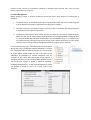
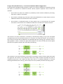
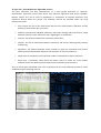
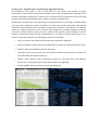
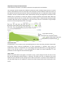
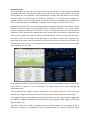
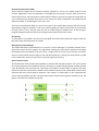
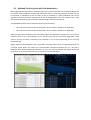
LiquidSonics
Reverberate
Convolution Reverb for Mac and PC
User Guide
Applies to Reverberate v1.915 (and above)
Liquid Sonics' Reverberate is a highly efficient hybrid convolution reverb audio processor offering
true zero-latency operation. Reverberate is able to provide a richer and more dynamic sounding
reverb from impulse responses by optionally modulating an amalgamation of two IRs; this combined
with a modulating post-processing effects (an all-pass interpolator chorus and over-sampled
analogue prototype paragraphic equaliser) means a more lively sound than typically associated with
convolution reverbs. In addition to loading impulse responses from audio files Reverberate is able to
generate supplementary early reflections for additional control over a room’s sonic characteristics.
Table of Contents
1.
2.
Installation and Registration
3
Windows PC
Mac
Impulse Response Locations
3
3
3
General Usage
4
Processing Delay
Lost Files Management
4
5
2.1.
Impulse Response Editor and EQ Tabs
IR / EQ Bypass
IR Type
Notes on IR Processing Topology
Length and Reversal
Gain
Spatial Widening and Mono Collapse
Amplitude Envelope and Normalisation
Automation Note
Copy / Reset
IR Equaliser Tabs
6
6
6
7
11
11
11
12
12
12
13
2.2.
Sample and Preset Management
Browser
Presets
14
14
14
2.3.
Mixer Tab
LFO
IR1 and IR2
IR Balance (Pan) and Final Mix
IR Chaining
Mono/Stereo Output Mixing
Stereo Channel Invert
16
16
16
17
17
17
17
2.4.
Post Equaliser Tab
Level, Frequency and Type
Modulation
18
18
18
2.5.
SplitMod Tab (Early/Late Pitch Modulation)
19
2.6.
All-Pass Interpolator Chorus Tab
20
2.7.
Stereo Modulated Delay Tab
21
2.8.
Settings Tab
22
Appendix A: Automation Parameter Names
25
1. Installation and Registration
To install Reverberate an Intel Mac or Windows VST/RTAS DAW PC is required. It is recommended to
install the plug-in on at least a Pentium 4 2.4GHz PC with 512MB memory. Installation and
registration are different under Mac and PC.
Windows PC
The install process will request a number of file locations, your license key file and the type of plug-in
you wish to install (VST for most hosts or RTAS/AAX for Pro-Tools). Typically Windows VST plug-ins
are installed in c:\Program Files\Steinberg\Vstplugins and this folder location should be selected
unless another location is used on the target system.
Special note for 64-bit VST installers: During the installation procedure you will be asked if you wish
to install Reverberate 64-bit using the same plug-in as Reverberate 32-bit.
•
For new users it is recommended that you use the same ID.
•
For users with projects in 32-bit hosts upgrading to 64-bit hosts and installing Reverberate
64-bit it is recommended to use the same ID as the host should then use Reverberate 64-bit
with your Reverberate 32-bit presets in your existing projects/songs.
•
For users with projects/songs made in Reverberate 64-bit 1.600 and below this is not
recommended as the host will no longer be able to locate Reverberate 64-bit.
Whilst it is possible to install Reverberate 32-bit and Reverberate 64-bit at the same time, where the
same plug-in ID option is selected with Reverberate 64-bit it is recommended that only Reverberate
64-bit is installed (i.e. Reverberate 32-bit should not be installed to avoid conflicts).
Mac
To install the plug-in on Mac, simply run the installer and select your local disk. The plug-in provides
32-bit and 64-bit versions in the same binary packages for VST, AU and AAX (the 64-bit version is
loaded automatically in 64-bit hosts) and a 32-bit binary for RTAS. Your license file is selected after
the installation process – open the plug-in and click the LiquidSonics logo, then click ‘License’ and
then select your license file from a location on disk.
Impulse Response Locations
The impulse responses included with Reverberate are installed into a default folder by the installer.
If you wish to manually move these to an alternative location to fit with other impulse responses in
your system it is recommended to set up a lost files directory for this (see general usage, lost files
management). Do not move the banks files (.fxb files).
2. General Usage
The plug-in is split into the following areas:
•
Impulse Response Editing Tab (x2) composed of three sub-tabs
o
Impulse responses from files (Wav, WIR, Aiff, SDIR, Flac)
o
Early reflections generator
o
Synthetic noise tail generator
•
Impulse Response EQ Tab (x2)
•
Impulse Response Mix Tab
•
SplitMod (x2, IR1/IR2) Tab
•
Chorus (x3, master and IR1/IR2) Tab
•
Stereo Modulated Delay (x3, master and IR1/IR2) Tab
•
Post Filter with Modulation Tab
•
Settings Tab
•
Sample Browser (including lost file management)
•
Presets Browser
The IR1 and IR2 tabs control the impulse responses to be used for the convolution reverb. Each
impulse response also has a dedicated filter tab which is applied as an offline process. The mix tab
specifies how the impulse responses are panned and mixed for output. The EQ and Chorus are post
effects that are applied to the convolved data from IR1 and IR2 in real-time.
When processing by the tab is active a subtle illumination behind the tab indicates activity. For
instance if one of the chorus modules is active in a preset this is indicated by a green hue above the
chorus tab. For the mixer tab, any setting that modulates or pans the audio causes the illumination
to show. This allows the user to quickly select presets with or without modulation, or to indicate
where a delay, chorus or modulation effect may be coming from.
Processing Delay
On the settings tab is a pull down to change the processing delay associated with the convolution
engine. This can be selected from a range of values and applies to all audio processes. Selecting a
higher delay typically reduces CPU load. Much effort has gone into optimising the plug-in for
efficient operation at zero delay and on a modern processor picking a higher blocking size may be
unnecessary.
It should be possible to use the plug-in at zero delay in any host regardless of block size and
whatever internal scheme is used to provide the plug-in with samples. Some hosts provide non-
powers of two, uneven or inconsistent numbers of samples across process calls; none of these
factors should affect zero latency.
Lost Files Management
When loading a preset, if impulse responses cannot be found, three means of locating files is
provided:
1. If a match cannot automatically be found via the methods below, the user is asked to specify
a file (in AAX the GUI must be opened for this selection to happen).
2. Favourite locations are searched if a file is missing on disk at load-time. Specifying favourites
is documented in the presets tab section.
3. The Browser Tab's options menu allows the user to select recursive search folder locations.
When files are lost, all folders within these locations are investigated when looking for files.
It is recommended that high-level locations with a lot of subfolders (e.g. c:\ or /Volumes) are
not selected as they will take a long time to search. A file's folder must match to count as the
same file, this is so that similarly named files in different folders are not selected.
In the example to the right, Small Room.wav would be lost if
My IRs were to be renamed to Impulse Responses or moved
into a different folder or disk. Setting this as a search folder
as shown below would enable the file to be found as all
subfolders of subfolders in Impulse Responses will be
analysed. A file called Small Room.wav within Rooms 2
would not be found as the enclosing folder (Rooms 1) must
also match (the version in Rooms 1 would be selected).
Changing Manufacturer 1 to My Fave Manufacturer would
not prevent a match as this is at a lower level in the
structure.
2.1. Impulse Response Editor and EQ Tabs
The impulse response tabs are the first encountered and each allows one or two stereo impulse
response to be loaded. Processing of each impulse response is done in parallel whilst providing a set
of independent controls for each.
IR / EQ Bypass
The impulse response and filter tabs have a bypass switch to enable processing of the IR and/or EQ
within the current tab. The grey/green power icon to the top right hand edge of the screen enables
or disables each component.
IR Type
The type control determines whether a file or bespoke impulse response is to be used for IR1 and/or
IR2.
IR Type: File – Loading Impulse Responses
The impulse response is loaded using the eject button next to the impulse response name (an
upwards pointing triangle), by selecting a file in the browser tab or by dropping a file from an
Explorer or Finder window into the IR visualisation area.
Mono, stereo and 4-channel IR files can be loaded. The parallel and mono-stereo topology modes
will only use the first two channels of a 4-channel file. In true stereo topology mode selecting the
same 4-channel file for IRx-A and IRx-B will load channels 1 and 2 into the IRx-A stereo pair and 3 and
4 into the IRx-B stereo pair.
The left and right spinner arrows provide the ability to rapidly move between files in the current
directory. When true stereo files are used and the auto pairing mode is active (see the settings tab)
the eject and arrows for IR1-A and IR2-A attempt to automatically load an appropriate file into the
IR1-B and IR2-B file containers based on the recognition of the presence of L, R, Left and Right (case
insensitive) in the file names.
Notes on IR Processing Topology
Three topologies for convolution are provided for each of the IR1 and IR2 containers:
1. Parallel Stereo: The left input channel is convolved with the left impulse response file
channel and the right input channel is convolved with the right impulse response file
channel. This is the typical configuration for stereo convolution reverbs when used with
stereo impulse responses, although when input audio is panned left or right, using ‘Mono to
Stereo’ may provide more intuitive results.
2. True Stereo: The left input channel is convolved with the left and right impulse response file
channels from IR1-A and the right input channel is convolved with the left and right impulse
response file channel from IR1-B. The two output convolutions’ respective left and right
components are then summed into a single stereo output. This configuration is necessary to
take full advantage of true stereo impulse responses. True stereo impulse responses are
required to be provided as two separate stereo files and loaded into IR1-A and IR1-B (or IR2A and IR2-B). This configuration is typically found in high-end algorithmic reverbs.
3. Mono to Stereo: The left and right input channels are mixed to mono and then
independently convolved with the left and right impulse response file channels. When using
a single stereo impulse response file, this is useful when input audio is panned hard left or
right; this configuration is often encountered in low/medium-end stereo algorithmic
reverbs.
IR Type: File (Parallel Stereo) – True Stereo Simulation Mode Configuration
In parallel stereo topology mode the option to select a true stereo simulation is provided increasing
the depth of character for standard 2-channel (stereo) impulse responses. Three modes are
available:
•
Sim-TS Off: The stereo IR is loaded as provided by the file without additional processing.
Only IRx-A is used for convolution.
•
Sim-TS Clear: A delayed copy of the IR is used as described below to create distinct and clear
additional reflections in the IRx-B true stereo convolver.
•
Sim-TS Dense: A windowed section of stereo white noise is convolved with the original
stereo IR to create a dense set of additional reflections in the IRx-B true stereo convolver.
‘Sim-TS Clear’ true stereo simulation is achieved by automatically loading a copy of the enveloped
and EQed stereo IR into the IRx-B container as if it were a true stereo IR file pair. The second IR is
then channel inverted and has additional user definable high pass filtering, gain reduction and predelay applied in order to create the typical effect heard in true stereo IR file pairs where signals
bleed into the opposite channel with some delay and filtering.
‘Sim-TS Dense’ true stereo simulation is achieved by convolving a section of stereo white noise with
the original IR. This creates a set of reflections which can be used to thicken and widen the sound of
traditional stereo IRs. In this mode the delay time refers to ¼ predelay followed by ¾ linearly
decaying windowed white noise (e.g. 40 ms delay has a 10 ms predelay and 30 ms decaying noise).
IR Type: ER – Early Reflections Algorithm Control
The early reflections and filter characteristics of a room greatly determine its character.
Reverberate’s proprietary virtual point source early reflection algorithms (Hall, Room, Chamber,
Basilica, Canyon etc) can be used to supplement or compliment an impulse response’s early
reflections directly within the plug-in. The following controls are provided within the early
reflections module:
•
Size: Controls the size of the model space and hence the time between reflections and the
quantity of attenuation due to air losses.
•
Diffusion: Controls how individual reflections react when meeting walls and surfaces. A high
diffusion quantity creates reflections with a high degree of randomness.
•
Distance: The distance between the transmitter and receiver.
•
Position: The side to side offset between transmitter and receiver affecting wall proximity
and panning.
•
Separation: The distance between stereo channels for both the transmitter and receiver
affecting the perceived width and phase characteristics of the early reflections.
•
Depth: Sets the complexity of the reflection model. Low depths have fewer reflections.
•
Room type: A pull-down menu below the Depth control to switch the room models.
Different rooms have different physical dimensions and filtering characteristics.
Once an IR has been established from a file or generated by the early reflections module it can be
modified using the following controls.
IR Type: Tail – Synthetic Noise Tail Generator Algorithm Control
Late reflections, also known as tails, provide much of the fullness and richness of longer
environments and the sense of space within smaller rooms. As tens of thousands of reflections from
multiple walls begin to merge into a cohesive sea of reverb the sonic characteristics of the tails tend
towards a dense spectrally shaped sound, similar in character to filtered noise.
Reverberate’s tails generator takes advantage of this phenomenon by providing a seeded random
noise generation algorithm capable of diffusion to mimic the gradual progression from defined
reflections to dense reverb tails. It is possible to create early reflections, late reflections or complete
reverb IRs using this generator. Once an IR has been designed the standard shaping and filtering
tools can be used to further refine the sound. Synthetic tails typically require filtering in order to
provide a natural sound which can be provided based on a number of room models using the tint
control or using the IRxEQ tab. The following parameters are available:
•
Decay: Provides a base length for the seeded noise generation algorithm.
•
Room Tint Model: Applies a base room equalisation (or white, for unfiltered synthetic noise).
•
Diffusion: Mimics the diffusion effect of real rooms.
•
Converge: Controls the speed at which the reflections diffuse and converge into a dense tail
from individually identifiable reflections.
•
Variant: Yields different sonic characteristics based on the same decay and diffusion
parameters by manipulating the starting value (seed) of the algorithm.
•
Diffusion Model: Affects the density and timing of diffusion.
Length and Reversal
Once loaded, the IR can be lengthened, shortened and stretched using the length controls. The IR
can be reversed using the arrows icon between the Start and End length controls.
Gain
A replica of the mixer’s gain dials are present on the IR1 and IR2 tabs for convenience during IR
editing and auditioning. Level meters and additional controls for panning and mix modulation are
accessed via the mixer.
Spatial Widening and Mono Collapse
The stereo width of the impulse response can be widened in stereo or collapsed to mono by varying
degrees. The widener is activated by using values greater than 100%; the mono collapse mode is
active between 0%-100% where 0% is fully mono; 100% represents the original signal.
The stereo widener works by inverting the phase of a delayed (7 ms) copy of each channel and
mixing it with the opposing channel. The inversion and opposing channel mix stage creates a
traditional widening effect and the delay reduces the impact of any subsequent mono-mix phases.
Wideners without a delay phase may cause any widened signals to null if passed through a mono
mix stage.
Note that processing works on the IR and not the signal chain, so to arrive at a fully mono output the
mono-to-stereo topology mode would be necessary. This is because processing the same IR in L and
R channels (i.e. a stereo IR collapsed to a mono IR) with parallel stereo mode retains all stereo width
present in the input - processing would sound more like a mono output due to the loss of width in
the IR, but not fully mono due to the retained width in the audio input. Alternatively post-process
mono mode could be set in the mixer view topology by clicking on the double/single circle imagery.
Amplitude Envelope and Normalisation
A normalisation parameter is provided to maximise the amplitude of the loaded IR.
The envelope controls provide the traditional synthesizer-style envelope shape controls to control
attack, hold and decay of the IR. The shape of the envelopes can be modified to affect the nature of
the speed of attack, decay and release. Versions of Reverberate prior to v1.403 used a linear shaped
envelope. Versions v1.403 and above allow exponentially decaying and logarithmic envelopes to be
defined with a parameter to control the degree of shaping applied (a horizontal slider below the
circular dials). Reverb tails may sound more natural when using an exponentially decaying shaped
envelope. Note that the plot is logarithmic in the vertical axis; on such a scale linear or log envelope
lines are curved and exponential lines are straight.
Log shaped envelope
Default linear shaped envelope
( or when shape slider is fully left)
Exponentially shaped envelope
Automation Note
All parameters in this section can be controlled by/from the host and obey parameter automation
instructions, hence real-time modification of these parameters is possible. Since many IR
modifications require re-computation for each change requested (denoted by an orange egg timer
shown in the top left corner) it is not recommended to apply host based modulation to such
parameters as CPU usage will be considerably higher.
Copy / Reset
Next to the power button (top right) is an option to copy / push settings from IR1 into IR2 or from
IR2 into IR1 (depending which IR Editor is selected). This allows the user to configure one IR and
duplicate all (or elements of) the settings into the other IR container. A number of reset facilities are
also provided along with the capability to swap IR1 and IR2 settings (useful when chaining IRs in the
mixer).
IR Equaliser Tabs
The associated IR EQ filter tabs for each impulse response provide a 5-band twice-oversampled
paragraphic EQ which is applied to the impulse response(s) in IR1 and IR2. The frequency and gain of
each EQ band can be modulated in time independently to apply swept EQ effects to the impulse
responses. When the final frequency and final gain parameters are set fully left no modulation is
applied, otherwise the EQ settings applied to the static IR will be modulated linearly between the
start to end times chosen. No modulation is applied if the end time is less than the start time.
Modulation of the EQ can be useful for applying subtle low pass filtering where the frequency cut-off
reduces over time to mimic the natural high frequency roll-off in real spaces, or for more creative
purposes. Frequency modulation can be set to a linear or exponential time base using the button
between the Start and End titles. Moving filters often sound more natural with an exponential time
base as lower frequencies are more pronounced. Gain modulation can be set to linear or half-cosine.
The view control sets the position of the EQ display in time. When set fully left it represents the
initial state of the EQ and fully right shows the final state of the EQ. The output of the IR EQ is not
affected by the view control, it is provided purely for user convenience to help visualise the effect
the modulation has over time.
Each frequency band has a full controls tab and there is also a consolidated controls tab where the
start position of bands 1-5 can be controlled in a single location for a more traditional EQ
manipulation view.
The consolidated view contains controls marked with a note button that can be used to set the
frequency to a range of presets from A0 to G#8 providing a very musical approach to equalisation.
The EQ graph handles can be dragged to change gain and frequency, and right clicked to toggle them
to enabled or disabled. Holding the keyboard ALT key and clicking a handle toggles the EQ type
(peak, low pass, etc).
The sheen control can be used to add high-frequency presence absent from the original IR. This is
achieved by mixing in an additional IR with an approximately flat frequency response whose
amplitude curve has been shaped to closely match that of the original IR. When IR normalisation is
enabled (as is typically the case) this can cause the amplitude of the original IR (which would
typically be more bass heavy than the sheen IR) to be reduced accentuating the effect.
2.2. Sample and Preset Management
Reverberate includes a browser that is always visible for locating either presets or IR sample files on
disk to load into IR1 or IR2. The browser mode is changed by clicking the IR Browser or Presets lower
tab headers.
Browser
Clicking a file loads a file into the currently active IR1a or IR2a slot (depending on the open tab).
Clicking the grey/green radio buttons loads a file into a specific file slot regardless of the open tab.
Use of the radio buttons means IR files can be changed in any of the IR1a/IR1b and IR2a/IR2b slots
regardless of the currently selected tab. This is particularly useful when the IR Mixer tab is open as
files can be auditioned and the mix gain/pan modified without the need to move between tabs
accelerating workflow.
A favourites menu is provided from which the user can focus the browser on any location where an
active IR file currently resides, select the local file system disks/drives or manage favourite location
presets.
The file filter text box allows the user to filter for files (but not directories) containing a plain-text
phrase such as plate, hall or aiff. Some hosts are subject to the caveat discussed in the next section.
Presets
The preset browser provides a mechanism to select and manipulate the 48 presets within a
Reverberate bank. Clicking a preset name selects it, and the name can be edited by clicking the italic
copy of the preset name above all the other presets and typing in the box (see caveat below
regarding some OS X hosts).
The preset tab is hidden by default in AAX as presets are provided in Pro Tools' native preset format.
The presets tab can be shown by selecting this in the settings tab. Within this tab is an option to
convert Reverberate presets into Pro Tools TFX preset files.
A number of factory preset banks are available from the Saved Banks button to the right of the
preset tab, and the user is able to select up to 10 bank (.fxb file) favourites for future recall.
Further capabilities are available within the load/save menu:
Load/Save: Current Preset:
•
Copy: Copy the current preset to an internal clipboard.
•
Paste: Paste the preset in the internal clipboard into the currently selected preset.
•
Clear: Wipe the current preset applying an empty preset state.
•
Swap with: Swap the positions of the current preset and another preset (to be selected in
the sub-menu).
Load/Save: Current Bank of Presets:
•
Load FXB Bank of Presets: Allows the user to select an FXB preset file from disk.
•
Save Presets as FXB Bank: Saves the current 48 presets in a new FXB bank to be selected by
the user.
•
Recent: Contains a list of recently loaded or saved FXB banks. The list can be edited by
clearing all entries, or removing individual items. Any FXB files at start-up found to be
missing on disk are automatically (and permanently) removed from the recent bank files list.
•
Clear All Presets in Bank: Wipe all memory resident presets clean to the empty preset state.
•
Create Bank of Presets From Current Preset: Using the current preset as a template, create a
bank of presets incrementing the IR for each preset from the current directory. Selecting this
option on preset 10 will only change presets 10 and above, this is useful when creating
presets from files in multiple directories.
Load/Save: Bank Initialisation Options: A number of choices are available for the initial presets that
will be used when the plug-in is loaded.
•
Initialise as Factory Defaults: The factory defaults will be loaded.
•
Initialise as Empty Preset: All presets will be loaded as empty presets ready for use with new
configurations.
•
Initialise with User Defined Bank: Uses the file selected by ‘Choose User Defined Bank File’.
Clicking this menu item displays what file will be used in a message box.
•
Choose User Defined Bank File: Opens a file selection dialog so the user can pick a default
file to use with the ‘Init as User Bank’ option.
Notes: Prior to v1.400 of Reverberate, the 48 preset slots were managed by the host. Since host
support for preset banks is variable (AU hosts in particular) preset management has been taken
within the plug-in such that a consistent bank management experience is available to all users. It is
advised to manage presets within Reverberate where possible as many hosts are unable to maintain
consistency when users are manipulating preset names within the plug-in. Many plug-ins without a
VST bank heritage only provide a single preset per bank avoiding this complication, but this approach
cannot be followed to ensure backwards compatibility with presets and banks embedded existing
songs.
Caveat: In OS X, preset naming is not possible in Live 8 due to GUI compatibility issues; it is
recommended to use the VST and re-name presets via the host and manage all other aspects of
presets and banks within Reverberate. LiquidSonics is working with the vendors of these hosts to
arrive at suitable solution.
2.3. Mixer Tab
The mixer tab provides the ability to set the levels of impulse responses and cross-fade between
them. VU meters are provided to give an indication of signal level.
LFO
The LFO controls the speed of modulation of all the controls featuring modulation on the mixer tab.
A control for applying the panning and mix modulation before or after the IR convolution processes
is provided.
IR1 and IR2
Independent gain and pan controls are provided for both IR1 and IR2. The Pan Mod control allows
the panning to be modulated using the LFO. The phase of the modulation allows the user to
independently control the position of the panning of the impulse responses relative to each other.
For example if the pan of IR1 is centre, and a fully modulated pan of IR1 is currently dragging the
panning hard left, replicating these settings on IR2 with a pan of 180 degrees will result in a pan of
hard right at the same instant. This allows the user to produce effects where the panning of one IR
follows or opposes the panning of another.
IR Balance (Pan) and Final Mix
These sections enables the mix between impulse responses 1 and 2 to be mixed relative to one
another. Modulation of the mix parameter is provided with the LFO (the current value of the mix is
shown below mod). The Flat Balance vs Raised Centre balance controls the shape of the IR1/IR2 mix
curve. Raised Centre provides some boost to the central mix when multiple IRs are loaded and Flat
Balance provides an unbiased gain cross-over curve.
The final mix parameters allow one final trim of gain to be made before mixing back with the dry
signal (the dry signal is delayed if a non-zero processing delay has been selected for the convolution
to keep audio in sync). The gain and mix can be locked using the padlock icon so that during a
program change the gain and mix do not change from the previous preset’s value.
IR Chaining
A chain option is provided in the final mix and signal flow areas which feeds the output of IR1 into
IR2 rather than processing them in parallel.
Mono/Stereo Output Mixing
The default behaviour of Reverberate is to process in stereo although it is possible to down-mix to
mono from stereo at three stages in the signal flow. Clicking the mono/stereo symbol on the signal
flow diagram (two interlinked circles for stereo, a single circle for mono) next to the IR1 or IR2 lines
mixes to mono before the pan stages of IR1 and IR2 respectively. Clicking the mono/stereo symbol
next to ‘Audio Out’ mixes to mono as the very final stage of processing.
Stereo Channel Invert
The Reverberate mixer provides the capability to swap the left and right channels. This can be useful
for creative purposes when additional space is desired. For example configuring IR1 and IR2 with the
same IR file where the second IR has a pre-delay of 20-100ms / 0.020-0.100s, is high plus low pass
filtered and has the L/R channels inverted creates additional space in the reverb space similar to that
achieved with true stereo impulse responses. This achieves a similar effect to the simulated true
stereo mode provided in the IR1 and IR2 parallel stereo modes but has greater flexibility as the full
gamut of controls are available for the IRs.
2.4. Post Equaliser Tab
Traditionally convolution reverbs provide an FIR filter for their sound modification needs. Whilst FIR
filters are linear phase and provide excellent results, they typically cannot provide modulation
capabilities as the filter needs a great deal of re-computation every time parameters change. For this
reason an oversampled IIR filter using 5-band analogue prototypes has been provided such that the
filter can be modulated, providing opportunities for a more dynamic sound.
The EQ graph handles can be dragged to change gain and frequency, and right clicked to toggle them
to enabled or disabled. The handle is shown at the midpoint of any gain and frequency modulation.
The filter is provided as a master effect and affects IR1 and IR2 but does not colour the dry path.
Level, Frequency and Type
Each filter can be controlled by gain and frequency. The filter types available depend on the filter
number.
-
Bands 1 and 2 provide low shelf, low cut and peak types.
-
Band 3 provides peak type.
-
Bands 4 and 5 provide high shelf, high cut and peak types.
Modulation
Two LFOs are provided for modulation purposes and can be used by any of the five filter bands. LFO1
is tied to gain and LFO2 to frequency. A phase control is provided on all bands such that the phase
(position in the LFO) of the modulation can be set independently for each band.
For example, by setting up two peak filters both using frequency modulation it is possible to get the
peaks to travel up and down with each other using the same phase, or travelling towards then apart
from each other using 180 degrees phase. As the filters update with respect to the modulation they
are shown in their instantaneous modulated state in the visualisation window as it refreshes itself.
2.5. SplitMod Tab (Early/Late Split Pitch Modulation)
Many high-end reverb processors modulate their early and late reflections to provide a dynamic and
rich sound. Since modulation of individual reflections within a pre-existing impulse response cannot
be achieved, a simulation of the net effect of this is provided as a pitch modulator that can be
applied to the early and late components of the IR independently. This can provide some of the
characteristic thickening and modulation desired in high-end reverb processors.
Two SplitMod modules are provided and are arranged as follows:
•
IR1: Connected to the outputs of IR1 (before the mix of IR1-A and IR1-B, if applicable).
•
IR2: Connected to the outputs of IR2 (before the mix of IR2-A and IR2-B, if applicable).
When using the pitch modulators the CPU load is higher as independent convolutions are running in
parallel as well as up to 4 modulators per IR. The IR is split into two convolvers depending on the
'split at' control, and then a separate pitch modulator is run on each depending on the rate and
depth selected.
Higher values of rate and depth cause a spin effect, and lower values more of a wandering effect (for
a natural sound lower rate values are recommended somewhere between 0.2 to 1 Hz with a
moderate delay depth somewhere between 1 to 2 ms). The rates and depths are slightly altered for
each stereo or true stereo channel to increase the perceived modulation.
2.6. All-Pass Interpolator Chorus Tab
In addition to the SplitMod function which modulates the IRs, a standard chorus is provided for
additional thickness. Three chorus modules are provided and are arranged as follows:
•
Post: Connected in series after mix of IR1 and IR2.
•
IR1: Connected to the outputs of IR1 (after the mix of IR1-A and IR1-B, if applicable).
•
IR2: Connected to the outputs of IR2 (after the mix of IR2-A and IR2-B, if applicable).
Many chorus effects use linear interpolators; these can sometimes introduce aliasing or other types
of distortion into the signal path so here an all-pass interpolator is used. These are more
computationally expensive but tend to sound better than using standard linear interpolation.
The traditional chorus controls are provided where a delay line of a certain length is modulated by a
given amount at a given rate. Additional controls are provided to control feedback (from a static
point half-way through the delay line) and a width control to control the stereo spread of the effect.
The Copy/Reset button provides a facility to reset individual elements of the chorus and to copy
setting to an internal clipboard. Once a setting has been copied to the internal clipboard from the
Post, IR1 or IR2 chorus modules it can be pasted to any of the Post, IR1 or IR2 chorus modules in
order to facilitate simple duplication of settings.
2.7. Stereo Modulated Delay Tab
Since a reverb effect is fundamentally a very long delay line with millions of taps simulating
reflections upon reflections in a room, many high end reverbs provide tempo delays as additional
effects to add a sense of rhythm to the reverb. Ranging from the almost imperceptible to bold and
striking, the use of delays can add real depth and character to a reverb.
To bring additional life to the delay, the analogue nature of tape delays (where the delay time is not
absolutely constant) can be recreated within Reverberate via two independently controllable delays
with delay tap line modulation and rate control (see controls mod and rate). The delays in
Reverberate can also be used to create ping-pong type effects using the cross-feed controls (R-Feed
/ L-Feed).
The input to the left and right delay lines can be turned on and off using the green radio buttons. If
one delay input is on and the other input is off, the cross-feed control can still be used to send audio
into the left or right unit without an active input. For example if the L Input is on and R Input is off,
using the R-Feed control on the left delay channel will input audio into the right delay unit.
The stereo delay is completely bypassed when both of these input buttons is turned off.
Three stereo delay modules are provided and are arranged as follows:
•
Post: Connected in series after mix of IR1 and IR2.
•
IR1: Connected to the outputs of IR1 (after the mix of IR1-A and IR1-B, if applicable).
•
IR2: Connected to the outputs of IR2 (after the mix of IR2-A and IR2-B, if applicable).
2.8. Settings Tab
A number of user settings are provided (selections are saved in the registry for the current user) and
apply to all instances of the plug-in. Reloading is typically necessary to propagate settings to all
instances.
Latency: The latency setting provides a means to set the delay associated with the plug-in. Longer
delays increase processing efficiency. A re-start of the plug-in is required to change latency.
Default Path: The default IR path controls how the eject buttons operate when selecting impulse
responses. The following options are available:
•
Most Recent: This passes responsibility for setting the initial location of the open box to the
operating system; it chooses the most recent location of a file-open dialog box if one is
available.
•
Current IR: The current location of the impulse response in IR1 or IR2 is used (depending
which eject button is pressed).
•
User Default: Depending on the location set with the ‘Set Default’ option, this option can be
used to select a standard location for the starting directory of eject dialog boxes. This may
be useful where the user has all their impulse responses stored in a central location on disk
(e.g. d:\Productions\Samples\Impulse Responses) and wishes to begin navigating from this
location when clicking eject.
•
Set Default: Opens a directory selection dialog so the user can pick a default directory to use
with the ‘User Default’ option.
Default Wet Mix: The default mix level on plug-in start-up or manual preset bank loads can be
changed here:
•
Off (Insert): The wet lock is disabled. Presets are typically provided configured for insert
effects.
•
On (Send): When using a reverb as a send it is common to want all presets to be fully wet.
This setting will override any wet/dry data stored in the preset and save it to fully wet. This
can then be disabled in the plug-in if desired.
•
Bank Default: Whatever was saved in the bank regarding wet lock will be preserved on load.
Auto-Pair True Stereo IR: When in true stereo mode and auto pairing is selected, loading a true
impulse response of the format <name>Left.<extension> or <name>L.<extension> will result in the
auto pairing function seeking an appropriate file named <name>Right.<extension> or
<name>R.<extension> for paired loading (pairing is case insensitive). This is only active when loading
files into the IR1-A and IR2-A containers when using the eject or left/right spinner buttons.
The IR1-B/IR2-B controls do not automatically pair files to enable rapid auditioning of alternative
pairings for true stereo impulse responses.
•
Off: No paring is attempted when changing IRs.
•
Attempt Paring: When loading IRs an attempt will be made to pair the files based on file
name. If files are named using a scheme not recognised by the plug-in pairing algorithm, no
automated pairing will be evident.
Sample Rate Dependence: The sample rate of the host or audio device can affect the sound of a
convolution reverb. This setting allows the user to normalise the behaviour of reverberate in
different host sample rate environments.
•
Host Rate Independent: The sample rate setting of the host will not affect the gain or filter
behaviour of Reverberate. IRs will be scaled relative to the host sample rate to ensure that
the output convolution amplitude is equal regardless of the host or soundcard sample rate
setting, and filters are always limited to a maximum frequency of 22 kHz.
•
Host Rate Dependent: The sample rate of the host can affect the gain and filter settings of
Reverberate. IRs will be normalised with respect to their amplitude only. Running at
different host or soundcard sample rates will cause the convolution of IRs to result in
differing amplitudes. Filters are limited to the Nyquist of the host sample rate instead of
being fixed to 22 kHz. For example, running Reverberate in a host set to 88.2 kHz will result
in the convolved audio output being twice as loud as if set to 44.1 khz using the same IR. This
mode of operation is included for compatibility with Reverberate versions 1.240 and below.
•
Downsample if >48kHz: In order to conserve CPU, Reverberate can be set to run at half the
host sample rate when the host is running at sample rates greater than 48 kHz. Audio is
downsampled to half rate, processed, and then upsampled to reduce CPU consumption. For
example, 48 kHz runs at 48 kHz, 88.2 kHz runs at 44.1 kHz, 96 kHz runs at 48 kHz, 192 kHz
runs at 96 kHz.
Dials Mode: Sets the way the dials react to dragging the mouse.
•
Circular: Move the mouse in a circular manner to change value.
•
Relative Circular: Similar to circular, but moves relative to the current position.
•
Slider: Move the mouse up and down to change value. Holding SHIFT on the keyboard allows
for fine-grain control in this mode.
Midi-CC / Assignment x: Sets a Midi change control (CC) to be assigned to one of a selection common
of parameters (e.g. ADSHR envelope, post-EQ, chorus mix, IR1/2 mix, gain and pan). Be aware that
automation of parameters that cause an IR to be recomputed (such as the ADSHR envelope) will
momentarily place load on the CPU.
Once a Midi-CC number has been selected Midi data must be routed to Reverberate via features in
the host application in order for it to be received and acted upon (not all hosts provide this capability
but it has been successfully tested in Cubase and Live using both VST and AU).
•
Midi-CC: Provides a value in the range 0-127, Off or Auto. In Auto mode the next time
Reverberate receives any Midi-CC messages the number of the first CC received is selected
in the drop-down menu. This feature is sometimes referred to as Midi-Learn and is useful
when you do not have a list of CC controller numbers to hand and find it quicker to simply
turn a dial on a controller device and have the plug-in use this controller CC number.
•
Assignment: Links a value to a parameter, or select None to remove any CC/parameter links.
IR Visualisation: Enables and disables the facility to show individual channels on the IR view page.
•
Multiple: Shows selection toggles to enable the different channels of an IR to
be selected on the IR1 and IR2 tab views (shown right).
•
IRx-All only: combines all IR graphs into one (default view).
Colour Scheme: Changes the colours of the interface.
•
Soft green: Subtle greens based on the classic Reverberate interface.
•
Neon blue: Vibrant blues and blacks.
Appendix A: Automation Parameter Names
Master params
Master gain
Master mix
Master IR1 IR2 mix
Master IR1 IR2 mix mod
Master wet lock ignore
Master stereo mono
IR1-IR2 chain
Mix mod pre/post conv
Bank’s cur program select
IR1
IR1 toggle
IR1 topology
IR1 normalise
IR1 gain
IR1 balance
IR1 balance mod
IR1 balance mod phase
IR1 stereo mono
IR1 user resample factor
IR1 crop from start
IR1 crop from end
IR1 reverse
IR1 L/R channel reverse
IR1 ADSHR A
IR1 ADSHR D
IR1 ADSHR S
IR1 ADSHR H
IR1 ADSHR R
IR1 ADSHR A shape
IR1 ADSHR D shape
IR1 ADSHR R shape
IR1 ADSHR A shape inv
IR1 ADSHR D shape inv
IR1 ADSHR R shape inv
IR1 pre delay
IR1 Width
IR1 ER Size
IR1 ER Diffusion
IR1 ER Distance
IR1 ER Position
IR1 ER Separation
IR1 ER Depth
IR1 Tail Length
IR1 Tail Diffusion
IR1 Tail Variant
IR1 Tail Convergence
IR1 Sim-TS Toggle
Gain
ReverbMix1
IR1/2Mix
IRMixMod
WetLockIg
MasterSt
IRChain
MxModOrdr
Prog#Sel
IROnOff1
IRTplgy1
IRNorm1
IRGain1
IRBal1
IRBal1Md
IRBal1Ph
IR1St
Length1
CropStrt1
CropEnd1
IRRev1
IRXCha1
Attack1
Decay1
Sustain1
Hold1
Release1
Atk1Shp
Dec1Shp
Rel1Shp
Atk1ShpI
Dec1ShpI
Rel1ShpI
PreDelay1
IRWidth1
ERSize1
ERDiff1
ERDist1
ERPos1
ERSepr1
ERDpth1
TailLen1
TailDif1
TailVrn1
TailCnv1
STSTog1
LFOs
Master EQ LFO1
Master EQ LFO2
Master mix rate
LFO1Rate
LFO2Rate
LFO3Rate
IR2
IR2 toggle
IR2 topology
IR2 normalise
IR2 gain
IR2 balance
IR2 balance mod
IR2 balance mod phase
IR2 stereo mono
IR2 user resample factor
IR2 crop from start
IR2 crop from end
IR2 reverse
IR2 L/R Channel reverse
IR2 ADSHR A
IR2 ADSHR D
IR2 ADSHR S
IR2 ADSHR H
IR2 ADSHR R
IR2 ADSHR A shape
IR2 ADSHR D shape
IR2 ADSHR R shape
IR2 ADSHR A shape inv
IR2 ADSHR D shape inv
IR2 ADSHR R shape inv
IR2 pre delay
IR2 Width
IR2 ER Size
IR2 ER Diffusion
IR2 ER Distance
IR2 ER Position
IR2 ER Separation
IR2 ER Depth
IR2 Tail Length
IR2 Tail Diffusion
IR2 Tail Variant
IR2 Tail Convergence
IR2 Sim-TS Toggle
IROnOff2
IRTplgy2
IRNorm2
IRGain2
IRBal2
IRBal2Md
IRBal2Ph
IR2St
Length2
CropStrt2
CropEnd2
IRRev2
IRXCha2
Attack2
Decay2
Sustain2
Hold2
Release2
Atk2Shp
Dec2Shp
Rel2Shp
Atk2ShpI
Dec2ShpI
Rel2ShpI
PreDelay2
IRWidth2
ERSize2
ERDiff2
ERDist2
ERPos2
ERSepr2
ERDpth2
TailLen2
TailDif2
TailVrn2
TailCnv2
STSTog2
IR1 Sim-TS Gain
IR1 Sim-TS HPF freq
IR1 Sim-TS HPF toggle
IR1 Sim-TS Pre-Delay
IR1 filter
IR1 filter Master toggle
IR1 filter1 toggle
IR1 filter1 mode
IR1 filter1 freq
IR1 filter1 gain
IR1 filter1 q
IR1 filter2 toggle
IR1 filter2 mode
IR1 filter2 freq
IR1 filter2 gain
IR1 filter2 q
IR1 filter3 toggle
IR1 filter3 mode
IR1 filter3 freq
IR1 filter3 gain
IR1 filter3 q
IR1 filter4 toggle
IR1 filter4 mode
IR1 filter4 freq
IR1 filter4 gain
IR1 filter4 q
IR1 filter5 toggle
IR1 filter5 mode
IR1 filter5 freq
IR1 filter5 gain
IR1 filter5 q
IR1 filter1 freq mod to
IR1 filter1 freq start time
IR1 filter1 freq end time
IR1 filter1 gain mod to
IR1 filter1 gain start time
IR1 filter1 gain end time
IR1 filter2 freq mod to
IR1 filter2 freq start time
IR1 filter2 freq end time
IR1 filter2 gain mod to
IR1 filter2 gain start time
IR1 filter2 gain end time
IR1 filter3 freq mod to
IR1 filter3 freq start time
IR1 filter3 freq end time
IR1 filter3 gain mod to
IR1 filter3 gain start time
IR1 filter3 gain end time
STSGain1
STSFreq1
STSFrqT1
STSDly1
IR2 Sim-TS Gain
IR2 Sim-TS HPF freq
IR2 Sim-TS HPF toggle
IR2 Sim-TS Pre-Delay
STSGain2
STSFreq2
STSFrqT2
STSDly2
IR1filter
IR1filter1
IR1Mode1
IR1Freq1
IR1Gain1
IR1Q1
IR1filter2
IR1Mode2
IR1Freq2
IR1Gain2
IR1Q2
IR1filter3
IR1Mode3
IR1Freq3
IR1Gain3
IR1Q3
IR1filter4
IR1Mode4
IR1Freq4
IR1Gain4
IR1Q4
IR1filter5
IR1Mode5
IR1Freq5
IR1Gain5
IR1Q5
IR1Fq1to
IR1Fq1st
IR1Fq1en
IR1Gn1to
IR1Gn1st
IR1Gn1en
IR1Fq2to
IR1Fq2st
IR1Fq2en
IR1Gn2to
IR1Gn2st
IR1Gn2en
IR1Fq3to
IR1Fq3st
IR1Fq3en
IR1Gn3to
IR1Gn3st
IR1Gn3en
IR2 filter
IR2 filter Master toggle
IR2 filter1 toggle
IR2 filter1 mode
IR2 filter1 freq
IR2 filter1 gain
IR2 filter1 q
IR2 filter2 toggle
IR2 filter2 mode
IR2 filter2 freq
IR2 filter2 gain
IR2 filter2 q
IR2 filter3 toggle
IR2 filter3 mode
IR2 filter3 freq
IR2 filter3 gain
IR2 filter3 q
IR2 filter4 toggle
IR2 filter4 mode
IR2 filter4 freq
IR2 filter4 gain
IR2 filter4 q
IR2 filter5 toggle
IR2 filter5 mode
IR2 filter5 freq
IR2 filter5 gain
IR2 filter5 q
IR2 filter1 freq mod to
IR2 filter1 freq start time
IR2 filter1 freq end time
IR2 filter1 gain mod to
IR2 filter1 gain start time
IR2 filter1 gain end time
IR2 filter2 freq mod to
IR2 filter2 freq start time
IR2 filter2 freq end time
IR2 filter2 gain mod to
IR2 filter2 gain start time
IR2 filter2 gain end time
IR2 filter3 freq mod to
IR2 filter3 freq start time
IR2 filter3 freq end time
IR2 filter3 gain mod to
IR2 filter3 gain start time
IR2 filter3 gain end time
IR2filter
IR2filter1
IR2Mode1
IR2Freq1
IR2Gain1
IR2Q1
IR2filter2
IR2Mode2
IR2Freq2
IR2Gain2
IR2Q2
IR2filter3
IR2Mode3
IR2Freq3
IR2Gain3
IR2Q3
IR2filter4
IR2Mode4
IR2Freq4
IR2Gain4
IR2Q4
IR2filter5
IR2Mode5
IR2Freq5
IR2Gain5
IR2Q5
IR2Fq1to
IR2Fq1st
IR2Fq1en
IR2Gn1to
IR2Gn1st
IR2Gn1en
IR2Fq2to
IR2Fq2st
IR2Fq2en
IR2Gn2to
IR2Gn2st
IR2Gn2en
IR2Fq3to
IR2Fq3st
IR2Fq3en
IR2Gn3to
IR2Gn3st
IR2Gn3en
IR1 filter4 freq mod to
IR1 filter4 freq start time
IR1 filter4 freq end time
IR1 filter4 gain mod to
IR1 filter4 gain start time
IR1 filter4 gain end time
IR1 filter5 freq mod to
IR1 filter5 freq start time
IR1 filter5 freq end time
IR1 filter5 gain mod to
IR1 filter5 gain start time
IR1 filter5 gain end time
IR1 filter1 freq mod shape
IR1 filter2 freq mod shape
IR1 filter3 freq mod shape
IR1 filter4 freq mod shape
IR1 filter5 freq mod shape
Master filter
Filter Master toggle
Filter1 toggle
Filter1 mode
Filter1 freq
Filter1 freq mod
Filter1 freq mod phase
Filter1 gain
Filter1 gain mod
Filter1 gain mod phase
Filter1 q
Filter2 toggle
Filter2 mode
Filter2 freq
Filter2 freq mod
Filter2 freq mod phase
Filter2 gain
Filter2 gain mod
Filter2 gain mod phase
Filter2 q
Filter3 toggle
Filter3 mode
Filter3 freq
Filter3 freq mod
Filter3 freq mod phase
Filter3 gain
Filter3 gain mod
Filter3 gain mod phase
Filter3 q
Filter4 toggle
Filter4 mode
Filter4 freq
IR1Fq4to
IR1Fq4st
IR1Fq4en
IR1Gn4to
IR1Gn4st
IR1Gn4en
IR1Fq5to
IR1Fq5st
IR1Fq5en
IR1Gn5to
IR1Gn5st
IR1Gn5en
EQ1Frq1S
EQ1Frq2S
EQ1Frq3S
EQ1Frq4S
EQ1Frq5S
Filters
Filter#1
Mode #1
Freq #1
FrqMod#1
FrqMPh#1
Gain #1
GainM#1
GainMP#1
Q #1
Filter#2
Mode #2
Freq #2
FrqMod#2
FrqMPh#2
Gain #2
GainM#2
GainMP#2
Q #2
Filter#3
Mode #3
Freq #3
FrqMod#3
FrqMPh#3
Gain #3
GainM#3
GainMP#3
Q #3
Filter#4
Mode #4
Freq #4
IR2 filter4 freq mod to
IR2 filter4 freq start time
IR2 filter4 freq end time
IR2 filter4 gain mod to
IR2 filter4 gain start time
IR2 filter4 gain end time
IR2 filter5 freq mod to
IR2 filter5 freq start time
IR2 filter5 freq end time
IR2 filter5 gain mod to
IR2 filter5 gain start time
IR2 filter5 gain end time
IR2 filter1 freq mod shape
IR2 filter2 freq mod shape
IR2 filter3 freq mod shape
IR2 filter4 freq mod shape
IR2 filter5 freq mod shape
IR2Fq4to
IR2Fq4st
IR2Fq4en
IR2Gn4to
IR2Gn4st
IR2Gn4en
IR2Fq5to
IR2Fq5st
IR2Fq5en
IR2Gn5to
IR2Gn5st
IR2Gn5en
EQ2Frq1S
EQ2Frq2S
EQ2Frq3S
EQ2Frq4S
EQ2Frq5S
Chorus
Chorus Master feedback
Chorus Master width
Chorus Master dry
Chorus Master wet
Chorus Master delay ms
Chorus Master delay mod ms
Chorus Master delay mod rate hz
Chorus Master toggle
Chorus IR1 feedback
Chorus IR1 width
Chorus IR1 dry
Chorus IR1 wet
Chorus IR1 delay ms
Chorus IR1 delay mod ms
Chorus IR1 delay mod rate hz
Chorus IR1 toggle
Chorus IR2 feedback
Chorus IR2 width
Chorus IR2 dry
Chorus IR2 wet
Chorus IR2 delay ms
Chorus IR2 delay mod ms
Chorus IR2 delay mod rate hz
Chorus IR2 toggle
ChrMFdB
ChrMWdth
ChrMDry
ChrMWet
ChrMDly
ChrMDlMd
ChrMDlRt
ChrMTgle
Chr1FdB
Chr1Wdth
Chr1Dry
Chr1Wet
Chr1Dly
Chr1DlMd
Chr1DlRt
Chr1Tgle
Chr2FdB
Chr2Wdth
Chr2Dry
Chr2Wet
Chr2Dly
Chr2DlMd
Chr2DlRt
Chr2Tgle
Filter4 freq mod
Filter4 freq mod phase
Filter4 gain
Filter4 gain mod
Filter4 gain mod phase
Filter4 q
Filter5 toggle
Filter5 mode
Filter5 freq
Filter5 freq mod
Filter5 freq mod phase
Filter5 gain mod
Filter5 gain mod phase
Filter5 gain
Filter5 q
IR1 Delay
IR1 Delay Dry
IR1 Delay L Feedback
IR1 Delay L R-Feedback
IR1 Delay L Wet
IR1 Delay L Delay mod
IR1 Delay L Delay mod rate
IR1 Delay L Toggle
IR1 Delay R Feedback
IR1 Delay R L-Feedback
IR1 Delay R Wet
IR1 Delay R Delay mod
IR1 Delay R Delay mod rate
IR1 Delay R Toggle
IR1 Delay L Tempo lock
IR1 Delay R Tempo lock
IR1 SplitMod
IR1 Split Point
IR1 Section 1 Toggle
IR1 Section 1 Mod Rate
IR1 Section 1 Mod Depth
IR1 Section 2 Toggle
IR1 Section 2 Mod Rate
IR1 Section 2 Mod Depth
FrqMod#4
FrqMPh#4
Gain #4
GainM#4
GainMP#4
Q #4
Filter#5
Mode #5
Freq #5
FrqMod#5
FrqMPh#5
GainM#5
GainMP#5
Gain #5
Q #5
IR2 Delay
IR2 Delay Dry
IR2 Delay L Feedback
IR2 Delay L R-Feedback
IR2 Delay L Wet
IR2 Delay L Delay mod
IR2 Delay L Delay mod rate
IR2 Delay L Toggle
IR2 Delay R Feedback
IR2 Delay R L-Feedback
IR2 Delay R Wet
IR2 Delay R Delay mod
IR2 Delay R Delay mod rate
IR2 Delay R Toggle
IR2 Delay L Tempo lock
IR2 Delay R Tempo lock
Dly1LDry
Dly1LFdB
Dly1LFBO
Dly1LWet
Dly1LDlM
Dly1LDlR
Dly1LTgl
Dly1RFdB
Dly1RFBO
Dly1RWet
Dly1RDlM
Dly1RDlR
Dly1RTgl
Dly1-LkL
Dly1-LkR
Master Delay
Master Delay Dry
Master Delay L Feedback
Master Delay L R-Feedback
Master Delay L Wet
Master Delay L Delay mod
Master Delay L Delay mod rate
Master Delay L Toggle
Master Delay R Feedback
Master Delay R L-Feedback
Master Delay R Wet
Master Delay R Delay mod
Master Delay R Delay mod rate
Master Delay R Toggle
Master Delay L Tempo lock
Master Delay R Tempo lock
IR1SM-SP
IR1SM1Tg
IR1SM1MR
IR1SM1MD
IR1SM2Tg
IR1SM2MR
IR1SM2MD
IR2 SplitMod
IR2 Split Point
IR2 Section 1 Toggle
IR2 Section 1 Mod Rate
IR2 Section 1 Mod Depth
IR2 Section 2 Toggle
IR2 Section 2 Mod Rate
IR2 Section 2 Mod Depth
Dly2LDry
Dly2LFdB
Dly2LFBO
Dly2LWet
Dly2LDlM
Dly2LDlR
Dly2LTgl
Dly2RFdB
Dly2RFBO
Dly2RWet
Dly2RDlM
Dly2RDlR
Dly2RTgl
Dly2-LkL
Dly2-LkR
DlyMLDry
DlyMLFdB
DlyMLFBO
DlyMLWet
DlyMLDlM
DlyMLDlR
DlyMLTgl
DlyMRFdB
DlyMRFBO
DlyMRWet
DlyMRDlM
DlyMRDlR
DlyMRTgl
DlyM-LkL
DlyM-LkR
IR2SM-SP
IR2SM1Tg
IR2SM1MR
IR2SM1MD
IR2SM2Tg
IR2SM2MR
IR2SM2MD
Thanks to all our beta testers, those with great feature suggestions and various bug hunters including (but not limited to) Dax Liniere, Renan
Lau Blois, Jeff Pettit, Brent Randall, Christopher Brindley, Tatsuo Miyachi and Sean Costello. Special thanks to Michael Olsen of
PhonoXone and Seth Kingsley of VSTAU for their extensive contributions to the OS X port. Any grave injustices in the form of omissions
from this list should be directed to LiquidSonics support for a full apology!