1
Operator's
Manual
I:RRFTSMRN°
LAWN TRACTOR
7 Speed, Shift-on-the-Go
42" Deck
Model No. 247.28883
• Espanol,
P. 58
This product has a low emission engine which operates differently
from previously built engines. Before you start the engine, read and
understand this Operator's Manual.
Before
For answers
this product,
using this equipment,
to your questions
Call:
read this manual and follow
1-800-659-5917
all safety rules and operating
Craftsman Tractor Help Line
instructions.
about
7 am - 7 pm CT, Mon. - Sun.
Sears Brands Management Corporation,
Visit our website:
Hoffman Estates, IL 60179 U.S.A.
www.craftsman.com
FormNo.769-06501
(November
1,2010)
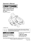
Warranty Statement ..........................................................
Safety Instructions ............................................................
Slope Gauge .....................................................................
Safety Labels ............. .......................................................
Assembly .........................................................................
Operation ........................................................................
Service and Maintenance
..............................................
CRAFTSMAN
2
3
8
9
10
12
18
Off-Season Storage ........................................................ 27
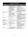
Troubleshooting .............................................................. 28
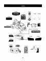
Labels ............................................................................. 29
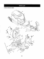
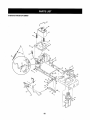
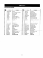
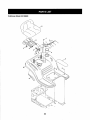
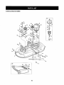
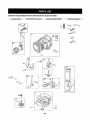
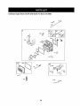
Parts List ......................................................................... 30
Espaffol............................................................................ 57
Service Numbers ............................................. Back Cover
TWO YEAR FULL WARRANTY
FORTWO YEARSfrom the dateof purchase,ifany non-expendablepartof thisriding equipmentfails dueto a defectin material orworkmanship, visitwww;craftsman.comor call1-800-659-5917 toarrangefor free in-homerepair.
Theframe and front axle willbe repairedfree of chargefor five years from the date of purchase if defective in matedal or workmanship.
In att cases, if repair proves impossible, the riding equipmentwill be replaced free of charge withthe same or an equivalentmodel.
The battery willbe replaced free of charge for 90 days from lhe date of purchase if defective in materialor workmanship(our testing proves that it
willnot hold a charge).
This warrantyis void if this product is ever used whileproviding commercial servicesor if rented to another person.
This warranty covers ONLYdefects in material and workmanship.Warrantycoverage does NOT include:
•
Expendableitemsthat can wearout from normal use withinthe warranty period, including but not limited to blades, spark plugs, air
cleaners,belts, andoil filters.
•
Standardmaintenanceservicing, oil changes, or tune-ups.
•
Tire replacementor repaircausedby punctures from outside objects,such as nails,thorns; stumps, or glass.
•
Tire or wheel replacement or repairresultingfrom normalwear, accident, or improperoperation or maintenance.
•
Repairsnecessarybecause of operator abuse, including but not limitedto damage caused by towing objects beyondthe capability of
the riding equipment,impacting objects that bend the frame or crankshaft, or over-speedingthe engine.
•
Repairsnecessarybecause of operator negligence, including but notlimited to, electrical and mechanical damage caused by improper
Storage,failure to use the proper grade and amount of engine oil, failure to keepthe deck clear of flammable debris, or failure to
maintainthe ridingequipmentaccording to the instructionscontained in the operator's manual.
•
Engine (fuel system) cleaning or repairs caused byfuel determined to be contaminated or oxidized (stale). tn general, fuel should be
used within30 days of its purchasedate.
•
Normal deteriorationand wearof the exterior finishes, or product label replacement.
Thiswarranty
givesyouspecificlegalrights,andyoumayalsohaveotherrightswhichvaryfromstateto state.
SearsBrandsManagement
Corporation,
HoffmanEstates,]L 60179
Model Number:
Engine Oil:
Fuel:
SAE 30
UnleadedGasoline
Spark Plug:
Champion®RC12YC
Engine:
Briggs & Stratton I/C®
© KCD FRLLC
Serial Number:
Dateof Purchase:
Recordthe model number,serial number,
and date of purchaseabove.
2
Thismachinewasbuiltto beoperatedaccordingtothesafeoperationpracticesin thismanual.As withanytypeof powerequipment,
carelessness
or erroron thepartoftheoperatorcanresultinserious
injury.Thismachineis capableofamputating
fingers,hands,toes
andfeet andthrowingdebris.Failuretoobservethefollowingsafety
instructions
couldresultin seriousinjuryor death.
Thissymbolpointsoutimportantsafetyinstructions
which,if not
followed,couldendangerthepersonalsafetyand/orpropertyof
yourselfand others.Readandfollowall instructions
in this manual
beforeattemptingtooperatethismachine.Failuretocomplywith
theseinstructionsmayresultin personalinjury.Whenyouseethis
symbol,HEEDITSWARNING!
CALIFORNIA
PROPOSITION
65
Your Responsibility--Restrict
theuseofthis powermachineto
persons
whoread,understand
andfollowthewarnings
andinstructionsin thismanual
andonthemachine,
EngineExhaust,someof its constituenls,
and certainvehicle
componentscontainor emitchemicals
knownto Stateof California
to causecancerandbirthdefectsor otherreproductive
harm.
Batteryposts,terminals,and relatedaccessories
contain]eadand
leadcompounds,chemicals
knowntotheStaleofCaliforniato
causecancerandreproductive
harm.Washhandsafter handling.
IIIIHIIIIIIIIIIIIIIIIIIIII
I II
GENERAL
,
•
•
•
•
•
SAVE THESE INSTRUCTIONS!
I
L I
OPERATION
Read,understand,
andfollowall instructions
on themachineand
in themanual(s)beforeattemptingtoassembleandoperate.
Keepthismanualin a safeplaceforfutureand regularreference
andfor orderingreplacement
parts.
Befamiliarwithall controlsandtheirproperoperation.Knowhow
tostopthemachineanddisengage
themquickly.
Neverallowchildrenunder14yearsold tooperatethis machine.
Children14yearsold andovershouldreadandunderstandthe
operationinstructionsandsafetyrulesin this manualandshould
be trainedand supervised
bya parent.
Neverallowadultstooperatethis machinewithoutproper
instruction.
Tohelpavoidbladecontactor a thrownobjectinjury,keep
bystanders,helpers,childrenandpetsat least75 feetfromthe
machinewhileitis inoperation.Stopmachineif anyoneenters
thearea.
Thoroughlyinspecttheareawheretheequipmentistobe used.
Removeall stones,sticks,wire,bones,toys,andotherforeign
objectswhichcouldbe pickedupandthrownbythe blade(s).
Thrownobjectscancauseseriouspersonal
injury.
Planyourmowingpatterntoavoiddischargeof materialtoward
roads,sidewalks,bystandersandthelike.Also,avoiddischargingmaterialagainsta wallor obstructionwhichmaycause
dischargedmaterialto ricochet
backtowardtheoperator.
3
•
Alwayswearsafety glasses or safety goggles during operation
and while performingan adjustment or repairto protect your eyes.
Thrown objectswhich ricochetcan causeserious injury to the
eyes.
,
Wear sturdy, rough-soledwork shoes and close-fitting slacksand
shirts. Loosefitting clothesand jewelry can be caught in movable
parts.Never operate this machinein bare feet or sandals.
•
Be aware of the mower and attachmentdischarge directionand
do not pointit at anyone. Do not operate lhe mower withoutthe
discharge cover or entire grass catcherin its proper place.
•
Donot put hands or feet near rotatingparts or under the cutting
deck. Contact with the blade(s) canamputate hands andfeet.
•
A missing or damageddischarge cover can cause bladecontact
or thrown object injuries.
•
Stop the blade(s) when crossing gravel drives,walks, or roads
and while not cutting grass.
•
Watch fortraffic when operating near or crossing roadways.This
machine is not intendedfor use on any public roadway.
•
Do not operate the machinewhile under the influence of alcohol
or drugs.
•
•
Mow only in daylightor good artificiallight.
Nevercarry passengers.
•
Disengageblade(s) beforeshifting into reverse. Back up slowly.
Always look down and behind beforeand while backing to avoid a
back-overaccident.
*
•
•
°
•
,
•
•
•
°
Slowdownbeforeturning.Operatethemachinesmoothly.Avoid
erraticoperationandexcessivespeed.
Disengageblade(s),setparkingbrake,stopengineandwaituntil
theblade(s)cometo a completestopbeforeremovinggrass
catcher,emptyinggrass,uncloggingchute,removinganygrassor
debris,or makinganyadjustments.
Neverleavea runningmachineunattended.
Alwaysturnoff
blade(s),setparkingbrake,stopengineandremovekey before
dismounting.
Useextracarewhenloadingor unloadingthemachineintoa
traileror truck.Thismachineshouldnotbedrivenupor down
ramp(s),becausethemachinecouldlip over,causingserious
personalinjury.Themachinemustbe pushedmanuallyon
ramp(s)toload or unloadproperly.
Mufflerandenginebecomehotandcancausea burn.Donot
touch.
Checkoverheadclearancescarefullybeforedrivingunderlow
hangingtreebranches,wires,dooropeningsetc.,wherethe
operatormaybestruckor pulledfromthemachine,whichcould
resultin seriousinjury.
Disengageall attachmentclutchesanddepressthebrakepedal
completelybeforeattemptingtostartengine.
Yourmachineis designedtocut normalresidentialgrassof a
heightno morethan10".Donotattemptto mowthroughunusually
tall,drygrass(e.g.,pasture)or pilesofdryleaves.Drygrassor
leavesmaycontacttheengineexhaustand/orbuildupon the
mowerdeckpresentinga potentialfirehazard.
Useonlyaccessoriesandattachmentsapprovedforthismachine
bythe machinemanufacturer.
Read,understand
andfollowall
instructions
providedwiththeapprovedaccessoryorattachment.
Fora listof approvedaccessories
and attachments,
call1-800659-5917.
Dataindicatesthat operators,age60yearsandabove,are
involvedin a largepercentageof ridingmower-related
injuries.
TheseoperatorsshouJdevaluatetheirabilityto operatetheriding
mowersafelyenoughto protectthemselvesandothersfrom
seriousinjury.
If situationsoccurwhicharenotcoveredinthis manual,usecare
andgoodjudgment.Contactt-800-659-5917
for information
and
assistance.
4
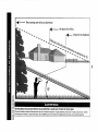
SLOPE OPERATION
Slopesarea majorfactorrelated
tolossofcontrol
and tip-over
accidents
whichcanresultinsevereinjuryordeath.All slopesrequire
extracaution,
ifyoucannotbackuptheslopeorifyoufeeluneasyon
it,do notmowit.
Foryoursafety,
usetheSlopeGuideincluded
as partofthismanual
tomeasureslopes
beforeoperating
thismachine
ona slopedorhilly
area.Iftheslopeisgreaterthant5 degreesasshownontheSlope
Guide,donotoperate
thismachineonthatareaorserious
injurycould
result.
Do:
o
Mow up and down slopes, notacross. Exercise extreme caution
whenchanging directionon slopes.
•
Watch for holes, ruts, bumps, rocks,or other hidden objects.
Uneventerrain could overturnthe machine.Tall grass can hide
obstacles.
*
Useslow speed. Choose a low enough speed setting so that
you willnot have to stop or shift whileon the slope. Tires may
lose tractionon slopes even thoughthe brakes are functioning
properly. Alwayskeep machinein gear when going down slopes
to take advantageof engine braking action.
•
Follow the manufacturer'srecommendationsfor wheel weights
or counterweightsto improvestability. For recommendations,
call
1-800-659-5917.
•
Use extra care withgrass catchersor other attachments. These
can change the stability of the machine.
•
Keep all movementon the slopes slow and gradual. Donot make
suddenchanges in speed or direction. Rapid engagementor
brakingcould cause the front of the machine to lift and rapidlyflip
over backwardswhich could cause serious injury.
*
Avoid startingor stopping on a slope. If tires lose traction,disengage the blade(s) and proceedslowly straightdown the slope.
Do Not:
•
Do not turn on slopes unless necessary; then, turn slowly and
gradually downhill, if possibEe,
•
Do not mow near drop-offs, ditches or embankments.The mower
could suddenly turn over ffa wheel is over the edge of a cliff,
ditch, or if an edge caves in.
•
Do not try to stabilize the machineby putting your foot on the
ground.
•
Do not use a grass catcheron steep slopes.
•
°
Do not mow on wet grass. Reducedtraction could cause sliding.
Do not attemptto coast downhill. Over-speedingmay causethe
operatorto lose control of the machine resultingin serious injury
or death.
•
Do not tow heavypull behind attachments(e.g. leaded dump cart,
lawnroller, etc.) on slopes greaterthan 5 degrees. When going
down hill, the extra weight tends to pushthe tractor and may
causeyou to loosecontrol (e.g. tractor may speed up, brakingand
steeringability are reduced,attachmentmay jack-knife and cause
tractor to overturn).
CHILDREN
SERVICE
Tragicaccidents can occur if the operator is not alert to the presence
of children. Children are often attracted to the machine andthe mowing
activity.They do not understandthe dangers. Neverassume that
children will remainwhere you last saw them,
Safe Handlingof Gasoline
•
•
•
•
•
•
.............................
•
Keep children out of the mowing area and in watchful care of a
responsibleadult other than the operator.
Be alert and turn machineoff if a child entersthe area,
Before and while backing, Fookbehind and down for small
chUdren,
Toavoid personal injury or property damage use extremecare in
handlinggasoline.Gasolineis extremelyflammable andthe vapors are
explosive.Serious personal iniury can occur whengasoline is spilled
on yourself or your clotheswhich can ignite. Washyour skin and
changeclothes immediately.
•
•
witha plastic liner.Alwaysplace containers on the ground away
from your vehicle beforefilling.
•
When practical, remove gas-poweredequipment from the truck
or trailer and refuel it on the ground. If this is not possible, then
refuelsuch equipment on a trailer with a portable container, rather
Use extreme care when approaching blind corners, doorways,
than from a gasoline dispenser nozzle.
shrubs,trees or otherobjects that may block your vision of a child
who may run into the machine.
,
Keep the nozzle in contact withthe rim of the fuel tank or
container opening at all times until fueiing is complete.Do not use
Toavoid back-overaccidents, always disengage the cutting
blade(s) beforeshifting into Reverse, If equipped, the "Reverse
a nozzle lock-open device.
-Caoti-on-Mode_-(bla-d-e+s-_p-e-rate-whiJ_m+a_hin-e-tPde-s_n-t_v_ts-e)
-....... +-- -E:<tih-g_|_
h-all-cig_t_ttes_-cig_T-pip_-8._-d
_th_u_e_
f
should not be used whenchildren or others are around.
ignition.
•
Neverfuel machine indoors.
Keepchildren awayfrom hot or running engines.They can suffer
burns from a hot muffler.
,
Neverremove gas cap or add fueI whilethe engine is hot or runNever carry children, evenwith the blade(s) shut off. They may
fail off and be seriouslyinjured or interferewith safe machine
operation.
•
Removekeywhen machineis unattendedto prevent unauthorized
operation.
Neverallow childrenunder 14 years of ageto operate this machine.
Children _4 and overshould read and understand the instructions and
safe operation practicesin this manual andon the machine and should
be trained and supervised by an adult.
o
ning.Allow engine to cool at least two minutes before refueling.
Neverover fill fuel tank. Filltank to no morethan _/2inchbelow
°
bottom of filler neck to allowspace for fuel expansion.
Replacegasoline cap and tighten securely.
•
If gasoline is spilled, wipe it off the engine and equipment. Move
machine to another area.Wait 5 minutes beforestarting the
engine.
•
To reducefire hazards, keepmachinefree of grass, leaves,or
other debris build-up. Clean up oil or fuel spillage and remove any
fuel soakeddebris.
°
Neverstore the machine or fuel container inside where there is an
•
open flame, spark or pilot light as on a water heater,space heater,
furnace, clothes dryer or othergas appliances.
Allow a machineto cool at least five minutes beforestoring.
TOWING
•
•
Useonly an approved gasoline container.
Neverfill containers inside a vehicle or on a truck or trailer bed
Tow only witha machinethat has a hitch designed for towing. Do
not attach towed equipmentexcept at the hitch point.
Follow the manufacturers recommendationfor weight limits for
towed equipmentand towing on stopes. For recommendations,
call 1-800-659-5917.
•
Neverallow children or others in or on towed equipment.
•
On slopes, the weight of the towed equipment may cause loss of
tractionand loss of control
•
Alwaysuse extra caution when towing with a machine capable of
making tight turns (e.g. "zero-turn" ride-on mower). Make wide
turns to avoid jack-knifing.
•
•
Travelslowly and allow extra distance to stop.
Do not coast downhill.
GeneralService
•
,
•
,
•
•
•
•
•
•
•
•
Neverrunan engineindoors
or ina poorly
ventilated
area.Engine
exhaust
contains
carbonmonoxide,
anodorless,
anddeadlygas.
Beforecleaning,
repairing,
orinspecting,
makecertainthe
blade(s)andallmovingpartshavestopped.Disconnect
thespark
plugwireandground
againsttheenginetoprevent
unintended
starting.
Periodicallychecktomakesurethebladescometocomplete
stopwithinapproximately
(5) fiveseconds
afteroperating
the
bladedisengagement
control.
If thebladesdonotstopwithinthe
thistimeframe,yourmachineshouldbe servicedprofessionally
bya Searsorotherqualifiedservicedealer
Checkbrakeoperation
frequentlyasitis subjected
towearduring
normaloperation.
Adjustandservice
as required.
Checktheblade(s)andenginemounting
boltsat frequent
intervalsfor proper
tightness.
Also,visually
inspect
blade(s)
fordamage(e.g.,excessive
wear,bent,cracked).
Replacethe
blade(s)withtheoriginal
equipment
manufacturer's
(O.E.M.)
blade(s)only,listedin thismanual.Useofpartswhichdonot
meettheoriginal
equipment
specifications
mayleadtoimproper
performance
and compromise
safety]
Mowerbladesaresharp.Wrapthebladeor weargloves,anduse
extracaution
whenservicingthem.
Keepallnuts,bolts,andscrewstighttobe suretheequipment
is
in safeworking
condition.
Nevertamperwiththesafetyinterlock
systemorothersafety
devices.Checktheirproperoperation
regularly.
Afterstrikinga foreignobject,stoptheengine,
disconnectthe
sparkplugwire(s)andgroundagainst
theengine.
Thoroughly
inspect
themachineforanydamageRepairthedamagebefore
startingandoperating.
Neverattemptto makeadjustments
or repairs
to themachine
whiletheengineisrunning.
Grasscatchercomponentsandthedischargecoverare subject
to wearanddamagewhichcouldexposemovingpartsor allow
objectsto be thrown.Forsafetyprotection,frequentlycheck
componentsand replaceimmediately
withoriginalequipment
manufacturer's
(O.E.M.)partsonly,listedin thismanua].Useof
partswhichdo notmeettheoriginalequipmentspecificationsmay
leadto improperperformance
andcompromisesafety!
6
Donotchange
theenginegovernorsettingsorover-speed
the
engine.Thegovernorcontrolsthemaximumsafeoperating
speed
oftheengine.
° Maintainor replacesafetyandinstructionlabels,asnecessary.
° Observeproperdisposallawsandregulationsforgas,oil,etc.to
protecttheenvironment.
o Accordingto theConsumerProductsSafetyCommission
(CPSC)
andtheU.S.Environmental
ProtectionAgency(EPA),thisproduct
hasan AverageUsefulLifeof seven(7)years,or270 hours
ofoperation.At theendoftheAverageUsefulLife,buya new
machineor havethemachineinspectedannuallybya Searsor
otherqualifiedservicedealertoensurethatall mechanical
and
safetysystemsareworkingproperly
andnotwornexcessively,
Failureto dosocanresultin accidents,injuriesor death.
DO NOT MODIFY ENGINE
Toavoidseriousinjuryor death,do notmodifyenginein anyway.
Tamperingwiththe governorsettingcanleadtoa runawayengineand
causeitto operateat unsafespeeds.Nevertamperwithfactorysetting
of enginegovernor.
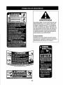
NOTICE REGARDING
EMISSIONS
Engineswhicharecertifiedtocomply
withCaliforniaandfederal
EPAemissionregulations
forSORE(SmallOff RoadEquipment)
are
certifiedto operateon regularunleadedgasoline,andmayinclude
thefollowingemissioncontrolsystems:EngineModification
(EM)and
ThreeWayCatalyst(TWC)if soequipped.
SPARK ARRESTOR
.....
Ir;
This machineis equipped with an internalcombustion engine and
should not be used on or near any unimprovedforest-covered,
brushcoveredor grass-coveredland unless the engine'sexhaust
system is equippedwith a spark arrestor meetingapplicable local or
state laws (if any).
If a spark arrestoris used, it should be maintained in effective working
order by the operator. In the State of Californiathe above is required
by law (Section4442 of the California Public ResourcesCode). Other
statesmay havesimilar laws. Federal tawsapply on federal lands.
A spark arrestorfor the muffleris available through your nearest Sears
Parts and Repair Service Center.
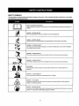
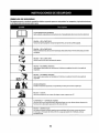
SAFETY SYMBOLS
Thispagedepicts
anddescribes
safetysymbolsthatmayappearonthisproduct.Read,understand,
andfollowatlinstructions
onthemachine
before
attempting
toassemble
andoperate.
READTHE OPERATOR'S MANUAL(S)
Read, understand, and follow all instructions in the manual(s) before attempting
to assemble and
operate
DANGER-- ROTATING BLADES
Never carry passengers. Never carry children, even with the blades off,
O
Always look down and behind before and while backing to avoid a back-over accident.
DANGER-- ROTATING BLADES
_,
WARNING-- ROTATING BLADES
Do not put hands or feet near rotating parts or under the cutting deck. Contact with the blade(s)
can amputate hands and feet.
,,,
WARNING--THROWN
,,,
OBJECTS
This machine may pick up and throw and objects which can cause serious personal injury.
WARNING--THROWN
OBJECTS
This machine may pick up and throw and objects which can cause serious personal injury.
&
,
BYSTANDERS
Keep bystanders, helpers, children and pets at least 7.5feet from the machine while it is in
operation.
WARNING--
SLOPEOPERATION
Do not operate this machine on a slope greater than 15 degrees.
WARNING--
HOT SURFACE
Engine parts, especia]Iy the muffler, become extremely hot during operation. Allow engine and
muffler to cool before touching.
DANGER -- ROTATING BLADES
To reduce the risk of injury, keep hands and feet away. Do not operate unless discharge cover or grass
catcher is in its proper place. If damaged, replace immediately.
7
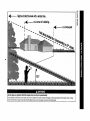
o
Sightandholdthislevalwitha _rtica] tree...
m
ora comerof abuilding...
m
or afencepost
oo
50
Usethis pageas a guideto determineslopeswhereyou maynot operatesafely.
mower could overturn and causeserious injury.Operate riding mowers up and down slopes, never across the face of slopes.
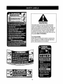
ROTATING BLADES CAUSE
i
SERIOUS INJURY OR DEATH
I
DONOTMOWWHENCH]InRENOROTHERS
ARE I
Mou_
I
•
LOOKDOWNNil) BEHINDBEFORE
ANDWHILE |
_c_,G.
II
NEVEH
CARRY
CHDREN
EVEH
WiTH
BLeaE(S)OFF,
MOWINGfli REVERSE
IS NOTRECOMMENDED.J
WARNING
This symbol points out importantsafety instructions
which, if not followed, could endanger the personal
safety and/or property of yourself and others. Read and
follow all instructionsin this manual before attempting
to operate this machine. Failure to comply with these
instructions may result in personal injury. When you see
this symbol HEED ITS WARNING!
Your Responsibility
Restrict the use of this power machine to persons who
read, understand, and follow the warnings and instructions in this manual and on the machine.
IMPORTANT:
Yourtractorisshippedwithmotoroilin the engine.
However,youMUSTchecktheoil levelbeforeoperating.Referto the
Service& Maintenance
sectionfor instructions
on checkingtheoil
level.
Shipping Brace Removal
Makesuretheridingmower'sengineisoff,removetheignitionkey,
andsettheparkingbrakebeforeremovingtheshippingbrace.Refer
totheOperationsectionfor instructions
on howtosetthe parking
brake.
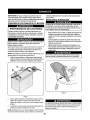
Attaching the Battery Cables
CALIFORNIA
PROPOSITION
65
•
Batteryposts,terminals,andrelated
accessoriescontain
leadand
leadcompounds,
chemicalsknowntotheStateofCaliforniato
causecancerandreproductive
harm.Washhandsafterhandling.
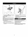
Locatetheshippingbrace,if present,andaccompanying
warning
tagfoundon therightsideof themower,betweenthedischarge
chutedeflectorandthecuttingdeck.SeeFig.2.
Forshippingreasons,bothbatterycablesonyourequipment
may
havebeenleftdisconnected
fromtheterminalsatthefactory.To
connectthe batterycables,proceed
asfollows:
NOTE:Thepositivebatteryterminalis markedPos.(+).Thenegative
batteryterminalismarkedNeg.(-).
1. Removethe plasticcover,if present,fromthe positivebattery
terminalandattachthe redcableto thepositivebatteryterminal
(+)withtheboltandhexnut.SeeFigure1.
2. Removetheplasticcover,if present,fromthe negativebattery
terminal
andattachthe blackcableto thenegativebattery
terminal(-) withtheboltandhexnut.See Figure1.
f
_,,,
J
Figure2
•
•
Placethedecklift leverinthehighestcutting
position.
Referto
SettingtheCuttingHeightintheOperationsectionofthismanual.
Whilepushing
thedischarge
chute
deflector
towards
themachine
with
your
lefthand,removetheshipping
brace
w_ your
righthandbygraspingitbetween
yourthumb
andindex
fingerandrotating
itclockwise.
The shipping brace,used for packagingpurposes only, must be
removedand discarded before operating your riding mower.
Attaching
Figure 1
3.
Positionthe redrubberbootoverthepositive batteryterminal to help
protectitfrom corrosion.
NOTE: If the battery is put intoservice after the date shown on top of
battery,charge the battery as instructedin the Service & Maintenance
section of thismanual prior to operatingthe tractor.
10
The Steering
Wheel
If the steering wheelfor your tractor did notcome attached, the
hardwarefor attaching it has been packed within the steeringwheel,
beneath the steeringwheelcap. Carefullypry off the steeringwheel
cap and removethe hardware.
1.
With the wheels of the tractor pointing straightforward, place the
steeringwheel over the steeringshaft.
2.
Ptacethe washer (with the cuppedside down) overthe steering
wheeland secure with the hex bolt. See Fig, 3-3.
\
1
3.
Figure3
Placethe steering wheel cap over the centerof the steeringwheeI
3.
and push downwarduntil it "clicks"into place.
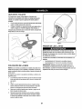
Attaching
The
Seat
4,
Ifthe seat for your tractor was not attached at the factory, referto the
following steps.
NOTE: For shipping reasons, seals are either fastened to the tractor
seat's pivot bracketwith a plastic tie, or mounted backwardto the pivot
bracket, In either case, free the seat from its shipping positionand
remove the adjustment knob from the bottomof seat before proceeding withthe instructions below.
1.
2.
Figure 4
Selectdesired position forthe seat, andsecure withthe adjustment
knob removedeadier.
Position the shoulder screws (found on the base of the seat)
inside the slot openings inthe seat pivot bracket.
Fig. 4.
Toadjustthe positionofthe seat,loosenthe adjustmentknobon the
bottom of the seat. Slide the seat forward or backwardas desired.
Fletightenthe adjustment knob.
Tire Pressure
pressure should be maintained at all times. Neverexceedthe
maximum inflationpressure shown on the sidewall of the tire.
The recommended operatingtire pressureis:
Approximately10 psi for the reartires
Slide the seat slightly rearward in the seat pivot bracket, lining
up the center rear slot inthe pivot bracket withthe remaining hole
in the sears base.
11
Approximately 14 psi for the front tires
IMPORTANT: Referto the tire sidewall for exact tire manufacturer's
recommendedor maximum psi. Do not overinflate.Uneventire pressure could cause the cutting deck to mow unevenly.
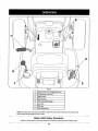
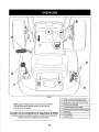
f
B
A
H
D
G
F
E
Figure5
A
Speed Control Lever/Parking Brake Lever
B
Throttle/choke control lever
C
Ignition Switch
D
Deck Lift Lever
E
PTO Lever (Blade Engage)
F
G
,,,Cup,,,Holder
Shift Lever
H
Clutch-Brake Pedal
NOTE- Anyreferencein thismanualtothe RIGHTor LEFTsideofthetractoris observedfromoperator'sseat
positionfacingforwardtowardsthefrontoftractor.
Meets ANS! Safety Standards
Craftsman Tractorsconform to the safetystandard of the American National StandardsInstitute (ANSI).
12
SPEEDCONTROLLEVER
SHIFT LEVER
The speed control lever, locatedon lhe left side of the
tractor's dash console, allows you to regulatethe ground
speed of the lawn tractor. Touse, depressthe clutchbrake pedal and move the leverout of the parkingbrake
notchand forward to increasethe tractor's ground speed.
When a desired speed has been reached, releasethe
lever into an appropriate notchto maintainthat speed.
To slow the tractor's ground speed, depress the clutchbrake pedal and movethe speed control lever rearward
and release it into a notch.
Theshift leveris located on the left
side of the fender and has three
PARKING
BRAKE
Tosetthe parkingbrake,fullydepresstheclutch-brake
pedal.Movethespeedcontrolleverall thewaydownand
intotheparkingbrakeposition.Releasetheclutch-brake
pedaltoallowthe parkingbraketoengage.
I
positions,FORWARD,NEUTRAL
and REVERSE,The clutch-brake
pedal must be depressedand the
tractor mustnot be in motion when
i
the moving shift lever,
((!b)
NOTE: The parkingbrake must be set if the operatorleaves the seat
withthe engine running or the engine will automaticallyshut off.
CONTROL
LEVER
The throttle/choke control lever is located on the right side of the tractor's dash panel.This levercontrols the speed of the engine and when
pushed all the wayforward, the choke control also. When set in a given
position, the throttle will maintain a uniformengine speed.
PTO (BLADE
ENGAGE)
LEVER
Foundon thetractor'srightfender,thePTO(bladeengage)
leveris usedtoengagepowerto thecuttingdeckor other
(separately
available)attachments.
Tooperate,movethe
leverall thewayforward.Movingthe leverall theway
rearwardintothe PTOOFFposition
disengagespowertothe
cuttingdeck/attachment.
NOTE:ThePTO(bladeengage)levermustbein the
disengaged(Pro OFF)positionwhenstartingthe engine.
The tractor's cup holderis located on the fender to the left of
the seat.
SWITCH
SEAT ADJUSTMENT
The key switch module is used to
start and stop the engine. Insert
key into the key switch module
and turn clockwise to the START
KNOB
The seat adjustment knob is located on the bottom side of the seat.
Use this knob to adjust the seat forward or rearwardto a comfortable
operatingposition by loosening the knob, posilioning the seat to the
desired preference,then retighteningthe knob.
position. Releasethe keyinto the
normal mowingposition once engine has started. The headlights
will be activated automatically.
CLUTCH-BRAKE
PEDAL
The clutch-brake pedalis located on the left side of the lawntractor,
along the running board. Depressthe clutch-brake pedal part way
down when slowing the tractor by changing speeds (Referto Speed
Control Lever). Depressthe pedal all the way down to engage the disc
brake and bring the tractor to a complete stop.
To stop the engine,turn the
ignition key counterclockwise to
the STOP position.
NOTE: The pedal must be depressed to start the engine. Referto
Safely InterlockSwitches later in this section of lhis manual.
IMPORTANT: Prior to operatingthe tractor, referto both the "Safety
InterlockSystem"and "Starting The Engine"later in this section of this
manualfor detailed instructionsregardingthe IgnitionSwitch Module.
,_
Foundonyourtractor's
rightfender,thedecklift leveris used
tochangetheheightofthecuttingdeck.Touse,movethe
leverto theleft,thenplacein the notchbestsuitedforyour
application.
CUP HOLDER
IMPORTANT: When operating thetractor withthe cuttingdeck
engaged,the throttle/choke control levermust alwaysbe in the FAST
(rabbit) position.
IGNITION
DECK LIFT LEVER
P/iRK
To releasethe parkingbrake,depress the clutch-brake pedaland
move the speed control lever out of the notches to the desiredposition.
Release the speed control leverand the clutch-brake pedal.
THROTTLE/CHOKE
IMPORTANT: Neverforce the
shift lever.Doing so may resultin
serious damage to the tractor's
transmission.
!_liVlv/_,!
it Iill [l,
Neverleave a running machineunattended,Alwaysdisengage PTO
(Blade Engage Lever),moveshift leverintoneutralposition,set parkng brake,stop eng ne andremovekeyto preventunintendedstarting.
13
Gas and Oil Fill-up
Oil
IMPORTANT:Yourtractorisshippedwithmotoroil in theengine.
However,
youMUSTcheckthe oil levelbeforeoperating.Becareful
notto overfil!.
Forinstructions
on howtochecktheengineoil,referto CheckingThe
EngineOilin theServiceandMaintenance
sectionofthis manual.
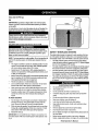
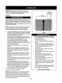
Gasoline
Thegasolinetankis located
underthehood.Donotoverfill.
Figure 6
SAFETY
NOTE : Purchasegasolineinsmallquantities.Donotusegasolineleft
overfromthepreviousseason,to minimizegumdeposits
in thefuel
system.
•
Thisengineiscertifiedtooperateon unleadedgasoline.Forbest
results,fill thefueltankwithonlyclean,fresh,unleadedgasoline •
witha pumpstickeroctaneratingof87 or higher.
•
Gasohol(upto 10%ethylalcohol,90%unleaded
gasofineby
•
volume)is an approvedfuel.Othergasofine/alcohol
blends,such
as E85,are notapproved.
,
MethylTertiaryButylEther(MTBE)andunleadedgasofineblends •
(uptoa maximumof 15%MTBEbyvolume)areapprovedfuels.
Othergasoline/ether
blendsare notapproved.
•
Fillfueltankoutdoorsor in well-ventilated
area.
•
Donotoverfillfueltank.Filltankto nomorethan1/2inchbelow
bottomoffillerneckto allowspaceforfuelexpansion.
•
•
Neverremovegascapor addfuelwhiletheengineishotor running.Allowenginetocoolat leasttwominutesbeforerefueling.
•
If gasolineisspilled,wipeit offtheengineandequipment.Move
machinetoanotherarea.Wait5 minutesbeforestartingthe
engine.
TO Add Gasoline
Fillthe fuel tankwith gasoline.Useonly clean,fresh (no morethan
30 days old), unleadedgasoline. Filltank to no morethan 1/2 inch
below bottomof filler neckto allowspacefor fuelexpansion.
3.
Reinstallthe fuel cap.
IMPORTANT:
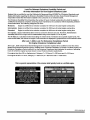
The safety interlocksystem preventsthe engine from starting
unless the parkingbrake is engaged and the PTO (Blade Engage)
lever is in the disengaged(OFF) position.
The safety interlocksystem will automatically shut off the engine if
the operator leaves the seat beforeengaging the parkingbrake.
The safetyinterlocksystemwill automaticallyshut off the engineif
the operator leavesthe tractor'sseat withthe PTO(Blade Engage)
leverengaged,regardlessof whetherthe parkingbrake is engaged.
The engine willautomaticallyshut off if the PTO(Blade Engage)
leveris moved into the engaged (ON) position with the shift lever
in Reverse.
F: " FLI"tR11'
Avoid Serious Injury or Death
Go UPand down slopes, not across.
Avoid sudden turns.
Do not operate the unit whereit could slip or tip.
If machinestops going uphill, stop blades and back downhill
slowly.
Do not mow when children or othersare around.
Nevercarry children, evenwith blades off.
Turnthe engine offand let engine cool at least 2 minutes before
removingthe fuel cap. The gasoline tank is locatedunder the
hood. Removethe fuel cap byturning it counterclockwise.
2.
SYSTEM
The safety interlock systemis designedfor safe operation of the tractor. Ifthis systemshould ever malfunction, do not operate the tractor.
Immediatelycontact 1-800-4-MY-HOMEto havethe systemserviced.
.
1.
INTERLOCK
Look down and behind beforeand while backing.
Keep safety devices (guards,shields, and switches) in place
and working.
Removeobjects that could be thrown by the blades,
Know location and function of all controls.
Be sure blades and engineam stoppedbefore placinghands or
feet near blades.
Do not overfill thetank. Fill tank to no morethan 1/2
•
inch below bottomof filler neck to allow spacefor fuel expansion.See
Fig. 6.
Before leavingoperator'sposition, stop tractor, disengage
blades, engage parkingbrake,shut engine off, and removekey.
Read Operator's
14
Manual
IGNITION SWITCH
SETTING THE CUTTING HEIGHT
Theignitionswitchis activatedto starttheengine,insertkeyintothe
ignitionswitchandturnclockwiseto theSTARTposition.Releasethe
keyintotheONposition onceenginehasfired.See Fig.7.
Tostoptheengine,turnthe ignition
keycounterclockwise
tothe OFF
position.SeeFig.7.
1. Selecttheheightpositionof thecuttingdeckbyplacing
thedeck
lift leverin anyofthesix differentcuttingheightnotches
on the
rightsideofthefender.
NEVERleavea running
machine
unattended.
Alwaysdisengage
PTO,moveshiftleverintoneutralposition,setparkingbrake,stop
engineand removekeyto preventunintended
starting.
STARTING THE ENGINE
On
NOTE:RefertotheGasolineandOiJfill-upinstructions
earlierin this
section.
Start
off
1.
2.
Insertthetractorkey intotheignitionswitch.
PlacethePTO(BladeEngage)leverin thedisengaged(OFF)
position.
3. Engagethetractor'sparkingbrake.
4. Activatethechokecontrolbymovingthethrottletchoke
leverall
thewayup intothechokeposition.
5. Turntheignitionkeyclockwisetothe
STARTposition.
Aftertheengine
starts,releasethekey.It willreturnto theON(orNormalMowing)
position.
DO NOT hold the keyin the STARTposition for longerthan ten
seconds at a time. Doing so may cause damage to your engine's
electric starter.
Figure 7
IMPORTANT:Priortooperating
thetractor,
refertobothSafety
interlock
SystemandStartingTheEngineintheOperationsectionof
this manualforfurtherdetailedinstructions.
ENGAGING
THE PARKING
6.
NOTE: Do NOT leave the chokecontrolon whileoperatingthe tractor.
Doingso willresultin a "rich" fuel mixtureand cause the engine to run
poorly.
BRAKE
To engage the parking brake:
1.
2.
3.
Fuflydepresstheclutch-brake
pedalandholditdownwithyourfoot.
Movethespeedcontrolleverallthewaydownand intotheparking
brakeposition.
Releasetheclutch-brake
pedaltoallowtheparkingbraketoengage.
To release the parking
1.
After the engine starts, deactivatethe choke controland place the
throttle control inthe FASTposition.
brake:
Depresstheclutch+brake
pedalandmovethespeedcontrollever
outofthe parkingbrakepositionand intoa desiredspeed.
15
STOPPING
THE ENGINE
1.
2.
3.
Ifyoustrikea foreignobject,stoptheengine,disconnectthespark
plugwire(s)andgroundagainsttheengine.Thoroughlyinspect
the
machineforanydamage.Repairthedamagebeforerestartingand
operating
1.
ifthebladesare engaged,placethe PTO(BladeEngage)leverin
thedisengaged
(OFF)position.
2. Turntheignitionkeycounterclockwise
to theSTOPposition.
3. Removethe keyfromtheignitionswitchto preventunintended
starting.
DRIVING THE TRACTOR
Avoidsudden starts, excessivespeed and suddenstops.
Placetheshiftleverinneutral,
Engagetheparkingbrake,
Shutengineoff and remove
thekey.Doingsowillminimizethe
possibilityofhavingyourlawn"browned"byhotexhaustfrom
yourtractor'srunning
engine.
If unitstallswithspeedcontrolin highspeed,or ifunitwillnotoperate
withspeedcontrolleverina lowspeedposition,proceedasfollows:
1+ Placeshiftleverin NEUTRAL.
2.
3.
4.
5+
6.
7.
Restartengine.
Placespeedcontrolleverin highestspeedposition.
Releaseclutch-brakepedalfully.
Depressclutch-brakepedal.
Placespeedcontrolleverin desiredposition.
Placeshiftleverin eitherFORWARD
or REVERSE,
andfollow
normaloperatingprocedures.
DRIVING
ON SLOPES
RefertotheSLOPEGAUGEinthe SafetyInstructions
sectionofthe
manualtohelpdetermineslopeswhereyoumayoperatethistractor
safely.
Do not leavethe seat of the tractor withoutfirst placingthe PTO
(Blade Engage) leverin the disengaged(OFF) position, depressing
the brake pedal and engagingthe parking brake. If leavingthe tractor
unattended,also turn the ignitionkeyoff and removethe key.
Do not mow on inclines witha slope in excess of 15 degrees (a rise
of approximately 2-1/2feet every 10 feet). The tractor couldoverturn
and cause serious injury.
•
Mow up and down slopes, NEVERacross.
Exercise extreme caution whenchangingdirection on slopes.
Watch for holes, ruts, bumps, rocks,or other hidden objects.
Uneventerrain could overturnthe machine.Tall grass can hide
obstacles.
1.
Depress the clutch-brakepedalto releasethe parking brake and
then let the pedal up.
•
•
2.
3.
Movethe throttle leverinto the FAST(rabbit) position.
Place the shift leverin either the FORWARDor REVERSE
position.
,
Avoid turns when driving on a Slope.If a turn must be made,turn
down the slope. Turning up a slope greatly increasesthe chance
of a roll over.
•
Avoid stoppingwhendriving up a slope. If it is necessaryto stop
whiledriving up a slope,start up smoothly andcarefully to reduce
thepossibilityof flipping the tractor over backward.
IMPORTANT: Do NOT use the shift leverto changethe directionof
travel whenthe tractor is in motion.Always use the clutch-brake pedat
to bring the tractor to a complete stop beforeshifting.
4.
Releasethe parking brake by depressing the clutch-brake pedal
and positioningthe speed control lever in the desiredposition.
ENGAGING
IMPORTANT: First-timeoperatorsshould use speed positions1or
2. Become completelyfamiliarwiththe tractor'soperationand controls
before operating the tractor in higherspeed positions.
5.
Releaseclutch-brakepedal slowly to put unit into motion.
6.
The lawntractor is brought to a stop by depressing the clutchbrake pedal.
2.
3.
NOTE: When operating the unit initially,therewillbe little difference
betweenthe highest two speeds until after the belts haveseated
themselvesinto the pulleys duringthe break-in period.
rP1
THE BLADES
Engagingthe PTO(Blade Engage)transfers powerto the cutting deck
or other(separately available)attachments.To engage the blades,
proceed as follows:
1. Movethe throtUeichokecontrol leverto the FAST(rabbit) position.
[.el
Graspthe PTO (Blade Engage)leverand pivot it all the way
forward into the engaged (ON) position.
Keepthe throttle leverin the FAST(rabbit) positionfor the most
efficient use of the cutting deck or other (separatelyavailable)
attachments.
NOTE: The engine will automaticallyshut off if the PTO (Blade
Engage)lever is moved into the engaged (ON) positionwith the shift
leverin Reverse.
WARNING! Beforeleavingthe operator'spositionfor any reason,
disengage the blades,place the shift lever in neutral, engage the
parkingbrake,shut engine off and remove the key.
IMPORTANT;Whenstoppingthetractor
foranyreasonwhileon a
grasssurface,always:
16
HEADLIGHTS
MULCHING
A mulch kit isavailable asan attachment, Mulching isa processof
recirculating grassclippings repeatedly beneath the cutting deck,
The ultra-fine clippings arethen forced back into the lawn where
. they act asa natural fertilizer.
A mulch kit can be purchased.See the Replacement Parts & Attachments section of this manualfor more information.
USING THE DECK LIFT LEVER
To raisethe cuttingdeck,movethe deck lift leverto the left, then place
it in the notch best suited for your application. Referto Setting The
Cutting Height earlierin this Operation section.
MOWING
I_he
machine
while it is in operation. Stop machineif anyone entersthe area.
The following information will be helpful when using the cutting deck
with yourtractor:
Planyourmowingpattern
toavoiddischargeof materialstoward
roads,sidewalks,bystanders
andthelike.Also,avoiddischarging
materialagainsta wallor obstructionwhichmaycausedischarged
materialto ricochet
backtoward
theoperator.
•
Do not mowat high ground speed, especially if a mulch kit or
grass collector is installed.
•
For best results it is recommendedthat the first two laps be cut
with the discharge thrown towards the center.After the first two
laps, reversethe direction to throw the discharge to the outside
for the balance of cutting. This willgive a better appearanceto the
lawn.
•
Do not cut the grasstoo short. Short grass invitesweed growth
and yellowsquickly indry weather.
Mowing should alwaysbe done with the engine at full throttle.
•
•
Under heavier conditions it may be necessary to go back overthe
cut area a second time to get a clean cut.
•
Do NOT attemptto mow heavy brush and weedsand extremely
tall grass. Your tractor is designedto mow lawns, NOT clear
brush.
•
Keep the blades sharp and replacethe blades when worn. Refer
to Cutting Bladesin the-Servicesection of this manualfor proper
blade sharpening instructions.
17
,
The lamps are ON wheneverthe tractor's engine is running.
,
The lamps turn OFF when the ignition keyis moved to the STOP
position.
MAINTENANCE
Before
performing
anytypeof maintanance/ser_ce,
disengage
all
1
controlsandstoptheengine.
Waituntilall movingpartshavecometo t
a complete
stop.Disconnect
sparkplugwireandgrounditagainstthe t
enginetopreventunintended
starting.AlwayswearsafetyglassesduringI
operation
orwhileperforming
anyadjustments
orrepairs,
i
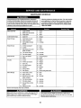
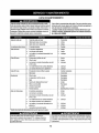
SCHEDULE
Followthemaintenance
schedulegivenbelow.Thischartdescribes
serviceguidelines
only.UsetheServiceLogcolumn
tokeeptrack
ofcompletedmaintenance
tasks.To locatethe nearestParts&
RepairServiceCenteror to scheduleservice,simplycontact
1-800-4-MY-HOME®.
I_
BeforeEachUse
_
1.
2.
Engine oi!level
Mufflerarea and controls
4.
5.
Check
Clean
3.
Fingerguard
6.
Clean
In the First Five Hours
7.
Engine Oil
8.
Change
Ever),10 Hours
9.
Hood/Dash air vents
12. Clean
Every25 hours
10. Battery terminals
11. Deck spindlesand idler
bracket
13. Clean
14. Lubricate
15. Air filter's precieaner*
16. Air filter*
20. Clean
2I. Clean
22. Lubricate
17. Mid steering arms, pivot
shafts, and axles
18. Front wheel bearings
19. Front deck wheels
23. Lubricate
Every 50 hours
25. Engine oil/Oil fitter
26. Muffler
27. Change! Replace
28. Check
Annually
29. Air filter
36. Replace
37. Replace
38. Replace
30. Air filter's pre-cfeaner
31. Spark plug
32. Air coolingsystem*
33. Fuelfilter
34. Steering Gears
35. RearWheels
BeforeStorage
[_l_j
24. Lubricate
39. Clean
40. Replace
41. Clean
42. Removeand grease axles
43. Hood/Dash air vents
50. Clean
44. Battery terminals
51. Clean
45. Mid steeringarms, pivot
shafts, and axles
52. Lubricate
46. Front wheel bearings
47. Front deck wheels
53. Lubricate
54. Lubricate
48. Deck spindlesand idler
bracket
55. Lubricate
49. Pedalpivot points
56. Lubricate
*Service merefrequently under dusty conditions.
Before performing any maintenanceor repairs,disengage the PTO
(Blade Engage Lever), engage the parkingbrake,stop the engine
and remove the key to preventunintendedstarting.
If the engine has been recently run,the engine,muffler and surrounding metal surfaceswill be hot and can cause burns to the skin.
Exercisecaution to avoid burns.
18
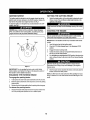
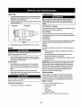
ENGINE
Checking
MAINTENANCE
Changing
OnlyusehighqualitydetergentoilratedwithAPIserviceclassification
1.
SF,SG,SH,orSJ.Selecttheoil'sSAEviscosity
gradeaccordingto
theexpected
operating
temperature.
Follow
thechartbelow.
2.
Althoughmulti-viscosity
oils(5W20,10W30,etc.)improve
starting
3.
incoldweather,
theywillresultinincreasedoilconsumption
when
usedabove32°1:.Checkyourengineoillevelmorefrequentlytoavoid
4.
possibleenginedamagefromrunninglowonoil.
32°F
_ Warmer
_
5.
SAE30
6.
Oil Viscosity Chart
7.
j
8.
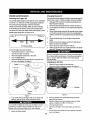
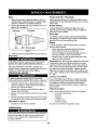
To checkthe engine oil, proceedas follows:
•
Ensurethatthe tractoris on a levelsurface.
•
1.
Oil
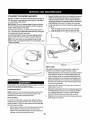
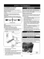
Theengine oilshouldbechangedin thefirst5 hoursandthenevery50
hours or oncea season. Tochangethe engine oil,proceed as follows:
the Engine Oil
/CColder _
Engine
With engine OFF but still warm,disconnectsparkplug wireand
keepit awayfrom spark plug.
Removethe oil fill capldipstickfrom the oil fill tube.SeeFigure9.
Turnthe steeringwheelall lhe wayto the rightto betterexposethe
drain plug.
Clip the oil drainsleeve (packedwith this manual)onto the oil drain
port. Routethe oppositeendof the sleeve into an appropriateoil
collectioncontainerwitha capacitygreatenough tocollectthe used
oil,
Removethe oil drain plug,The oil will beginto drain out of the
engine.
After the oil has finisheddraining,replacethe oil drain plug and
tighten.Be carefulnot to overtighten.
Removethe oitdrain sleeveand storefor lateruse.
Refillthe engine withnew motoroil untilthe oil levelon the dipstick
reads FULL, Replacethe oil fill cap/dipstick.
Clean the oil fill area of any debris.
Removethe dipstick and wipewitha clean cloth.
2,
Insertand tighten dipstick.
3.
Removethe dipstick and check the oil level.It should be at the
Full mark on the dipstick. See Figure 9.
It'_ist
recyclingfacilities.
Changing
Dipstick__
of safe disposal!
the Oil Filter
"L
Drainthe oil from the engineas describedabove.
2.
Removethe oil filter and disposeof properly.See Figure10.
Oil Drain
Valve
- Oil Filter
Oil Drain
Sleeve
4.
J
Figure 10
Figure 9
If low,add oil slowly into the engine oilfill. Do not overfill.After
adding oil, wait one minute and thenrecheckthe oil level.
3.
4.
5.
5.
Replaceand tightendipstick.
19
Beforeyou installthenew oil filter,lightlylubricatethe oil filter
gasketwith fresh, clean oil.
Installthe oil filter by hand untilthe gasketcontacts the oilfilter
adapter,thentighten the oil filter I/2 to 3/4 turns,
Add oil as describedabove.
6.
Start and run the engine.As the engine warmsup, check for oil
leaks.
7.
Stop the engine and check the oil level. It should be at the FULL
mark on the dipstick.
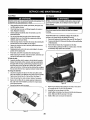
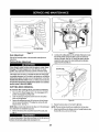
Fuel Filter
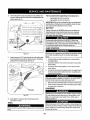
Air Cleaner
Gasoline
anditsvaporsareextremelyflammableand explosive.Fire
or explosioncancausesevereburnsor death.
,
Keep gasoline awayfrom sparks, openflames, pilot lights, heat,
and other ignitionsources,
•
Check fuel lines,tank, cap, and fittings frequently for cracks or
leaks. Replaceif necessary.
•
Before replacingthe fuel filter,drain the fuel tank as per the
instructions below.
•
Do not drain fuel when the engine is hot.Allow the engine
adequate time to cool. Drainfuel into an approvedcontainer
outdoors, awayfrom open flame.
,,
Drain any large volumeof fuel from the tank by disconnecting the
fuel line from the in-line fuel filter near the engine.
•
Remove the fuel line from the In-lineside (side towards the fuel
tank) of the fuel filter.
Replacement parts must be the same and installedin the same
positionas the original parts.
,
If filters,or coversarenotinstalledcorrectly
sedousinjuryor death
couldresultfrombackfire.Donotattempttostarttheenginewith
themremoved.
Donotusepressurized
air or solventsto cleantheair cleaner
cartridge.
Theair filtersystemusesa cylindrical
cartridge.
Thismodelalso
includesa pre-cleaner
thatcanbewashedandreused.
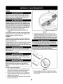
1. Removethefasteners(A)andtheair filtercover(B),SeeFigure12.
2. Toremovethefilter(C),lifttheendofthefilterandthenpullthefilter
off theintake(D).
3. Removethepre-cleaner
(E),if equipped,fromthefilter.
4. Toloosendebris,gentlytapthefilteron a hardsurface,if thefilter
is excessively
dirty,replacewitha newfilter.
•
•
If fuel spills, waituntil it evaporatesbefore starting engine.
Before replacingthe fuel filter, drain the fuel tank.Otherwise,fuel
can leak out andcause a fire or explosion.
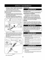
To Drainthe fuel:
A
I.
Locatethe fuel filter,which isroutedon the left sideof the engine
betweenthe fueltank andthe carburetor,and maybe attachedto
the enginewith a tie strap. Cutthe tie strap, if present,then pinch
the in-lineclampon the fuel filter with a pairof pliers,slidethe
clamp up the fuel line.Pullthe fuel linefree from the filter and place
the open endof the line intoan approvedcontainerto drainthe fuel.
To change the fuel filter:
1.
2.
3.
4.
Use pliers to squeezethe tabs on the other clamp (the out-line
side of the fuel filter), then slide the clamp awayfrom the fuel filter,
Twistand pullthe fuel line off of the fuel filter.See Figure11.
Check the fuel linesfor cracks or leaks. Replace if necessary.
Replacethe fuel filter withan original equipment replacement
filter. Call 1-800-4-MY-HOME@to purchasethe originalequipment replacement filter.
J
Figure 12
Securethe fuel lines withthe clamps.
5.
6.
7.
Clamp
Line
Fuel
8.
Tab
....
J
Figure11
2O
Wash the pre-cleaner in liquid detergent andwater.Then allow it
to thoroughlyair dry. Do not oil the pre-cleaner.
Assemble the dry pre-cleanerto the filter.
Installthefilter on the intake.Pushthe endof the filterintothe baseas
shown. Make surefilter fits securely inthe base.
Install air filter cover and secure with fasteners.
LUBRICATION
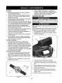
Spark Plug
1.
2.
Cleanareaaroundthesparkplugbase.Donotsandblast
sparkplug.
Sparkplugshould
be creaned
byscraping
orwirebrushingand
Beforelubricating,
repairing,orinspecting,
alwaysdisengagePTO
washing
witha commercial
solvent
(BladeEngageLever),moveshiftleverintoneutralposition,set
Remove
andinspect
thespark
plug.Checkgaptomakesureitisset
parkingbrake,stopengineand removekeyto preventunintended
at .030".See Figure13.
starting.
Electrode
Porcelain
Pivot Points & Linkage
Lubricateall thepivotpointson thedrivesystem,parkingbrakeandlift
linkageat leastoncea seasonwithlightoil.
Rear Wheels
Therearwheelsshouldberemovedfromtheaxlesoncea season.
Lubricatethe axlesandtherimsweftwithan all-purposegreasebefore
re-instaUing
them.
Front Axles
.030 (.76 ram) gap
_,,,,,
Eachendof the tractor's front pivot bar may be equipped witha grease
fitting. Lubricatewith a grease gun after every 25 hours of tractor
operation.
...........
Figure13
3.
Replace
thesparkplug(Champion®RC12YC)
oncea season.
Muffler
Battery
The battery is sealed and is maintenance-free.Acid levels cannot be
checked.
•
i Temperature
of mufflerand nearbyengineareasmayexceed150"F
(65'C).Avoidcontactwiththeseareas.
Always keepthe battery cables and terminalscleanand free of
corrosive build-up.
•
•
•
Nter cleaning the battery andterminals, apply a lightcoat of
petroleumjefly or grease to both terminals.
Alwayskeep the rubberboot positionedover the positive terminal
toprevent shorting.
Inspect muffler periodically,
and replaceif necessary. Replacernent parts for the muffler must be the same and installedinthe
same position as the original parts.
Clean
•
IMPORTANT: If removingthe batteryfor any reason,disconnect the
NEGATIVE(Black) wire from itsterminalfirst, followedby the POSiTIVE (Red) wire. When re-installing
the battery,alwaysconnect the
POSITIVE (Red) wire to its terminalfirst, followed by the NEGATIVE
(Black) wire. Be certain that the wires are connected to the correct
terminals; reversingthem could changethe polarity and resultin
damage to your engine's aFternatingsyslem.
Engine
Daily or beforeevery use, clean grass, chaff or accumulated
debris from engine. Keeplinkage, spring, and controls clean.
Keep area around and behind muffler free of any combustibJe
debris.
•
•
Keeping engine clean allowsair movementaround engine.
•
Engine partsshould be kept clean to reduce the riskof overheating and ignitionof accumulateddebris.
Cleaning
Clean the battery by removing it from the tractorand washingwith
a baking soda and water solution, if necessary, scrape the battery
terminals with a wire brush to removedeposits. Coat terminalsand
exposed wiring with grease or petroleumjelly to prevent corrosion.
system.Usea brushordrycloth.
Carburetor
•
Battery
Battery
Adjustment
Failures
Some commoncauses for batteryfailure are:
•
Incorrect initial activation
Thecarburetoron thisengineisnotadjustable.
•
Overcharging
•
•
,
Freezing
Undercharging
Corrodedconnections
Thesefailures are NOT covered by yourtractor'swarranty.
21
CLEANING
THE
ENGINE
AND DECK
2.
Anyfuelor oil spilledonthemachineshouldbewipedoff promptly.Do
NOTallowdebristo accumulatearoundthecoolingfins ofthe engine
oron anyotherpartofthe machine.
IMPORTANT:Theuseof a pressurewasherto cleanyourtractoris
NOTrecommended.
It maycausedamageto electricalcomponents,
spindles,pulleys,bearingsor theengine.
A screwplugcanbe foundon yourtractor'sdecksurfaceas seenin
Fig.14.This plugcanbe replacedwitha waterporttobe usedas part
ofa separately-available
deckwashsystem.
TheDeckWashSystem
TM is usedto rinse
grassclippingsfromthe
deck'sundersideandpreventthe buildupofcorrosivechemicals.
Measure
thedistance
fromthefrontofthe bladetiptotheground
andtherearof thebladetipto theground.Thefirstmeasurementtakenshouldbebetween¼"and"_"lessthanthesecond
measurement.
Determine
theapproximate
distancenecessaryfor
proper
adjustmentandproceed,ifnecessary,tothenextstep.
3. Locatetheflangelocknutonthefrontsideofthestabilizerbracket.
SeeFig.I5.
,
Tightentheflangelocknutto raisethefrontofthedeck;
i)
Loosentheflangelocknutto lowerthefrontofthedeck.
f
NOTE:A deckwashsystemcanbepurchased
throughtheretail
locationin whichyoupurchasedthis tractor.Formoreinformation,
catl
1-800-4-MY+HOME@.
Figure I5
Side to Side
If the cutting deck appearsto be mowing unevenly,a side to side
adjustment can be performed.Adjust if necessary as follows:
1. Withthetractor parkedona firm,levelsurface,placethe decklift lever
inthe second from the top notch (second highest position)and
rotateboth blades so that they are perpendicularwith the tractor.
,,J
Figure 14
2.
Measurethe distance from the outside of the teft blade tip to the
groundand the distance from the outside of the rightblade tipto
the ground. Bothmeasurementstaken should be equal. If they're
not, proceed to the next step.
3.
Loosen,but do NOT remove, the hex cap screw on the left deck
hanger bracket.See Fig.16.
4.
Balancethedeckbyusingawrenchtoturntheadjustment gear (found
immediatelybehind the hex cap screw just loosened) clockwise/
up or counterclockwise!down.The deck is propertybalanced
when both blade tip measurementstaken earlierare equal.
5.
ReUghtenthe hex cap screw on the left deck hanger bracketwhen
proper adjustment is achieved.
ADJUSTMENTS
Leveling the Deck
NOTE:Checkthetractor'stirepressurebeforeperforming
anydeck
leveling
adjustments.Referto Tiresin theServicesectionof this
manualfor moreinformation
regardingtirepressure.
Front To Rear
The front of the cutting deck is supported by a stabilizer bar that can
be adjusted to level the deck from front to rear.The front of the deck
should be between ¼-inch and3,_-inchlower than the rear of the deck.
Adjust if necessary as follows:
1.
With the tractor parkedon a firm, level surface,place the ]ever for
lifting the platform on the second to the top notch (second
highest position)and rotatethe blade as close as possibleto the
discharge channel thatis parallel to the tractor.
22
f
Hex Cap Screw
J
Figure17
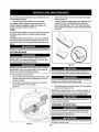
Looking at the cutting deck from the left side of the tractor,locate
the bow-tiepin thatsecures the deck support rod on the rear
left side of the deck. See Fig. 18. Removethe bow-tie pin that
secures the deck support rod, and carefully removethe deck
support from the deck lift arm.
J
_,.,,,,,,
Figure16
Seat Adjustment
Referto theAssembly section of thismanualfor seat adjustment
instructions.
Parking
Brake Adjustment
f
Never attempttoadjustthe brakes whilethe engineis running.Always
disengage PTO (bladeengage)lever,moveshift lever intoneutral
position, stop engine and removekeyto preventunintended
starting.
Bow-TieClip
J
If thetractor
doesnotcometo a completestopwhenthebrakepedal
iscompletelydepressed,
or if thetractor'srearwheelscan rollwiththe
parkingbrakeapplied,thebrakeisin needofadjustment.
Contactthe
nearestSearsServiceCenterto haveyourbrakesproperlyadjusted.
TolocatethenearestParts&RepairServiceCenterortoschedule
service,contact1-800-4-MY-HOME®,
CUTTING
DECK
To remove
the cutting
1.
2.
3.
REMOVAL
deck, proceed as follows:
Place the PTO (Blade Engage) leverin the disengaged (OFF)
position and engage the parkingbrake.
Lower the deck by moving the deck lift lever into the bottom
notch on the right fender.
....................... J
Remove the self-tappingscrew (A)that secures the belt-keeper
rodfrom around the tractor's PTOpulley,then remove the belt
keeper rod (B), See Fig. 17.
Figure 18
6.
NOTE; Make a mental note what hole the otherend of the belt-keeper
rod is inserted in for reinstallationpurposes.
4.
Removethe belt (C) from around the tractor's PTO pulley.See
Fig. 17.
23
Repeatthe above stepson the tractor's right side.
NOTE=The bow-tie clips should be re-installedfrom the top down.
7.
Movethe deck lift leverintothe top notchon the rightfenderto raise
the decklift arms up and out of the way.
8.
f
Removethe bow-tie cotter pin securingthe deck stabilizerrod to
the deck. Slide the deck tiftrod from the mountingbracket on the
deck as seen in Fig. 19.
-..,
The recommended
operating tire pressure is:
,
Approximately
10psiforthereartires
° Approximately
14psiforthefronttires
IMPORTANT:Refertothetiresidewallforexacttiremanufacturer's
recommended
ormaximum
psi,Donotoverinflate,
Uneventirepressurecouldcausethecutting
decktomowunevenly.
Califomia Proposition 65 WARNING!Battery posts, terminals,and
related accessoriescontain lead and lead compounds, chemicals
known to the State of California to causecancer and reproductive
harm, Wash handsafter handling.
_OSITIVE
(Red) wire to
its terminal first, followedby the NEGATIVE(Black) wire.
JUMP
STARTING
J
Figure 19
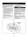
g,
Carefullyremovethe PTO cable from the rear of the cutting deck
by removing the bow-tie cotterpin which secures it. Remove the
spring from the deck idlerbracket.See Fig.20.
1.
2.
3.
4.
Connect positive (+) cableto positive post (+) of your tractor's
discharged battery.
Connect the other end of the cable to the (positive +) post of the
jumper battery.
Connect the second cable (negative -) tothe other post of the
jumper battery.
Connect the otherend of the negativecable to the engine block of
the tractor,away from the battery.Attach to an unpainted part to
assure a good connection.
Ifthe jumper battery is installed on a vehicle (i.e. car, truck), do NOT
start the vehicle'sengine whenjump startingyour tractor.
/
/
5.
6.
/
/
/
Start the tractor (as instructedearlierin thissection of thismanual).
Set the tractor's parking brake before removing the jumper cables,
in reverseorder of connection.
f
/
CHARGING
/
/
PT0 Cable
,J
IBatteries give off an explosivegas while charging. Chargethe batteryI
in a well ventilatedareaand keepawayfrom an open flame or pilot I
light as on a waterheater, space heater,furnace, clothes dryeror
I
other gas appliances.
I
Figure20
10. Gentlyslidethecuttingdeck(fromtheleft side)outfrom
underneath
thetractor,
TIRES
lF; lrir/ l'itT
.dlI_
Neverexceedthe maximum inflationpressure shown on the sidewall
of t re.
24
Ifyourtractorhasnotbeenputintouseforan extended
periodof time,
chargethebatteryasfollows:
1. Setyourbatterychargerto delivera maxof 10amperes.
If yourbatterychargerisautomatic,chargethe batteryuntilthe
chargerindicates
thatchargingiscomplete,
tf thecharger
is not
automatic,
chargeforno fewerthaneighthours.
FUSE
One20AMPfuseisinstalled
inyourtractor'swiringharnesstoprotect
thetractor's
electricalsystemfromdamagecausedbyexcessive
amperage.
if theelectricalsystemdoesnotfuncfion,or yourtractor'senginewill
notcrank,firstcheckto be certain
thatthefusehasnotblown,it can
befoundatthe rearof theunit,underneath
thefenderlocatedbythe
battery.
CUTTING
3.
Removethe hexflangenutthatsecuresthebladeto thespindle
assembly.SeeFig.21.
4. Toproperly
sharpenthecuttingblades,remove
equalamountsof
metalfrombothendsof thebladesalongthecuttingedges,
paralleltothetrailingedge,at a 25° to 30° angle.Alwaysgrind
eachcutting
bladeedgeequallyto maintainproperbladebalance.
See Fig.22.
_'-
BLADES
Shuttheengineoffandremoveignitionkeybeforeremovingthe
cutting
blade(s)forsharpeningorreplacement.
Protect
yourhands
byusng heavygoveswhengraspngtheb ado.
Figure 22
Toremovetheblades,proceedas follows.
1. Removethedeckfrombeneaththetractor,(refertoCuttingDeck
Removalearlierin thissection)thengentlyflip thedeckoverto
exposeits underside.
2. Placea blockofwoodbetweenthecenterdeckhousingbaffle
andthe cuttingbladeto actasa stabilizer.
SeeFig.21.
5.
Testthe blade'sbalanceusing ablade balancer.Grindmetalfromthe
heavy side until it balances evenly.
NOTE; When replacingthe blade, be sure to install the blade with the
side of the blade marked "Bottom" (or witha part number stamped in
it) facingthe ground when the mower is in the operating position.
Use a torque wrenchto tightenthe blade spindrehex flange nut to
between70 Ibs-ft and 90 Ibs-ft.
CHANGING
THE DECK
,,,
BELT
...... ,..........
All beltson yourtractoraresubjecttowearandshouldbe replacedif
Figure 21
anysignsof wearare present.
25
IMPORTANT:TheV-beltfoundonyourtractorisspecially
designed
toengageanddisengagesafely.A substitute(non-OEM)V-beltcan
bedangerousbynotdisengaging
completely.
Fora properworking
machine,useidenticalequipmentbeltsas listedin thepartspagesof
thisOperator'sManual.
Tochangeor replacethedeckbelton yourtractor,proceedasfollows:
1. Removethedeckas instructedearlierin thissection.
2.
3.
4.
5.
6.
7.
8.
9.
10.
1t. Whileholdingthebeltandpulleytogether,rotatethepulleytothe
left.Continueholdingandrotatingthepulleyandbeltuntilthebelt
isfully rolledintothePTOpulley.
PARKING
BRAKE ADJUSTMENT
Neverattempttoadjustthebrakeswhiletheengineisrunning.Always
disengagePTO(BladeEngageLever),moveshiftleverintoneutral
position,stopengineandremove
keytopreventunintended
starting.
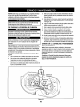
Removethe beltcoversfromthe spindlepulleysbyremovingthe
hexscrewsthat fastenthecovers
to thedeck.SeeFig.23.
It mayalsobe necessaryto loosenthehexnutontheleft deck
idlerpulleytogetthe beltoff thepulleyandaroundthebeltguard.
Carefullyremovethedeckbeltfromaroundthetwospindle
pulleysandthetwodeckidlerpulleys.SeeFig.23.
Toplacethenewbelt,beginby routing
thebeltaroundthetwo
outerspindlepulleys
asshownin Fig.23.
Thenroutethebeltaroundthetwodeckidlerpulteys
asshownin
Fig.23.
Retightenthebeltkeeperrodloosenedearlier.
Remountthebeltguardsremovedearlier.
Re-installthedeck,makingsurethebeltremainsroutedaround
the pulleysas instructed.
Thecompletebeltroutingis shownin
Fig.23.
Pulltherightsideofthebelt,and placethenarrowV sideof the
beltintothe PTOpulley.
If thetractordoesnotcometo a completestopwhentheclutch-brake
pedaliscompletelydepressed,or ifthetractor'srearwheelscanroll
withtheparkingbrakeapplied,thebrakeisin needofadjustment.
Contactthe nearestParts & RepairServiceCenterto haveyour
brakesserviced.
TolocatethenearestParts& RepairServiceCenteror toschedule
service,contact1-800-4-MY-HOME®.
CHANGING
BELT
To locatethenearestParts&RepairServiceCenterortoschedule
service,contact1-800-4-MY-HOME®.
/(/" !l
He_
_/spier
__ndie
_
DRIVE
NOTE:Severalcomponents
mustbe removedandspecialtools(i.e.
aidimpactwrench)in
orderto changethetractor'sdrivebelt.Contact
the nearestParts &RepairServiceCentertohaveyourtransmissiondrivebeltserviced.
_
- -'--'-_--'-'----_
THE TRANSMISSION
"_,,_..._I_
/_'_
This portion of the
belt routes around
the PTO Pul|ey
pul,ey
Figure 23
26
Neverstorelawntractor
withfuelintankindoors
or inpoorly
ventilated
areaswherefuelfumesmayreachan openflame,spark,
orpilotlightason a furnace,waterheater,
clothes
dryer,orgas
appliance,
PREPARING
THE
ENGINE
DRAINING
IMPORTANT:
Fuelleft inthefueltankduringwarmweather
deterioratesandwillcauseseriousstartingproblems.
To preventgum deposits from forming inside the engine'scarburetor
and causing possible malfunction of the engine,the fuel systemmust
be either completelyemptied, or the gasoline must be treated with a
stabilizerto prevent deterioration.
1. If using a fuel stabilizer:
2.
a.
Read the product manufacturer's
instructionsand recommendations.
b.
Add to clean,fresh gasoline the correct amountof stabilizer
for the capacity of the fuel system.
c.
Fillthe fuel tank withtreated fuel and run the engine for 2-3
minutesto get stabilizedfuel into the carburetor.
b.
-,.-,
!Gasoline is extremelyflammable and can be explosiveundercertain
_conditions. Dramgasoline before storing the equipment for extended
_periods. Drain fuet only into an approvedcontainer outdoors, away
from an open flame. Allow engine to cool. Extinguish cigarettes,
cigars, pipes, and othersources of ignition prior to drainingfuel.
Store gasolinein an approvedcontainer in safe location.
c.
Reconnectthe fuel line and run the engine until it starts to
falter, then use the choketo keep the engine runninguntil all
fuel in the carburetorhas been exhausted.
d.
Disconnectthe fuel line and drain any remaining gasoline
from the system.
Ii
.....
Gasolineis a toxic substance. Dispose of gasoline properly.Contact
your localauthorities for approved disposal methods.
3.
2,
Cut the tie strap, if present, then pinch the in-lineclamp on the
fuel filter with a pairof pliers, slide the clamp up the fuel line.
Pull the fuel line free from the filter and place the open end of the
line into an approvedcontainer to drain the fuel.
PREPARING
Drain any large volume of fuel from the tank by disconnecting the fuel line from the in-line fuel filter near the engine.
See the complete instructionsfor Draining The Fuel laterin
this section.
Removethe spark plugand pour one (1)ounce ofengine oil
through the spark plug hole into the cylinder. Crankthe engine
several times to distribute the oil. Replacethe spark plug.
27
FUEL
Locatethefuel filter,whichis locatedon the leftside ofthe
engine, and may be attached to the engine with a tie strap.
3.
If emptyingthe fuel system:
a. Donot drain fuel whenthe engineis hot.Allow the engine
adequatetime to cool. Drain fuel into an approved container
outdoors, awayfrom open flame.
THE
1.
THE LAWN
TRACTOR
1,
Clean and lubricatetractor thoroughly as described in the lubricationinstructions.
2.
Do not use a pressurewasher or garden hoseto clean your unit.
3.
Store mower in a dry;clean area. Do not store next to corrosive
materials,such as fertilizer.
Enginefailsto start
1.
2,
3.
4.
1. Placeleverin disengaged(OFF)position,
2. Engageparkingbrake.
3, Connectwire(s)to sparkplug(s),
4, PlaceThrottle/Choke
leverintotheFASTposition.
5,
PTOIBladeEngageleverengaged,
Parkingbrakenotengaged.
Sparkplugwire(s)disconnected.
ThrutttelChoke
controllevernotincorrect
startingposition,
Chokenotactivated
6,
7.
Fueltank empty,or stalefuel.
Blockedfuelline.
6.
7,
Fill tank withclean, fresh (less than 30 days old) gas.
Replacethe fuel line and replacefuel filter.
8, Faultysparkplug(s),
9, Engineflooded.
!0, BlownFuse(s)
8.
Clean, adjust gap or replaceplug(s).
t.
2,
3.
UnitrunningwithCHOKEactivated,
Sparkplugwire(s)loose.
Blockedfuel lineor stalefuel
1.
Deactivatethe CHOKE.
2.
3.
Connect spark plug wire(s).
Replacethe fuel line; fill tank with clean,fresh
gasoline and replace fuel filter.
4.
Vent in gas cap plugged.
4.
Clear vent or replace cap if damaged.
5.
6.
Wateror dirt in fuel system.
Dirty air cleaner.
5.
6.
Drain fuel tank. Refill withclean, fresh gasoline.
Replace air cleaner paper elementor clean foam
pro-cleaner, if equipped.
t.
2.
Engine oillevel low.
Air flow restricted.
1.
2.
Firl crankcasewith proper amountand weighi oi"oill
5.
Move the Throttle/Chokelever into the Choke
position.
Enginerunserratically
Engine overheats
9. Crankengine withthrottle in FASTposition.
10. ReplaceFuse(s)
Clean grass clippings and debrisfrom around the
engine'scooling finsand housing.
Engine hesitates at high RPM
I.
Spark plug gaptoo close.
1.
Removespark plug and reset the gap.
Engine idles rough
1.
Spark plug fouled, faulty or gaptoo wide.
1.
2.
Dirty air cleaner.
2.
Replacespark plug. Set plug gap.
Replaceair cleaner elementand/or clean procleaner.
Excessivevibration
Mower will not mulch grass
Uneven cut
1.
Cutting blade loose or unbalanced.
I.
Tighten blade and spindle.
2.
Damaged or bent cutting blade.
2.
Replaceblade.
1.
Engine speed too low.
2.
3.
Wetgrass.
Excessively high grass.
1.
2.
Place throttle in FAST(rabbit) position.
Do not mulch when grass is wet.
3.
Mow once at a high cutting height, then mow again
at desiredheight or make a narrowercutting swath.
4,
Dullblade.
4.
Sharpen or replaceblade.
1.
2.
Decknotleveledproperly.
Dullblade.
1.
Perform side-to-sidedeck adjustment.
2.
Sharpenor replaceblade.
3.
Uneventirepressure.
3.
Check tire pressure in a]l four tires.
NEED MORE HELP?
_i_
¥m:_I fi_td the an,_wer and mm+e m_ mazl_emyUfe,com
• Hnd th_s a_d
a[[ your
other
produ_
manuals ontine.
- for free!
_:
_i
i " Get answersfrom our team of home experts.
_.
:i " Get a personalized
maintenance
plan for your ho_ae.
', " F_nd information
and tools to help with home projects.
_i
28
777D15595
777122773
777X44365
777X44366
777S33583
777D15592
i ........m,=--,
!
777X43688
_cmt_m!cmE
ihim _o%k-'m.lu_
LEFT
RIGHT
777123366
777122479
777123364
(QTY2)777D15624
777D15622
777D15625
777D15623
777S30018
777X44382
29
777D15626
Craftsman
Model 247.28883
1
46
12
10
34
3O
CraftsmanModel247,28883
Ref.
No.
Part No.
,J
.o,.i
Description
No.
J
Part No.
j
Description
1
925-1649
BulbSocket
29
783-04903A
Speedlatch
2
683-04619-4043
HoodAssembly
30
7t0-0604A
Self-TapScrew,5/I6-t8
3
710-04484
Screw,5116-t8x .750
31
710-05108
HexScrew,1/4x .750
4
710-0599
HexWasherScrew,t/4-20x .500
32
712-04063
Nut,HexFlangeLock,5116-18
5
712-0292
Tin ClipNut,1/4-20
33
731-04945
SteeringSupport
6
710-0751
HexScrew,1/4-20x .620
34
783-04873B-0637
Dash
7
710-05108
Screw,1/4x .750
35
747-05371
FuelTankSupportRod
8
712-04064
Nut,HexFlangeInsertLock,I/4-20
36
747-05326
DashsupportRod
9
93t-07668
Grill
37
747-04430
SpeedSelectorControJRod
10
731-07458
HeadlightLens,RH
38
951-04304
1.36GallonFuelTank
11
731-07459
HeadlightLens,LH
DashCollar
39
951-10947
FuelCap
40
783-04584B-0637
GasTankSupportBracket
i73t-05265
ChokeRug
12
731-07460
13
731-07711
HoodScoop,LH
41
I4
731-07712
HoodScoop,RH
42
1746-04364
Throttle/Choke
Assembly
15
735-0271A
Bumper
43
1925-04659
KeySwitchModule
16
738-04091A
ShoulderScrew,5/16-18
44
1625°04124
Key(2 pack)
17
783-05327B-0637
LeftSupportPivotBracket
45
t725-0157
CableTie
18
783-05328A-0637
1925-0963
HeadlightBulb
783-06598-4043
RightSupportPivotBracket
LowerGrill
46
19
47
1726-04072A
RatchetClip:.250x .500
20
783-06610-0637
LowerGriflBracket
48
1936-0463
FiatWasher,.25 x .630x .0515
21
983-04503
SpeedSelector,7-Speed
49
1710-3008
Screw,Hx.Hd.,5/16-18x .75
22
710-05280
Self-TapScrew,1/4-20
50
J951-10589
CarbonCanister
23
710,3144
HexHeadScrew,3/8-16
51
1951-10590
CanisterFitterVent
24
711-0736
Ferrule,I/4-20x 1.00
52
1951-I0610
CanisterAdapterBracket
25
712-04065
Nut,HexFlangeInsertLock,3/8-16
28
714-04040
LowPermFuelLine3/16Wht.
53 175t-10749-14
CotterPin
54
1751-10750-28
LowPermFuelLine7/32Yet.
27
783-06823
SpeedLatchSupportTab
55
J735-04081
RubberGrommet
28
750,04465B
FlangeSpacer
56
1751-12118
Valve
31
.....
CraftsmanModel247,28883
22
32
CraftsmanModel247.28883
Ref. i....
Part No.
"e'r
Description
.N°',,,,I
No.
Part No.
Description
,,, ,,,.....
23
725-04439
12v.Solenoid
Nut,HexFlangeInsertLock,3t8-16
24
756-04196A
Engagement
Pulley
Bow-TiePin,91,RH
25
747-O4857
BeltKeeperRodAssembly
E-ring,.625Shaft
26
710-04484
Screw,Hd.Tapp,5/16-18x .75
683-04195-0637
SupportBracketAssembly
683-04649
RiderFrameAssembly
1
683-04155A-0637
Shaft,Lift
2
712-04065
3
714-04040
4
716-0106A
5
720-0311
Grip,Handle
6
732-04225
Spring,Lift HandleTorsion
28
7
738-04130
Bert,Shoulder,.625x .175:3/8-t6
29
_8
941-0225
Bearing,HexFlange,
30
710-3008
9
747-05296
Handle,Lift
31
712-04063
Nut,HexFlangeInsertLock,5/16-18
t0
747-04393
LiftRod,13,68
32
712-04064
Nut,HexFlangeinsertLock,1/4-20
783-04494(;-0837
Arm, DeckLift RH
33
9!2-0429
Hexlock
Nut,5/I6-18
783-047110-0637
Arm, DeckLift LH
34
732-04035
Spring,Compress.,1.28x3.125
12
647-04096-0637
PTOHandleAssembly
35
736-0!73
FlatWasher,.28x .74 x.063
13
710-04608
Screw,Hx.Hd.,7/16-20x 3.25
36
783-04548D-0637
SeatBracketFrame
14
710-0599
783-04637-0637
RunningBoardBracket
714-04040
Screw,Hd.Tapp,1/4-20x .5
ClickPin
37
15
38
783-04753-0637
FrameSupportBracket
I6
720-04049A
HandleGrip
39
783-04869A-0637
BatteryBracket
17
732-04276A
PTOSpring,Extension
4O
783-05389A-0637
FrameBraceBracket
18
936-0171
Washer,Flat,7t16
19
736-0322
2O
738-04237A
21
741-04119A
22
946-04173C
DeckEngagement
Cable
11
27
7t0-0134
CarriageScrew,1/4-20x .62
Screw,Hx.Hd.,5/I6-18 x .75
41
725-05090
DieHardBattery
j Washer,Flat,.450x 250 x .164
42
738-1132
Screw,Shoulder,.250x .150
ShoulderScrew,#10-32x .500
43
712-0271
Nut,Serns,1/4-20
PTOBearing
44
683-04448-0637
BatteryRod
725-04363
InterlockSwitch
'=45
33
Craftsman
Model 247.28883
25
22
t32
34
Craftsman
"°'!
No.
Model 247.28883
Part No.
Description
............
_ r
No.
.........................
,,,
Part No.
Description
1
617-04094
GearAssembly,Steering
21
683-0!28B-0637
PivotBarAxleAssembly
2
710-0643
Screw,5t16-18,1.00,Gr5,Lock
22
710-04484
Screw,5116-18,
0.750
3
710-1309
Screw,Mach,5/16-t8, 0.750
23
712-04065
Nut,FlangeLock,3/8-16,GrF
4
710-3094A
HexHeadScrew,3/8-16x 1.00
24
i714-04039A
Pin,Cotter,5t32,1.25
5
710-3180
Screw,5/16-18,1.75,Gr5
25
i914-0474
Pin,Cotter,1/8x 0.75
6
912-0214
Nut,Jam Lock,3/8-24
26
i 736-0341
7
912-0240
Nut,Jam,7116-20,Gr2
27
731-04057A
8
712-04063
Nut,FlangeLock,5/16-18,Grf
!28
_736-04228A
9
712-04065
29
738-04128
Screw,Shlder,500 x 2.380,3/8-I6
10
923-0448A
BallJoint,7/16-20,Lock
30
741-0660A
RangeBearing
11
736-0242
Washer,Bell,340 x .872x .060
31
747-04299A
Tie Rod
!2
93t-0484A
HubCap
32
783-05326B-0637
PivotBarBracket
I3
738-04141
i Nut,FlangeLock,3/8-16,Grf
PushCap,3/4
AxleCap
Washer,Flat,.781x 1.59
ShoulderScrew,5/16-18
33
938-04007A-0637
AxleAssemblyLH
14
738-04162A
ShoulderSpacer,.8840x .190
34
638-04008P
AxleAssemblyRH
15
738-0919A
SteeringShaft,5/8Sp]inex 21.86
35
631-04028
SteeringWheel,StandardGrip
16
941-04124
Bearing,Flange,Hex5/8
36
731-06825
17
747-05385
DragLink,Steedng
37
634-04086-0961
WheelAssembly
t8
948-0389
Cap,t.25x .16
38
934-04081-4042
Rim
Steering,Block
39
734-1731-0901
]]re, 15x 6x 6 Sq.Shoulder
Spacer,.710]Dx .125ODx .56
40
934-0255
ValveStem
19
20
_748-04065-0637
748-04068
35
i Cap,SteeringWheel(Crafts.logo)
Craftsman
Model 247.28883
I
o
3
12
36
Craftsman
Model 247.28883
"e'NO, r
Part No.
Description
t
710-0227
2
710-04484
3
712-04063
FlangeLockNut,5t16-18
4
720-04061
Knob,3/8-16x .875
5
925-1303
OuterSeatSpring
6
725-1439
InnerSeatSpring
InsulatorBossPlate
7
726-0278
Screw,8-18x ,500
i Screw,5/16-18x .750
InsulatorPlate
8
726-0279
9
732-1184
Extension
Spring
10
936-0108
FlatWasher,.510x ,750x .033
11
736-O242
12
938-0296
13
783-0209D
FlatWasher,.340x .872x .060
ShoulderScrew,5/t6-I8 x .437x .268
LiftSeatBracket
t4
783-04081D-0637
SeatPivotBracket
15
783-1489D-0637
SeatMountingBracket
16
757-04124
LowBackSeat
17
710-05280
Screw,114-20x .500
18
710-0599
ScrewPanTorxHead,1/4-20x .500
19
731-04591A
CupHolder
120
783-04587C-4043
Fender
21
783-04843-0637
LiftAdjusterBracket
22
723-04025
AbrasiveFootPad,LH
723-04026
AbrasiveFootPad,RH
23
710-0134
CarriageScrew,.62:1/4-20
24
732-04035
Spring,Compress.,1.28x 3.125
37
Craftsman
Model 247.28883
11
4
13
10
38
Craftsman
Model 247.28883
Ref, I
Part No.
Description
1
683-04549-0637
MufflerShieldAssembly
2
710-0227
Screw,AB #8-I80.500
3
710-04683
TapScrew,3/8-161,000
4
710-0642
TapScrew,tt4-200.750
5
710-13t4A
Screw,SocketHead,5/t 6-18x .750
6
712-027I
SernsNut,1/4-20
7
BS-692236
ExhaustGasket
8
725-0157
CableTie,3/16X.05 X7,4
9
726-0205
HoseCIamp,.490Dia.
t0
731-05628
Oil DrainSleeve
11
751-10349
Low Permeation
FuelHose,I/4
12
751-10448B
BriggsSingleMuffler
13
751-10353
LongMufflerDeflector
I4
31C707-3346-G2!G6 Engine
39
Craftsman
Model 247.28883
24
10
62
6O
38
23
40
Craftsman
Model 247.28883
Ref.
Description
NO.
Description
Part No.
::, ,,,, ,,,,,,,_
.........
I
918-04566
Transmission
DriveAssembly
33
747-05188
BrakeRod
2
647-04034C-0637
PedalAssembly
34
747_05244
3
647-04035
ShaftLeverAssembly
35
738-04237A
[ShoulderScrew,#10-32x .500
4
710-0227
Screw,8-18:0.500
36
759-0566A
Spacer,.269x .375x 1.030LG
5
710-04484
Screw,5/16-18x °750
37
750-0802
Spacer,.640tDx .76 ODx 2.63
6
7!0-0599
Screw,1/4-20x 0.500
38
954-04249
V Belt,5L:70.90POLY
7
7t0-0604A
Screw,5/16-18x 0.625
139
954-0241A
V Belt,5L:35.25POLY
8
710-0809
Screw,1/4-20x 1.250
40
956-04002
ShiftRod
9
710-0176
HexScrew,5/I6-t8 x 2,75
41
lO
710-3008
HexScrew,5/16-18x .75
42
Trans,Pulley
783-04536B-0637 PedalSupportBracket
783-04595A
ShaftAdjustBracket
11
911-04075A
Ferrule,3/8-24X .375DIA.
43
956-04015A
VariableSpeedPulleyAssembly
12
712-04063
FlangelockNut,5/16-18
44
683-04206
BracketAssembly
13
712-0700
FlangeNut,9116-18
45
7t0-0627
HexScrew,5/16-24x .750
14
914-0209
CotterPin]NT-.t25 DIA
46
710-0778
Screw,1/4-20x 1.500
15
7t4-04040
Bow-T_e
CotterPin
47
718-04261
BearingCup
16
718-04407
736-0362
FlatWasher,.330x 1.25x .06:HT
17
720-04028
PulleyHub,5/8 SPLINE
ShiftKnob
48
49
941-0600
BallBearing,17x40 x 12
I8
725-0t57
CableTie
5O
683-04!76A
Transmission
BracketAssembly
19
725-1644
i ShortSpringSwitch
51
683-04207
IdlerBracketAssembly
20
726-0214
719-0347
HexScrew,3/8-16x 1.75
21
926-0320
PushCap,5/8
PlateInsulatorNut
52
53
710-1260A
Screw,5/16-18x 9.750
22
731-04602
Sleeve,.758x .821x 3.3125
54
712-04065
FlangeLockNut,3/8-16
23
731-04604
Sleeve,.758x .821x 2.4375
55
938-0347
ShoulderSpacer,.625IDx .169
24
731-O6894
ShiftBearingPlate
56
756-04325
IdlerPulley
:=25
732-04306
SpringExtension,.89 ODx 3.28LG
57
725-04363
SwitchInterlock
26
732-04488
SpringExtension,.38ODx 3.25LG
58
17962
PlateSwitch
27
732-04746
SpringExtension,.94 ODx 6.75LG
59
634-0t04
WheelAssembly,20 x 8 x 8 Sq.Sh.
28
732-0716D
SpringExtension,.59ODx 4.00LG
60
634-043694042
29
735-0239
FootPad,4.9 LONG
61
934-0255
RimAssembly
ValveStem
30
736-0242
BellWasher,.340x .872x .060
62
734-1730
Tire,20x 8 x 8 Sq.Sh.
31
747-04969
Belt KeeperRod
925-04082
WiringHarness(NotShown)
747-95186
VariableSpeedControlRod
32
41
_
Craftsman
Model 247.28883
45
54_51
53\_
54_
12
34
37
(_/18
32
42
Craftsman
"°'l
NO.
Model 247.28883
Part No.
Description
No.
!
Description
Part No.
i
t
918-04822A
SpindlePulleyAssembly
29
736-0362
Fiat Washer,.330x 1.25x .06
2
683-0254B-0637
DeckHangerBracketAssembly
30
738-O4146
Bo]tPlug,Mt6 x 1.5
738-04162A
ShoulderSpacer,.8840x .190
3
710-0642
Screw,114-20x .750
31
4
983-045tl
BrakeAssembly
32
942-04308
747-05105
CuttingBlade,21.23":2 in 1
BrakeConlrolRod
747-0514tA
DeckLiftRod
5
983-04525
BrakeAssembly
33
6
983-04570-0637
Deck
34
710-04484
Screw,5116-18
x .750
35
747-05323
BeltKeeperRod
Screw,3/8-16x 1,00
36
748-0234
ShoulderSpacer
7
8
710-0514
9
710.0528
HexScrew,5/16.18x 1.25
37
748-04O69
DeckLift PivotCup
lO
710.0599
Screw,1t4-20x .500
38
750-0258
Spacer
11
710-0778
Screw,114-20x 1.50
39
750-0566A
Spacer
12
710-3144
HexHeadScrew,3/8-16
40
964-04060B
V-TypeBelt,96.5
13
7t0-3178
CarriageBolt,3/8-16x .75
141
756-04129B
IdlerPulley,4.25Diameter
14
712-0229
PushNul,3!8
i42
783-05946
IdlerPivotBracket
15
712-04063
FlangelockNut,5/16-18
43
783-06243-0637
DeckCableEngagement
Bracket
16
712-04065
FlangelockNut,318-I6
44
783-06368A-0637
BeltPulleyGuard
17
712-0417A
FlangeNut,5f8-18
45
783-06424A-0637
DeckBeltCover
18
712-04243
FlangelockNut,112-13
46
783-06643-0637
DeckSupportBracket
19
912-0641
HsxNut,M16- 1.5
47
63t-04460
ChuteDeflectorAssembly
2o
714-04043
CotterPin,Bow-Tie
48
711-04847B
HingePin
21
917-04074
DeckAdjusterGear
49
732-04372
Torsion
Spring,.44x 2.0
22
932-0384
ExtensionSpring,.62 x 6.12
50
783-06074A
ChuteBracket
23
732-04727
TorsionSpring,1.0x 1.17
51
936-0351
FlatWasher,.760x 1.50
24
936-0119
LockWasher,5/t6
52
738-t186A
SpindleShaft
25
736-0187
FlatWasher,.64x 1.24x .06
53
941-0919
BallBearing,.787x 1.85x .551
750-04936
Spacer,.792x 1.060x 1.860
956-1227
DeckPulley,6.3 dia.
26
736-0225
FlatWasher,.5!8Int.Tth.
54
27
736-0262
FlatWasher,.385x .870x .092
55
28
936-0344
FlatWasher,.385x 1.0x .030
43
Craftsman
[
Engine Model 31C707-3346-G2/G6
48 SHORT BLOCK
]
I
For Model 247,28883
1058 OPERATOR'S MANUAL
I
{ 1329 REPLACEMENT ENGINE
!
[
1330 REPAfR MANUAL
85O
584
25I
270
691 @
718
1044
24_]
146
!
741
1270
404 @
5o5_
8_4It
!52.'
524 0
4j
22_
158
2,,0
44
Craftsman
Engine Model 31C707-3346-G2/G6
For Model 247,28883
238 <_
36
35
@
617
0
51A
1022
337_
63_
186 _
_ir
617
51A_
914 _;'
85O
54'e_b
654
45
51_i_
CraftsmanEngineModel31C707-3346-G2/G6
For Model247.28883
I
,3o©HI
95,_
_
u
987 _
I
633 Q
217 ,._
'
964
1266
105
276 @
_
112;76
@
601
46
0
Craftsman
Engine Model 31C707-3346-G2/G6
I
1036 EMISSIONS
LABEL
For Model 247.28883
I
3o_
968
305A_
1005
1044
®
I_
1051O o
783
47
Craftsman
Engine Model 31C707-3346-G2/G6
1051 _
For Model 247.28883
801
1054
?'83
513 _
462
579
697
1119
222
216
232
209
267
48
Craftsman
Engine Model 31C707-3346-G2/G6
For Model 247.28883
121 CARBURETOR OVERHAUL KIT
127 O
1266_
lo4
1266A
|2_7
e
358 ENGINE
3@
O
GASKET
SET
12
1022
524 0
617
668
1266
0
1095 VALVE GASKET SET
1022
883
49
0
Craftsman
Engine Model 31C707-3346-G2/G6
For Model 247.28883
Description
RefiNo.J PartNo,
"°"l
PartNo.
No.
Description
1
796010
CylinderAssembly
104
694918
Pin-FloatHinge
2
399265
BushinglSealKit (MagnetoSide)
105
696136
Valve-FloatNeedle
3
391086s
Seal-Oil(MagnetoSide)
108
695419
Valve-Choke
4
697106
Sump-Engine
117
843099
Jet-Main(Standard)
5
796026
Head-Cylinder
I18
790890
Jet-Main(HighAltitude)
7
796584
Gasket-Cylinder
Head
t21
796184
Kit-Carburetor
Overhaul
11
794683
Tube-Breather
125
796109
Carburetor
12
697110
Gasket-Crankcase
127
690727
Plug-Welch
13
793988
Screw(CylinderHead)
130
699500
Valve-Throttle
t5
690946
16
797579
Plug-OilDrain
Crankshaft
I31
699501
Kit-ThrottleShaft
20
795387
Seal-Oi!(PTOSide)
133
694914
Float-Carburetor
135
698780
Tube-FuelTransfer
22
692125
Screw(CrankcaseCovedSump)
23
698281
Flywheel
137
698781
Gasket-FloatBowl
24
796335
Key-Flywheel
(Steel)
141
792777
Kit-ChokeShaft
25
796172
PistonAssembly(Standard)
!46
691639
Key-Timing
796173
PistonAssembly(.020° Oversize)
t86
794873
Connector-Hose
(IntakeManifold)
791936
RingSet(Standard)
187
791805
Line-Fuel(Formed)(Cutto RequiredLength)
792649
RingSet(.020"Oversize)
188
691693
27
698469
Lock-PistonPin
Screw(ControlBracket)
192
691986
28
796007
Pin-Piston
Adjuster-Rocker
Arm
29
794122
Rod-Connecting
202
691841
Link-Mechanical
Governor
32
791118
Screw(ConnectingRod)
209
692208
Spring-Governor
(Green)
33
792868
Valve-Exhaust
216
691840
Link-Choke
34
791935
Valve-Intake
217
695409
Spring-ChokeReturn
35
691279
Spring-Valve(Intake)
222
694042
Bracket-Control
36
691279
Spring-Valve(Exhaust)
227
691374
Lever-Governor
Control
37
697352
Guard-Flywheel
232
691842
Spring-Governor
Link
42
499586
Keeper-Valve
238
891843
43
691968
Cap-Valve
Slinger-Governor!Oil
45
690564
Tappet-Valve
240
394358s
Filter-Fuel
265
691024
Clamp-Casing
ShortBlock
267
794904
Screw(CasingClamp)
695410
Washer-Sealing
26
46
48
793880
697761
Gear-Cam
80
796180
Manifold-Intake
276
51
692137
GaskeNntake
304
797900
BlowerHousing
51A
796081
Gasket-Intake
305
697102
Screw(BlowerHousing)(1/4-20x1.14)
53
690227
Stud(Carburetor)
305A
793376
Screw(BlowerHousing)(1t4-20x,68)
54
691148
Screw(IntakeManifold)
305B
795891
Screw(BlowerHousing)(10-t6x.43)
78
691693
Screw(FlywheelGuard)
94
793610
Kit-IdleMixture
306
796006
Shield-Cylinder
95
690718
Screw(ThrottleValve)
307
691693
Screw(CylinderShield)
98
695408
Kit-IdleSpeed
309
693551
Motor-Starter
5O
Craftsman
Engine Model 31C707-3346-G2/G6
ReL I
NP_ I Part No.
For Model 247.28883
Description
No.
,,,,, ,,, ,,, ,r,
Description
I Part No.
,,, i,
M
310
690323
Screw(StarterMotor)
724
697478
Link-Starter
Switch
324
796308
Screen/CupAssernbly
729
691224
Clip-Wire
333
795315
Armature+Magneto
741
697128
Gear-Timing
334
691061
Screw(MagnetoArmature)
757
793242
Link-Counterweight
337
491055s
Ptug-Spark
758
793763
Counterweight
358
796187
GasketSet-Engine
759
697392
Pin-Counterweight
404
691691
Washer(GovernorCrank)
783
693713
Gear-Pinion
415
794903
Plug (IntakeManifold)
789
698329
Harness-Wiring
415A
794129
Plug(CovertRetainer)
797
693167
Nut(BrushRetainer)
43I
797901
Elbow-Intake
801
691283
Cap-Drive
445
796031
Filter-AirCleanerCartridge
802
691286
Cap-End
462
691261
Washer(StarterCable)
830
691095
Stud-RockerArm
474
696459
Alternator
842
691031
SeaI-ORing(DipstickTube)
503
691532
Strap-Starter
847
790442
Dipstick/Tube
Assembly
505
691251
Nut(GovernorControlLever)
850
100106
Sealant-Liquid
510
693699
Drive-Starter
851
692424
Terminal-Spark
Plug
5!3
692024
Clutch-Drive
868
690968
Seal-Valve
523
699908
Dipstick
883
692236
Gasket-Exhaust
524
691032
Seat-Dipstick
Tube
914
697551
Screw(RockerCover)
525
697184
Tube-Dipstick
947
699915
Solenoid-Fuel
552
697144
Bushing-Governor
Crank
964
799159
Cap-Connector
562
691119
Screw(GovernorControlLever)
968
797902
Cover-AirCleaner
579
691029
Nut(StarterCable)
975
699502
Bowl-Fuel
584
794682
Cover-Breather
Passage
987
698777
Seal-ThrottleShaft
585
697109
Gasket-Breather
Passage
I005
796201
Fan-Flywheel
601
791850
Hose-Clamp(Green)
1022
272475s
Gasket-Rocker
Cover
614
691620
Pin-Cotter
(GovernorCrank)
1023
797421
Cover-Rocker
616
692012
Crank-Governor
1026
692003
Rod-Push(Intake)
6_7
692138
Seaf-ORing(IntakeManifold)(Red)
633
699813
634
698779
635
692011
Rod-Push(Exhaust)
Seal-Choke/Throttle
Shaft(ChokeShaft)
1029
691751
Arm-Rocker
Spring/SealAssembly(ChokeShaft)
1034
690822
Guide-PushRod
691909
Boot-SparkPlug
1036
654
690958
Nut(Carburetor)
Label-Emissions (Available from a Briggs & Stratton Authorized Dealer)
684
697157
1040
698368
Screw(BreatherAssembly)
Plate-Trim
1044
698139
Screw(Flywheel)
1051
691265
Ring-Retaining
1054
280275
Tie-Cable
t058
276344
Operator'sManual
691
692407
Seal-Governor
Shaft
697
791680
Screw(DriveCap)
718
690959
Pin-Locating
51
Craftsman
Engine Model 310707-3346-G2/G6
Ref.
No.
For Model 247.28883
I Part No.
Description
1059
698516
Kit-ScrewN/ashe
r (Alternator)
1090
691293
RetainePBrush
1091
691333
Cap-Limiter
1095
794152
GasketSetNalve
1119
691183
Screw(Alternator)
1127
695407
Screw(FloatBowl)
1263
697124
Reed-Breather
t264
697104
Screw(BreatherReed)
1266
691917
SeaI-ORing(intakeElbow)(Red)
1266A
697123
Seal-ORing(IntakeElbow)
1267
697419
Latch-BlowerHousing
t270
793243
Plug-AVSCounterweight
1329
31C7073346-G21
G6
Replacement
Engine
1330
272147
RepairManual
EngineGasketSet
Key No. 358
ValveGasketSet
Key No. t095
CarburetorOverhaulKit
Key No. 121
52
IIIIIII IIII
III IIIIIIIIIIII
Look For Relevant Emissions Durability Period and
Air Index Information
On Your Engine
Emissions
Label
Engines that are certified to meet the California Air Resources Board (CARB) Tier 2 Emission Standards must
display information regarding the Emissions Durability Period and the Air Index. Sears Brands Management
Corporation makes this information available to the consumer on our emission labels.
The Emissions Durability Period describes the number of hours of actual running time for which the engine is
certified to be emissions compliant, assuming proper maintenance in accordance with the Operating & Maintenance instructions. The following categories are used:
Moderate:
Engine is certified to be emission compliant for 125 hours of actual engine running time.
Intermediate:
Engine is certified to be emission compliant for 250 hours of actual engine running time.
Extended:
Engine is certified to be emission compliant for 500 hours of actual engine running time.
For example, a typical walk-behind lawn mower is used 20 to 25 hours per year. Therefore, the Emissions
Durability Period of an engine with an intermediate rating would equate to 10 to12 years.
The Air Index is a calculated number describing the relative level of emissions for a specific engine family. The
lower the Air Index, the cleaner the engine. This information is displayed in graphical form on the emissions label.
After July 1, 2000, Look For Emissions Compliance
On Engine Emissions Compliance Label
Period
After July 1, 2000 certain Sears Brands Management Corporation engines will be certified to meet the United
States Environmental Protection Agency (USEPA) Phase 2 emission standards. For Phase 2 certified engines, the
Emissions Compliance Period referred to on the Emissions Compliance label indicates the number of operating
hours for which the engine has been shown to meet Federal emission requirements.
For engines less than 225 cc displacement, Category C = 125 hours, B = 250 hours and A = 500 hours.
For engines of 225 cc or more, Category C = 250 hours, B = 500 hours and A = 1000 hours.
This is a genericrepresentationofthe emissionlabeltypicallyfound ona certifiedengine.
FAMILY YBSXS.3192VA
274812
GDOC-100182
Rev.B
IIIIHI
IIII
I
53
(Thispageapplicablein the U.S.A,andCanadaonly.)
Sears Brands Management Corporation (Sears), the California Air Resources Board (CARB)
and the United States Environmental Protection Agency (U.S. EPA)
Emission Control System Warrant-j Statement (Owner's Defect Warranty Rights and Obligations)
EMISSION
CONTROLWARRANTY
COVERAGE
ISAPPLICABLE
TO CERTIFIEDENGINESPURCHASED
INCALIFORNIA
IN1995ANDTHEREAFTER,WHICHAREUSEDIN CALIFORNIA,
ANDTOCERTIFIEDMODEL
California
and United States Emission
TheCaliforniaAir ResourcesBoard(CARB),U.S.EPAandSearsarepleased
to explainthe EmissionControlSystemWarrantyonyourmodelyear2000and
latersmalloff-roadengine(SORE).InCalifornia,newsmalloff-roadengines
mustbe designed,builtandequippedto meetthe State'sstringentanti-smog
standards.Elsewherein the UnitedStates,newnon-road,spark-ignition
enginescertifiedformodelyear1997andlatermustmeetsimilarstandardsset
forthbythe U.S.EPA.Searsmustwarranttheemissioncontrolsystemon your
YEAR1997ANDLATERENGINES
WHICHAREPURCHASED
ANDUSED
ELSEWHERE
INTHEUNITEDSTATES
(ANDAFTERJANUARY1,2001IN
CANADA).
Control Defects Warranty Statement
engineforthe periodsof timelistedbelow,providedtherehasbeennoabuse,
neglector impropermaintenance
ofyoursmalloff-roadengine.Your
emissioncontrolsystemincludespartssuchasthe carburetor,
air cleaner,ignition
system,mufflerandcatalyticconverter.
Alsoincludedmaybe connectors
and
otheremissionrelated
assemblies.Where
awarrantablecondition
exists,Sears
willrepairyoursmalloff-roadengineat nocostto youincluding
diagnosis,
parts
andlabor.
Sears Emission Control Defects Warranty Coverage
Smalloff-road
enginesarewarrantedrelativetoemissioncontrolpartsdefects
fora periodof oneyear,subjectto provisions
setforthbelow,Ifanycovered
Owner's Warranty
partonyourengineisdefective,thepartwillbe repaired
or replacedbySears,
Responsibilities
Asthesma!loff-roadengineowner,youareresponsibleforthe performance
of
provedmodifications.
Youareresponsible
forpresenting
yoursmalloff-road
therequiredmaintenancelistedinyourOperatingandMaintenance
InstrucenginetoanAuthorizedSearsServiceDealeras soonasaproblem
exists.The
tions.Searsrecommends
thatyou retainallyourreceiptscovering
maintenance undisputed
warranty
repairs
shouldbe completedina reasonable
amountof
onyoursmalloff-roadengine,butSearscannot
denywarranty
solelyforthe
time,nottoexceed30 days.Ifyouhaveanyquestionsregardingyourwarranty
lackof receiptsor foryourfailureto ensuretheperformance
of all scheduled
rightsandresponsibilities,
youshouldcontact
a SearsServiceRepresentative
maintenance.
As the smalloff-roadengineowner,youshouldhoweverbe
at 1-800-469-4663.
Theemission
warranty
isa defectswarranty.
Defectsare
awarethatSearsmaydenyyouwarranty
coverageif yoursmalloff-roadengine judgedon normalengineperformance.The
warranty
isnot related
to anin-use
emissiontest.
or a parthasfaileddueto abuse,neglect,impropermaintenance
or unap-
Sears Emission Control Defects Warranty Provisions
Thefollowing
arespecific
provisions
relative
toyour
Emission
Control
Defects
Warranty
Coverage.
ttisinaddition
totheSearsengine
warranty
fornon-regulated
enginesfoundintheOperatingandMaintenance
Instructions.
1. WarrantedParts
3. NoCharge
Repairor replacement
ofanyWarrantedPartwillbe performedat no
chargeto the owner,includingdiagnosticlaborwhichleadsto the
determinationthata WarrantedPartisdefective,if the diagnosticworkis
performed
at an AuthorizedSearsServiceDealer.Foremissionswarranty
servicecontactyournearestAuthorizedSearsServiceDealeraslistedin
the "YellowPages"under"Engines,Gasoline,""GasolineEngines,""Lawn
Mowers,"orsimilarcategory.
4. ClaimsandCoverageExclusions
Warrantyclaimsshallbefiledinaccordancewiththe provisionsof the
SearsEngineWarrantyPolicy.Warrantycoverageshallbe excludedfor
failuresof WarrantedPartswhicharenotoriginalSearspartsor because
of abuse,neglector impropermaintenanceassetforth intheSears
EngineWarrantyPolicy.Searsis not liableto coverfailuresof Warranted
Partscausedbythe useofadd-on,non-original,
or modifiedparts.
5. Maintenance
AnyWarrantedPartwhichis notscheduledforreplacementasrequired
maintenanceor whichis scheduledonlyfor regularinspection
to theeffect
of "repairor replaceasnecessary"
shallbe warrantedastodefectsforthe
warrantyperiod.AnyWarrantedPartwhichis scheduledforreplacement
asrequired
maintenanceshahbewarrantedas todefectsonlyforthe
periodoftimeup tothe firstscheduledreplacement
forthatpart.Any
replacement
partthatis equivalent
inperformanceanddurabilitymay
be usedinthe performanceofany maintenance
or repairs.Theowneris
responsible
forthe performanceof all requiredmaintenance,
asdefinedin
theSearsOperatingandMaintenanceInstructions.
6. Consequential
Coverage
Coveragehereundershallextendto the failureof anyenginecomponents
causedbythe failureofanyWarrantedPartstill underwarranty.
Coverageunderthiswarranty
extendsonlyto the partstistedbelow(the
emissioncontrolsystemsparts)tothe extentthesepartswerepresenton
theenginepurchased.
a. FuelMeteringSystem
• Coldstartenrichmentsystem
• Carburetorandinternalparts
• FuelPump
b. Air InductionSystem
• Air cleaner
• Intakemanifold
c. IgnitionSystem
• Sparkplug(s)
, Magnetoignitionsystem
d. CatalystSystem
• Catalyticconverter
, Exhaustmanifold
• Air injectionsystemor pulsevalve
e. MiscellaneousItemsUsedinAboveSystems
• Vacuum,temperature,position,timesensitivevalves
andswitches
• Connectorsandassemblies
2. LengthofCoverage
Searswarrantstothe initialownerandeachsubsequentpurchaserthat
the WarrantedPartsshallbe freefromdefectsin materialsandworkmanshipwhichcausedthefailureof the WarrantedPartsfora periodofone
yearfromthe datetheengineisdeliveredtoa retailpurchaser.
IntheUSAandCanada,a 24hourhot line,1-800-469-4663,
hasa menuof pre-recorded
messagesofferingyouenginemaintenanceinformation.
GDOC-100188 Roy.B
54
IIIIIIIIII
IIIII
IIIIIIIIIII
FEDERAL and/or CALIFORNIA EMISSION CONTROL WARRANTY STATEMENT
YOUR WARRANTY RIGHTS AND OBLIGATIONS
MTDConsumerGroupInc,the UnitedStatesEnvironmental
ProtectionAgency(EPA),and,forthoseproducts
certified
forsaleinthestateofCalifornia,
the
California
AirResources
Board(GARB)arepleasedtoexplaintheemission
(evaporative
andlorexhaust)control
system(ECS)warranty
onyouroutdoor
2006
andlatersmalloff-road
spark-ignitedengineandequipment(outdoorequipment
engine)InCalifornia,
newoutdoorequipmentenginesmustbedesigned,bui{tand
equippedtomeetthe State'sstringentanti-smog
standards(inotherstates,1997andlatermodelyearequipmentmustbe designed,
built,andequippedto meet
the U.S.EPAsmalloff-road,sparkignitionengineregulations.
MTDConsumerGrouptnc mustwarranttheECSon youroutdoorequipmentengineforthe periodof
timelistedbelowprovidedtherehasbeennoabuse,neglectorimpropermaintenanceofoutdoorequipmentengine.
YourECSmayinclude
partssuchas thecarburetor,fuel-injectionsystem,the ignitionsystem,catalyticconverter,fueltanks,fuel lines,fuelcaps,valves,canisters,
filters,vaporhoses,clamps,connectors,
andotherassociatedemission-related
components.
Whereawarrantable
conditionexists,MTDConsumerGroupIncwillrepairyouroutdoorequipment
engineat nocosttoyouincludingdiagnosis,
partsandlabor.
MANUFACTURER'S WARRANTY COVERAGE:
Thisemission
control
systemiswarranted
fortwoyears.If anyemission-related
partonyouroutdoor
equipment
engineisdefective,thepartwillberepairedor
replacedbyMTDCONSUMERGROUPiNC.
OWNER'S WARRANTY RESPONSIBILITIES:
Asthe outdoor
equipment
engineowner,youareresponsible
for performance
ofthe required
maintenancelistedinyourowner'smanual.MTDConsumer
Group
Increcommends
thatyouretainallreceiptscovering
maintenanceonyouroutdoor
equipment
engine,butMTDConsumer
GroupInccannotdenywarranty
solely
forthe lackof receipts.
Asthe outdoorequipmentengineowner,youshouldhoweverbe awarethatMTDConsumerGroupIncmaydenyyouwarrantycoverageifyouroutdoorequipment
engineor a parthasfaileddueto abuse,neglect,or impropermaintenance
or unapproved
modifications.
Youareresponsible
for presentingyouroutdoorequipmentenginetoMTDConsumerGrouplnc'sdistributioncenteror servicecenterassoonastheproblem
exists.Thewarranty
repairsshouldbe completedina reasonable
amountof time,not toexceed30 days.Jfyouhavea questionregarding
yourwarranty
coverage,
youshouldcontacttheMTDConsumerGroupIncServiceDepartmentat !-800-800-7310or viaemailat http:/fsupport.mtdproducts.com
GENERAL EMISSIONS WARRANTY COVERAGE:
MTDConsumerGrouplncwarrants
to the ultimatepurchaser
andeachsubsequentpurchaserthatthe outdoorequipmentengineis: Designed,builtandequipped
soastoconformwithaFIapplicableregulations;andfreefromdefectsinmaterialsandworkmanship
thatcausethe failureof awarrantedparttobe identical
inall
materiairespectstothatpartasdescribedinMTDConsumerGroupInc'sapplicationforcertification.
Thewarranty
periodbeginson the datethe outdoorequipmentengineis deliveredto an ultimatepurchaseror firstplacedintoservice.Thewarranty
periodis two
years.
Subjecttocerta{nconditions
andexclusions
asstatedbelow,thewarranty
on emission-related
partsis asfollows:
1. Anywarranted
partthatisnotscheduledforreplacement
as required
maintenance
in thewritteninstructions
supplied,
is warranted
for thewarrantyperiod
statedabove.If thepartfailsduringtheperiodofwarranty
coverage,the partwiltbe repaired
or replacedbyMTDConsumerGroupIncaccordingtosubsection
(4)below.Anysuchpartrepairedorreplacedunderwarranty
willbewarranted
fortheremainder
oftheperiod.
2. Any warranted
partthatis scheduledonlyforregularinspection
inthewritteninstructions
suppliedis warranted
forthewarranty
periodstatedabove.Anysuch
partrepairedor replacedunderwarranty
will bewarranted
forthe rema{ning
warrantyperiod.
3. Anywarrantedpartthatis scheduledforreplacementasrequired
maintenanceinthe written
instructionssuppliediswarrantedforthe periodof time beforethe
firstscheduledreplacement
dateforthatpart.Ifthe partfailsbeforethe firstscheduledreplacement,
the partwillbe repairedor replaced
by MTDConsumer
GroupIncaccordingto subsection(4) below.Anysuchpartrepairedor replacedunderwan'anty
wil!be warranted
fortheremainderofthe periodpriortothe
first scheduledreplacement
pointforthe part.
4. Repairor replacement
of anywarrantedpart underthe warranty
provisions
hereinmustbe performedata warrantystationat no chargeto theowner.
5. Notwithstanding
the provisionsherein,warrantyservicesor repairswill be provided
atall of ourdistributioncentersthatarefranchisedto servicethesubject
enginesor equipment.
6. Theoutdoorequipmentengineownerwillnot be chargedfordiagnosticlaborthatis directlyassociatedwithdiagnosisofa defective,emission-related
warrantedpart,providedthatsuchdiagnosticworkisperformedata warranty
station.
7. MTDConsumerGroupIncis liablefor damagesto otherengineor equipmentcomponentsproximatelycausedbya failureunderwarrantyof anywarranted
part.
8. Throughouttheoff-roadengineandequipment
warranty
periodstatedabove,MTDConsumerGroupIncwi]lmaintainasuppEyofwar[antedpartssufficientto
meettheexpecteddemandforsuchparts.
9. Anyreplacement
partmaybeusedinthe performanceof anywarranty
maintenance
or repairsandmustbe providedwithoutchargetothe owner.Suchusewill
not reducethewarranty
obligationsof MTDConsumerGroupInc.
10.Add-onor modifiedpartsthatarenotexemptedbytheAir Resources
Boardmaynotbe used.The useofany non-exempted
add-onor modifiedpartsbythe
ultimatepurchaserwillbe groundsfordisallowinga warrantyclaims.MTDConsumerGroupIncwillnot beliableto warrantfailuresof warranted
partscaused
bythe useofa non-exempted
add-onormodif{edpart.
IIIIIIIIIIIIIIIIIIIIIIIIIIIIIIIIIIIIIIIIIII
I III II IIIIIIII
II I II II
I
I III
IIIII
II
WARRANTED PARTS:
Therepairor replacement
ofanywarranted
partotherwise
eligibleforwarranty
coverage
maybe excludedfromsuchwarranty
coverageifMTDConsumerGroup
Incdemonstratesthattheoutdoorequipment
enginehasbeenabused,neglected,orimproperly
maintained,andthatsuchabuse,neglect,or impropermaintenancewasthe directcauseof theneedforrepairor replacementofthepart.Thatnotwithstanding,
anyadjustmentof acomponent
thathasafactoryinstalled,
andproperlyoperating,adjustmentlimitingdeviceis stilleligib!e
forwarranty
coverage.
Further,the coverage
underthiswarrantyextendsonlytopartsthatwere
presenton theoff-roadengineandequipmentpurchased.
Thefollowing
emissionwarranty
partsarecovered(if applicable):
(1)FuelMetering
System
,
Coldstartenrichmentsystem(softchoke)
•
Carburetorandintarnalparts(or fuelinjection
system)
°
Fue]pump
•
Fueltank
(2)Air Induction
System
• Air cleaner
•
Intakemanifold
(3) IgnitionSystem
•
Sparkplug(s)
,
Magnetoignitionsystem
(4) ExhaustSystem
•
Catalyticconverter
•
SAI(Reedvalve)
(5) MiscellaneousItemsUsedinAboveSystem
•
Vacuum,temperature,position,timesensitivevalvesandswitches
•
Connectorsandassemblies
(6) EvaporativeControl
•
Fuelhose
•
Fuelhoseclamps
•
Tetheredfuel cap
•
Carboncanister
•
Vapor lines
GDOC-100223 Rev.A
Congratulations
on makinga smartpurchase.YournewCraftsman®
productis designedandmanufactured
foryearsofdependableoperation. Butlikealtproducts,it mayrequire
repairfromtimetotime.That's
whenhavinga RepairProtectionAgreement
cansaveyoumoneyand
aggravation.
Here'swhatthe RepairProtection
Agreement*
includes:
• Expertservicebyour 10,000professional
repairspecialists
• Unlimitedserviceandno chargeforpartsandlaboron all
covered
repairs
• Productreplacementupto$1500ifyourcovered
productcan'tbe
fixed
OnceyoupurchasetheAgreement,
a simplephonecallisallthatit
takesforyouto scheduleservice.Youcancallanytimedayornight,or
schedulea serviceappointment
online.
TheRepairProtection
Agreementis a risk-freepurchase.Ifyoucancel
foranyreasonduringtheproductwarrantyperiod,wewillprovidea full
refund.Or,a proratedrefundanytimeafterthe productwarranty
period
expires.PurchaseyourRepairProteclionAgreement
today!
Somelimitationsandexclusions
apply.Forpricesandadditional
information
in theU.S.A.call1-800-827-6655.
*CoverageinCanadavariesonsomeitems.Forfulldetailscall
SearsCanadaat 1-800-361-6665.
• Discountof 10%fromregular
priceof serviceand relatedinstalled
partsnotcoveredbytheagreement;
also,10%off regularpriceof
SearsInstallationService
preventive
maintenance
check
ForSoarsprofessional
installation
of homeappliances,garagedoor
• Fast help by phone- wecall it RapidResolution
- phonesupport openers,waterheaters,andothermajorhomeitems,in theU.S.A.or
Canadacall1-800-4-MY-HOME®.
froma Searsrepresentative.
Thinkof usasa "talkingowner's
manual."
57
OperaciBn segura Pr&cticas
..........
Etiquetas De Seguridad ..............
Asamblea .........................
OperaciBn de ......................
De Servicio y Mantenimiento
de .......
ARTESANO
P&ginas
P&ginas
P_ginas
P&ginas
P_ginas
59
65
66
68
75
Fuera de temporada de almacenamiento
P&ginas 84
SotuciBn de problemas
..............
P_ginas 85
Lista de piezas .....................
P_.ginas 30
ReparaciBn de Acuerdo de Proteccibn..
P&ginas 91
Servicio de nSmeros ..........
atrasados Paginas
DE DOS AI_IOS DE GARANTIA
PORDOSANOSa partirde la fechadecompra,si algunaparleno fungiblesde esteequipode equitaciBn
falladebidoa un defectodematerial
o manodeobra,www.craftsman.com
visiteo flamea 1-800-659-5917
paraorganizarde formagratuitaen reparaciBn
de viviendas.
El marcoy el ejedelanterose reparar_deformagratuitadurantecincoaSosa partirde la fechadecornprapor defectosenmaterialo manode
obra.
Entodosloscasos,si la reparaciBn
resultaimposible,el equipodernontara cabalioset&sustituidode formagratuitaconel mismoo equivalente.
La baterfase sustituye de forma gratuita durante 90 dfas a partir de lafecha de cornpra por defectosen materialo mano de obra (nuestras
pruebas demuestraque no mantiene fa carga).
Esta garantfaes invalida si este producto se utilizaal mismo tiempo la prestaciSnde servieios comercialeso si se alquila a otra persona.
Esta garantfacubre los defectos SOLO de materiales y fabricaci6n. La garantia no lncluye:
•
Aquellas piezas fungibles que pueden gastarse pot el uso normaldentro def periodo de garantfa, incluyendopero no limitado a, cuchiltas,
bujfas,filtros de aire, correas y filtros de aceite.
•
Los servicios de mantenimiento,cambios de aceite,o puestas a punto.
•
•
Tire el reemplazoo reparaciBnde pinchazos causadospor objetosexternos, tales como clavos, espinas, tocones o vidrio.
Tire de ta rueda o el reemplazoo la reparaciBnresu_tantesde! desgastenormal, accidente o realfuncionamientoo mantenimiento.
•
Las reparacionesnecesariasdebido al abuso del operador,inc]uyendo pero no ]imitado a losdaSoscausados pot el remolque de los
objetos m_s all_ de ia capacidad del equipo de equitaciBn,el impacto de objetos que doblen la estructurao el cigeeSal,o de excesode
velocidad del motor.
•
Las reparacionesnecesarias debido a ]a negligencia deI operador,incluyendopero no IJmitadoa, daSosel_ctricos y mec_nicos causados
porun almacenamientoinadecuado,no utilizaci_n de la calidado cantidadde aceite de motor,no mantener el pisolibre de residuos
inflamables,o falla de mantenimientodel Equipoecuestre de acuerdo alas instruccionescontenidas en el manualdel operador.
•
El motor(sistema de combustible) de limpiezao reparacionesprovocadaspor un combustible que se conlaminadou oxidado (viejo). En
general, elcombustible debe ser utilizadodentro de los 30 dfas siguientes a la fecha de compra.
•
Deterioroy desgaste normal de losacabados exteriores, o reempiazode la etiqueta del producto.
Esta garantia le otorga derechos legalesespecfficos,y usted tambi_n puedetenet otros derechos quevarian de estado a estado.
SearsBrandsCorporationGestiBn,HoffmanEstates,IL 60179
NBmerodemodelo ..........................................................
NOmerode serie.............................................. :...............
Fechade compra.............................................................
Aceite del motor: SAE 30
Combustible:
Buj_a:
Gaso]ina sin plomo
Champion®RC12YC
Motor:
Briggs & Stratton I/C®
Registreardbael nt_mero
del modelo,el n_merode seriey Jafecha
de compra
© SearsBrands,LLC
58
Estam_quinafueconstruidaparaseroperadade acuerdocon
lasreglasde seguridadcontenidasenestemanual.At iguatque
concualquiertipo deequipomotorizado,
un deseuidoo errorpot
parle(:teloperadorpuedeproducirlesionesgraves.Estam_quina
escapazde amputarmanosy piesy de arrojarobjetoscongran
fuerza.Deno respetarlasinstrucciones
de seguridadsiguientesse
puedenproducirlesionesgraveso tamuerte.
Lapresenciadeestesfmboloindicaquesetratade {nstrucciones
importantesde seguridadquesedebenrespetarparaevitar
porteren peligrosu seguridadpersonalylo materialy lade otras
personas.Leay sigatodaslasinstrucciones
de estemanualantes
de ponerenfuncionamiento
estam_.quina.
Si no respetaestas
instrucciones
podriaprovocarlesionespersonales.
Cuandoyeaeste
sfmbolo,ipresteatenci6na laadvertencia!
Su responsabilidad--Restrinja
el usode esta m_quina
motorizadaalas personasque lean,comprendany respeten las
adverlencias e instrucciones que aparecenen este manualyen la
m_quina.
PROPOSICION 65 DE CALIFORNIA
El escape del motorde este producto,algunos de sus componentes
y algunos componentes del vehicu]o contieneno Uberansustancias
qufmicas que el estado de California considera que pueden producir
iGUARDE
ESTASINSTRUCCIONES!
c_.ncer,defectosde nacimientou otros problemas reproductivos.
Los bornes de ta bateria y los accesoriosalines contienen plomo y
compuestos de plomo, sustanciasqufmicas que segen Io establecido por el Estado de Californiacausan c_ncer y dafios en el sistema
reproductivo. L_veselas manos despu_sde estar en contacto
con estos componentes.
IIIIIIIIIIIIIIIIIIIIIIIIIIIIIIIIIIIIIIIIIIIIIIIIII
IIIIIIII I II I I III I III III
FUNCIONAMIENTO
•
•
•
•
•
•
•
•
III
GENERAL
•
Lea, entienda y cumpla todas las instrucciones incluidas en
la m_quina yen los manuaiesantes de montarla y utilizafla.
Guarde este manualen un lugar seguro para consultas futuras y
peri6dicas, asi como para solicitar repuestos.
Famitiaricesecon todos los controlesy con el uso adecuado
de los mismos. Sepa c6mo detener la m_.quinay desaetivarlos
controles r_pidamente.
No permita nunca que los niSosmenores de 14 afios utilicen
esta m_quina. Los nifios de 14 afios en adelante deben leer y
entender las instruccionesde operaci6n y normasde seguridad
contenidas en este manual, yen la m,_quinay debenser
entrenados y supervisados por un adulto.
Nunca permita que los adultos operen esta m_,quinasin recibir
antes la instrucci6n apropiada.
Para ayudara evitar elcontacto con las cuchitlas o una lesi6n por
algSnobjeto que sea arrojado,rnantenga a los observadores,a
los ayudantes, ni_5osy mascotasalejados al menos 25 metros de
la m_.quinamientras esl_ en funcionamiento.Detengala m_quina
si alguien entra en la zona.
Inspeccione minuciosamenteel _rea donde utilizar&el equipo.
Retire todas las piedras,palos, cables, huesos, juguetesy otros
objetos extraSosque podrfan ser recogidos y arrojadospor la
acci6n de las cuchillas. Los objetos arrojadospor la m_quina
pueden producir lesiones graves.
Pianifique el patr6n de cortedel c6sped que ha de seguir para
evitar la descarga de materialhacia los caminos, las veredas, los
observadores,etc. Evite adem_.sdescargar material contralas
paredesy obstruccionesque podrian provocarque el material
descargado rebote contrael operador.
Para protegerselosojos utilice siempre anteojoso antiparras
de seguridad mientrasopera la m_,quinao rnientrasla ajusta
o repara. Los objetos arrojados que rebotan pueden producir
lesionesoculares graves.
59
•
•
•
•
,
•
•
•
•
•
•
J
Utilice zapatosde trabajo resistentes,de suela fuerte, asf corno
pantalonesy camisas ajustados. Las prendas sueltaso las
alhajas pueden quedar atrapadas en las piezas movibles. Nunca
opere la m_quina descalzo o con sandalias.
Est_ atento a la cortadora y a la direcci6n de la descarga de
los aditamentosy no apunte a nadie.Nunca opere la cortadora
de cesped sin que est6n en su lugar apropiado la cubieita de
descarga o el colector de recortes de cesped.
No pongalas manos o los pies cerca de las piezasrotatoriaso
debajo de la plataforma de corte,El contactocon las cuchillas
puedeproducir la amputaci6nde manos y pies.
Una cubiertade descarga faltanteo dafiada puedeprovocarel
contactocon la cuchilla o lesionespor objetosarrojados.
Detengala(s) cuchilra(s)euandoatraviesesenderos,sendas o
caminosde grava y cuandono estecortando el cesped.
Vigile el tr_nsitovehicular cuandoest_ operandocercade o en
crucesde caminos. Esta m_quinano debe utilizarseen la via
p_blica.
Noopere esta m_quinabajo losefectosdet alcoholo de drogas.
Cortee} c_spedsolamente con luz de d_'ao con unabuenaluz
artificial.
Nuncatransportepasajeros.
Desenganchela(s) cuchilla(s)antesde colocarla marehaatr_.s.
Retrocedalentamente.Siempremirehacia abajoy haciaarrasantes
y mientrasretrocede,para evitaraccidenles.
Reduzcala velocidadantes de dar la vue[ta.Operela m_.quina
suavemente.Evite la operaci6nerr_ticay lavelocidadexcesiva.
Desenganchela(s)cuchilla(s), coloqueel frenode estacionamiento,detengael motory esperehasta quela(s) cuchilla(s) se
detenga(n)por completoantes de retirarel coiectorde c_sped,
vaciarlos recortes,destapar el canal,retirarrestos de c_spedo
desechos,o hacer cualquierajusle.
•
,
•
•
°
•
•
•
•
Nuncadeje la m_,quinaen funcionamientosin vigilanda. Apague
siemprelas cuchillas,coloqueelfrenode mano,detenga el motory
retirela Ilaveantes de bajarsedel vehfculo.
Tonga sumo cuidado alcargar o descargarla m_quina en un
remolqueo cami6n. Esta unidad no debeconducirse en ascensoo
descensode rampas, porquepodrfaladearsey provocar les/ones
personales graves.En las rampasla m_.quinase debe empujar
manuatmentepara cargarlao descargaflacorrectamente.
El silenciadory el motorse calientan y puedencausar quemaduras.
No los toque.
Revise elespacio Iibrepor encimade la cabezaantes de conducir
bajo las ramasbajas de _rbo]es,cables,cerramientosde puertas,
etc. en los cuales el operadorpodfia atorarseo ser empujadofuera
de la m_.quina,]oque podrfaresultaren lesionesgraves.
Desenganchetodos los embraguesde los accesoriosy presione
totalmenteelpedal del frenoantesde intentararrancarel motor.
La m_quinaest,_diseSadaparacortar c6sped residencialnormal,
con una altura no mayora 10".No intentecortar c_speddemasiado
crecido,seco (pot ej.,pastura)ni pi]asde hojas secas. E1c_,sped
y las hojas secas puedenentrar en contactocon el escape del
motoryio acumularseen la p]ataformade ]a cortadora de c_sped,
convirti6ndoseen un peligro de incendio
Utflicesofamenteaccesoriosy aditamentosaprobadospara esta
m,_quinapot el fabricantede la misma.Lea, comprenday siga
todastas instruccionesproporcionadascon los accesorioso
aditamentosaprobados. Paraobteneruna fistade los accesorios
aprobadosy los archivosadjuntos,Ilame1-800-659-5917.
Los datos estadfsticosmuestranque losoperadoresde 60 aSos
y mayoresseven involucradosen un alto porcentajede lesiones
refacionadascon tractores coda c6sped. Estosoperadoresdeben
evaluarsu capacidad paraoperar et tractorcorta c_sped en forma
suficientementesegurapara protegersea e]los mismosy a los
demos contralesionesgraves.
Si se presentan situaciones que no est_n previstas en este
manual sea cuidadosoy use el sentido com_n. Contacto 1-800659-5917 para informaci6ny asistencia.
FUNCIONAMIENTO
EN PENDIENTES
Las pendientes son un factor importante relacionadocon accidentes
pot derrapey vuelcos que pueden producir lesionesgraves e incluso
la rnuerte. La operaci6n en pendientes requieremayor precauc[6n.
Si no puede retroceder en la pendiente o si no se siente seguro, no
realice ninguna operaci6n de corte.
Para su seguridad, use el indicador de pendientes que se incluye
como parte de este manual para medir la pendiente antes de operar la
m_.quinaen una zona inclinada. Si la pendiente es mayor de 15 grados
seg_n el medidor, no opere esta m&quinaen ese sector, pues podria
causar lesiones graves.
Haga Io siguiente:
•
Pode hacia arribay abajo de las pendientes,no de forma transversal. Tengacuidadocuando cambiededirecci6n al operar en
pendiente.
•
Est_ atentoa los hoyos,surcos,baches, rocas,u otros objetos
ocultos.El terreno desnivetadopuedevoltear la m&quina.El c_sped
alto puedeocultar obst,_culos.
60
•
Vayaa baja velocidad.EtijaunavelocidadIosuficientementebaja,
de modo que no tenga que detenerseo hacercambiosmientras
est_ sobre la pendiente.Los neum,_ticos
podrfan perdertracci6n
sobre laspendientesatin cuandolosfrenosfuncionaranapropiadamente.Siempremantengala m_.quinaen cambiomientras
desciendelas pendientes,parepoderfrenar con el motor.
•
Siga las recomendaciones
del fabricantepara lospesoso contrapesosde las ruedas,para mejorar la estabilidaddela m_quina.
Para recomendaciones,
Ilameal 1-800-659-5917.
•
Tonga especialcuidado con los colectoresde c6spedu otros
aditarnentos.Los mismospuedenmodificarla estabilidadde la
m_.quina.
•
Hagaque todos losmovimientosen las pendientessean tentosy
graduales.Nocambie repentinamentela velocidadnita direcci6n.
Unfrenado o cambiode verocidadrepentinospuedencausarque
el frentede lam,_quinase levantey d_ unavolteretahacia atr_.s,lo
que podrfaproducir lesionesgraves.
•
Evitearrancaro detenerseen una pendiente.Si los neum,_ticos
pierdenla tracci6n,desenganche lascuchillasy descienda
lentamentela pendiente.
No haga to siguiente:
•
Nogiresobre laspendientesa menosque seanecesario.Si es
posible,girelentamentey graduaimenteduranteel descenso.
•
Nocorteelc_spedcercade pozos,hundimientoso terraplenes.La
cortadorade c6spedpuedevolcarserepentinamentesi unade tas
ruedasest_ sobreel bordedeun acantilado,zanja o si un hordese
desmorona.
,
No[ntenteestabilizarla m&quinaponiendoel pieen el suelo.
,
Noutiliceun colectorde c_sped en pendientesempinadas.
•
Nopode elc_spedh_medo.Unamenortracci6npodriacausar
derrapes.
•
Nopara descender.El excesode veloc[dadpuedehacerqueel
operadorpierdael controlde la m&quina,ocasionandolesiones
gravese inclusola muerte.
•
Noremolquecargas pesadasdetr_sde losaditamentos(carritode
basuracargado,podadorade roditlos,etc)en pendientesmayores
de 5 grados.Cuandosedesplaza pendienteabajo,elpesoadicional
tiende a empujareltractory puedehacer quesepierdaelcontrol
del mismo(pot ejemplo,el tractorsepuedeacelerar,sereducela
capacidadparafrenary maniobrar,losaccesoriospuedenplegarse
como uncortaplumasy hacer queeltractorvueique).
NINOS
Puedenocurrir accidentestr,_gicossi eloperador no est,. atentoa la
presencia de niSos.Por lo general, losniSes se sienten atrafdos pot
este tipode m,_quinasy su funcionamiento.No entienden los riesgos
ni los peligros. Nunca asuma que los niSospermanecer_nen el mismo
lugar donde los rio por eltima vez.
•
Mantengaa losniSosfueradel _reade trabajoy bajo estricta
vigilanciade un adultoresponsableadem_sdel propiooperador.
,
Est_alertay apaguela m_quinasi un niSoingresaal_rea.
•
Antesy mientrasest_ retrocediendo,mirehaciaarrasy cuidequeno
hayaniSos.
•
NuncatransporteniSos,alancon lacuchillaapagada.Podrfancaerse
y resultarseveramenteheridoso interferir
con laoperaci6nsegurade
lam_quina.
•
Tengaextremaprecauci6n
cuandoseaproximea esquinasciegas,
portales,arbustos,&rbolesu otrosobjetosquepuedanimpedirlever
a un niSoque secruceen el recorridode ta m_quina.
°
•
,
Paraevitaracoidentesaloperar en marchaatr_s,siempredesenganche lascuchillasantesde colocarmarchaatr,_s.Si est_ instalado,
el"Modo Precauei6nMarchaAtr&s"(hojasde operarla m_quina,
mientrasque lospaseosa lainversa)no debe uUlizarsecuandohay
nifiosu otras personaspresentes.
Mantengaa losnifios alejadosde los motoresen marchao calientes.
Puedensufrirquemadurascon un silenciadorcaliente.
Retirela llavecuandodeje lam,_quinasinvigilancia,evitequeuna
personasin autorizaci6nla maneje.
No perrnita nunca que losnifios menores de 14 afios utilicen esta
m_.quina.Los nifios de 14 afios en adelantedeben leer y entender las
instnJcciones
de operaci6n y normas de seguridad eontenidas en este
manual,yen la m_quina y deben ser entrenadosy supervisados pot
un adulto.
REMOLQUE
°
•
•
•
,
•
•
Remolque_nicamentecon una m_,quinaquecuentecon un
enganchedisefiadopara remolcar.Noacopleequiporemolcado
exceptoen el puntode enganche.
Siga lasrecomendacionesdelfabricanteen loque respectaa _os
limitesde pesode los equiposa remolcary alremolqueen pendientes. Pararecomendaciones,flameat 1-800-659-5917.
Nuncapermitala presenciade nifios uotraspersonasdentroo sobre
los equiposremotcados.
En taspendientes,el pesodel equiporemolcado
puedecausar
p_rdidade tracci6ny p_rdidade controlde la m_quina.
Siempreuseextrala precauci6nremolcandocon unam_quina
capazde hacervueltasapretadas(p.ejpaseo"devueltacero'- en el
cortac_sped).Hagaampliasvue]tasparaevitaralgato-knifing.
Despl_ceselentamentey deje distanciaadicionalparafrenado.
Nopara descender.
SERMlClO
Manejo seguro de la gasolina
Para evitar lesiones personales o dafios materialessea sumamente
cuidadosoal manipular la gasolina. La gasolina es sumamente
inftamabley sus vapores pueden causar explosiones.Se puede
lesionar gravementesi derrama gasolina sobre usted o sobre la ropa,
ya que _sta se puede incendiar. L_vese la piel y c_mbiesede ropa de
inmediato.
•
•
•
•
Utilice s61olos recipientes para gasolina autorizados.
Nunca Ilene los recipientesen et interiorde un vehiculoo cami6n
o caja de remolquecon recubrimientopl_.stico.Coloquesiempre
los recipientesen el piso y lejos del vehicu]oantes de realizarla
carga
Cuando sea factible, retireel equipo a gasolina del cami6n o
remolquey 116nelo
en el sue]o. SI esto no es posible, llene el
equipo en un remolque con un contenedorport&ti],en vez de
hacerto con una boquilla dispensadora de gasolina.
Mantenga ta boquilla de llenad0en contactocon el borde del
depbsitode combustible o con Ia abertura de] recipienteen todo
momento,hasta terminar la carga. No uUliceun dispositivo de
boquilla de apertura/cierre.
•
Apaguetodosloscigarrillos,
cigarros,
pipasy otrasfuentesde
combusli6n.
•
°
Nuncacarguecombustible
en la m_quinaen un espaciocerrado.
Nuncasaquela tapadel combustible
ni agreguecombustible
mientrasel motorest_calienteo enmarcha.Dejequeel motor
seenfrieporIo menosdosminutosantesde volvera cargar
combustible.
°
NuncaIleneen excesoel dep6sitodecombustible.Lleneel
tanqueno m_.sde ½ pulgadapordebajode la basedelcuello
deltap6nde carga,paradejarespacioparala expansi6ndel
combustible.
•
,
Vuelvaa colocarlatapade la gasolinay aj_stelabien.
Limpiee]combustible
quese hayaderramadosobreelmotory el
equipo.Trasladela m&quinaa otrazona.Espere5 minutosantes
de encenderel molor.
•
Parareducirel riesgode incendio,mantengala m_.quina
limpia
de pasto,hojasy deacumulaci6n
de otrosresiduos.Limpielos
derrarnesde aceiteo combustible
y saquetodoslos residuos
embebidosde combustible.
•
NuncaguardeIam_quinao el recipientedecombustibleen un
espaciocerradodondehayafuego,chispaso luzpiloto,como
pot ejemplode carentadores
de agua,calefactores
de ambientes,
hornos,secadoresde ropau otrosaparatosa gas.
•
Dejequela m,_quina
seenfriecincominutospot 1omenosantes
de guardarta.
Serviciogeneral
•
Nuncaenciendael motoren espacioscerradoso enunazona
conpocaventilaci6n.Elescapedel motorcontienemon6xidode
carbono,ungasinodoroy letal.
•
Antesde limpiar,repararo inspeccionar
la m_quina,compruebe
quela(s)cuchilla(s)y todasIaspartesen movimiento
se hayan
detenido.Desconecte
el cablede la bujfay p6ngalohaciendo
masacontrael motorparaevitarque seenciendaaccidentalmente.
•
•
61
Revisepefi6dicamente
paraasegurarsequelascuchillasse
detenganporcompletoenaproximadamente
cinco(5) segundos
despu_sde accionarel controlde desenganche
de la(s)
cuchi]la(s).Si lascuchillasnosedetienendentrodeestelapso
de tiempo,suunidaddeber_serreparadaporsudistribuidorde
servicioautorizadoMTD.
Reviseconfrecuenciae!funcionamiento
delsistemadefrenos
ya queest,_sujetoa desgasteporla operaci6nnormat.Ajustey
efeet_emantenimiento
segOnse requiera.
NO MODIFIQUE
Revise los pernosde montaje de la(s) cuehiIta(s)y del motor a
intervalosfrecuentes para verificarque est_n bien apretados.
Adem_.s,inspeccione visualmente la(s) cuchilla(s)en buscade
dafios (por ejemplo, desgasteexcesivo,abolladuras, rajaduras,
etc.). Reemplacela(s) cuchilla(s) enicamenteconlas cuchillas
de fabricantes de equipos originales(O.E.M.) listadas en este
manual. Etuso de piezas que no cumplen con las especificacionesdeI equipo original podrla Ienercomoresultadoun
rendimientoincorrecto y adem_s poner en riesgo la seguridad.
EL MOTOR
Para evitar lesiones graves o la muerte, no moditique el motor bajo
ningunacircunstancia. Si cambia la configuraci6ndel regulador del
motor elmotor puededescontrolarsey operar a velocidadesinseguras. Nunca cambie la configuraci6nde f&bdca del regulador del motor.
AVISO
Las cuchillasde laspodadoras son muy afiladas. EnvuelvaIa
cuchilla o utiIice guantes y extreme las precaucionescuando
efectSemantenimiento.
Mantengatodos los pernos, tuercas y tornillos bien ajustados
paraasegurarse de que la m,_quinase encuentra en condiciones
seguras de operaci6n.
Nunca altere el sistema de enclavamientode seguridad ni
otros mecanismosde seguridad.Controle peri6dicamenteque
funcionen correctamente.
Despu_sde golpear con alg_n objeto extraSo,detenga eI motor,
desconecteel cable de la bujfa y conecteel motora masa.
Inspeccioneminudosamente la m,_quinapara versi est,. daSada.
Repareel dafio antes de arrancar y utifizarla m_.quina.
Nuncatrate de hacer ajusteso reparacionesa la m,_quina
mientrasel motor est,, en marcha.
Los componentesdel colectorde c6sped y la cubierta de
descarga, est,_nsujetos a desgaste y daSosque podrfan dejar
expuestaspartesen movimientoo permitir que se arrojen objetos.
Para protegersu seguridad, verifiquefrecuentementetodos los
componentes y reempl_celosinmediatamentes61ocon piezas de
los fabricantes del equipo original, listadosen este manual.El uso
de piezas que no cumplen con las especificaciones del equipo
original podria tenet como resultado un rendimientoincorrecto y
adem&sponeren riesgo laseguridad.
No cambie la configuraci6n del regulador del motorni 1oopere
a sobrevelocidad. El reguladordel motorcontrola iavelocidad
rn_ximasegura de funcionarniento del motor.
Mantengao reemplacelas etiquetas de seguridad e instrucciones
seg_n sea necesario.
Respete las norrnas referentesa la disposici6n correcta y las
reglarnentacionessobre gasolina, aceite, etc. para proteger el
medio ambiente.
Seg0n Ia Comisi6n de Seguridadde Productos para et Consumidor de los Estados Unidos (CPSC) y ta Agencia de Protecci6n
Ambientalde los Estados Unidos (EPA),este producto tiene una
vida _til media de siete (7) aSos,6 270 horas de funcionamiento.
AI finalizarla vida _til media, adquiera una m_quina nuevao haga
inspeccionaranualmente t_staSears pot uno u otro distribuidor de
servicios para cerciorarsede que todos los sistemas mec_nicos
y de seguridad funcionan correctamente y no tienen excesivo
desgaste.Si no ]o hace, pueden producirseaccidentes, Iesiones
o rnuerte.
62
REFERIDO
A EMISIONES
Los motores que est&ncertificados y cumplencon las regulaciones
de emisiones federales EPAy de California para SORE (Equipos
pequehos todoterreno) est_.ncedificados para operar congasolina
cornen sin plomo y pueden incluir lossiguientes sistemas de control
de emisiones: Modificaci6nde motor (EM) y catalizadorde tres vfas
(TWC)si est_,nequipadosde esa manera.
GUARDAOHISPAS
Esta m_quina est_ equipada conun motorde combusti6n internay
nodebe set utilizadaen o cerca de un terreno agreste cubierto por
bosque,matezaso hierbaexcepto si el sistemade escapedel motor
est_ equipado con un amortiguador de chispas que cumpla con las
leyeslocales o estatales correspondientes,en caso de haberlas.
Si se utiliza un amortiguador de chispas el operador Io debe rnantener
en condicionesde uso adecuadas. En el Estado de California las
medidas anteriormentemencionadas son exigidaspor ley (Articulo
4442 del C6digo de Recursos P0blicosde California). Es posible
que existan leyessimilares en otros estados.Las leyes federales se
aptican en territoriosfederales.
Puede conseguir el amortiguador de chispas para el silenciadora
tray,s de su distribuidor autorizadode motores o poni_ndose en
contacto con el centro de servicio Sears.
SJMBOLOS
DE SEGURIDAD
Estap_ginarepresenla
y describela seguridadlossfmbolosquepuedenparecer
en esteproducto.
Lea,comprenda,
y sigatodasinstrucciones
en la m_quinaantesprocurarparareuniry operar.
LEA ELMANUAL(S) DEL OPERADOR
leido, entienda, y siga todas las instrucciones en el manual(s) antes de procurar montar y funcionar
PEUGROw DI_EL CORTEDE PIE
Nunca transporte
pasajeros. Nunca transporte
nifios, a_n con la cuchilla apagada.
O
PELIGRO-- DE EL CORTEDE PiE
Retroceda tentamente. Siempre mire hacia abajo y hacia atr&s antes y mientras retrocede, para evitar
acddentes.
, ,,,,,,,,
,,
,,,
,,
,, ,, ,,,,,,,,, ,,,,,,,
PEL]GRO-- DI_ELCORTE DE PIE
:4
Guarde manos y pies lejos de hacer girar partes.
PELIGRO-- ESCOMBROSLANZADOS
Quite objetos que pueden ser lanzados pot la I&mina en cualquier direcci6n.
seguridad..
Lleve gafas de
PELIGRO-- ESCOMBROSLANZADOS
Quite objetos que pueden ser lanzados por la I_mina en cualquier direcci6n.
seguridad.
Lleve galas de
ERSONAS PRESENTES
Guarde alas personas presentes, a los ayudantes y a nifios pot to menos 75 pies lejos.
PELIGRO-- CUESTAS
Use extra la precaudOn en cuestas. No siegue cuestas mayores que 15°.
ADVERTENCIA --
SUPERFICIE CALIENTE
Las partes del motor, especialmente el si]enciador, l]ega a ser muy caliente durante la operaci6n,
Permita motor y silenciador para ponerse frio antes de tocar.
%
_
_
__
_
_'_
PEUG.O--Gi.ANOO.OJAS
Para reducir el riesgo de herida, guarde manos y pies lejos. No funcione a menos que la tapa
de descarga o el receptor de hierba est6n en su lugar apropiado. De ser dafiado, sustituya
inmediatamente.
63
_4
Mireymantengaestenivelconun_rbolvertical
o laesquinadeunedificio...
o el postedeunaempalizada
(D
15°
2
I,I,I
Useestapdginacomogufaparadeterminaren qu_ pendientesno puede operarel tractorde manera segura.
Nooperela cortadorade c_speden dichaspendientes.
Nocorteen inclinaciones
mayomsde 15grados(elevaci0naproximadade2 1/2piesporcada10 pies). Eltractor
cortac_spedpodrfavo]tearsey causar]esionesgraves.Enlaspendientesopereconlostractorescorta-c6spedhaciaarribay abajo,nuncade formatransversal.
•
•
•
•
ROTATING BLADESCAUSE
SERIOUS INJURY OR DEATH
DONOTMOW
WHEN
CHILDREN
OROTHERS
AREi
AROUND
tEV1ER
CARRY
C_
E_..N
WITH
BL_E(S)
OFF.
LOOK
DOWN
ANDBEHIND
BEFORE
ANDWHILE
BACIOHG.
MOWING
INREVERSE
ISHOTRECOMMENDED.
ADVERTENCIA
Este s{mbolo seSala a cabo las instruccionesde seguridad importantes que, si no se siguen, podda poner
en peligro la seguridad personal y / o la propiedad de
s( mismo y los demos. Lea y siga las instrucciones en
este manual antes de intentar operar esta m_.quina. E!
incumplimiento de estas instrucciones puede resultar
en lesiones personales. Cuando vea este sfmbolo de
prestar atenci6n a sus i ADVERTENCIA!
Su Responsabilidad
Restringir el uso de esta m_quina de poder alas personas que leer, comprender y seguir las instrucciones y
advertencias en este manual yen la m_quina.
65
elServicioy Mantenimiento
de la secci6ndeestemanual
antesde
operarel tractor.
ENVfO BRACE ELIMINACI6N
IMPORTANTE: Su tractor se entrega con aceite de motoren el
motor. Sin embargo,debe comprobar el nivel de aceiteantes de
operar.Consulte la secci6n de Servicio y Mantenimientopara obtener
instruccionessobre la comprobaci6n del nivel de aceite.
CONEXlON
DE LOS CABLES
PROPOSICION
DE LA BATERfA
ire laIlave
]deencendido_uitar
]C_
]_stacionamiento.
65 DE CALIFORNIA
Postesde]a baterfa,terminalesy accesodosrelacionados,
contienenplomoy compuestosdeplomo,sustancias
queen el Estado
de Californiapor causarc_ncery daSosreproductivos.
L_veselas
manosdespu_sde rnanipular.
•
o
°
Pot razones de envfo,tanto de cables de la batedade su equipo se
han quedado desconectadode los terminales en la f_.brica.Para
conectar los cables de la baterfa, haga to siguiente:
la Ilavede envio.
obtenerinstrucciones
sobre
BusquelaIlavede env¿o,
siexist&y laetiquetadeadvertencia
que
acompaSa
a encontrarse
en elladoderechodela cortadorade
c_sped,entrela tolvadedescargay la plataforma
de corte.V6ase
la figura.
2.
Coloquela palancade elevaci6n
decubiertaenla posici6nm_s
altadecorte.ConsulteAjustede la alturade corteen lasecci6nde
Operaci6n
de estemanual.
Mientraspresionala tolvadedescargahaciala m_quinaconla
manoizquierda,retirela Ilavedetransporte
maritimoconla mano
derechaagarrandoentreel pulgary el dedo|ndicey girandoen
sentidohoratio.
NOTA: La terminal de Pos positivo de la batefia est_ marcada. (+). El
terminal negativode la baterfa est_ marcada Neg. (-).
1.
Quite la cubiertade pl,_stico,si est_ presente,desdeel terminal
positivo de la baterfay conectarel cable rojo alterminal positivode
la baterfa(+) con el pernoy tuerca hexagonal.V_ase laligura 1.
Figura2
,..
j
Figura1
2.
3.
Quite la cubierta de pl_stico,si est_ presente,desde e]terminal
negativode la bateda y conectar el cable negro al terminal
negativo de la bateria (-) con el pemo y tuerca hexagonal.V_ase
la figura 1.
La posici6n de la bota de goma roja sobre el terminalpositivo de
la baterfapara ayudar a protegerde la corrosi6n.
Lacubiertade lasiegaescapazde lanzarobjetos.Lafaltade operar
el cortac6sped
sin la cubiertadedescargaen [aposici6napropiada
de operaci6npodr[aresultarenlesionespersonalesgravesy / o
da_osa ta propiedad,
NOTA: Si la bater/ase pone en servicio despu6sde la fecha indicada
en la parte superior de la bateda, cargue ]a baterfa como se indica en
66
QUE UNE EL VOLANTE
Si el volantede sutractorno Ileg6adjunta,et hardwarede _a
colocaci6nse ha embaladoen el volante,pordebajodela tapa del
volante. Con cuidadolatapa de lapalancadel volantey quitar el
hardware.
1.
Con las ruedas del tractor, apuntando directamentehacia delante,
colocar el volante sobre el e]e de direccf6n.
2.
Coloque la arandela (con la parle ahuecada hacia abajo) sobre el
volante y segura con eltornillo hexagonal V_ase lafigura. 3.
Coloque la tapa del volantesobre el centrodel volante y empuje hacia
abajo hasta que °clics_en su lugar.
f
\\
Figura 4
PRESION
DE LAS LLANTAS
La presi6nde los neumdticos recomendadade funcionamientoes el
siguiente:
•
•
Figura3
COLOCACION
DE LA SEDE
NOTA: Si se ha enviado su instaladas en el asiento hacia arrasen el
asiento del eje soporle, tire de ta pestaSase encuentra en la sede de
parada y mantenerla abierta mientras desliza el asientodel asiento del
pivote soporte.
Si el asiento de su tractor no se adjunt6 en Iaf,_brica,se retieren a los
siguientes pasos:
1. Los tornillos de posici6n del hombro (que se encuentra en la base
de la sede) dentro de las aberturas de ]a ranura en el asiento del
eje soporte.
2. Fig. 4.
3.
4.
5.
Deslice el asiento ligeramentehacia atr_s en el asiento del eje
soporte, alineando el centrode la ranura posterior en el eje del
soporte con el agujeroque queda en la base del asiento.
Seleccione la posici6ndeseada para el asiento, y seguro con el
bot6n de ajuste de retirarse antes.
Para ajustar la posici6ndel asiento en los modelos,equipados,
afloje la perilla de ajuste en la parle inferior del asiento. Deslice
elasiento hacia adelante o hacia atr,_scomo se desee. VueJvaa
apretar la perilla de ajuste.
67
Aproximadamenteel 10 psi para los neum,_ticostraseros
Aproximadamenteel 14 psi para ros neum_.ticosdelanteros
IMPORTANTE: Refi_rasea la pareddel neum_tico para la ISP
recornendadoso maxirnosfabricante de neum&ticoses exacto.No
inflar demasiado.La presi6n del neum_ticodesigual podria causar que
la plataformade corte para cortar de manera desigual.
A
H
D
E
Figure 5
NOTA: Cualquierreferenciahecha en este manualal lado DERECHO
o IZQUIERDOdel tractor debe entendersetafcomo se observa
desde la posici6n del operador.
Cumple con los est_ndares de seguridad de ANSI
Las m_quinas quitanievede Craftsmancumplenconlosest_indaresde seguridadde]
institutoestadounidensede est_.ndaresnacionales(ANSI),
68
A
Palanca del freno de estacionamiento.............
B
Ac,e,l,e,rador
y palanca de control de Choke
C
lnterruptorde encendido
D
Levantela palanca de la cubierta
E
F
Tomade fuerza de palanca,,,(B,!ade
Engage)
Portavasos
G
DeVelocidad
H
Pedalde freno
DE VELOClDAD
Paraapagarel motorgirea la izquierdala Ilavede encendido
hastala
posici6nde STOE
O
Lapalancade controlde velocidad,ubicado
enellado
izquierdodeltablerodeltractordela consola,
le perrnite
regular
lavelocidadbajadeltractordelc_sped.Para
usarlo,presioneel pedalde freno-embrague
y mover
la palancade la muescadefrenode estacionamiento
y
haciade]anteparaaumentarlavelocidadentierradel
tractor.Cuandola velocidaddeseadase ha Ilegadoa soltar la palancaen unamuescaadecuadaparamantener
esavelocidad.
IMPORTANTE:Antesdeoperarel tractor,se refieren
tantoal
°Sistemadebloqueodeseguridad"y "Arranquedel motor_m&s
adelante
enestasecci6nde estemanualparainstrucciones
detalladas
sobrelailavedeencendido
delm6dulo.
Nuncadejea unequipoqueeiecutasinsupervisi6n.Siernpre
desconecte
tornade fuerza,palancadecarnbiosepongaen
posici6nneutral,el frenodemano,apagueel motory quitela Ilave
paraevitarel arranqueno deseado.
Parafrenarla velocidaden tierradeltractor,presioneel
pedalde freno-embrague
y moverla palancadecontrol
de velocidadhaciaatr,_sy selanzaa unamuesca.
FRENO DE ESTACIONAMIENTO
LEVANTE
PTO (BLADE
palanca delfreno de estacionamientofuera de ta posici6n ON yen la
posici6n OFE
NOTA: El freno de estacionamientose debe establecer si el operador
deja el asiento con el motor en marcha o el motor se apagar_
autom_ticamente.
Y PALANCA
DE CONTROL
DE
ESTRANGULADOR
Etacelerador/cebador palanca
de control se encuentra en el lado
derecho del panelde instrumentos
del tractor. Esta palanca controla
ta velocidad del motory, cuandose
empujatodo el camino a seguir,el
control del estranguladortambi_n.
Cuando se pone en una posici6n
deterrninada,el acelerador ser,_
rnantenerunavelocidad uniforme.
DE LA CUBIERTA
Encontradoen el guardabarrosderecho de su tractor, la
palanca de levantarta cubierta se usa para cambiar laaltura
de la plataformade corte. Para utilizar,moverla palanca a la
izquierda,se colocar_ en la prirneracategorfa m_s adecuada
para su aplicaci6n.
Para ajustar el freno de estacionarniento,suelte
totalmenteel pedal de freno. Moverla palancadel freno de estacionamiento en la posici6n ON. Suelteel pedaldel freno para que el freno
de estacionamientoa participar.
Para liberarel freno de mano, presioneel pedal de frenoy moverta
ACELERADOR
LA PALANCA
CHOKE
ENGAGE)
PALANOA
Encontradoen el guardabarrosderecho det tractor, la toma
de fuerza (hoja de participar) la paianca se utiliza para poder
dedicarsea ta plataformade corte o de otro tipo (disponible
per separado) losarchivos adjuntos, Para operar, mueva la
palanca de todo et caminoa seguir. Moviendo la palanca
hacia atr_s, todo el camino hacia fa posici6n OFF PTO
desconecta de alimentaci6na la plataforrnade corte/ archivo
adjunto.
NOTA, La torna de fuerza (hoja de participar) de la palanca
debe estaren ladesembragar (PTO OFF) cuando la posici6n
de arrancar el motor.
FAST
PORTAVASOS
Titular de lataza del tractor se encuentra en el guardabarrosa la
izquierda delasiento.
BOTON
m
DE AJUSTE
DEL ASlENTO
IMPORTANTE: Cuando opereel
SLOW
tractor con la plataforrnade corte
comprometido,estar segurosde que la palanca del aceleradorest_
siempre en el FAST(conejo) la posici6n.
La perillade ajuste del asientose encuentra en el lado bottem del
asiento. Use esta perillapara ajustar el asiento hacia adelante o hacia
arrasa una posici6nde trabajo c6moda soltando el bot6n,la posici6n
del asientoa la preferencia que necesita y luego volvera apretar la
perilla.
INTERRUPTOR
EMBRAGUE-PEDAL
_ 1t, ......._
DE ENCENDIDO
El rn6dulo de interruptorde la
]lave se utiliza para iniciar y parar
el motor.Introduzca la Ilave en
DE FRENO
El ernbrague-pedaldel freno est&situado en el lado izquierdodel
tractor de c_sped, a Io largo del estribo. Pisar el ernbrague-pedalde
freno forma parle por la desaceleraci6n cuando el tractor al carnbiar
las velocidades(Refi_rase a ]a palancade control de velocidad).
Presioneel pedalhastael fondo para contratar losfrenos de disco y
Ilevarel tractor a una parada completa.
el mbdulode interruptor de la
flare y gire hacia la derecha a
la posici6n START.Suelte la
tecla en la posici6n de corte
normaluna vez que el motor ha
arrancado. Los faros se activar_
autom_ticarnente.
NOTA: El pedal debe ser presionada para encender el motor.
Consulte lnterruptoresde enclavamientode seguridad rn_sadelante
en esta secci6n de este manual.
CARGA
Aceite
69
DE ACEITE
Y GASOLINA
IMPORTANTE:
Su tractor
seenvfaconaceiteenel motor.Sin
embargo,
ustedDEBEconlrolar
e!niveldeaceiteantesde hacerlo
funcionar.Yeala secci6n"Servicioy Mantenimiento"
+
Gasolina
Tengamuchocuidado
al trabajarcongasolina.
Lagasolina
essumamenteinflamabley susvapores
puedencausarexplosiones.
Nunca
cargue
combustible
enlam;_quina
enunespacio
cerradoocuandoel
motorestdcaliente
o en marcha.Apague
cigarri]!os,
cigarros,
pipasy
otrasfuentesdecombusti6n.
NOTA: Compregasolina
en pequeSas
cantidades.
Nousegasolina
quehayaquedado
delatemporada
anterior,
paraminimizarla
formaci6ndedep6sitos
degomaenelsistema
decombustible.
+
•
°
•
•
•
Estemotorest,,habilitado
parafuncionarcongasolina
sinplomo+
Paraobtener
el mejorresultado,
Ileneel dep6sitode combustible
dnicamentecongasolina
sinplomolimpiay fresca,enunsurtidor
queindiqueunoctanaje
iguala 87 oads.
Elgasohol(hasta10%dealcohol
etilico,
90%de gasolina
sin
plorno
por volumen)
esuncombustible
aprobado.Noseaprueba
elusodeotrasmezclasdegaso]ina/alcoho!,
comoE85.
Et_termetflicoterciario-butflico
(MTBE)y lasmezdasde
gasolina
sinplomo(hastaunm,'_xirno
de t5% deMTBEpot
volurnen)
soncombustibles
aprobados.Noseapruebaelusode
otrasmezclasde gasolinai_ter.
Llenarel dep6sitodecombustible
afaimlibreoentugarbien
ventilado.
NuncaIleneen excesoeldep6sito
de combustible.
Lleneel
tanquenom,'_sde _ pulgada
potdebajodelabasedelcuello
deltap6nde carga,paradejarespacioparaIaexpansi6n
del
combustible.
Nuncasaquelatapadel combustible
ni agreguecombustible
mientras
el motorest&calienteo enmarcha.Dejequeelmotor
se enfrieporIomenosdosminutosantesde volvera cargar
combustible.
•
Limpieelcombustibleque sehayaderramadosobreel motory el
equipo+
Traslade]ama.quina
a otrazona.Espere5 minutosantes
de encenderel motor.
t. Encienda
el motorapagadoy dejarqueenfrfeel motorpor]o
rnenos
2 minutosantesde quitarlatapadelcombustible.
Eltanque
de gasolinaest_debajodelguardabarros
trasero,y eltap6nde
Ilenadodecombustible
seencuentraenel centroclefguardabarros
trasero.Eltap6ndel combustible
est,.amarrado
altractorpara
impedirquesepierda.
Nointenteretirare]tap6ndeltractor.
2. Llenarel dep6sitodecombustibleconla gasolina.
Vuelvaa instalarIatapadelcombustible.
NOTA:Eltractorest_equipadoconunatapade atado,combustible
trinquete.DejedeIlenareltanqueunavezqueel combustible
es
vistodentrode ]abocade Ilenado.Estoaseguraqueunaexpansi6n
detvolumenadecuadosecrea1ocontrario,el combustiblesepuede
derramarla creaci6ndeunasituaci6npeligrosa.NOrernatare]tanque
de combustible.
V_ase]afigura+6.
70
Figura 6
VfY. I =- vj:4 | :4
,
Evite tesiones personales graves o la muerte
En las pendientes conduzcahacia arriba y hacia abajo,
no de forma transversal
•
•
Evite maniobrasde giro bruscas.
No opere la unidad en dreas donde puede derraparo
ladearse.
•
Si la m_.quinadeja de subir la pediente detenga las
cuchi]lasy retrocedalentamente bajandola pendiente.
•
No corte el c_sped cuando haya niSosu otras
personas cerca.
•
Nunca transporte nihos, ni siquiera si las cuchilias
est,_ndesconectadas.
•
Mire hacia abajo y hacia atr_.santes y mientras opera
en marcha atr&s.
•
Mantengatodos los dispositivosde seguridad
(protecciones,escudos e interruptores)en su lugar y
en correcto funcionamiento.
•
Retirelos objetos que puedanset arrojados por las
cuchillas en cuaiquierdirecci6n.
Conozcala ubicaci6n y funci6n de todos loscontroles.
•
•
Aseg_resede que las cuchiltas y el motor se detengan
antes de colocar las manos o los pies cerca de las
cuchillas.
•
Antes de abandonar la posici6ndel operafor, dejar de
tractor, desenganchelas cuchillas, coloque el freno de
mano,apague el motory retire la Ilave.
Lea el manual del operador
SISTEMA DE BLOQUEO DE SEGURIDAD
Para activar el freno de estacionamiento:
Elsistemade bloqueodeseguridadest,.disefiado
parala operaci6n
seguradel tractor.Si estesistemanuncadejadefuncionarcorrectamente,noopereel tractor,contacte
inmediatamente
consuSears
Parts& RepairServiceCenter.
•
Elsistemade bloqueode seguridadimpideel arranquedel
vehfculoa menosqueel frenode estacionamiento
y sededica
a latomade fuerza(BladeEngage)parancaest,,en [aposici6n
OFFdesconectado
posici6n0.
o El sistemade bfoqueode seguridadseapagar_autom_ticamente
eJmotorsi el operadordejael asientoantesde iniciarel frenode
estacionamiento.
1.
Completamente
el pedaldefrenoy mantengahaciaabajoconel
pie.
2. Moverla palanca
del frenode estacionamiento
hastael fondoy
en elfrenode estacionamiento
(ON)la posici6n.
3. Suelteelpedaldelfrenoparaqueel frenodo estacionamiento
a
participar.
4. Paraliberarel frenode estacionamiento:
5.
Presioneel pedalde frenoy moverla palanea
del frenode
estacionamiento
fueradelfrenodeestacionamiento
(ON)la
posici6nyen la posici6n
OFF.
AJUSTE
°
El sistemadebloqueodeseguridadse apagar_autom_ticamente
el motorcuandoel operadorabandonasuasientodeItractorcon
la tomade fuerza(BladeEngage)palancacomprometido,
independienternente
desi est_activadoel frenode estacionamiento.
INTERRUPTOR
DE ENCENDIDO
,
DE LA ALTURA
DE CORTE
Seleccionela posici6nde alturade la plataformado corte
mediantela colocaci6nde la palancade]evantarla cubiertaen
cuafquierade losseisdiferentes
muescasalturade corteen el
ladoderechode Iadefensa.
El internJptor
deencendkto
seacl_aparaarrancar
elmotor.
Inserte
laIlaveen
elinterruptor
deencendJdo
ygirarhacialaderecha
a lap_ci6nSTART.
Suelte Mantengalasmanosy piesdedistancia
de la aberturadedescarga
lateclaenlaposici6n
ON,unavezqueelmotorh_fadespedido.
V_asela
de la plataforma
decorte.
flgura.7
ARRANQUE
DEL MOTOR
Paraapagarelmotor,
girelaIlavedeencendido
ensentido
antihorario
hastala
posici6n
OFEV_ase
lafigura.7Accionado
elfrenodeestacionarniento.
Nohagafuncionarel tractor,
si el sisternade bloqueono funciona
correctamente.
Estesisternafue disefiadoparasu seguridady
protecci6n.
NOTA: Refi_rasea la gasolina y el aceite hasta completar las instrucciones anteriormenteen esta secci6n.
IMPORTANTE:Antesde operarel tractor,serefierentantoa los
1.
interruptores
de seguridaddispositivode seguridady arrancarelmotor 2.
en la secci6nde OperaciOn
de estemanualparam,_sinstrucciones
detal]adas.
3.
f
4.
5.
Encendido/luces
Encendido
apagado
Inserte la llave de] tractor en el interruptorde encendido.
Colocar la toma de fuerza(Blade Engage) palanca en la posic[6n
OFF desconeetadoposici6n0El freno de estacionamientodel tractor.
Active el control del estrangulador.
Gire a la izquierdala Ilavede encendido a la posici6ninicial.
Despu_s de que el motor arranque,suelte la tecla. Se volver_,a la
ON (Normalo cortar e] c_sped)posici6n.
NO tienen la Ilaveen la posici6n inicialdurante m&s de diez segundos a la vez. Si Io hace puedecausar daSosal motor de arranque
el6ctrico del motor.
6.
Despu6s de que el motor arranque,desactivarel controldel
estranguladory coloque el control det acelerador en la posici6n
de FAST.
NOTA: NO deje el control del estranguFador
en durante el funcionamiento del tractor.Si Io hace, dar_ lugar a una mezc]a "rica"de
combustible y causar que e] motorfuncione real
Figura 7
71
PARO DEL MOTOR
LA CONDUCCION
Si segolpeaunobjetoextrafio,detengaelmotor,desconecteel
cabledela bujfa(s)y tierracontraelmotor,lnspeccionar
cuidadosamenteel equipodelosdafios.Reparaci6n
delosdaSosantesde
reiniciar
y defuncionamiento.
!.
Si sededicana lashojas,colocar
latomade fuerza(Blade
Engage)
palancaenlaposici6n
OFFdesconectado
posici6n
0.
2. Girea la izquierda
IaIlavede encendido
a la posici6n
STOP.
3. Retirela llavedela ]lavedeencendido
_amevitarelarranqueno
deseado.
DEL TRACTOR
Evitecomienza
pronto,
el excesodevelocidady paradasbruscas.
Nodejeel asientodeltractor,
sincolocarla tomadefuerza(Blade
Engage)
palancaen laposici6nOFFdesembragar
0 posici6n,
pres]onando
el pedalde frenoy aecionadoel frenode estacionamiento.Si nopuedesalirdeltractor
sinvigilancia,tambi_na suvez
la Ilavede encendidoapagadoy quitarla Ilave.
Pisarel embrague-pedalde freno para liberarel freno de estacionamiento y dejar que el pedal.
Moverla palanca del acelerador en e! FAST(conejo) la posici6n.
Coloque la palancade cambios tanto enla posici6n inversao
FORWARD.
IMPORTANTE:NO utilizar la palanca de cambios para cambiarla
direcci6n de la marcba cuandoel tractor est_ en movimiento.Siernpre
utilice elfreno de pedal de embrague para que el tractor a unaparada
completa antes de pasar.
Suelte el freno de estacionamientopresionando etembrague-pedalde
freno y el posicionamiento de la palanca de control de velocidad en ta
posici6n deseada.
En primerlugar IMPORTANTE:-tiempo,los operadores debenutilizar
posiciones de velocidad de 1 o 2. Convi_rtetetotalrnentefamiliarizado
con el funcionamientodel tractor y loscontroles antes de operar el
tractor en los puestos de mayorvelocidad.
Embrague-pedal de freno lenlamente paracolocar la un]daden
movimiento.
El tractor de c_sped es Ilevadoa una paradapresionando el
embrague-pedalde freno.
NOTA:Cuando opere ]a unidad inicial, habr_,pocadiferencia entre las
dos ve]ocidadesm_s altas hasta despu6s de los cinturones se han
sentado en laspoleasdurante el periodode rodaje.
IMPORTANTE:At parar eltractor, por cualquiermotivo, rnientrasque
en unasupefficie de hierba, siempre:
72
1.
Coloque la palanca de cambios en punto muerto,
2.
3.
Aplique elfreno de estacionamiento,
Apague el motory quitar la ttave.Si Io hace, reducir,_al mfnimola
posibilidad de que su c6sped se dore'"'por el escapecaliente del
motorde su tractor.
A LOS BLADES
Si seestancala unidadconelcontrol
develocidad
enaltavelocidad, INVOLUCRAR
osila unidad
nofuncionar_conlapalanca
de control
develooidad
en
Participaci6n
de la tornadefuerza(BladeEngage)lastransferencias
de
condiciones
debajavelocidad,
sigaestospasos:
energfaa faplataforrna
de corteo deottotipo(disponible
porseparado)
1. Lapalanca
decarnbios
en puntornuerto.
losarchivos
adjuntos.ParaparUcipar
delashojas,haga1osiguiente:
2. Reinicie
elmotor.
1. Moverla palancadecontroldelaceleradora la r_pida(conejo)la
3. Coloque
la palanca
decontrol
develocidad
en laposici6n
rn_.s
posici6n.
altavelocidad.
2. Sujetelatomadefuerza(BladeEngage)y girarla palanca
de
4. Embrague-pedal
defrenocornpletarnente.
todoel carnino
a seguira los novios(ON)la posici6n.
5. Pisarelernbrague-pedaf
defreno.
3. Mantengala palancadelaceleradoren elFAST(conejo)la
6. Coloquela palancadecontrolde velocidadenlaposfci6n
posici6nparael usorn,'_s
eficientede laplataforrnadecorteo de
deseada.
otrotipo(disponiblepotseparado)losarchivosadjuntos.
7. Coloquelapatancadecambiosen cualquiera
de avanceo retro- IMPORTANTE-"
En el reversoPrecauci6n
modoqueel motorse
ceso,y seguirlosprocedimientos
norrnalesde funcionarniento. apagar,_
autom_ticarnente
siiatornadefuerzaest_comprornetida
con
CONDUCClON
EN LAS LADERAS
la palancade controlde velocidaden la posiciSninversaparaviajar
con]a ltavede encendidoen la posici6nnormalde siega.
Refieren
al anchode]a pendienteen]a seguridadde laspr_.cticas
de
USO DE LA CUBIERTA
DE LEVANTE LA
operaci6nirnportantesecci6nde]manualparaayudara deterrninar
PALANOA
DE
zonasde laderadondepuedeoperarel tractorcontotalseguridad.
Nocorteelc_spedenpendientesconunainclinaci6nde rn,_sde I5
grados(unaumentode aproxirnadamente
2-I/2 piescada10pies).
Eltractorpuedevocary causarlesionesgraves.
•
•
•
Paraetevarla plataforrna
decorte,moverla palancade elevaci6nde
cubierta
a la izquierda,luegosecolocaen]a ranurarn_sadecuada
parasuaplicaci6n.ConsuEte
Ajustela alturade corteanteriorrnente
en
estasecci6n.
Corte el c_spedy las pendientes,nunca transversal.
Tenga extrema precauci6n al cambiar dedirecci6n en las
pendientes.
Watch para los agujeros, grietas,baches, piedrasu otros objetos
ocultos. Terreno irregularpuede revertir la m_.quina.El c_sped
alto puedeocultar obst_.culos.
•
Evite girar cuando se circula por una pendiente.Si una vez, debe
hacerse, a su vez por la pendiente. El regreso de una pendiente
aumenta la posibilidadde un roll over.
•
Evitedetenerse cuandose conduce por una pendiente.Si es
necesario detener mientrasse conduce por una pendiente,
puesta en rnarchasin problernasy con cuidado para reducir !a
posibilidad de voltear el tractor hacia atr_.s.
73¸
CORTAR
FAROS
•
Paraayudara evitarelcontacto
conla cuchilla
o unalesionen
elobjetolanzado,Mantengaa losespectadores,
losayudantes,
losnifiosy lasmascotasporIomenos75 piesde distanciade la
m_.quina
mientrasest_en funcionamiento.
Paradade la m_iquina,
si
alguienentraen el ,_rea.
•
La siguiente informaciOnser_etil cuandose utilizala pfataformade
corte con su tractor:
I hacia la_m
I qu_strucciOn
causar alta materiala rebotar hacia el operador.
s, evitematerial
que puede
•
No corte el c_sped a la velocidad de terreno elevado,especialmentesi se ha instalado un kit de mantillo o colector de cOsped.
•
Para obtener los mejores resultadosse recomiendaque las
dos primerasvueltas se cortar_,con la aprobaciOnde la gestiOn
arrojadohacia el centro. Tras las dos primeras vueltas, invertir e!
sentido de lanzar la descarga hacia el exteflorde la balanza de
corte. Esto le dareruna mejor aparienciaal cOsped.
Nocorte elcOspeddemasiadocorto. Pastocortoinvita erecimiento
de matashierbasy losamarilIoscon rapidezen eltiempo seco.
,
,
Cortarel c_sped siempre se debe hacer con el motora todo gas.
•
Bajo las condiciones m_s pesadas,puedeset necesariovolver
sobre la zona del corte pot segundavez para obtener un corte
limpio.
•
NOintentecortarespesamalezay malashierbasy el pastomuy alto.
Su tractorest,. disefiadoparacortarelc_sped,uncepil]ono est_claro.
°
Mantengalas cuchillas afiladas y sustituir las cuchillas en caso
de desgaste. Consulte Hojas de corte en el servicio y la secciOn
Mantenimientode este manualde instrucciones de afilar ta hoja
adecuada.
74
LasI&mparas
est_nONcuandoel motorde!tractorse est,.
ejeeutando.
Laslucesseapagacuandola tlavede contactose muevea la
posiciOnSTOP.
LISTA DE MANTENIMIENTO
Antesderealizarcualquier
tipoclefmantenimientotservicio,
suelte
todoslosmandosy pareel motor.Esperehastaquetodaslaspartes
de movimientohayanvenidoa unaparadacompleta.Desconecte
el
alambrede bujfay b_selocontrael motorparaprevenirelcomienzo
involuntario.
SiempreIlevepuestoscristalesinastillables
durantela
operaci6no realizandocualquierajusteo reparaciones.
Antes de cada uso
1.
Nivel del aceitede motor
2.
Silenciadorzona y loscontro]es
3.
Dedo de la mano de guardia
Sigalalistade mantenimiento
dadaabajo.Estacartadescribepautas
deservicios61o.Usela columna
deTroncode Servicioparaguardarla
pistade tareasde mantenimiento
completadas.
Localizarel m_scercanoChamusca
elCentrodeServiciooprogramarelservicio,simplemente
ponerseencontactoChamusca
en 1-800-4-MY-HOME®.
Losprimeroscincohoras 1.
El aceitedel motor
Cada 10 horas
1.
2.
El cap6/Ios respiraderos
Los bornes de la baterfa
3.
Los husitlos y fa m6nsulaintermedia de la
plataforma
1.
2.
El depurador del filtro de aire*
Filtrode aire*
3.
4.
Los brazos de mando intermedios,ejes del
pivotey ejes
Los rodamientos
de las ruedas delanteras
5.
Las ruedas delanterasde la plataforma
Carla 25 horas
Carla50 horas
Anualmente
Antes de Almacenaje
1.
El aceite del motor/el fiftro de aceite
2.
Silenciador
t.
Filtrode aire
2.
El depuradordel filtro de aire
3.
4.
5.
Bujfa
Sistema de refrigeraci6npor aire*
Filtro de combustible
6.
7.
Directivo Engranajes
Ruedastraseras
t.
2.
El cap6/Ios respiraderos
Los bomes de la bateria
3.
Los brazos de mando intermedios, ejes del
pivotey ejes
Los rodamientos de las ruedasdelanteras
4.
t.
2.
3.
1.
Comprobar
Limpie
Limpie
Cambie
1.
2.
3.
Limpie
Limpie
Lubrique
t.
Limpie
2.
Limpie
3.
Lubrique
4.
5.
Lubrique
Lubdque
I.
2.
Cambie/reemplace
Comprobar
1.
2.
3.
4.
5.
6.
7.
Reemplace
Reemplace
Reemplace
Limpie
Reemplace
Limpie
Quitela grasay losejes
1. Limpie
2. Limpie
13. Lubrique
4.
Lubrique
5.
6.
Las ruedas delanterasde ta plataforma
Los husillos y la m6nsulaintermedia de ta
plataforma
5.
6.
Lubrique
Lubrique
7.
Los puntos de pivotedel pedal
7.
Lubrique
* Realice elservicio m_.sfrecuentementecuandohaya mucho polv01
i
!'V;I .ivj :I .i i :I I [o]I;
Antes de realizartareasde mantenimientoo reparaciones,
]mano, apague el motory retirela llave, para evitarel encendido
Idesconecte la potenciade arranque (PTO), coloque elfreno de
]accidental del motor,
:'V;I .III :l :i i i I [i_ ll
Si e] motorse ha puesto en funcionamientorecientemente,el motor,
i
[y puedencausar quemadurasa la piel. Tenga precauci6n para evitar
]silenciador y ]as superficiesmet_]icascircundantesestar,_ncalientes
i quemaduras.
75
MANTENIMIIENTO
Comprobar
DEL MOTOR
el aceite del motor
$61oel usode aceite de alta detergentese evalu6lacalidadconia
clasificaci6n de servicio API
SF,SG, SH, o S.J.Seleccioneel aceite de grado de vlscosidadSAE de
acuerdo con
de la temperaturade funcionamiento. Siga la tablade abajo.
Aunque ratios de los aceitesde viscosidad(5W20, IOW30, etc)
mejorar la partida
enclirnafrfo, quese traducir&en el consumode 10etr61eo
aumenta
fColder _
32°F
=--Warrne_"/
I
',,.
JOilViscosity Chart
...............
j
cuando
el motornoernpezar,dificilde parlida,o fumarmotor.Sim_sde la
FULLen la varilla,el
aceite
de drenaje
parareducir
el nivel
e
l marca
NoIlenedemasiado.
Uenado
excesivo
deaceite
puedeprovocar
qdue
aceiteen FULLmarcaenla varillade medici6n.
Cambio
El aceitedel motordebesetcambiado
en lasprimeras5 horasy luego
cada50 horaso unavezporternporada.Paracarnbiarel aceitedel
motor,sigaestospasos:
1. Conelmotorapagadoperoa_ncaliente,
desconecteelcablede
la bujiay mant_ngalo
alejadode la bujia.
2. Retirelatapade llenadodeaceitet variltamedidoradettubode
]lenadode aceite.VerFigura12.
3. Clipde la mangade drenajedeaceile(empaquetado
coneste
manual)en el puertode drenajedeaceite.Rutade el extremo
opuestode la mangaen un recipiente
apropiadode recolecciOn
de aceiteconunagrancapacidad
suficientepararecogerel
aceiteusado.
utilizado por encima de 32 ° E Revise el nivel de aceitedel motorcon
m_.sfrecuencia para evitar la
4.
posiblesdaSosen el motorde agotarse el petr61eo.
Para comprobarel aceite del motor,siga estos pasos:
5.
t.
2.
6.
Aseg_resede que el tractor se encuentra en una superficie plan&
Lirnpie e! ,_reade llenado de aceite de cualquierresiduo.
de aceite de motor
Retireel tap6nde desag0ey drenajede aceiteenun recipiente
adecuadoconunacapacidadde no menosde 64 oz
Realizarlospasosanterioresen el ordeninverso,despu6sdel
petr61eo
haterminadola evacuaci6n.
Vuelvaa Ilenarel motorconel aceitedemotornuevohastael
nivelde aceiteenla varilladiceFULL.Vuetvaa colocarla tapade
Ilenadode aceite/varillade medici6n.
El acelte usado es un produclo de residuespeligrosos.Deseche el
aceite usado correctarnente,No desechar con los residuosdorn6slicos. Consulte con las autoridadeslocaleso Sears Centro de Servicio
)ara la eliminaciSnseguraI instalacionesde reciclaje.
El aceite usado es un producto de residuospeligrosos.Deseche el
aceite usado correctamente.No desechar con los residuosdom_sticos, Consulte con las autoridadeslocales o Sears Centro de Servicio
parala elirninaci6nsegura/ instalacionesde reciclaje.
V_tvulade drenaje
deaceite
Drenajedeaceite
demanga
Figura11
3.
4.
5.
6.
7.
Retirela varillay limpiarcon unpatiolirnpio.
Insertey aprietevarilla.
Retirela tirareactivay de comprobarel nivelde aceite.Debeser
porla marcade Ilenoen la varilla.VerFigura11.
Siesta bajo,agregueel aceitepocoa pocoen el aceitedelmotor
de relleno.NoIlenedemasiado.Despu_sde agregarel aceite,
espereunminutoy luegovuelvaa comprobarel nivetdeaceite.
Pongay ajustecontirareactiva.
76
Filtro de
aceite
J
Figura 12
Fuel Filter
3,
Reemplace
el filtrodecombustible
conun original
filtrode
reemnplazo
de equipo.ContactoSear'sal 1-800-4-MY-HOME
®
paracomprarel originalde filtrode reemplazodelequipo.
4. Asegurelas lineasde combustibleconlaspinzas.
LIMPIADOR
DE AIRE
,
Mantengala gasolina lejos de chispas,llamas, luces piloto,el
calor,y otras fuentes de ignici6n.
,
Compruebe las lfneas de combustible, el tanque, ]a tapa y los
accesorios con frecuencia para detectar rajaduraso escapes.
Reemplazar si es necesado.
•
Antes de reemplazar el filtro de combustible, vaciar el tanque de
combustible seg_n las instruccionesde abajo.
•
No fuga de combustible cuando el motorest_ caliente. Deje que
el motor de tiempo adecuado para enfriar. Evacuare] combustible
en un recipienteaprobado al aim libre, lejos de llamas abiertas.
•
Cuaiquier fuga de gran volumende combustibledesde el
dep6sito de desconectar la linea de combustible del filtro en la
linea de combustible cerca del motor.
•
Las piezas de recambiodebe ser {a misma e instaladosen la
misma posici6nque las piezas originales.
•
Si se derrama combustible, espere hasta que se evapora antes
de arrancar el motor.
motorconlas mtiren.
t Nouseairecornprimidoo disolventesparalimnpiar
el cartuchodel
filtrode aire.
Quite la lfnea de combustible de laLN-lado de la Ifnea (lado hacia
el tanque de combustible)del filtro de combustible.
•
Si losfiltros, o cubiertasno est_.ninstaladoscorrectamente lesiones
graves o la muerte podia deberse a fracasar. Notrate de encender el
El sistema defiltro de aire utiliza un cartuchocilindrico. Este modelo
tambi_n incluye un pre-limpiadorquese pueden lavary reutilizar.
1. Retire lossujetadores(A) y el filtro de aire (B). Ver Figura 14.
2.
Para quitar et filtro (C), levante el extremo del filtro y luego tire el
filtro fuerade la ingesta(D).
•
Antes de reemp]azarel filtro de combustible,vaciar el tanque
de combustible. De Io contrario,el combustible puedefiltrarse y
provocar un incendio o una explosi6n.
Para drenar el combustible:
I.
Localice el filtro de combustible, quese transfieren en el
lado izquierdo del motor entre el tanque de combustible y el
carburador,y puede ser conectadoal motorcon una correa de
empate. Cortar la correa de la corbata, si est_ presente, entonces
ernergenteen ]a abrazaderaen Ifnea en elfiltro de combustible
con un par de alicates,deslice ]a abrazaderade la Ifnea de
combustible. Quite la linea de combustible en la linea y la fuga de
combustible en un recipienteaprobado.
Para cambiar el filtro de combustible:
1.
2.
Use pinzas para apretar las pestaSasde la abrazadera (el lado
de la Ifnea de fueradel filtro de combustible), a continuaci6n,
deslice la abrazaderalejos del filtro de combustible. Twist y tirar
de la linea de combustiblefuera del filtro de combustible. V_ase
la figura I3.
Compruebe las lineas de combustible para las grietas o fugas.
Reemplazar si es necesario.
Figura 14
f
Clamp
Line
Fuel
Tab
Figura 13
77
3.
Quite el pm-tiltro (E), si est.4equipado, desde elfiltro.
4.
Para aflojar los desechos,golpear suavemnente
el filtro en una
supefficie dura. Si el tiltro esta muy sucio, c&mbielo por un nuevo
filtro.
5.
Lavar el pre-lirnpiadorde detergenteliquido y agua. Luego,le
permitena fondo el aim seco. No de petr61eode ta pre-limpia.
6.
Montarel pretintoreria al fittro.
7.
lnstalar el filtro en la ingesta. Presione el extremodel filtro en
la basecome se muestra. AseglJresede filtro encaja de forrna
segura en la base.
8.
Instalarfiltro de aim y segura con los sujetadores.
Bujia
Puntos de pivote y Vinculaci6n
1.
Limpieel _.reaalrededor de la base de la bujfa. No chorro de
arena de la buifa. La bujfadebe limpiarse pot raspado o cepil!o
de alambre y el lavadocon un disolvente comercialde
Lubricartodoslospuntosde giroenelsistemadetracci6n,frenode
estacionamiento
y lavinculaci6n
levantaralmenosunavezalaSocon
aceitede taluz.
2.
Retirar e inspeccionar la bujfa. BrechaAseg_resede que se ha
fijado en .030 ". Ver Figura 15.
Ruedas traseras
Electrode
Las ruedastraserasdeben retirarsede los ejes de una vez por
temporada.Lubricar los ejes y las Ilantasy todo conun objetivode
grasa antes de volvera instalarlos.
Porcelain
Frente
Ejes
Cada extremode delantedel tractor, la barra de articulaci6n puede
estar equipado conun ajuste de la grasa. Lubricar conuna pistola de
grasa cada 25 horas de funcionamientodel tractor.
Bateri'a
.030 (.76 mm) gap
Figura 15
3. Cambiarla bujfa(Champion
® RC12YC)
unavezportemporada.
Silenciador
IMPORTANTE: Sial quitar la baterfa porcualquierraz6n,desconecte
el cable negativo (Negro) es el cable de la terminal en primer lugar,
seguido por el positivo(rojo) de alambre. Cuando vuelva a instalar la
bater/a, conecte el positivo (rojo) de alambre de su terminal en primer
lugar, seguido pot el negativo(cable Negro). Aseg_resede que los
cables est_.nconectadosa los terminales correctos, inversi6n de ellos
podrfacambiar fa polaridad y provocar daSosal sistemade alternancia
de su motor.
Inspeccione peri6dicamenteel silenciador,y reemplazar si es
necesario. Piezas de repuesto para et silenciadordebe ser el mismo e
instalado en la misma posici6n que las piezas originales.
UMPIEZA
La baterfa est,_selladayes Iibre de mantenimiento.Los niveles de
_cido no se puede comprobar.
•
Siempre mantengalos cables de la baterfa y los terminales
limpios y libres de corrosi6n en los contenedores.
,
Despu_s de la limpiezade la baterfa y terrninales,aplicar una
ligera capa de vaselinao grasa a arnbasterminales.
•
Mantener siempre elcargador de goma colocado sobre el polo
positivopara evitar cortocircuitos.
DEL MOTOR
Lirnpieza
Noutilice
aguaparaIimpiarlaspiezasdelmotor.Elaguapuede
contaminar
elsistemadecombustible.
Utiliceuncepilloo unpasoseco.
Limpieza de la baterfa al sacarlo del tractor y el lavadocon una soluci6n de bicarbonato y agua. Si fuera necesario, raspe las terminales
de la baterfa con un cepillo de alambre para quitar los dep6sitos.
Escudo terminalesy loscables expuestos con grasa o vaselinapara
evitar la corrosi6n.
1.
Diariarnente o antes de cada uso, limpiar de hierba, pajao
desechos acumulados en el motor. Mantenerla vinculaci6n, Ia
primavera, y los controles de limpieza.
2.
Mantenga el _rea alrededor y detr&sdel silenciadorlibre de
cualquier residuo combustible.
Mantener limpio el motor permite el movimientodel aire alrededor
del motor.
3.
4.
Piezas de motor debenmantenerseIimpiaspara reducirel riesgo
de sobrecalentamientoy la ignici6n de los residuosacumutados.
Carburador
•
de ajuste
El carburador en este motorno es ajustable.
/ ;I ! [!l IL'
tAntes de lubricantes, reparaci6no inspecci6n, siempredesconectar I
jtoma de fuerza, palanca de cambio se pongaen posici6n neutral,
[
i el freno de mano, apague el motory quite fa ]lavepara evitar el
[
l arranque no deseado.
Faltas
de la bateria
Algunas causascomunes de fallas en la bateria son lossiguientes:
•
La activaci6n inicial incorrecta
•
Sobrecarga
•
•
Congelaci6n
La subfacturaci6n
•
Conexionescorroidas
Estos fallos no son cubiertos por la garantia del tractor.
LUBRICACI()N
!'II,.1 ilvl _ii
de la baterfa
[
78
LIMPIEZA DE LAS MAQUINAS Y LA CUBIERTA
Cualquiercombustible o aceite derramado en la m_,quinadebe ser
borrado de inmediato. NO permita que los desechosque se acumulan
alrededor de las aletas de refrigeraci6ndel motor o en cuafquierotra
parte de la m_.quina.
IMPORTANTE: El uso de una lavadorade presi6n para limpiar su
tractor no se recomienda. Puede causar da5os a loscomponentes
el_ctdcos, ejes, poleas, rodamientoso el motor.
A 1t 4 "tornillo que sostiene en un enchufese puedeenconlrar en la
superficiede la cubierta de su tractor comose ve en lafigura. 8. Este
complementose puede reemplazar con un puerto de aguas para ser
utilizadocomo partede un sistema disponible por separadola cubierta
de lavado.
Lapartefrontalde la cubierta
debeserde ¼pulgadasy 3t8-pulgada
inferiora tapartetraserade [acubierta.
Ajustesi es necesarioIo
siguiente:
1. Conel tractorestacionado
enunasuperticiefirmey nivelada,
coloquela palancade elevaci6nde la plataformaen la segundaa
la primeracategoria(segundaposici6nm_.salta),y girela hojaIo
m_scercadel canalde descargaqueesparalelo
al tractor.
2. Medirladistancia
desdela partefrontaldela puntadela pafaenel
sueloyla partetraserade lapuntadela palaenel sueIo.Laprimera
medidatomadadebeestarentre¼"y3 / 8"menosde lasegunda
medici6n.
Determinar
ladislanciaaproximada
necesaria
paraun
buenajustey proceder,
sifueranecesario,
el siguientepaso.
f
El sistemade lavado de cubierta TMse utilizapara enjuagar los
recorles de c6sped de la parte inferiorde la cubierta y evitar la
acumulaci6nde sustancias quimicas corrosivas.
NOTA: Consultela secci6n Accesorios y adjuntos de este manual
para obtener informaci6n sobre _ste y otros accesoriosdisponibles por
separadoy accesorios para su tractor.
f_
,....
j
Figura17
3.
"_\k_"_\ .
"_-,_.,
\
Busque la tuercay latuercade bloqueo en la partefrontal del
soporte del estabilizador.V_ase lafigura. 17 Despu_sde aflojar
la tuerca de bloqueo:
•
Apretar Iatuerca de bloqueopara elevar la parte delantera
de la cubierta;
•
NIojar la tuerca de bloqueo para bajar la partedelanterade
la cubierta.
.J
Figura 16
4.
AJUSTES
Volver a apretar la tuercaaflojado antes, cuando se logra el
ajuste adecuado.
Un lado
Nivelaci6n
Si la plataforma de corte parece ser la siega de forma desiguat,un
lado a lado de ajuste puedeset realizado.Ajuste si es necesario Io
siguiente:
1. Con el tractor estacionado en una superficie Iirme y nivelada,
coloque la palanca de levantar lacubierta en la segunda de la
primera categoria (segundaposici6nm_s alta) y girar ambas
hojas de modo que seanperpendicularescon e] tractor.
de la cubierta de.
NOTA: Verifiquela presiOndel neum_.ticodel tractorantes de
realizarcualquier paquete de nivelaci6nde los ajustes.Consulte a los
neum_ticosen la secci6n de servicios de este manualpara obtener
m_isinformaci6nsobre la presi6nde losneum_ticos.
Delante
a otro
2.
a atrds
El frente de la plataformade corte es apoyado por unabarra estabilizadoraque se puedeajustar al nivel de la cubiertade delante a atr_,s.
3.
79
Medir ladistancia desde el exteriorde la punta de la pala a la
izquierda enel suelo y la distanciadesde el exterior de la punta
de la pala derecho a la tierra.Ambas medidas adoptadasdeben
ser iguales.Si no es asi, contin0e con eI pasosiguiente.
Alloje, pero no Io quite, eltornillo hexagonal de ]a izquierda
2.
Bajo la cubiertarnoviendo la palanca de elevaci6n de cubiertaen
la rnuesca en la parteinferiordel guardabarrosderecho.
3.
Extracci6n de la auto-Tomillo(A) que asegura el cintur6n-Rod de
todo poseedorde la polea del motordel tractor, a continuaci6n,
quitar la varilla poseedor del cintur6n (B). V_ase lafigura. 1t.
NOI"A; Haga una nota mental de Ioagujero al otto extrernode la
cinta-Rodposeedor se inserta en los prop6sitosde reinstalaci6n.
4.
Retire la correa (C) de alrededor de la polea del motor del tractor.
f
",
f
Figura
18
soporte
delacubierta
decolgar.
V_ase
lafigura,
t8.
4. Balance
delacubierta
conunaIlave
para
encender
elequipo
deajuste
(que
seencuentra
inrnediatamente
detr_s
deltornillo
hexagonal
s6Io
aflojar)
hacia
laderecha
i arriba o hacia la
izquierdao hacia abajo. La cubierta est_ bien equilibrado cuando
lasmediciones de arnbashoja punta adoptada anteriormenteson
iguales.
J
5.
Vuelva a apretar eltomillo hexagonal de la izquierda soporte de
la cubiertasuspensi6n cuandose Iograel ajusteadecuado.
Ajuste
del asiento
Figura19
V_ase lafigura. 19.
Consulte la secci6n de laAsamblea de este manualpara instrucciones
de ajuste del asiento.
Freno
de estacionamiento
de ajuste
Evite las lesiones pellizcos. Nunca coloquesus dedos en la
primaveraocioso o entre la correa y una polea, rnienlras se quita el
cintur6n.
,
Si el tractor no Ilegaa detenersepor completocuando el pedal del
freno est_ totalmente deprirnido,o si las ruedas traseras del tractor
puede rodar con elfreno de estacionamientoapllcado, el freno est_ en
ta necesidad de ajuste. Cornunfquesecon el Centro de Servicio m_s
cercano Sears que losfrenos c0rrectamenteajustado.
Para ubicar el Centro de Servicio mdscercano Sears o para programar el servicio,simplemente p6ngaseen contacto con Sears
al 1-800-4-MY-HOME®.
PLATAFORMA
DE CORTE
DE ELIMINACION
Para quitar la plataforma de corte, haga Io siguiente:
1. Colocarla tornadefuerza(BladeEngage)pa]ancaen la posici6n
OFFdesembragar
la posici6ny pongael frenode estacionarniento.
80
En cuanto a la plataforma de corle desde el ladoizquierdodel
tractor, busqueel arco alfiler de corbata que asegura la varade
apoyo de cubierta en la partetrasera izquierdade la cubierta.
NEUMATICOS
V_asela figura.20.Retireel arcoalfilerde corbataque asegura
tavarade apoyode cubierta,y retirarconcuidadoel apoyode la
cubiertadelosbrazosde elevaci6ndela cubierta.
6.
Nosobrepasarnuncala presi6nm_ximade infladoqueapareceen
la paredlateralde la Ilanta.
Repitalospasosanterioresen el ladoderechodeltractor.
NOTA:El arcode peloalfilerde corbataclipsdebeserinstalado
desdearribahaciaabajo.
7. MoverIapalancade elevaci6nen la cubiertade primeraclase
en el guardabarros
derechoa plantearla cubiertade levantarlos
brazoshaciaerribay fueradel camino.
8. Retirela pajaritachavetagarantizarla barraestabilizadora
de
cubiertaa cubierta.Deslicela barrade levantarla cubiertade la
La presi6n de los neumdticos
funcionamiento
recomendada
de
es el siguiente:
• Aproximadamenteel 10 psi para los neum_ticostraseros
• Aproximadarnenteel 14 psipara los neurn__ticosdelanteros
IMPORTANTE: Refi_rasea la pareddel neum_.ticoparala ISP
recomendadoso m_ximosfabricante de neum_.ticoses exacto. No
sobre inflar. La presi6n del neum,'_ticodesigual podrfacausar que la
plataforrnade corte pare cortar de manera desigual.
BATERfA
f
Proposici6n65 de California iADVERTENCIA!Postesde Ia baterfa,
terminales y accesoriosrelacionados,contienen plomo y compuestos
de plomo, sustancias queen el Estado de California por causer c_.ncer
y daSos reproductivos.L_veselas rnanosdespu_s de manipular.
Sial quitar la bateria, desconecte el cable negativo (Negro) es el
cablede la terminal en primer lugar, seguido porel positivo (rojo)
de alambre. Cuando vuelva a instalarla baterfe,conecte el positivo
(rojo) de alambre de su terminal en primer lugar, seguido por el
negativo(cable Negro).
.J
Figura 21
EL ARRANQUE
soldadura de rnontaje en la cubierla como se ve en la figura. 21.
9,
Retire con cuidado el cable de toma de fuerza de la partetresera
de la plataformede corte al eliminar elclip de horquilla que Io
sujeta. Retire el muelle del soporte rueda Ioca de la cubierta.
V_ase ]afigura. 22.
lasabrazaderasdecableaftacto.
Deslice suavernentela plataforrnade corte (de la izquierda) ta
1.
Conectar positivo {+) para enviar por cable positivo (+) de la
bateria descargada de su tractor.
2.
Conecte el otro extremo del cable ale (positivo +) despu_sde la
beterie de puente.
3.
Conecte el segundo cable (negativo -) para el otto puesto de le
bateria del puente.
4.
Hacer la conexion final en el bloque del motordel tractor, lejos
de la baterfa. Adjunter e una parle sin pintar,para asegurar una
buenaconexi6n.
camiones), no arranque el motor del vehfculo cuandoel arranque de
su tractor.
5.
PTOCable
6.
Figura22
partede debajodeltractor.
81
Inicio del tractor (comose indica anteriormenteen esta secci6n
de este manual).
El freno de mano del tractor antes de retirarlos cables de puente,
en elorden inversode la conexion.
CARGA
Baterias emiten un gas exptosivo durantela carga.Carga de ta
batefia en un _,reabJenventilada y mantenerselejos de una llama
abierta o piloto eomo en un calentador de agua, estufa, homo,
secadora,de ropa o de otros aparatos de gas.
Si el tractor no se ha puesto en uso durante un periodode tiempo
pro]ongado,cargue Ia bateriade lasiguiente manera:
1.
Fije su cargadorde batefia para ofrecer un m,fiximode 10
amperios.
Si el cargador de la bater_aes autom&tica,carguela bater[a hasta el
cargador indica que la carga est_ completa. Si el cargador no est_
autom_tica,cargo por no menos de ocho horas.
Figura 23
Para afinar correctamentelas hojas de corte, retirela misma
cantidad de metal de ambos extremosde las hojas a Io largo de
los bordes de corte, paraleloal borde de fuga, en un 25° - 30° de
,_ngulo.Siempre moler cada filo de la cuchilla de corte por igual a
mantener el equilibrio de la hoja adecuada.V_asela figura.24.
4,
FUSIBLE
Un fusible de 20 AMP est,. instatadoen los juegos de cables de su
tractor para protegerel sistema el6ctrico del tractor de da_os causados pot el amperajeexcesivo.
Si el sistema et_ctricono funciona, o el motorde su tractor no arranca,
compruebe primeroque tenerla certezade que el fusible no se ha
quemado.Se puedeencontraren la partetrasera de 18unidad, debajo
del guardabarrossituada pot labateria.
f
CUCHILLAS
DE CORTE
lnspeccione per[6dicamentela hoja y / o husillo de grietas o dafios,
sobre todo despu_sde haber Ilegadoa un objeto extrafio. No
haga funcionar la m_qu]nabasra que se sustituir_nlos elementos
dafiados.
Para quitar las hojas, haga ]osiguiente:
1. Quite la cubierta de debajo del tractor, (ver plataformade corte
de eliminaci6nanteriormenteen esta secci6n) y luego se tira
suavernentede lacubierta para exponer la parte inferior.
2.
Coloque un bloque de rnaderaentre el centroy eldeflector de
la v[viendacubierta de la cuchilla de corte para actuarcomo un
estabilizador.V_ase la figura.23.
3.
Quite la tuercahexagonal brida que sujeta la hoja a la Asamblea
del husil]o.V_ase la figura. 23.
.
82
Figura 24
Prueba de equilibrio de la hoja con un balanceador de la hoja.
Grind metal desde el lado m_s pesad0hasta que se equilibrede
manera uniforms.
NOTA:Cuandotengaque reemplazar
la hoja,asegL_rese
deinstalar
la hojacontacarade la hojamarcada"fondo"(o
conun nemero
estampado
en _f)frentea la tierracuandoel cortac_sped
saencuentraen la posici6nde funcionamiento.
Utiliceunallavede parparaapretarla tuercade husil]ode la hoja
bridahexagonal
a entre70tibras-piey 90libras-pie.
DE CAMBIAR
LA CORREA
Vz'YI'_
-'7i
DE CUBIERTA
[fl I+..I
AsegLirese
de queapagueel motor,quitarla !lavede enoendido,
desconecteel cablede la bujfa(s)y tierracontrael motorparaevitar
invo]untaria
de partidaantesdequitarel cintur6n.
V:'W
t-_+
:t
+i
IMPORTANTE: ElV-cintur6n se encuentra en su tractorestdespecialmente disefiado para eonectary desconectarde forma segura. Un
sustituto (no OEM) V-correa puedeser peligroso al no desvincularse
completamente. Para una mdquinade buen funcionamiento, laf&brica
de cinturones de uso aprobado.
Para cambiaro sustituirla cinta de la cubierta en su tractor, haga Io
siguiente:
1. Quite la cubierta como se indicaanteriormenteen esta secci6n.
2. Retire la cinta cubre mediante la eliminaci6n de los tornil]os
3.
4.
Retireconcuidadola cintade cubiertade alrededorde lasdos
poleasdel husilloy Iasdospoleaspoleatensorade la cubierta.
V_asela figura.25.
5. Paracolocarla correanueva,empiezahaciendoque el cintur6n
alrededorde lasdospoleasexteriordel huso,comosemuestra
en la figura.25.
6. Luego,la cintade rulaalrededorde lasdospolinespoleasde la
cubiertacomosemuestraen lafigura.25.
7, Volvera apretarla barraposeedordelcintur6naflojadoantes.
8. Vo]vera montarlacintade losguardiasderetirarseantes.
9. Vuelvaa instalar
la cubierta,asegur_ndose
deque la cinta
siguesiendoderrotadosen laspoleasconlasinstrucciones.
El
enrutamiento
de bandacompletase muestraenla figurao25.
10. Tirede la partederechade la cinta,y coloqueel ladoV estreeha
deta correaen la poleaPTO.
11. Mientrassemantienela correay la poleajuntos,girarla poleaa
la izquierda.
Seguirmanteniendo
y rotaci6n
dela poleay la cotteahastaquelacorreaestotalrnente
enrolladoenla poleaPTO.
CAMBIO DE LA CORREA DE TRANSMISION
DE TRANSMISI6N
NOTA-'Varioscomponentes
debenserretiradosy herram!entas
especiales(esdeciraireI Llavede impacto)a finde cambiarla correa
de transmisi($n
del tractor.Comun[quese
cone[CentrodeServicio
m&scercanoSearsquesucorreadetransmisi6nde transmisi6nde
losservicios.
Paraubicarel CentrodeServiciom_scercanoSearso para
programarel servicio,simplemente
p6ngaseen contactocon
Searsal 1-800-4-MY-HOME
®.
hexagonalesque sujetan a la cubierla.V_ase la figura. 25.
Tambi6npuedeset necesarioaflojar la tuerca hexagonalde la
poleatensora a Ia izquierdapara obtener el cintur6n alrededor de
]a polea y el protectorde lacorrea.
Cubierta de
la €orrea
Figura 25
83
Nunoaalmacenetractordec6spedconcombustible
eneltanque
enun espaciocerradoo en _.reasconpocaventilaci6n,dondelos
gasesdelcombustiblepuedanalcanzarelfuego,chispaso unaluz
pilotocomola quetienenalgunos
homos,calentadores
de agua,
secadoresde ropao algenotrodispositivo
a gas.
PREPARACION
EL DRENAJE DE LOS COMBUSTIBLES
DEL MOTOR
1.
Localiceel fiitro de combustible,que se encuentraen el lado
izquierdodel motor,y puedeser conectado al motor conuna
correa de empate.
2.
Cortarla correa de la corbata, si est_presente,entoncesemergente en la abrazaderaen Jrneaen el filtro de combustible con un
IMPORTANTE:
Elcombustiblequequedaen e!tanquecuandohace
caforse deteriora
y ocasionagravesproblemasde encendido.
Para evitar que se formen dep6sitos degoma dentro del carburador
dei motory posibtesdesperfectos en el motor, e] sistema de combustible debe set vaciado completamente,o se debe tratar la gasotinacon
un estabilizador para evitarel deterioro.
1. Si utiliza un estabilizadorde combustible:
a.
Lea las instruccionesy recomendaciones
del fabricante del
producto.
b.
Agregueia cantidad correcta de estabilizador para la
capacidaddel sistema de combustible a gasolina timpiay
La gasoiinaes una sustanciat6xica. Eliminela gasolina
adecuadamente.Comuniquesecon las autoridadeslocalespara
averiguar
curies son losm_todosadecuadosparaelirninarla gasolina.
3.
par de alicates, deslice la abrazaderade la linea decombustible.
Quite la Iinea de combustible en la linea y ta fuga de combustible
en un recipienteaprobado.
IIueva.
c.
4.
Llene el dep6sitode combustible con combustibletratado
y haga funcionar el motor 2-3 minutos para estabilizar el
combustibledentro de] carburador.
Cuando vacie el sistemade combustible:
a.
5.
PREPARACION
No drene el combustible
cuando el motor est,. ca]iente.
Permitaque el motorse enfde bien. Drene el combustible
dentro de un recipienteaprobado y al aire libre, lejos de
cualquier llama expuesta.
b.
Drene un gran volumende combustibledesdee] dep6sito,
desconectandoia Ifneade combustible del filtro de combustible en linea que se encuentm cerca de] motor.
c.
Vuelva a contectar la linea de combustible y haga funcionar
el motorhasta que comience a fallar, use entoncesel
cebador para mantener el motor en marcha hasta agotar
todo el combustibledel carburador.
d.
Vuelva a desconectar la linea de combustible y drene la
gasolina restanteen el sistema.
ILk
ir;' IEw ,tl I,
""
La gasolinaes sumamenteinflamabley puedeser explosivaen ciertas
condiciones.Vaciela antesde almacenarelequipo duranteperiodos
prolongados.Dreneel combustible Onicamentedentro de un
recipienteaprobado y al aire fibre, lejos de cualquierllamaexpuesta.
Deje que el motorse enfrie. Antes de drenarel combustible, apague
cigarrillos, cigarros, pipas y otrasfuentes de combusti6n. Vacie la
gasolinaen un _rea bien ventitada,lejosde cualquiertuentede llama
o chispas,inclufdocuatquierartefactocon luzpiloto.Almacenela
gasoiinaen un recipienteaprobado,en un lugarseguro.
84
DE ClaSPED
Limpiey lubriquelatractorcomosedescribeen las instruccionesde
lubricaci6n.
•
Noutiliceuna lavadoraa presi6nni unamangueradejardin para
lirnpiarsu unidad.
Almacenelatractor en unazonalimpiay seca. Nola almacenecerca
de materialescorrosivoscomopot ejemplofertilizantes.
•
Extraiga la bujia y vierta una (1) onzade aceitepara motor pot el
orificio de la bujia en el cilindro. Haga girar el motor variasveces
para distribuirel aceite.Vuelva a colocar la bujia.
DE LA TRACTOR
•
El motornoarranca
1.
2.
Perillade potenciadearranque(PTO)conectada, 1,
Noest_colocado
elfrenode mane.
2,
2.
3.
Se henaflojadoloscablesde labujfa.
La Ifneadelcombustibleesl&tapadao el
combustibleseha echadoa perder,
La ventilacidnen latapadelcombustibleest_
obstruida,
2.
5.
6.
5,
Agueo sudedadenelsistemade]combustible.
as
E!filtrode aireest,_sucio,
1.
El nive]de aceitedelmotorest,,bajo.
1,
2.
2.
Flujode airerestringido,
Lleneel c_rterconlaadecuadacantidady pesode aceite.
Limpielosrecortesde pastey lasuciedadacumufados
alrededordelasaletasde refrigeraci6n
del motory del
alojamientodelsoplador.
El motorvacilaa alias
revoluciones
1.
La separaci6nde lasbujfasesmuypequeSa.
I.
Retirelasbujiasy reajustelaseparacidn
El motorfuncionacondificultad
en ralentf
1,
2,
Bujfaatorada,averiadao excesodeseparacl6n, 1.
El _tro de aireest&suc]o.
2.
Reemplacelasbujfas.Configurelaseparaci6nde la bujfa,
Reemplaceel elementodeltiltro deairey!o limpieel
depurador.
Demasiadavibraci6n
1,
2.
Cuchilladecorteflojao descentrada.
CuchilladaSadao curvada
1.
2.
Aprietelacuchitfay elhusillo.
Reemplacela cuchilla.
La cortadoradec_spedno
regresaelrecortedecdsped
I.
Lavelocidaddetmotoresdemasiadolenta.
1.
come abono
2.
C_sped h0medo.
3.
Cdspeddemasiadoalto.
2.
3.
4.
Lacuchillade lacortadoranoest_ afilada.
4,
Coloqueelcontroldel reguladoren laposici6nFAST
(velocidadr_pida,representada
perunaliebre).
Norealiceabonocuandoel cdspedest_ht_medo.
Corteunaveza unaalturade corteelevaday luego
vuelvaa cortarelc_spedala atturadeseada,o hagauna
pasadadecortern_sangosta,
Nile o cambietacuchilla,
1.
2,
Laplataformano est_correctamente
nivelada,
Lacuchillade Iacortadoranoest&afiiada,
1,
2.
Realiceun ajustede laplataforrnaladea lade.
Nile o cambieIscuchilla.
3,
Presidnde neum&ticosdesigual.
3.
Verifiquelapresidnde loscuatroneumaticos.
Elmotorfuncionade manera
erotica
Coloquelaperillaen laposici6ndedesconexi6n(OFF).
Coloqueelfrenode m_o.
3, Seha desconectadoelcablede lasbujfas.
3, Conecteelcablealas bujfas.
4. Lapalancade controldelreguladornoest_en
4. Muevalapalancadel reguladorala posici6nFAST
(r,_pido),
lapesici6nde arranquecorrecta.
5. Nose ha activadoelcebador
5, Tireelcontrol
delCEBADORhaciaafuera,
!6. Lleneeldep6sito
congasolinelimpiay nueva(de menos
6. Etdep6sitode combustibleest_vacfoo el
de 30 dfas).
combustiblese haechadoa pettier.
7, Latfneadel combustibleest,.bloqueada.
7, Umpie
laIfneadecombustible
yreernplace
d fi_ decontxsb_&
8. Lasbuj/asno funcionancorrectamente.
8, Umpieo cambielasbujfaso ajuste]aseparacidn.
9. Motorahogado.
9, Arranqueelmotorconelregulador
enposicidnFAST(r&pido),
10. Fusiblefundido(s)
10, Reemplace
elfusible(s)
del CEBADOR.
t.
Launidadest_funcionandoconelCEBADOR 1. Presioneelcontrol
activado.
4.
Elmotorrecalienta
Cortedesigual
85
3.
4.
Conecteloscablesde la bujia.
Limpieta I[neade combustible;Ileneeltanquecongasotinalimpiay nuevay reemplaceelfiltrode combustible.
Destapela ventilaci6no reemplacelatapasiest_daSada.
Vacieeltanquede combustible,Lleneeltanquecon
gasolinalimpiay nueva.
Reemplaceel elementodepapeldelfiltro deaireo limpie
eldepuradorde espuma.
This page intentionally
left blank. Use this page to make any notes regarding your tractor.
86
IIII I I
[
II
III IJ I
Busque el periodo de duraci6n de emisiones importantes yla informaci6n
la etiqueta de emisiones de su motor
de clasificaci6n
de aire en
Los motoms cuyo cumpfimientocon los e_'tdndaresde emisi6n Tier 2 de la Comisi6n de RecursosAmbientalesde Califomia (CARB)
est_ cerlfficado deben exhibit la inforrnaci6nrelacionada con el per/ode de duraci6nde las emisionesy la clasificacibn de aire. Sears
Brands Management Corporation ponen esta informaci6na disposici6ndel consumidoren nuestrasetiquetas de emisioneso
El Per_odode Duraci6n de las Emisiones descdbe el nt_merode heras de tiempo real de funcionamiento para el cual se certiflca que
el motor cumple con las reglas de emisi6n, descontando el mantenimientoadecuado del mismo segfin las instruccionesde operaci6n y mantenimiento. Se utilizanlas siguientescategodas:
Moderado:Se certificaque el motorcumple con las reglasde emisi6n durante125 hems de tiempo real de funcionamientodel motor.
Inmediato:Se certifica que el motor cumple con las reglasde emisibndurante250 horas de tiempo real de funcionamientodel motor.
Extendido:Se certifica que el motor cumple con ias reglas de emisi6n durante500 horas de tiempo real de funcionamientodel motor.
Por ejemplo, una cortadora de c_sped tfpica que se empuja desde atrdsse usa entre 20 y 25 horas pot a_o. Pot Io tanto, el Pen'odo
de Duraci6n de Emisiones de un motor con una clasificaci6n intermediaseria equivalente a entre 10 y 12 afios.
Laclasificaci6n de aire es un nfimerocalculado para describir el nivelrelativode emisiones para un grupo de motores en particular.
Cuanto menor sea la clasificaci6n de aire, mayor es ia limpieza del motor. La informaci6nse presenta de forma gr&flcaen la etiqueta
de emisiones.
Despuds
del I de julio de 2000, busque el per{odo de cumplimiento
de las reglas de
emisiones
en la etiqueta
de cumplimiento
de las reglas de emisiones
del motor
Despu_s del 1 de julio de 2000 se certificar& que determinados motores Sears Brands Management Corporation cumplen
con los estdndares de emisiones de la fase 2 de la Agencia de Protecci6n Ambiental de los Estados Unidos (USEPA). Para
los motores certificados para la etapa 2, el per{odo de cumplimiento con las reglas de emisiones al cual se hate referencia
en la etiqueta de cumplimiento con las reglas de emisiones indica el n_mero de horas de funcionamiento para el cual se ha
demostrado que el motor cumple con los requerimientos federales de emisi6n+
Para los motores con desplazamiento inferior a 225 cc, Categoria C = 125 horas, B = 250 horas y A = 500 horas.
Para los motores con desplazamiento
El desplazamiento
de 225 cco
mas, Categorfa C = 250 horas, B = 500 horas y A = 1000 horas.
de los motores de la serie modelo 150112 es 249 cc.
La presentees una representaci6ngen_ricade la etiquetade emisi6nque se encuentrageneralmenteen un
motorcertificado.
GDOC-100182 Rev.A
I'111111111111111111111'1111'111111111111111
I
87
(Esta p&ginase aplica s61oen EE.UU.y Canad&).
Sears Brands Management Corporation, el Consejo de Recursos Ambientales de California (CARB)
y la Agencia de Protecci6n Ambiental de los Estados Unidos (EPA)
Declaracibn de garantia de! sistema de control de emisiones (derachos y obligaciones de la garantfa de defectos de! propietario)
LACOBERTURA
DELA GARANT[ADECONTROLDE EMIS]ONES
ES
Y PARALOSMODELOSCERTIFICADOS
DELN_IO1997YPOSTERIORES,
APLICABLE
A LOSMOTORES
CERTIFICADOS
COMPRADOS
ENCALIFOR- QUESECOMPREN
Y UTILICENENCUALQUIER
PARTEDELOSESTADOS
NIAEN 1995YPOSTERIORMENTE,
QUESEUTIUZANENCALIFORNIA,
UNIDOS(Y A PARTIR
DEL1 DEENERODE2001EN CANADa,).
Declaraci6n de garantia sobre defectos en el control de emisiones para California y los Estados Unidos
EiConsejodeRecursosAmbientales
de California
(CARB),laEPA(Agencia
sionesde sumotorparelosper[odesdetiempoenumerados
a continuaci6n,
deProtecci6nAmbientalde losEE.UU.)y Searstienenelgustodeexplicar
la
siemprequeno hayaabuso,negligenciao mantenimiento
indebidode su
garantfa
delsistemadecontrol
deemisiones
paramotores(telaSo2000y pare motortodoterrenopequeSo.
Susistemade controldeemisionespuedeincluir
elfuturocon relaci6n
a motorespeque_os
todoterreno(SORE).EnCalifornia, piezastalescomoelcarburador,
elfiltro deaire,elsistemade encendido,
el
losnuevos
motorespequefi0srod0terren0debenesterdise_ados,
construidos silenciador
y elconversorcatal[tico.Tambi_n
puedeincluirconectoresy otras
unidadesrelacionadas
conlasemisiones.
Dondeexistaunacondici6ncubierta
y equipados
parecumplirconlasrigurosas
hermesanti-smog
delestado.En
el restode losEstadosUnidos,losmotores
nuevostodoterrenodeencendido porlagarantia,Searsreparar_su pequefiomotortodoterrenosincostoalguno
pot chispacertiticados
paraela_o1997debencumplir
est_ndaressimilares
incluyendo
diagn6stico,piezasy manodeobra
eslablecidosperlaEPA.Searsdebegarantizarelsistemade control
de emiCobertura de la garantia Sears para defectos en el control de emisiones
Losmotorestodoterrenopeque_os
est_ngarantizadosenIorelativo
alcontrol alas disposiciones
queseindiquenacontinuaci6n.
Si unapartedesumotor
de emisionesparedefectosenpiezasduranteun periododedoeaSos,sujeto
cubiertaporlagarantl'aesdefectuosa,Searsreparar_o sustituir_,
dichaparte.
Responsabilidades del propietario en relacion con la garantia
Comopropietariodel motorredoterrenopequeSo,
Ud.esresponsabledela
a modificaciones
noaprobadas.
Ud.esresponsable
de presentersumotor
realizaci6ndel mantenimiento
requeridoquese incluye
en lasinstrucciones
todoterrenopequeSoa undistribuidordeserviciosSearsautorizadotan pronto
deopemci6ny mantenimiento.
Searsrecomiendaqueseconserventodoslos
comoaparezcaunproblema.Lasreparaciones
de lagarantiasinconflicto
recibosrelativosal mantenimiento
desumotortodoterrenopequeSo,
pero
debencompletarse
en unplazodetiemporazonable,nosuperiora 30dfas.Si
nopudedenegarlagarantiasimplemente
pot lafaltade losmismos,o porsu
tienealgunapregunta
respecto
a susderechosy responsabilidades
referentes
incumplimiento
del mantenimiento
programado.
Comopropietariodelmotor
ala garantfa,debecontactarcon unrepresentante
de ser¢iciosSearsal 1pequeSotodoterreno
debesaberque,sinembargo,Searslepuedenegar
800--469-4663.
La garantfade emisionesesunagarantiapotdefectos.Los
lacoberturadela garantfasi sumotortodoterrenopequeSoo unapiezadel
defectossejuzgandeacuerdoconelfuncionamiento
normaldeun motor.La
mismohenfalladodebidoaabuso,negligencia,
mantenimiento
indebidoo
garantianoest_relacionadaconunapruebade emisiones
en uso.
Disposiciones de la garantia Sears para defectos en el control de emisiones
Las siguienfessondisposiciones
especificas
relacionadas
conla cobertura
de lagarantiaparedefectosenelcontrolde emisiones.
EsunaSadidoata garantfa
de
motorSearsparemotoresnoregulados
quese encuentraen lasinstrucciones
de iuncionamiento
y mantenimiento.
t. Piezascongarantia
sin cargo alguno pare el poseedor, incluyendotareas de diagn6stico que
Lacoberturade estagarantfase extiende0nicamentealas piezas
permitan determinar si una parte con garantia es defectuosa, siempre que
dicho diagn6stico se realice en un distribuidor de servicios Sears autorizaqueaparecena continuaci6n(laspartesde lossistemasde controlde
do. Pare el servicio de la garantia de emisiones, contacte al distribuidor de
emisiones),siemprequedichaspiezasestuvieranyaen elmotorenel
rnornentode sucompra.
servicios Sears autorizado m_s cercano incluido en las "P_ginas amarillas"
a. Sistemade medici6ndecombustible
en las categories "Motores, gasoline", "Motores de gasoline, "Podadoras
• Sistemade enriquecimiento
parearranqueentrio
• Carburadory partesinternes
• Bombade combustible
b. Sistemade inducci6ndeaire
• Filtrode aire
• Colectorde admisi6n
c. Sistemadeencendido
• Bujia(s)de encendido
• Sistemade encendidomagneto
d. SistemadeIcatalizador
• Convertidorcatalitico
• Colectorde escape
• Sistemade inyecci6ndeaireov_.Ivuta
de impulsos
e. Elementosvariadosusadosenlossistemasanteriores
, V&lvulasdevacfo,sensiblesatemperatura,pesici6ny tiempo
e interruptores
• Conectoresy montajes
2. Alcancede la cobertura
SearsgarantizaaIposeedorinicialy a loscompradoressubsiguientes
quelaspiezascongarantianotendr_ndefectosenmaterialesnimano
deobra queprovoquenlafalladelasmismasduranteunperiodode
dos amosa partirde lafechaenqueelmotorseentregaa uncomprador
particular.
3. Sincargo
La reparaci6no reemplazodecualquierpartecongarantfase realizar,_
de c_sped", o simUares.
4. Reclamaciones y exclusionesala cobertura
Las reclamaciones de la garantia deben enviarse de acuerdo con las
disposiciones de la politica de garantia pare motores Sears. La cobertura
de la garantia excluir_ de|ectos en piezas con garantia que no seen partes
originales Sears, o abuso, negligencia o mantenimiento incorrecto,tel y
como se establece en la politica de garantia pare motores Sears. Sears no
es responsable de las fallas en piezas con garantia provocadas por el uso
de partes afiadidas, que no sean originales o que se hayan rnodiiicado.
5. Mantenimiento
Cuafquier parte con garantia que no est,, programada pare ser reemptazada como mantenimiento requerido, o que s61odeba inspecoionarse
regularmente a] efecto de "inspeccione o reemplace seg_n sea necesario",
estar_,garantizada centre defectos durante el periodo de la garantfa. Todas
las piezas garantizadas que est_n prograrnadaspare su reemplazo para
cumplir con los requisitos de mantenirniento estar_.ngarantizadas s61o
per el periodo anterior al primer reemplazo programado pare dicha pieza.
Cualquier pieza de recarnbio que sea equivalente en funcionamiento y
durabilidad puede usarse para realizer mantenimiento o reparaciones. El
propietario es responsable de realizer todo el mantenimiento requerido, tal
y como se define en Ias instrucciones de funcionamiento y mantenimiento
Sears
6. Cobertura indirecta
Per Ia presente, Ia cobertura se extiende ala fafla de cualquier componente
de motor provocadapot fa falla de una pieza con garantfa que est_ todav_a
en periodo de garantia.
EnlosEstadosUnidos
y Canada_
hayunalfneade atenci6nde24 horas,1-800-469-4663,
quecuentaconun men0conmensajespre-grabados
quecontienen
informaci6npareet mantenimiento
de motores.
DECLARACION FEDERAL ylo DE CALIFORNIA SOBRE GARANT|AS EN EL CONTROL DE EMISIONES
SUS DERECHOS Y OBLIGAClONES EN CUANTO A LA GARANTiA
MTDConsumerGrouplnc,la Agencia
deProtecci6nMedioarnbiental
de losEstadosUnidos
(EPA),y pareaquellos
productos
certificados
paresuventaenet estadodeCalifornia,
el Departamento
delosRecursos
delAiredeCalifornia
(GARB)secomplacen
enexplicarlagarantia
quecubrealsistemadecontrol
(ECS)de
emisiones
(evaporativas
y/odeescape)desuequipoy motor(motordeequipos
deexteriores)
deencendido
perchispaparatodoterreno,peque_o,
deexteriores
delaSo2006ya_osposteriores
EnCalifornia,
losnuevosmotoresdeequiposdeexteriores
debenesterdisefiados,
construidosy equipadosparacumplirconlas
estrictasnormasantipoluci6ndelEstado(enotrosestados,losequipos
dela_o 1997ymodelosposteriores
debenserestardise_ades,
construidos
y equipados
paracumplirconlasregulaciones
demotoros
deencendido
perchispaparetodoterrenopeque_os
delaAgenciadeProtecci6nMedioambientel
detosEstados
Unidos,(EPA).MTDConsumer
Groupinc.debegarantizar
elsistemadecontrol
deemisiones
(ECS)desumotordeequiposdeexteriores
perel periodo
de
tiempoindicadom_sabajo,siernpre
y cuandono existauseincorrecto,
negligencia
o rnantenirniento
inadecuado
dedichomotor.
Su ECSpuedeincluir
plazastalescomoelcarburador,
el sistemadeinyecci6n
de combustible,elsistemadeencendido,elconvertidorcatalffico,losdep6sitos
decombustible,lasIineasdecombustible,
lostaponesdecombustible,
tasv&lvulas,contenedores,
filtros,manguerasde vapor,abrazederas,conectoresy otros
componentes
afinesrelacionados
conlasemisiones.
Dondee×istaunacondici6ncubiertapot ia gerantia,MTDConsumerGroupInc.reparar__
sumotorde equiposde exterioressincostoalgunoincluyendoel
diagn6stico,laspiezasy lemenode obra.
COBERTURA DE LA GARANTfA DEL FABRICANTE:
Estesistemadecontroldeemisionesse garantiza
perelt_rminodedos a_os.Si algunapiezarefacionadaconlasemisionesdesu motordeequiposde
exterioreses defectuosa,MTDCONSUMER
GROUPINC.reparar_o sustituir_dicbapieza.
RESPONSABILIDADES DEL PROPIETARIO SEGUN LA GARANT|A:
Ensucar_cterdepropietario
delmotordeequipos
de exteriores,
ustedesresponsabledelmantenimiento
requerido
quese especifica
enelmanualdelpropietario.MTDConsumer
GroupInclerecomiendaqueconserve
redeslosrecibosquecubrenelmantenimiento
desumotor,noobstante
IocualMTDConsumer
Group
inc nopodr__
denegarel cumplimiento
delagaranffa0nicamenteporlafaitade losrecibos.
Comopropietario(tel motorde equiposde extedores,usteddebesaberquaMTDConsumerGroupInc.puededenegarIacoberturade tagarantiasi sumotoro
unapiezadal mismo|allandebidoa usoincorrecto,negligencia,rnantenimiento
indebidoo a rnodificaciones
no aprobadas.
Ustedes responsablede presentarsu motoralcentrode distribuci6no serviciot_cnicode MTDConsumerGroupInc.tanprontocomoaparezcaelproblema.Las
reparacionescubiertas
porlagerentiase debenIlevare caboen unlapsorazonablequeno excedade30 dies.Si tienealgunapreguntarespectodelacobertura
de lagarantie,p6ngaseen contactoconel Departamento
del ServicioT_cnicode MTDConsumerGroupInc.al tel_fono1-800-800-7310
o porcorreoelectr6nico
en http:/lsupport.rntdproducts.com
COBERTURA DE LA GARANT|A DE EMtSIONES GENERALES:
MTDConsumerGroupIncgarantizaatcompradorfinaly a cadacompradorsubsiguientequeelmotorde equiposde exteriores:
est_dise_ado,
construido
y
equipadode modode curnpiircontodaslasregu]aciones
aplicablesy quaseencuentraIibrededefectosde materialesy de fabricaci6nquepudierencausarla
falla de unapiezagarantizadaid6ntica,entodoslosaspectosmaterialesa lapiezadescriptaon lasolicituddecertificaci6nde MTDConsumerGroupInc.
El periodode garantiacornienzaen lafechade entregadel motoralcornpradorfinalo en lefechaen quela m_quinaseponeenfuncionamiento
pot primera
vez.
El periodode garantiaesde dosaSos.
Sujetoaciertascondicionesy exclusionesquaseindicana continuaci6n,
lagarantrade laspiezasrelacionadasconlasemisioneseslasiguiente:
1. Cualquierpiezagarantizadaquanoest6programada
paraser reemplazadacomoportedelrnantenimiento
requeridoen lasinstruccionesescritassurninistradasse garantizaporelperiodode garanffaarribamencionado.Si la piezefa[laduranteetperiodode cobertura
de ]egarantia,larrnisrna
ser_,reparada
o reemplazada
por MTDConsumerGroupInc.de acuerdocon elp&rrafo(4)a continuaci6n.
Cualquierplazareparadeo reemplazada
segLinla garantiase
garantizar_,
porel restodelperiododegaranti'a.
2. Cualquierpiezagarantizadaqueest_programadasolamenteparainspecci6nregu]arenlasinstrucciones
escritassuministradas
se garentizapot elperiodo
degarantiaarribamencionado.Cuatquierpiezareparadao reemplazada
seg_nlagamntiasegarantizar_por elrestodel periodo.
3. Cualquierplazagarantizadaqueest_programadaparareemplazoseg_nel mantenimiento
requeridode conformidadconlasinstruccionesescritassuministradas,se garantizaporel pen'ododetiempoanteriora laprimerafechado reernplazoprogramadaparaesapieza.Si ]a piezefallaantesdelprimerreemplazo
programado,
lamismaser_,reparadao reemplazada
porMTDConsumerGroupInc.de acuerdocon elp_,rrafo(4) acontinuaciSn.
Cualquierplazareparadao
reemplazada
bajo garantiasegarantizar_porel restodelpeffodoanterioralprimerreemplazoprogramado
puntualpare esapieza.
4. Lareparaci6no elreemplazode cualquierpiezagarantizadade conformidad
con lasdisposicionesdela garanffaquaaqui seestipulasedebenrealizarenun
centrode garantiasincostoalgunoparaelpropietario.
5. Noobstantelasdisposiciones
queaquise estipulan,losservicioso reparaciones
bajogarant[asesurninistrar_n
entodosnuestroscentrosdedistribuci6nbejo
franquiciade rnantenimiento
paralosmotoreso equiposen cuestibn.
6. El propietario
del motorde equiposde exterioresnodeber_pagere]trabajodediagn6sticodirectamenteasociadoconunapiezagarantizadadefectuosaen
relaciSnconlag emisiones,siempre
y cuandodichotrabajodediagnSsticoserealiceenun centrocubiertopot lagarantia.
7. MTDConsumerGroupIncesresponsablepordaSoscausadosa otroscomponentesdernotoreso equiposderivadosde lafallabajogarantfade cua]quier
piezagarantizada.
IIIII I I II
8. Ourantelatotalidaddelper_odo
de garantfade}motory equipopararodeterrenoarribamencionado,MTDConsumerGroupIncmantendr_un suministro
de piezasbajogarantiasuficienteparasatisfacerlademandaesperadadetalespiezas,
9. Cualquierpiezade reemplazose pedrO,
usarparael cumplimiento
delmantenimiento
o lasreparaciones
bajo garantt'ay sesuministrar_n
sincargopara
elpropietario.Dichouseno reducir_
lasobtigacionesdegarantfadeMTDConsumerGroupInc,
10, Nosepodr_nusarpiezasadicionalesnimodificadasquenoest_nexentasde acuerdoconel Departamento
de losRecursosdelAire(Nr ResourcesBoard).
El usede cualquier
piezaadicionalo modificadanoexentaperelcemprador
finalser_causa_deinvatidezde losreclamosbajogarantia.MTDConsumer
Grouplnc notendr_responsabilidad
perlagarantiadefa!lasdepiezasgarantizadasquefuerencausadas
perel usede unapiezaadicionalnoexenta
o modificada,
PIEZAS GARANTIZADAS:
Lareparaci6no el reemplazo
decualquier
piezagarantizada
quede otromodepudieseestarcubierta
perla garantfapodrdser excluida
detalcobertura
de
garanti'a
siMTDConsumer
GroupIncdemuestraqueelmotores objetodeuseincorrecto,
negligenciaomantenimiento
inadecuado,
y quetaluseincon'ecto,
negligenciao mantenimiento
inadecuado
fuecausadirectadela necesidad
dereparaci6n
o reempiazo
dedichapieza.Noobstante
Io antedicho,
cualquier
ajuste
deuncomponente
conundispositivodelimitaci6n
de ajusteinstalado
enfdbricay quefuncioneadecuadamente,
pedrO,
setcubierto
perlagarantia.Adem_s,
lacobertura
bajo estagarantiaseextiende
soloa piezasqueestuvieron
presentes
enel motory equipotodoterrenoadquiridos.
Estdncubiertas
lassiguientes
piezascongarant/a
para emisiones
(decorresponder):
(1)S!stemademedici6nde combustible
,
Sistemademejoraparainicioenfrio (cebadosuave)
• Carburador
y piezasinternas
(osistemade inyecci6npercombustible)
, Bombadecombustible
• Dep6sitode combustible
(2) Sistemadeinducci6n
deaire
• Purificador
deaire
° Colector
deadmisi6n
(3) Sistemadeencendido
•
Bujia(s)deencendido
,
Sistemadeencendido
permagneto
(4) Sistemade encendido
•
Convertidorcatalitico
° SAI(v_lvulaReed)
(5)Componentesvariesutilizadosenel sistemaanterior
= V_Ivulas
e interruptoresdevacfo,temperatura,posici6n
sensib]esaltiempo
•
Conectoresymontajes
(6)Controlevaporative
•
Manguera
de combustible
• Abrazaderasde la manguerade combustible
• Tap6ndefcombustibleatadopercorrea
° Cajade carbono
•
Lineas de vapor
Felicitaciones
pothaberrealizadounaadquisici6ninteligente.
El
productoCraftsman®quehaadquiridoestAdiseSado
y fabricado
parabrindarmuchosaSesdefuncionamiento
confiable,Perocomo
todoslosproductos
a vecespuederequerirde reparaciones.
Esen
esemomentocuandoel disponerde un Acuerdode protecci6npara
reparaciones
le puedeahorrardinero
y problemas.
A continuaci6n
sedetafian
lospuntosincluidosen el Acuerdo:
• Servicioexpertoprestadopornueslros10,000especialistas
en
reparaciones
profesiona]es
UnavezadquiridoelAcuerdo,
puedeprogramareiservlciocon
tans61orealizarunatlarnadatelef6nica,PuedeIlamaren cualquier
momento
del dfao de la nocheo programarunservicioen lfnea.
ElAcuerdode Protecci6n
de Reparaci6n
es unacomprasinriesgo.
Siustedanulapor algunaraz6nduranteel perfodode garantfade
producto,proporcionaremos
un reembolsotleno.O,unreembolso
prorrateado
en cualquiermomentodespu_sdel perfodode garantfa
de productoexpira,iAdquiem
hoysuacuerdode protecci6npara
reparaciones!
• Servicio itimitadosincargoparalaspiezasy la manode obraen
todaslasreparaciones
cubiertas
.
Reemplazodel producto hasta1500d61ares
si no esposible
repararel producto
cubierto
,
Se aplicandeterminadas
limitacionesy exclusiones.
Paraobtener
informaci6n
adicionaly preciosen losEstadosUntdosIlameal
1-800-827-6655.
El*Coverage
en Canaddvariaenatgunosart|culos.Paradetaltes
IlenoslaIlarnadaCharnusca
Canadaen 1-800-361-6665.
Descuentode 10%delprecionormaldelservicioy detas piezas
relacionadas
cone!mismoquenoest_ncubiertaspor el acuerdo;
adem_s,t0%dei precionormalde la verificaci6nde mantenimiento Serviciodeinstalaci6ndeSears
preventivo
Si deseasolicitarla instalaci6n
profesionalde Searsde aparatos
dom_sticos,
dispositivos
para
abrirportones,
calentadores
de agua
• AyudarApidapor tel_fono - 1oIlamamosResoluci6nR_pida- el
y otrosartfculosdombsticos
importantes,
enlos EstadosUnidos
o
apoyotelef6nicode un Chamusca
al representante.
Pienseen
Canadallameal 1-800-4-MY-HOME®.
nosotroscomoel manual
"deun dueSohablador."
91
CRRFTSMRN o
Riding Equipment
questions or problems?
Satisfaction with your purchase
is our number one concern!
To troubleshoot problems,
get answers to questions, order parts,
or schedule repair service for your
Riding Equipment, call the number below.
Para respuestas a preguntas o problemas,
y ordenar piezas o pedir servicio para la
reparacibn de su equipo, Ilame el nOmero abajo.
1-800-659-5917
_iiii
Craftsman Help Line
www.craftsman.com
® Registered Trademark t TM Trademark of KCD IP, LLC in the United States, or Sears Brands, LLC in other countries
® Marca Registrada / TM Marca de F&brica de KCD IP, LLC en Estados Unidos, o Sears Brands, LLC in otros paises