1
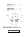
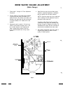
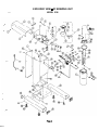
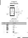
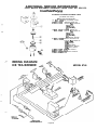
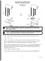
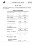
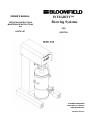
OWNER'S MANUAL
OPERATING INSTRUCTIONS
MAINTENANCE INSTRUCTIONS
and
INTEGRITY™
Brewing Systems
FOR
PARTS LIST
ICED TEA
70473
8746-M
BLOOMFIELD INDUSTRIES
2 ERIK CIRCLE, P.O. BOX 280
VERDI, NEVADA 89439
FAX (800) 356-5142
INDEX
INTRODUCTION TO THE UNITS ............................................……………. ...3
UNIT SET UP ..................................................................................………..…3& 4
BREWING OF TEA..................... ..................... .........................……………....4
TEABREWERADJUSTMENTS……………………………………………………4
TIMER/VOLUME ADJUSTMENT
BREWER WATER VOLUME ADJUSTMENT……………………………………5
RATIO CHANGE
PARTS LIST .................................... ............................................……………..6 & 7
EXPLODED VIEW OF BREWING UNIT .........................................……………8
EXPLODED VIEW, DISPENSER UNITS………………………………………….9
PARTS LIST, DISPENSER UNITS.......... .......................................……………9
SOLENOID EXPLOSION & PARTS LIST ......................................……..……..10
WIRING DIAGRAM................... ............. .....................................……………..10
WARRANTY .................................... ......................................………………….11
The INTEGRITY BREWERS have been designed with adjustment flexibility to cover a wide
spectrum of customer needs. Adjustments on the running thermostat and inlet timer are
simple adjustments easily accomplished by the purchaser, but NOT COVERED UNDER
ANY WARRANTY SERVICE AGREEMENT. Brewers must be installed in accordance with
installation instructions in the owner's manual for the warranty to be valid.
WARNING:
DO NOT PLUG IN OR ENERGIZE THIS UNIT
UNTIL INSTALLATION INSTRUCTIONS ARE READ
AND FOLLOWED.
PAGE 2
INTRODUCTION TO THE UNITS
This manual covers the six (6) gallon tea brewer and the six (6) gallon tea dispenser.
1. The Model 8746 is the tea brewing section
only and does not have a storage and/or dispensing reservoir as part of the unit.
2. The Model 8806 is the six (6) gallon stainless
steel reservoir to hold the finish brew.
All brewers are shipped from the factory with:
1.
2.
3.
4.
A Stainless Steel Brew Funnel.
A Wire Grid to support the filter paper and
A 25 pack of Filter Papers, and
A Water Line Filter.
Electrical Requirements:
Plumbing Requirements:
Unit requires a power source capable of supplying:
115 Volt, AC., 60 Hertz, Single Phase, 15 Amp.
Service.
Unit must be installed on a water line with a flowing
pressure between 20 PSI and 90 PSI. If water
pressure does not fall into this range or varies
greatly a pressure regulator should be installed
in the water supply line.
The unit is shipped from the factory with a 3-wire,
2-pole polarized power cord and cap attached.
SET UP
1. Carefully remove brewer and tea reservoir
from cartons.
6. Place reservoir under brewer.
7. Press momentary brew switch, to initiate
brewing cycle.
2. Set brewer in operating location and level,
using adjustable legs.
NOTE: Water will immediately begin to
flow from dilute water spout
3. Connect water line to 1/4” flare fitting on
back of unit. Turn on water and check for
leaks.
CAUTION: During this initial fill cycle, check
level of water in reservoir. Before initiating
another brew cycle, the reservoir must be
emptied to prevent overfilling and flooding.
4. Make sure tank heater switch on front panel
is in OFF position. Bottom portion of switch
rocker should be pressed in.
8. Repeat brewing cycles until water begins to
flow from spray disc.
5. Plug unit into 110-120 Volt grounded outlet,
fused at 15 Amps.
Page 3
9.
After end of final cycle, turn tank heater
switch to ON position - top portion of
switch rocker pressed in.
10.
When tank water is up to proper temperature, the green READY TO BREW light will
be lit.
12.
NOTE: During the initial heatup, some
water will drip from spray disc.
This is normal.
Discard water in six gallon dispenser, place
brew-through cover on dispenser then reposition
empty dispenser on brewer.
13.
Place filter and tea in brew chamber. Slide brew
chamber into place on brewer.
14.
Brewer is now ready for brewing tea.
7
11. Discard all water in reservoir and brew one (1)
additional cycle. CAUTION! Water dispensed from
spray disc will be HOT! Watch out for splashing.
If water level needs to be adjusted, see tea brewer
adjustments.
BREWING
1.
Place filter paper in brew chamber and add
tea. Slide brew chamber into rails, pushing
it to full back stop location.
5.
2. Check to see that reservoir with cover is properly located to accept dilute water spout
flow and brew chamber drain flow.
3.
Press brew switch to initiate brewing cycle.
4.
Dilute water will begin to flow immediately
into reservoir. Brewed tea will begin to flow
from brew chamber in about 20 to 30
seconds, and continue for approximately 10 to
12 minutes. Make sure drip-out is complete
before removing brew chamber.
If for any reason there is a need to stop the
brewing cycle before its completion, press the
“Brew Stop” switch. This stops water flow to the
brew chamber and the flow from dilute water
spout. The timing cycle is also cancelled and
timer resets to start.
6. Check level in reservoir - finished brew should
be approximately 1” from top edge.
7.
Brewed tea is now ready for use. If a change in
strength is desired, add or reduce tea, to taste .
preference and continue for approximately 10 to 12
minutes. Make sure drip-out is complete before
removing brew chamber.
TEA BREWER ADJUSTMENTS
The brewer is factory adjusted to produce six (6)
gallons of tea in a 1-5 brew to dilute water ratio.
Should it become necessary to adjust for total
volume, follow these steps below.
3. To brew more tea, turn knob slightly clockwise; to
brew less, turn slightly counterclockwise.
4.
TIMER ADJUSTMENT
(Total Volume Change)
Normal delivery should be six (6) gallons (766
ounces) of water.
1. Unplug unit.
2. Remove four (4) screws (2 on each side of cover)
lift off cover to expose timer.
Plug unit in and cycle unit. Check for required
volume - repeat if needed, until desired volume
is attained. Replace cover on brewer.
5.
Page 4
Do not readjust setting of needle valve!
BREW WATER VOLUME ADJUSTMENT
(Ratio Change)
1.
4. Water flow from spray disc and dilute spout
should be measured separately to determine
that the desired ratio has been achieved.
Follow steps 1 through 4 in Timer Adjustment
Procedure.
2. Turn the handle of the needle valve clockwise
IN (facing the valve stem and handle) to increase the ratio. This causes more water to be
diverted to the dilute flow, and less to the brew.
A counter-clockwise OUT rotation will do the
opposite.
NOTE: If flow from spray disc is very weak and
slow in starting, the ratio adjustment made is
starving the brew water flow.
If, however, water flows from the vent tube,
located next to the spray disc assembly, then
the ratio of water for brewing is too great. It is
advisable that the spray disc and vent tube be
viewed after an adjustment has been made.
3. Adjustments must be made in 1/4 turn increments to avoid drastic changes. One (1) full
turn in either direction is the maximum advised. Average factory setting is two full
turns counter-clockwise from a fully closed
position.
5. After desired adjustments have been made, a
complete brew should be made to insure
quality of finished product.
TOP VIEW WITH
COVER REMOVED
- THERMOSTAT
NEEDLE VALVE
FOR BREW RATIO CHANGE
HIGH LIMIT
- CONTROL
SOLENOID
VALVE ADJUSTMENT
FRONT OF BREWER
Page 5
REPLACEMENT PARTS LIST - OF BREWING UNIT
MODEL 8746
REF. NO.
1
2
3
4
6
7
8
9
10
11
12
13
14
15
16
17
19
20
21
1
23
24
25
26
27
28
29
30
31
32
33
34
35
36
37
38
39
40
41
42
44
45
46
47
49
50
PART NO.
DESCRIPTION
8543-52
8746-12
7200-6X
8043-5
8043-47
8543-69
#08x3x8 B.PN.P.SS
BASIN TOP WELDED
#O8-32 X 5/16 PN.P.SS
HOLD DOWN STRAP ASSY
#10-32 X 1 PN.P.SS
SHORTY BUSHING-HEYCO
TUBE, CONNECTOR
WATER OUTLET TUBE
SPRAY ELBOW
12 MINUTE TIMER 120V
BASIN WELDED ASSY
WIRE RACK
#1O-32 X 5/16 HEX HEAD
BASKET HANDLE
BREW CHAMBER STAMPED
SPRAYHEAD GASKET
SPRAYER DISC
PILOT LT. GREEN, 125V
BREW SWITCH, ROCKER
SWITCH, MOMENTARY NC
SWITCH, LIGHTED 12OV
TINNERMAN NUT
BODY WELDED ASSY
WATER SPOUT ASSY
MALE HOSE BARB FTG.
HOSE 1-1/2” LONG
FTG. NYLON Y 1/4 X 3/16
SPOUT CONN. HOSE 3#
NUT 7/16-20 X 1/8
UNION 1/4X 1/4M FLR.
WASHER-RESTRICTOR
NEEDLE SEAT VALVE
TANK INLT. TUBE ASSY
PIPE TEE
1/4 x 1/8 FPT. REDUCER
VENT TUBE
VENT TUBE
SOLENOID VALVE, 12OV
CONNECTOR
TUB. ASSY. VALVE INLT
WATER TANK, 6 GAL TEA
NUT, 1/2-24
WASHER-BACK-UP
OUTLET ELBOW ASSY
#8-32 HEX ACORN NUT
FILL TUBE ASSEMBLY
HTG. ELEM, 12OV, 1675W
S.S. WASHER
GASKET, FILL TUBE
8746-38
8043-13
8746-5 1
8746-13
8706-9
8707-3
8707-2
88 12-760
8543-42
8543-44
8718-31
8707-28
8812-79
8707-34
8543-23
8746-22
8746-16
88 12-56
8812-15
88 12-54
8746-59
8710-10
88 12-57
8810-70
851 4-26
8746-52
8812-55
8596-1240
8706-20
8043-15
8541-120
8706-160
8746-50
8746-34
7510-22
8812-70
8812-41
8043-506
8746-36
9102-9
8551-53
8942-33
Page 6
REPLACEMENT PARTS LIST
REF. NO.
51
52
53
54
55
57
59
60
61
62
63
65
66
67
68
69
70
71
72
73
74
75
76
77
(continued)
PART NO.
DESCRIPTION
8043-30
8710-10
8043-12
8043-28
8512-41
8512-51
88 12-34
8043-83
8746-28
8746-21
8942-92
8746-30
D 20002-3
8033-56
8033-55
88 12-47
8746-27
8746-29
35-210
8942-48
8812-73
8812-80
7506-39
3-100
HTG ELEMENT GASKET
NUT 7/16-20 X 1/8
TANK COVER GASKET
NUT, HEX /2-20 2B
SEAL WASHER
THERMOSTAT - R. SHAW
TANK COVER. WELDED ASSY
HI-LIMIT THERMOSTAT
LEG (LEFT)
BACK PANEL
NUT, #8-32 KEPS HEX
TEA 6 G STAND BASE
#10-32 X 5/16 PN.P.SS
LEG LEVELER CAP
LEG LEVELER
FITTING, NYLON Y3/16
END CAP FOR LEG
LEG (RIGHT)
CORD, GRIP, HEYCO LG
CORD & CAP - (12OV)
BREW BASKET CLIP
BREW CHAMBER ASSY
#8-32 X 1/2
SCREW 6-32 X 1/4 R.H.
ITEMS NOT SHOWN
PART NO.
DESCRIPTION
8747-8
8541-120JS
8541-120KS
BASIN FRONT LABEL (LUZIANNE)
SOLENOID REPAIR KIT
SOLENOID OVERHAUL KIT
Page 7
EXPLODED VIEW - OF BREWING UNIT
/--
MODEL 8748
EXPLODED VIEW
FOR
RESERVOIR AND DISPENSER
SECTIONS OF MODEL NO. 8808
‘1’
9
d
IO
1
2
85
MODEL NO. 8806
Model Without Slght Glass
REPLACEMENT PARTS LIST
PART NO.
DESCRIPTION
1
6600-50
Nut
2
8600-28
Flat Washer
3
6600-12
Nylon Washer
4
6600-6
Siynk
5
6600-15
Faucet ONLY, Plastic
6
6700-25 L
Seat Cup
7
6600-26
“c” Ring
6
6600-27
Wing Nut
9
6942-33
Gasket
10
6606-l
VS%l
11
6606-5
ClY4er
12
66061
Label (“Luzianne” _ not shown)
REF NO.
Pago 9
ADDITIONAL SERVICE INFORMATION
COLD WATER ENTRANCE SOLENOID VALVE PART NO. 8541-120
,ton*irtr Of hl”F and Flow Control,
SOLENOID VALVE REPLACEMENT PARTS
(For Black Coil Valve)
INo Kit Parts Sold Separately)
(1) 8541.120CS Coil Assembly 120V.
(2) 8541-120K
Solenoid Repair Kit
Vacuum Pat consists of:
(2A) Spring
(28) Plunger
(2C) Seal Ring
(3) 8541-120JS Solenoid Repair Kit
Vacuum Pat consists of:
(2A) Spring
(28) Plunger
(2C) Seal Ring
(20) Service Wrench
(4) 8541-120KS Solenoid Overhaul Kit
Vacuum Pat consists of:
@A) Spring
(28) Plunger
(2C) Seal Ring
(20) Service Wrench
(3A) Flow Control
(5) 8541.12OF
(3A) Flow Control
(6) 8541-120WS (2D) Service Wrench
WIRING DIAGRAM
ICE TEA BREWER
MODEL 8746
Page 10
WARRANTY
BREWER WARRANTY IS VOID IF:
For a period of one (1) year from date of installation, all defective parts on Bloomfield equipment
will be replaced free of charge, providing parts did
not become defective through accident, neglect,
improper installation, mishandling or damage in
transit. The service necessary to replace these
defective parts will also be free of charge, provided this service is performed by an authorized
BLOOMFIELD service station, wherever authorized service is available.
Other than genuine Bloomfield replacement parts
are used.
Brewer is plugged into voltage other than specified on serial plate.
Tank heating element is energized before water
tank is filled.
Recommended Bloomfield servicing procedures
are not followed.
How to OrderIndividual users and owners must order replacement parts thru their distributors or the local
authorized service station.
Terms - Prices, terms, designs, materials,
weights, specifications and dimentions for equipment or parts are subject to change without
notice.
Service Information - To obtain service
assistance in addition to that contained
in this manual, call Bloomfield’s toll free
number (800) 621-8556.
Be prepared to give the Model and Serial Numbers
of your brewer, as well as the problem and the
trouble-shooting steps already taken, to the service technician when calling for assistance.
=BLOOMFIELD
BLOOMFIELD INDUSTRIES
2 ERIK CIRCLE
P.O. BOX 280
VERDI, NV 89439
FAX (800) 358-5142
PRINTEO IN U.S.A.
page 11
-
INSTALLATION INSTRUCTION
FOR BASE EXTENDER KIT #83334
FOR MODEL 8748
TEA BREWER
h
1
/
2
FIGURE A
ELECTRICAL SHOCK HAZARD: Turn off the Tank Heater Switch and disconnect
- *
power supply to Brewer before removal of any panel. Electrical shock will cause
death or serious Injury.
Wait until the water in the tank has cooled down to room temperature
before Installing this Kit. Failure to comply will cause severe burns.
CAUTION:
STEP 1: Remove the Screws from the Back Panel (ITEM 1). Remove the Back Panel. (FIG A)
STEP 2: Drain Tank.
STEP 3: Set the Brewer on It’s side and remove the Bottom Base and Legs (ITEM 2). (FIG A)
STEP 4: Locate the Base Extender (ITEM 4) and the Speed Nuts (ITEM 3) included in the Kit.
Push the Speed Nuts onto the top and bottom flanges at each hole location. (FIG B)
STEP 5: Orient the Base Extender (ITEM 4) with the seam to the rear, the Bottom Base (ITEM 5)
and the Bottom Panel (ITEM 6) included in the Kit as shown on the exploded view (FIGURE B).
Make sure all the holes line up. Mount the Extender first, then the Base and Bottom Plate with
the Screws included in the Kit.
.
STEP 6: Replace the Back Panel (ITEM 1).
-
FOLLOW THE INITIAL INSTALLATION INSTRUCTION IN THE 8746 MANUAL FOR PROPER BREWING.
12
Part Number 73332