1
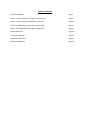
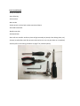
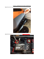
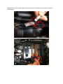
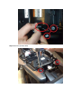
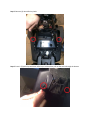
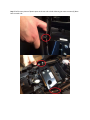
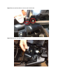
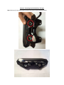
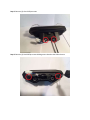
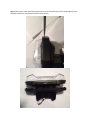
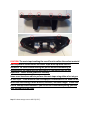
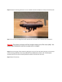
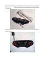
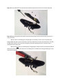
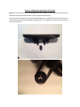
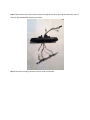
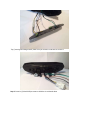
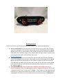
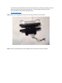
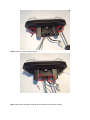
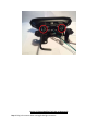
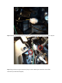
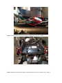
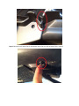
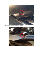
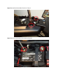
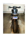
Lupus Lights
LL001 – 2014 Yamaha FZ-09 Integrated Tail Light
Installation Manual
Rev 2.0
March 29, 2014
TABLE OF CONTENTS
Tools You Will Need
Page 3
Section 1: Removing Stock Tail Light from Motorcycle
Page 4
Section 2: Removing Stock LED PCB from Tail Light
Page 12
Section 3: Adding Lupus Lights PCB to the Tail Light
Page 19
Section 4: Placing Modified Tail Light on Motorcycle
Page 25
General Disclaimer
Page 32
Limitation of Liability
Page 32
Legality of Product Use
Page 32
Warranty and Returns
Page 32
Tools You Will Need
-Phillips Screwdriver
-4mm Allen Key
-10mm socket
-8mm socket
-Socket wrench to drive both sockets mentioned above
-Flat Head Screwdriver
-Needle-nose plier
-Preheated Oven
-Oven-safe non-metallic surface to place tail light assembly on (wood, silicon baking sheet, etc)
-Camera (to take before and after pictures and send to us so we can post them on our website)
-Sealant (refer to the sealing procedure on page 7 for possible options)
Section 1: Removing Stock Tail Light from Motorcycle
Step 1: Remove the seat
Step 2: Before dealing with electricity make sure you disconnect the battery! ☠
Step 3: Disconnect the tail light signal connectors from the stock lamps (grey and black connectors
shown below)
Step 4: Remove (2) 10mm bolts
Step 5: Remove (2) 4mm Allen key bolts
Step 6: Press in (2) push clips with 4mm Allen key to release then pull out the entire through the bottom
Step 7: Pull the two pieces of plastic apart on the rear tail on both sides to give room to access (4) 8mm
bolts on each side
Step 8: Remove (4) 8mm bolts to remove seat lock bracket
Step 9: Remove the seat lock bracket
Step 10: Remove (2) 10mm nuts holding tail light assembly bracket on
Step 11: Carefully remove the bracket so that disconnecting the white connector is easier.
Step 12: Unplug white connectors (TIP: Depress tab with flathead screwdriver and pull with needle nose
pliers)
Step 13: Remove tail light from the motorcycle
Section 2: Removing Stock LED PCB from Tail Light
Step 1: Remove (2) 4mm Allen bolts to remove the metal tail light assembly bracket
Step 2: Remove (2) silver Phillips screws
Step 3: Remove (2) black Phillips screws holding outer shroud to the LED enclosure
Step 4: Remove the outer black housing from the inner one by pressing in all the (6) tabs gently with a
flathead screwdriver (See picture below for tab locations)
CAUTION: The next steps involving the use of heat to soften the sealant material
used to prevent condensation and water vapor build up inside the LED
enclosure. Be careful when heating the plastic because overheating or
overexposure can cause physical deformities in the plastic that are not
repairable. Please follow guidelines carefully.
Some users have been able to perform the next steps using either a hot air gun
or hair dryer. These methods can be employed in substitute of the oven but we
found that the heating is more difficult, less even, and takes longer. Please feel
free to attempt these methods if you do not feel comfortable placing your tail
light assembly into an oven.
Step 5: Preheat empty oven to 260°F [127°C].
Step 6: Place the remaining enclosure on a non-metallic container and place on the top rack of the oven.
Step 7: Turn the oven heating element off and allow the enclosure to sit in the oven for 15 minutes
Warning: The plastic enclosure will be hot when taken out of the oven (duh). Use
some kind of protection such as an oven mitt or a towel.
Step 8: Test the strength of the sealant by pulling the clear lens from the plastic enclosure. If the sealant
is still too strong place back in the oven and bake for an additional 5 minutes. (TIP: Carefully apply
outward pressure unto the 4 tab with flathead screwdriver and pull the clear lens)
Step 9: Retest if necessary.
Step 10: After separating the two pieces make sure that no sealant is left on the outside surfaces of the
lens or enclosure plastic. Once the sealant cools it will be very strong and almost impossible to remove
without reheating.
Step 11: After the enclosure has cooled, use a Phillip’s screwdriver to remove the 2 screws holding the
LED PCB to the enclosure.
Step 12: Pull the LED PCB from the enclosure and disconnect the connector on the back of the PCB.
Step 13: Remove the grommet and other side of the harnessing from the plastic harness (there are 2
ways to do this):
A) If you plan on reinstalling this tail light again in the future, do not cut the connector off!
Using needle-nose pliers, press in the tabs on each pin and pull it out of the connector block. This way
the grommet and wires can come out through the enclosure opening while the connector block is
removed from the other side.
B) If you do NOT plan on reinstalling this tail light again, simply cut the connector block off and
pull out the wires and grommet. (The wires can always be re-installed later through soldering or crimp
connectors if needed).
Section 3: Adding Lupus Lights PCB to the Tail Light
Step 0: TIP: If you’d like to reuse the OEM grommet, you will have to “gut” it to allow you to pass the
connectors through. We used an Exact-O knife to get the desired result.
If you don’t want to spend the time gutting the OEM grommet, simply fill the hole that the grommet
leaves with sealant material during the resealing process. This makes sure moisture cannot enter the
back of the enclosure.
Step 1: Route the wiring harness and connectors through the enclosure opening and make sure none of
them will get pinched when attaching the board.
Step 2: Connect the mating connectors that fit inside the assembly
Tip: If reusing the OEM grommet, make sure you reinsert it and twist to secure it!
Step 3: Screw in (2) black Phillips screws to hold the circuit board down
Resealing Procedure
There are a few ways to reseal the LED lens to the enclosure. They are described as follows:
A. Use of an RTV Silicon: Place the two halves of the enclosure on the top rack of the preheated
oven set to 260 degrees F for 10 minutes. Please make sure the oven heating element is turned
off when the enclosure is placed inside the oven. Remove the pieces from the oven and apply a
bead of RTV silicon inside the crevice of the enclosure where the black sealant is located. Firmly
insert the plastic lens back into the enclosure and let cool.
Permatex Black Silicon
B. Use of stock sealant: Place the two halves of the enclosure on the top rack of the preheated
oven set to 260 degrees F for 10 minutes. Please make sure the oven heating element is turned
off when the enclosure is placed inside the oven. Remove the pieces from the oven and firmly
insert the plastic lens back into the enclosure and let cool. This uses the sealant already placed
in the enclosure but may lead to condensation and water vapor inside the lens in the future if
the sealant has gaps in it.
C. Use of Butyl Rubber Glue: This is the method we employ at Lupus Lights whenever we
perform an LED board swap. The rubber glue has almost a dough-like consistency. Simply take
a long piece and roll it until it is about 1/8” in diameter. Fill the crevice in the enclosure with the
rolled out strip. Place the two halves of the enclosure on the top rack of the preheated oven set
to 260 degrees F for 10 minutes. Please make sure the oven heating element is turned off when
the enclosure is placed inside the oven. Remove the pieces from the oven and firmly insert the
plastic lens back into the enclosure and let cool. This uses a high performance sealant
recommended for head and tail light applications.
OCI Butyl Rubber Glue
Step 4: Route wires through external enclosure and snap it back onto lens assembly
Step 5: Screw in (2) black Phillips screws holding the outer enclosure to the lens assembly
Step 6: Screw in (2) silver Phillips screws
Step 7: Route wires through tail light bracket and attach (2) 4mm Allen screws
Section 4: Placing Modified Tail Light on Motorcycle
Step 1: Plug in the center white running/brake light connector.
Step 2: Reattach the tail light to the rear of the motorcycle using the bolts removed from Sec. 1: Step 10
Step 3: Plug in both turn signal connectors (they are color coded so just match the colors of the
connectors you have been shipped)
Step 4: Reinstall the seat lock bracket using the (4) 8mm bolts from Sec 1: Step 8
Step 5: Reinsert the two pieces of plastic on both sides of the rear tail (reverse of Sec 1: Step 7)
Step 6: Reinsert the (2) push clips on the bottom side of the rear tail (reverse of Sec 1: Step 6)
Step 7: Reinstall (2) 4mm Allen key bolts from Sec 1: Step 5
Step 8: Reinstall (2) 10mm bolts from Sec 1: Step 4
Step 9: Reconnect the battery to the electrical system.
Step 10: Place the seat back onto the motorcycle
Step 11: Turn on the motorcycle, test the operation of running lights, brake lights, and turn signals.
Step 12: Pat yourself on the back… you did it! Enjoy your awesome integrated LED tail light!
We would love to get feedback and installation photos! Please send any comments or critiques on how
we can make this process easier and send some completed pictures so we can add them to the website.
Thank you again for supporting this project and we hope that you get to enjoy your new lights for many
future riding seasons!
General Disclaimer
Please read all instructions carefully before installing this device on your motorcycle. The content in this
manual is for informational purposes only. Lupus Lights makes no representations or warranties with
respect to the accuracy or completeness of the content of this document. Lupus Lights reserves the
right to make changes to this document, product specifications, and product descriptions at any time
without prior notice and does not make any commitment to update the information contained herein.
The user of this product must be aware that this product is not approved for use in any critical
application where failure may result in personal injury or death. In other words, USE THIS PRODUCT AT
YOUR OWN RISK. IF YOU DO NOT UNDERSTAND IT, DO NOT USE IT.
Limitation of Liability
You understand and agree at the author(s) of this manual and any of its subsidiaries or affiliates shall in
no event be liable for any direct, indirect, incidental, consequential, or exemplary damages that may
come from following the instructions provided herein. The above limitation shall apply whether or not
the author(s) of this manual has been advised of or should have been aware of the possibilities of such
damages.
Legality of Product Use
This product DOES NOT meet DOT requirements for street legal tail lights and should only be used for
recreational off-road activities.
Warranty and Returns
This product carries a 90 day parts and labor warranty. If the unit is mechanically or electrically
defective, you may send it in to Lupus Lights for repair or replacement. Any physical modifications to
the unit or supplied harnessing WILL COMPLETELY VOID ANY WARRANTY. The user agrees to pay
shipping costs to send the unit to Lupus Lights in the instance of a warranty claim. The user also agrees
to properly package the unit as to not cause any damage in transit. Lupus Lights is not responsible for
the unit until it is physically received, so the user may want to consider shipping insurance or delivery
confirmation. Lupus Lights will pay for return shipping to the customer once a repair or replacement is
completed and the return has been approved by Lupus Lights through a written email.
To submit a warranty request, please contact [email protected]