1
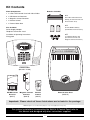
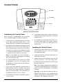
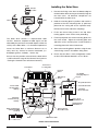
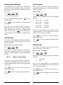
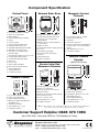
Control Panel
Zone LEDs
1
2
3
4
FIRE
TAMPER
ZONE
5
6
Status LEDs
1
2
3
4
5
6
7
8
9
0
Keypad
ESC
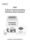
External view of Control Panel
6.
Positioning the Control Panel
Control Panel will need connecting to a convenient
When choosing a suitable location for the Control
telephone point.
Panel, the following points should be considered.
1.
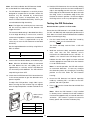
If the telephone voice dialler is to be used then the
7.
The Control Panel should be located in a position
Do not locate the Control Unit closer than 1m to
any large metallic object, (e.g. mirrors, radiators,
out of sight of potential intruders and in a safe
etc) as this may affect the radio range of the
location, but easily accessible for system operation.
Control Panel.
2.
The Control Panel should be mounted on a sound
flat surface to ensure that the rear tamper switch
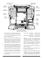
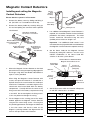
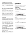
Installing the Control Panel
on the Control Panel is closed when the Panel is
1.
mounted. The Control Panel should be mounted
at a convenient height of between 1.5 and 2m and
panel and open the cover. The cover is hinged
in a position where it will be seen each day.
along the bottom edge.
2.
Note: If small children are in the household, a
further consideration should be given to keeping
3.
mark the positions of the four fixing holes.
be positioned such that the Exit/Entry tone
Remove the Panel and drill four 5mm holes and fit
(emitted by the Control Panel) can be heard from
the 25mm Wall Plugs.
Note: The wall plugs supplied with the product are
The Control Panel should be mounted within a
not suitable for plasterboard walls, if mounting the
protected area so that any intruder cannot reach
Control Panel onto plasterboard use proprietary
the Control Panel without opening a protected
wall plugs.
door or passing through an area protected by a
Important: Do not drill the fixing holes with the
PIR Detector when the system is armed.
5.
Hold the Control Panel in position on the wall and
It is recommended that the Control Panel should
outside the property.
4.
Unclip and remove the two back-up batteries on
either side of the panel.
the units out of their reach.
3.
Undo the two captive fixing screws on top of the
Control Panel in position; as the resulting dust and
The Control Panel must be located within reach of
vibration may damage the Control Panel’s internal
a mains socket.
components and invalidate the guarantee.
7