1
OPERATING INSTRUCTIONS
Printer Reference
Read this manual carefully before you use this product and keep it handy for future
reference.
For safety, please follow the instructions in this manual.
RICOH COMPANY, LTD.
15-5, 1 chome, Minami-Aoyama, Minato-ku, Tokyo
Telephone: Tokyo 3479-3111
U.S.A.
RICOH CORPORATION
5 Dedrick Place
West Caldwell, New Jersey 07006
Phone: +1-973-882-2000
Spain
RICOH ESPAÑA S.A.
Avda. Litoral Mar, 12-14,
08005 Barcelona
Phone: +34-(0)93-295-7600
The Netherlands
RICOH EUROPE B.V.
Groenelaan 3, 1186 AA, Amstelveen
Phone: +31-(0)20-5474111
Italy
RICOH ITALIA SpA
Via della Metallurgia 12,
37139 Verona
Phone: +39-(0)45-8181500
United Kingdom
RICOH UK LTD.
Ricoh House,
1 Plane Tree Crescent, Feltham,
Middlesex, TW13 7HG
Phone: +44-(0)181-261-4000
Germany
RICOH DEUTSCHLAND GmbH
Mergenthalerallee 38-40,
65760 Eschborn
Phone: +49-(0)6196-9060
France
RICOH FRANCE S.A.
383, Avenue du Général de Gaulle
BP 307-92143 Clamart Cedex
Phone: +33-(0)1-40-94-38-38
Model number: G024–17
Printed in Japan
UE USA G024-8637
Hong Kong
RICOH HONG KONG LTD.
23/F., China Overseas Building,
139, Hennessy Road,
Wan Chai, Hong Kong
Phone: +852-2862-2888
Singapore
RICOH ASIA PACIFIC PTE.LTD.
260 Orchard Road,
#15-01/02 The Heeren,
Singapore 238855
Phone: +65-830-5888
RICOH COLOR LASER AP505 OPERATING INSTRUCTIONS
Overseas Affiliates
Introduction
This manual contains detailed instructions on the operation and maintenance of this machine. To get
maximum versatility from this machine all operators should carefully read and follow the instructions in
this manual. Please keep this manual in a handy place near the machine.
Please read the Safety Information before using this machine. It contains important information related
to USER SAFETY and PREVENTING EQUIPMENT PROBLEMS.
Power Source
120 V, 60 Hz, 10 A or more
Please be sure to connect the power cord to a power source as above.
Operator Safety:
This machine is considered a CDRH class I laser device, safe for office/ EDP use. The machine contains 10-milliwatt, 760 - 800 nanometer wavelength, GaAIAs laser diode. Direct (or indirect reflected)
eye contact with the laser beam might cause serious eye damage. Safety precautions and interlock
mechanisms have been designed to prevent any possible laser beam exposure to the operator.
Laser Safety:
The Center for Devices and Radiological Health (CDRH) prohibits the repair of laser-based optical unit
in the field. The optical housing unit can only be repaired in a factory or at a location with the requisite
equipment. The laser subsystem is replaceable in the field by a qualified Customer Engineer. The laser
chassis is not repairable in the field. Customer engineers are therefore directed to return all chassis
and laser subsystems to the factory or service depot when replacement or the optical subsystem is required.
Important
Parts of this manual are subject to change without prior notice. In no event will the company be liable
for direct, indirect, special, incidental, or consequential damages as a result of handling or operating
the machine.
Caution:
Use of controls or adjustment or performance of procedures other than those specified in this manual
might result in hazardous radiation exposure.
Do not attempt any maintenance or troubleshooting other than that mentioned in this manual. This machine contains a laser beam generator and direct exposure to laser beams can cause permanent eye
damage.
Two kinds of size notation are employed in this manual. With this machine refer to the inch version.
Ricoh shall not be responsible for any damage or expense that might result from the use of parts other
than genuine Ricoh parts in your Ricoh office product.
For good copy quality, Ricoh recommends that you use genuine Ricoh toner.
Note to users in the United States of America
Notice:
This equipment has been tested and found to comply with the limits for a Class B digital device, pursuant to
Part 15 of the FCC Rules. These limits are designed to provide reasonable protection against harmful interference in a residential installation. This equipment generates, uses and can radiate radio frequency energy
and, if not installed and used in accordance with the instructions, may cause harmful interference to radio
communications.
However, there is no guarantee that interference will not occur in a particular installation. If this equipment
does cause harmful interference to radio or television reception, which can be determined by turning the
equipment off and on, the user is encouraged to try to correct the interference by one more of the following
measures:
Reorient or relocate the receiving antenna.
Increase the separation between the equipment and receiver.
Connect the equipment into an outlet on a circuit different from that to which the receiver is connected.
Consult the dealer or an experienced radio/TV technician for help.
Warning
Changes or modifications not expressly approved by the party responsible for compliance could void the user's authority to operate the equipment.
Caution (in case of 100BaseTX environment):
Properly shielded and grounded cables (STP) and connectors must be used for connections to host computer (and/or peripheral) in order to meet FCC emission limits.
Declaration of Conformity
Product Name: Printer
Model Number: G024–17
Responsible party: Ricoh Corporation
Address: 5 Dedrick Place, West Caldwell, NJ 07006
Telephone number: 973-882-2000
This device complies with part 15 of FCC Rules.
Operation is subject to the following two conditions:
1. This device may not cause harmful interference, and
2. this device must accept any interference received,
including interference that may cause undesired operation.
Properly shielded cables must be used for connections to host computer (and/or peripheral) in
order to meet FCC emission limits.
Network interface cable with ferrite core must be used for RF interference suppression.
Note to users in Canada
Note:
This Class B digital apparatus complies with Canadian ICES-003.
Remarque concernant les utilisateurs au Canada
Avertissement:
Cet appareil numérique de la classe B est conforme à la norme NMB-003 du Canada.
In accordance with IEC 60417, this machine uses the following symbols for the main power switch:
a means POWER ON.
b means POWER OFF.
Copyright © 1999 Ricoh Co., Ltd.
Introduction
This manual contains detailed instructions on the operation and maintenance of this machine. To get
maximum versatility from this machine all operators should carefully read and follow the instructions in
this manual. Please keep this manual in a handy place near the machine.
Please read the Safety Information before using this machine. It contains important information related
to USER SAFETY and PREVENTING EQUIPMENT PROBLEMS.
Power Source
120 V, 60 Hz, 10 A or more
Please be sure to connect the power cord to a power source as above.
Operator Safety:
This machine is considered a CDRH class I laser device, safe for office/ EDP use. The machine contains 10-milliwatt, 760 - 800 nanometer wavelength, GaAIAs laser diode. Direct (or indirect reflected)
eye contact with the laser beam might cause serious eye damage. Safety precautions and interlock
mechanisms have been designed to prevent any possible laser beam exposure to the operator.
Laser Safety:
The Center for Devices and Radiological Health (CDRH) prohibits the repair of laser-based optical unit
in the field. The optical housing unit can only be repaired in a factory or at a location with the requisite
equipment. The laser subsystem is replaceable in the field by a qualified Customer Engineer. The laser
chassis is not repairable in the field. Customer engineers are therefore directed to return all chassis
and laser subsystems to the factory or service depot when replacement or the optical subsystem is required.
Important
Parts of this manual are subject to change without prior notice. In no event will the company be liable
for direct, indirect, special, incidental, or consequential damages as a result of handling or operating
the machine.
Caution:
Use of controls or adjustment or performance of procedures other than those specified in this manual
might result in hazardous radiation exposure.
Do not attempt any maintenance or troubleshooting other than that mentioned in this manual. This machine contains a laser beam generator and direct exposure to laser beams can cause permanent eye
damage.
Two kinds of size notation are employed in this manual. With this machine refer to the inch version.
Savin shall not be responsible for any damage or expense that might result from the use of parts other
than genuine Savin parts in your Savin office product.
For good copy quality, Savin recommends that you use genuine Savin toner.
Note to users in the United States of America
Notice:
This equipment has been tested and found to comply with the limits for a Class B digital device, pursuant to
Part 15 of the FCC Rules. These limits are designed to provide reasonable protection against harmful interference in a residential installation. This equipment generates, uses and can radiate radio frequency energy
and, if not installed and used in accordance with the instructions, may cause harmful interference to radio
communications.
However, there is no guarantee that interference will not occur in a particular installation. If this equipment
does cause harmful interference to radio or television reception, which can be determined by turning the
equipment off and on, the user is encouraged to try to correct the interference by one more of the following
measures:
Reorient or relocate the receiving antenna.
Increase the separation between the equipment and receiver.
Connect the equipment into an outlet on a circuit different from that to which the receiver is connected.
Consult the dealer or an experienced radio/TV technician for help.
Warning
Changes or modifications not expressly approved by the party responsible for compliance could void the user's authority to operate the equipment.
Caution (in case of 100BaseTX environment):
Properly shielded and grounded cables (STP) and connectors must be used for connections to host computer (and/or peripheral) in order to meet FCC emission limits.
Declaration of Conformity
Product Name: Printer
Model Number: G024–17
Responsible party: Ricoh Corporation
Address: 5 Dedrick Place, West Caldwell, NJ 07006
Telephone number: 973-882-2000
This device complies with part 15 of FCC Rules.
Operation is subject to the following two conditions:
1. This device may not cause harmful interference, and
2. this device must accept any interference received,
including interference that may cause undesired operation.
Properly shielded cables must be used for connections to host computer (and/or peripheral) in
order to meet FCC emission limits.
Network interface cable with ferrite core must be used for RF interference suppression.
Note to users in Canada
Note:
This Class B digital apparatus complies with Canadian ICES-003.
Remarque concernant les utilisateurs au Canada
Avertissement:
Cet appareil numérique de la classe B est conforme à la norme NMB-003 du Canada.
In accordance with IEC 60417, this machine uses the following symbols for the main power switch:
a means POWER ON.
b means POWER OFF.
Introduction
This manual contains detailed instructions on the operation and maintenance of this machine. To get
maximum versatility from this machine all operators should carefully read and follow the instructions in
this manual. Please keep this manual in a handy place near the machine.
Please read the Safety Information before using this machine. It contains important information related
to USER SAFETY and PREVENTING EQUIPMENT PROBLEMS.
Power Source
120 V, 60 Hz, 10 A or more
Please be sure to connect the power cord to a power source as above.
Operator Safety:
This machine is considered a CDRH class I laser device, safe for office/ EDP use. The machine contains 10-milliwatt, 760 - 800 nanometer wavelength, GaAIAs laser diode. Direct (or indirect reflected)
eye contact with the laser beam might cause serious eye damage. Safety precautions and interlock
mechanisms have been designed to prevent any possible laser beam exposure to the operator.
Laser Safety:
The Center for Devices and Radiological Health (CDRH) prohibits the repair of laser-based optical unit
in the field. The optical housing unit can only be repaired in a factory or at a location with the requisite
equipment. The laser subsystem is replaceable in the field by a qualified Customer Engineer. The laser
chassis is not repairable in the field. Customer engineers are therefore directed to return all chassis
and laser subsystems to the factory or service depot when replacement or the optical subsystem is required.
Important
Parts of this manual are subject to change without prior notice. In no event will the company be liable
for direct, indirect, special, incidental, or consequential damages as a result of handling or operating
the machine.
Caution:
Use of controls or adjustment or performance of procedures other than those specified in this manual
might result in hazardous radiation exposure.
Do not attempt any maintenance or troubleshooting other than that mentioned in this manual. This machine contains a laser beam generator and direct exposure to laser beams can cause permanent eye
damage.
Two kinds of size notation are employed in this manual. With this machine refer to the inch version.
Gestetner shall not be responsible for any damage or expense that might result from the use of parts
other than genuine Gestetner parts in your Gestetner office product.
For good copy quality, Gestetner recommends that you use genuine Gestetner toner.
Note to users in the United States of America
Notice:
This equipment has been tested and found to comply with the limits for a Class B digital device, pursuant to
Part 15 of the FCC Rules. These limits are designed to provide reasonable protection against harmful interference in a residential installation. This equipment generates, uses and can radiate radio frequency energy
and, if not installed and used in accordance with the instructions, may cause harmful interference to radio
communications.
However, there is no guarantee that interference will not occur in a particular installation. If this equipment
does cause harmful interference to radio or television reception, which can be determined by turning the
equipment off and on, the user is encouraged to try to correct the interference by one more of the following
measures:
Reorient or relocate the receiving antenna.
Increase the separation between the equipment and receiver.
Connect the equipment into an outlet on a circuit different from that to which the receiver is connected.
Consult the dealer or an experienced radio/TV technician for help.
Warning
Changes or modifications not expressly approved by the party responsible for compliance could void the user's authority to operate the equipment.
Caution (in case of 100BaseTX environment):
Properly shielded and grounded cables (STP) and connectors must be used for connections to host computer (and/or peripheral) in order to meet FCC emission limits.
Declaration of Conformity
Product Name: Printer
Model Number: G024–17
Responsible party: Ricoh Corporation
Address: 5 Dedrick Place, West Caldwell, NJ 07006
Telephone number: 973-882-2000
This device complies with part 15 of FCC Rules.
Operation is subject to the following two conditions:
1. This device may not cause harmful interference, and
2. this device must accept any interference received,
including interference that may cause undesired operation.
Properly shielded cables must be used for connections to host computer (and/or peripheral) in
order to meet FCC emission limits.
Network interface cable with ferrite core must be used for RF interference suppression.
Note to users in Canada
Note:
This Class B digital apparatus complies with Canadian ICES-003.
Remarque concernant les utilisateurs au Canada
Avertissement:
Cet appareil numérique de la classe B est conforme à la norme NMB-003 du Canada.
In accordance with IEC 60417, this machine uses the following symbols for the main power switch:
a means POWER ON.
b means POWER OFF.
Trademarks
Windows®, and Windows NT® are registered trademarks of Microsoft Corporation in the United States and/or other countries.
PostScript® is a registered trademark of Adobe Systems. Incorporated.
AppleTalk is registered trademarks of Apple Computer, Incorporated.
Other product names used herein are for identification purposes only and might
be trademarks of their respective companies. We disclaim any and all rights in
those marks.
Notes:
Some illustrations might be slightly different from your machine.
Certain options might not be available in some countries. For details, please contact your local dealer.
Notes:
The proper names of the Windows operating systems are as follows:
• Microsoft® Windows® 95 operating system
• Microsoft® Windows® 98 operating system
• Microsoft® Windows NT® Server network operating system Version 4.0
• Microsoft® Windows NT® Workstation operating system Version 4.0
i
Safety Information
When using your equipment, the following safety precautions should always be
followed.
Safety During Operation
In this manual, the following important symbols are used:
R WARNING:
Indicates a potentially hazardous situation which, if instructions are
not followed, could result in death or serious injury.
R CAUTION:
Indicates a potentially hazardous situation which, if instructions are not followed, may result in minor or moderate injury or damage to property.
ii
R WARNING:
• Connect the power cord directly into a wall outlet and never use an extension cord.
• Disconnect the power plug (by pulling the plug, not the cable) if the
power cable or plug becomes frayed or otherwise damaged.
• To avoid hazardous electric shock or laser radiation exposure, do not
remove any covers or screws other than those specified in this manual.
• Turn off the power and disconnect the power plug (by pulling the
plug, not the cable) if any of the following conditions exists:
• You spill something into the equipment.
• You suspect that your equipment needs service or repair.
• Your equipment's cover has been damaged.
• Do not incinerate spilled toner or used toner. Toner dust might ignite
when exposed to an open flame.
• Disposal can take place at our authorized dealer or at appropriate collection sites.
• If you dispose of the used toner containers yourself, dispose of them
according to your local regulations.
iii
R CAUTION:
• Protect the equipment from dampness or wet weather, such as rain, snow,
and so on.
• Unplug the power cord from the wall socket before you move the equipment. While moving the equipment, you should take care that the power
cord will not be damaged under the equipment.
• When you disconnect the power plug from the wall socket, always pull the
plug (not the cable).
• Do not allow paper clips, staples, or other small metallic objects to fall inside the equipment.
• Do not eat or swallow toner.
• Keep toner (used or unused) and toner cartridge out of reach of children.
• For environmental reasons, do not dispose of the equipment or expended
supply's wastes at a household waste a collection point. Disposal can take
place at our authorized dealer or at an appropriate collection site.
• Our products are engineered to meet the highest standards of quality and
functionality. When purchasing expendable supplies, we recommend using
only those specified by an authorized dealer.
• The inside of the machine could be very hot. Do not touch the parts with a
label indicating the “hot surface”. Otherwise, it could cause a personal burn.
• If you use this printer in a cold area, leave the printer on. Otherwise, severe
cold might damage sensitive components inside the printer.
iv
Energy Star Program
As an ENERGY STAR Partner, we have determined that this machine model meets the ENERGY STAR Guidelines for energy efficiency.
The ENERGY STAR Guidelines intend to establish an international energy-saving system for developing and introducing energy-efficient office equipment to deal with environmental issues, such as global warming.
When a product meets the ENERGY STAR Guidelines for energy efficiency, the Partner shall place the ENERGY STAR logo onto the machine model.
This product was designed to reduce the environmental impact associated with office
equipment by means of energy-saving features, such as Low-power mode.
❖ Low-power mode (Energy Save mode)
This printer automatically lowers its power consumption 60 minutes after the
last operation has been completed when the Energy Save mode is set to level
1. To exit Low-power (Energy Save) mode, press any key on the operation
panel. To change the setting of the Energy Save mode, see the “Getting Started”.
❖ Specifications
Lower-power mode
Power Consumption
45W or less
(Energy Save mode)
Default Time
60 minutes
-Recycled Paper
Please contact your sales or service representative for recommended recycled
paper types that may be used in this machine.
v
Manuals for Your Printer
Manuals for Your Printer
There are four manuals that describe the procedures separately for the installation of your printer and for the operation and maintenance of your printer and
its optional equipment.
To enhance safe and efficient operation of your printer, all users should read and
follow the instructions contained in the following manuals.
❖ Quick Installation Guide
Describes the procedures for installing your printer.
❖ Getting Started
Describes how to install software to enable users to print. Specifically, it describes installation of PostScript printer drivers, printer description files, and
other software provided on the CD-ROM that comes with the printer. It also
explains how to connect each user to the network.
❖ User's Guide
Provides an introduction to desktop color printing, how to print from various
computers and workstations, what you need to know about using the printer
in a networked environment, and how to use the software provided.
❖ Printer Reference (this manual)
Describes the procedures and necessary information on setting up and using
your printer and its optional equipment.
vi
How to Read this Manual
Symbols
In this manual, the following symbols are used:
R WARNING:
This symbol indicates a potentially hazardous situation which, if instructions
are not followed, could result in death or serious injury.
R CAUTION:
This symbol indicates a potentially hazardous situation which, if instructions
are not followed, may result in minor or moderate injury or damage to property.
* The statements above are notes for your safety.
Important
If this instruction is not followed, paper might be misfed, originals might be
damaged, or data might be lost. Be sure to read this.
Preparation
This symbol indicates the prior knowledge or preparations required before operating.
Note
This symbol indicates precautions for operation, or actions to take after misoperation.
Limitation
This symbol indicates numerical limits, functions that cannot be used together,
or conditions in which a particular function cannot be used.
Reference
This symbol indicates a reference.
[
]
Keys that appear on the machine's panel display.
Keys and buttons that appear on the computer's display.
{
}
Keys built into the machine's operation panel.
Keys on the computer's keyboard.
vii
TABLE OF CONTENTS
1. Getting Acquainted
Guide to the Printer ...................................................................................
Exterior-Front View .......................................................................................
Exterior-Rear View ........................................................................................
Interior ...........................................................................................................
Operation Panel ............................................................................................
Turning the Printer On and Off.................................................................
Turning On the Printer...................................................................................
Turning Off the Printer...................................................................................
1
1
3
4
5
6
6
6
2. Installing Options
Available Options ...................................................................................... 8
Installing the Memory Unit Type505 (DIMM) ........................................... 9
Installing the Printer Hard Disk Type505............................................... 11
Installing the Paper Feed Unit Type305................................................. 13
3. Paper and Other Media
Paper and Other Media Supported by this Printer ...............................
Paper Types and Sizes ...............................................................................
Precautions for Paper .................................................................................
Printable Area .............................................................................................
Loading Paper..........................................................................................
Loading Paper in the Paper Tray ................................................................
Loading Paper in the Bypass Tray ..............................................................
Sliding out the Output Tray Extender ..........................................................
15
15
20
24
25
25
27
28
4. Troubleshooting
Error & Status Messages on the Operation Panel................................
Printer Doesn't Print................................................................................
Other Printing Problems .........................................................................
Removing Misfed Paper..........................................................................
When the Message "REMOVE MISFEED FROM INPUT TRAY" Appears ....
When the Message "OPEN FRONT COVER REMOVE MISFEED" Appears ..
When the Message "REMOVE MISFEED FROM OUTPUT TRAY" Appears...
viii
29
32
35
38
39
39
40
Cleaning the Printer ................................................................................
Cleaning the Friction Pad ............................................................................
Cleaning the Charger ..................................................................................
Cleaning the Dust-proofing glass ................................................................
Replacing Consumables.........................................................................
Replacing the Toner Cartridge ....................................................................
Replacing the Photoconductor Unit.............................................................
Replacing the Fuser Oil Bottle and Ozone Filter.........................................
Replacing the Waste Toner Bottle and Charger .........................................
42
42
42
43
45
45
48
50
53
5. Appendix
Moving and Transporting the Printer ....................................................
Specifications ..........................................................................................
Mainframe ...................................................................................................
Options........................................................................................................
Consumables ...........................................................................................
55
56
56
59
60
INDEX........................................................................................................ 62
ix
x
1. Getting Acquainted
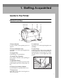
Guide to the Printer
Exterior-Front View
12 3 4
5
6
7
8
10
11
9
TFWX020E
1. Power Switch
8. Left Cover
Use this switch to turn printer power on
and off.
Open this cover when replacing the toner
cartridge.
2. Fuser Oil Bottle Cover
9. Inset Grips
Open this cover when replacing the fuser
oil bottle.
Hold the printer at the location indicated
in the illustration when transporting it.
Note that there are four grips, two on the
left side and two on the right side of the
printer.
3. Output Tray
Printed pages are stacked here.
4. Output Tray Extender
Pull out this extender when printing on
long paper.
5. Operation Panel
Contains keys for printer operation and a
panel display that shows the printer status.
6. Front Cover Release Button
Use this button to open the front cover.
TFWX030E
7. Front Cover
Open this cover when accessing the inside of the printer.
1
Getting Acquainted
10. Bypass tray
Use to print on to thick paper, OHP transparencies and adhesive labels in addition
to plain paper.
1
11. Paper Tray
Load paper into this tray for printing.
2
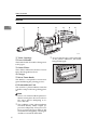
Guide to the Printer
Exterior-Rear View
2
1
1
3
4
5
6
1. Paper Exit Cover
Open this cover when removing misfed
paper at the fusing unit.
2. Ozone Filter
This filter reduces the amount of ozone
that is discharged into the air.
3. Ventilator
This hole allow air to circulate, preventing components inside the printer from
overheating.
Important
❒ Do not leave the ventilator obstructed or blocked. Doing so creates the danger of malfunction due
to overheating.
4. Back Plate
Remove to install some options.
5. Parallel Interface Connector
Plug the interface cable that connects the
printer to your computer into this connector.
Important
❒ Rating voltage of the parallel interface connector for the computer;
Max. DC 5V.
6. Network Interface Connector for
10BASE-T/100BASE-TX
7 8
9
TFWX040E
Plug the network interface cable for
10BASE-T/100BASE-TX that connects
the printer to the network into this connector.
Important
❒ Rating voltage of the network interface connector for 10BASE-T/
100BASE-TX; Max. DC5V.
7. Network Interface Connector for
10BASE5
Plug the network interface cable for
10BASE5 that connects the printer to the
network into this connector.
Important
❒ Rating voltage of the network interface connector for 10BASE5;
Max. DC12V.
8. Ventilator
This hole allow air to circulate, preventing components inside the printer from
overheating.
Important
❒ Do not leave the ventilator obstructed or blocked. Doing so creates the danger of malfunction due
to overheating.
9. Power Connector
Connect the power cord to this connector.
3
Getting Acquainted
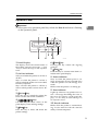
Interior
1
1
2
3
4
5
6
TFWX051E
1. Toner Cartridge
2. Fuser Oil Bottle
❒ Do not rotate the gear on the right side
of the printer. Otherwise, the inside
belt gets damaged.
This bottle holds oil used for fusing toner
to the paper.
3. Ozone Filters
These filters reduce the amount of ozone
that is discharged into the air.
4. Charger
5. Waste Toner Bottle
This bottle is a receptacle for waste toner
generated during the printing process.
6. Photoconductor Unit
This contains a photoconductor unit that
is used to compose the image being printed.
Note
❒ Screws are used to hold the photoconductor unit in place. Be sure to remove
the screws before attempting to remove the unit.
❒ The condition of the photoconductor
unit belt directly affects output appearance and quality. Always be careful to prevent the green film in this
unit from becoming dirty or damaged.
And do not touch the black belt.
4
TFWX060E
Guide to the Printer
Operation Panel
Important
❒ Never press any operation panel keys while the Data In indicator is flashing
on the operation panel.
1
23
1
4
On Line
Menu
Power
Enter
Cancel
Error
Data In
5 6
8
9
7
10
TFWS010E
1. Panel Display
6. {Cancel} key
The display shows the current status of
the printer and error messages. ⇒ P.29
“Error & Status Messages on the Operation
Panel”
Pressing this key cancels the ongoing
print job.
2. On Line indicator
7. {Enter} key
Press this key to execute menu items selected on the panel display.
Tells you whether the printer is on-line or
off-line.
Stays on while the printer is on-line (a
state in which the printer can receive data
from the computer).
Stays off when the printer is off-line (a
state in which printer cannot receive data).
8. Power indicator
3. {On Line} key
Lights up whenever any printer error occurs. A message describing the cause of
the error also appears on the panel display. ⇒ P.29 “Error & Status Messages on
the Operation Panel”
Press this key to switch the printer between on-line and off-line conditions.
4. {W}{U}{V}{T} keys
Use these keys to select values on the
panel display when making settings.
5. {Menu} key
Press this key to make and check the
printer settings.
Stays on while the printer power is on.
Stays off when the power is turned off or
while the printer is in the Energy Save
mode.
Blinks while the printer is warming up.
9. Error indicator
10. Data In indicator
Blinks while the printer is communicating via the network with the network
utility of client computers.
5
Getting Acquainted
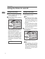
Turning the Printer On and Off
1
Turning On the Printer
Turning Off the Printer
A Make sure that the power cord is
A Confirm that the Data In and the
B Set the printer's power switch to
Note
❒ The Data In indicator blinks
while receiving and printing
data from the computer and remains lit when printing. Do not
turn off the printer while it is
blinking.
securely plugged into the wall
socket and the printer.
the On position.
Error indicators are off.
❒ When the Error indicator lights
up, a printer error has occurred.
Use the message that appears
on the operation panel to troubleshoot the problem.
TFWX130E
After turning on the printer, it
takes about eight minutes to warm
up before being able to print.
When the printer is turned on, the
Power indicator will blink repeatedly. Once it stops blinking and remains on, you will be able to send
data from the computer to the
printer. When the following message appears on the operation panel, the printer will be able to begin
printing.
READY
6
B Set the printer's power switch to
the Off position.
TFWX110E
The Power indicator turns off.
Note
❒ After printing, wait for about
two minutes before turning off
the printer. The printer uses this
time to maintain itself. Turning
off the printer immediately after
printing may, over time, reduce
the print quality.
2. Installing Options
R CAUTION:
• Make sure to turn off the printer and wait for about 30 minutes before in-
stalling options. Not waiting for the printer to cool down can result in a burn.
• It is recommended that at least two persons are used to lift the machine.
Otherwise, the machine might fall and cause personal injury.
• When lifting the machine, use the inset grips on both sides of the machine.
Otherwise, the machine might fall and cause personal injury.
• When you move the machine, unplug the power cord from the wall socket
to avoid a fire or an electric shock.
7
Installing Options
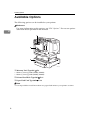
Available Options
The following options can be installed to your printer.
Reference
For more information on the options, see P.59 “Options”. Do not use options
other than those specified in this manual.
2
1
2
3
TFWX180E
1. Memory Unit Type505 ⇒ P.9
• Memory Unit Type505 (32MB) (DIMM)
• Memory Unit Type505 (64MB) (DIMM)
2. Printer Hard Disk Type505 ⇒ P.11
3. Paper Feed Unit Type305 ⇒ P.13
Note
❒ It is impossible to install more than two paper feed units to your printer at a time.
8
Installing the Memory Unit Type505 (DIMM)
Installing the Memory Unit Type505 (DIMM)
R CAUTION:
• Make sure to turn off the printer
and wait for about 30 minutes
before installing options. Not
waiting for the printer to cool
down can result in a burn.
Important
❒ The memory unit can be damaged
by small amounts of static electricity. Before touching it, touch something metal to discharge static
electricity from you.
A Turn
off the printer's power
switch and remove all cables and
cords from the printer.
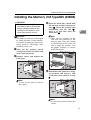
C Open the white tabs, which hold
the memory, to their widest position (A). Insert the memory unit
horizontally into the slot (B).
Push it in and then close the
white tabs (C).
2
Note
❒ There are two notches on the
side with the connector of the
memory unit. They are located
on the left and in the center. Be
sure to align the notches over
the guides correctly, as shown
in the illustration.
B Remove
screws and remove the
back plate.
TFWX190E
D Attach the back plate to its origiTFWX185E
nal position, and fasten it with
screws that were removed in step
B.
Note
❒ A coin can be used to remove
the screws.
TFWX195E
Note
❒ A coin can be used to fasten the
screws.
9
Installing Options
E Plug
the printer's power cord
back into the printer and the wall
socket. Turn on the printer's power switch.
F Print a configuration page to confirm that the memory unit is properly installed.
2
Reference
For more information on the
configuration page, see the
“Getting Started”.
Note
❒ If the memory unit is not properly installed, repeat steps A to F
again. If you fail again, contact
your sales or service representative.
10
Installing the Printer Hard Disk Type505
Installing the Printer Hard Disk Type505
R CAUTION:
• Make sure to turn off the printer
and wait for about 30 minutes
before installing options. Not
waiting for the printer to cool
down can result in a burn.
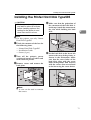
D Make sure that the projection of
the connector of the hard disk is
on the top. Attach the connector to
the slot while holding the hard
disk.
2
Note
❒ For this printer, use only Printer
Hard Disk Type505.
A Check the contents of the box for
the following items.
• Printer Hard Disk Type505
• Installation Guide
• Screws (3 pcs)
B Turn
off the printer's power
switch and remove all cables and
cords from the printer.
C Remove
screws and remove the
back plate.
TFWX600E
E Set the hard disk in the lower left
corner at the rear of the printer, as
shown in the illustration. Make
sure that the screw holes of the
hard disk align with the screw
holes of the printer. And fasten it
with the screws that are enclosed
in the box using the screw driver.
TFWX186E
TFWX610E
Note
❒ A coin can be used to remove
the screws.
11
Installing Options
F Attach the back plate to its original position, and fasten it with
screws that were removed in step
C.
J When initialization finishes, the
following message appears on the
panel display.
READY
K Print a configuration page to con-
2
firm that the hard disk is properly
installed.
TFWX196E
Note
❒ A coin can be used to fasten the
screws.
G Plug
the printer's power cord
back into the printer and the wall
socket. Turn on the printer's power switch.
H After installing the hard disk, ini-
tialize it using the operation panel.
The following message appears on
the panel display.
PRESS ENTER TO
INITIALIZE DISK
I Press {Enter}.
The printer starts initializing the
hard disk. The following message
appears on the panel display.
INITIALIZING
12
Reference
For more information on the
configuration page, see the
“Getting Started”.
Note
❒ If the hard disk is not properly
installed, repeat steps B to K
again. If you fail again, contact
your sales or service representative.
Important
❒ To make the printer recognize
the installed option properly,
you must set up the option with
the printer driver. See the “User's Guide” for further details.
Installing the Paper Feed Unit Type305
Installing the Paper Feed Unit Type305
R CAUTION:
• It is recommended that at least
two persons are used to lift the
machine. Otherwise, the machine might fall and cause personal injury.
• When lifting the machine, use
the inset grips on both sides of
the machine. Otherwise, the machine might fall and cause personal injury.
• When moving the printer, be
sure to keep it level to avoid spilling the fuser oil. If oil is spilt, wipe
it with alkaline cleaner. Otherwise, the oily surfaces can create the danger of slipping and
personal injury.
Important
❒ If your printer is equipped with
the optional tray, do not pull out
more than one tray with paper at a
time. If you do, the printer might
tilt forward.
C Move the printer to make installing space.
2
TFWH100E
Important
❒ Be careful to lift the printer as
the right front side of the printer
is significantly heavier than the
left front side.
D Remove the paper feed unit from
the box, and remove the styrofoam packing and the bag from
the side covers.
Note
❒ It is impossible to install more than
two paper feed units to your printer at a time.
A Check the contents of the box for
TFWP050E
the following items.
• Paper Feed Unit Type305
• Installation Guide
B Turn
off the printer's power
switch and remove all cables and
cords from the printer.
13
Installing Options
E Remove both pieces of adhesive
tape.
I Place
the printer on the paper
feed unit.
Align the printer onto the 4 upright pins on the paper feed unit
and then lower it gently.
2
TFWP060E
F Pull
out the paper tray, and remove the padding.
TFWP100E
J Connect all of cables that were removed in step B.
K Plug
the printer's power cord
back into the printer and the wall
socket. Turn on the printer's power switch.
TFWP070E
G Remove the ring attached to the
red tag.
firm that the paper feed unit is
properly installed.
Reference
For more information on the
configuration page, see the
“Getting Started”.
TFWP061E
H If installing two paper feed units,
place one paper feed unit on the
other paper feed unit at first. If installing only one paper feed unit,
go to step I.
Align the paper feed unit onto the
4 upright pins on the other paper
feed unit.
14
L Print a configuration page to con-
Note
❒ If the paper feed unit doesn't
work, follow the above instructions to reinstall it. If it still
doesn't work, contact your sales
or service representative.
Important
❒ To make the printer recognize
the installed option properly,
you must set up the option with
the printer driver. See the “User's Guide” for further details.
❒ After installing the paper feed
unit properly, set up the paper
size. ⇒ P.25 “Loading Paper”
3. Paper and Other Media
Paper and Other Media Supported by this
Printer
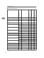
Paper Types and Sizes
This section provides the type, size, feed direction, and maximum capacity of
paper that can be loaded into each paper tray in this printer.
❒
❒
❒
❒
Note
The ”K” symbol means short-edge feed direction.
The ”L” symbol means long-edge feed direction.
The paper feed direction depends on the paper size.
This printer can automatically switch to 81/2”×11” (Letter) size paper if there
is no A4 size paper available, and vice-versa. For example, if the printer has no
A4 size paper when you want to print on A4, the printer searches for 81/2”×11”
(Letter) size paper and prints on that instead.
15
Paper and Other Media
3
Paper Feed Unit
Type305 (Tray 2/3)
Standard Tray (Tray 1)
Bypass Tray
Size (mm)
Feed direction
❖ Paper Sizes (Metric version)
13" × 18"
K
330 × 457
✩
❍
×
12" × 18"
K
305 × 457
✩
★
×
A3
K
297 × 420
✩
❍
❍
B4 JIS
K
257 × 364
✩
★ *1
★
A4
K
210 × 297
×
×
×
L
297 × 210
✩ *1
❍
❍
K
182 × 257
×
×
×
L
257 × 182
✩
★
★
K
148 × 210
×
×
×
L
210 × 148
✩
❍
×
B6 JIS
K
128 × 182
❍
×
×
A6
K
105 × 148
✩
×
×
Double Letter
K
279 × 432
✩
★
❍
Legal (LG, 81/2" × 14")
K
216 × 356
✩
★
❍
Letter (LT, 81/2" × 11")
K
216 × 279
×
×
×
L
279 × 216
✩
❍
❍
K
216 × 140
×
×
×
L
140 × 216
✩
★
×
Executive
K
184 × 276
×
×
×
(Exec., 71/4" × 101/2")
L
276 × 184
✩
★
❍
Folio (81/4" × 13")
K
210 × 330
✩
★
★
Foolscap (F4, 81/2" × 13")
K
216 × 330
✩
❍
★ *1
F/GL (8" × 13")
K
203 × 330
✩
★
★
B5 JIS
A5
(DLT, 11" × 17")
Half Letter
(HLT,
*1
16
51/
2"
×
81/
2")
:Default setting for “p” on the dial.⇒ P.26 “Specifying paper size using the operation
panel”
Paper and Other Media Supported by this Printer
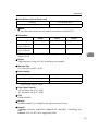
• ✩ means that the size is supported and needs to specify the paper size using
the operation panel. (Regarding the bypass tray, there is no dial on the tray.)
⇒ P.27 “Loading Paper in the Bypass Tray”
• ❍ means that the size is supported and indicated on the tray dial. Be sure to
set the paper size dial to match the actual paper size loaded in the tray.
• ★ means that the size is supported but not indicated on the paper size dial.
You should set the paper size dial to “p”, and specify the paper size using
the operation panel. The default setting is Foolscap (8.5“×13”). ⇒ P.26 “Specifying paper size using the operation panel”
• × means that the size is not supported.
The paper tray can support paper 64 – 105 g/m2 (17 – 28 lb).
The bypass tray can support paper 64 – 157 g/m2 (17 – 42 lb).
The optional paper tray can support paper 64 – 105 g/m2 (17 – 28 lb).
3
17
Paper and Other Media
3
Paper Feed Unit
Type305 (Tray 2/3)
Standard Tray (Tray 1)
Bypass Tray
Size (inch)
Feed direction
❖ Paper Sizes (Inch version)
13" × 18"
K
13" × 18"
✩
★
×
12" × 18"
K
12" × 18"
✩
❍
×
Double Letter
K
11" × 17"
✩
❍
❍
Legal (LG)
K
81/2" × 14"
✩
❍
❍
Letter (LT)
K
81/2" × 11"
×
×
×
L
11" × 81/2"
✩ *1
❍
❍
Half Letter
K
51/2" × 81/2"
×
×
×
(HLT)
L
81/2" × 51/2"
✩
★
×
Executive
K
71/4" × 101/2"
×
×
×
(Exec.)
L
101/2" × 71/4"
✩
❍
❍
A3
K
11.26” × 16.54”
✩
★
❍
B4 JIS
K
10.12” × 14.33”
✩
×
★
A4
K
8.26” × 5.83”
×
×
×
L
5.83” × 8.26”
✩
❍
❍
K
7.17” × 10.12”
×
×
×
L
10.12” × 7.17”
✩
×
★
K
5.83” × 8.26”
×
×
×
L
8.26” × 5.83”
✩
×
×
B6 JIS
K
5.04” × 7.17”
×
×
×
A6
K
4.13" × 5.83"
✩
×
×
Folio
K
81/4" × 13"
✩
★
★
Foolscap (F4)
K
81/2" × 13"
✩
★ *1
★ *1
F/GL
K
8" × 13"
✩
★
★
(DLT)
B5 JIS
A5
*1
18
: Default setting for “p” on the dial.⇒ P.26 “Specifying paper size using the operation
panel”
Paper and Other Media Supported by this Printer
• ✩ means that the size is supported and needs to specify the paper size using
the operation panel. (Regarding the bypass tray, there is no dial on the tray.)
⇒ P.27 “Loading Paper in the Bypass Tray”
• ❍ means that the size is supported and indicated on the tray dial. Be sure to
set the paper size dial to match the actual paper size loaded in the tray.
• ★ means that the size is supported but not indicated on the paper size dial.
You should set the paper size dial to “p”, and specify the paper size using
the operation panel. The default setting is Foolscap (8.5“×13”). ⇒ P.26 “Specifying paper size using the operation panel”
• × means that the size is not supported.
The paper tray can support paper 64 – 105 g/m2 (17 – 28 lb).
The bypass tray can support paper 64 – 157 g/m2 (17 – 42 lb).
The optional paper tray can support paper 64 – 105 g/m2 (17 – 28 lb).
3
19
Paper and Other Media
Precautions for Paper
Note the following precautions when handling or selecting paper to be used
with this printer.
Cautions in loading paper
Important
❒ Do not use paper that is meant for an inkjet printer. Otherwise, it may stick to
the fusing unit and cause a paper misfeed.
3
❒ When printing on an OHP transparency that has a print side, load it with the
print side down onto the bypass tray. Otherwise, it may stick to the fusing
unit and cause a misfeed.
• Use only the recommended paper types. Print quality cannot be guaranteed
if other paper types are used. ⇒ P.23 “Paper not supported by this printer”
• Do not use paper that is already printed on.
Cautions in storing paper
Paper should always be stored properly. Improperly stored paper might result
in poor print quality, paper misfeeds, or printer damage.
Follow the precautions below.
• Avoid storing paper in humid areas.
• Avoid exposing paper to direct sunlight.
• Store on a flat surface.
• Keep open reams of paper in the package in which the paper came.
Paper types and cautions
❖ Plain paper
• The standard tray can hold up to 250 sheets. *1
• The bypass tray can hold up to 50 sheets. *1
• The Paper Feed Unit Type305 (option) can hold up to 500 sheets. *1
*1
: Based on paper that is 80 g/m2 (metric version), 20 lb (inch version) in weight.
• If paper is curled or bent, correct it before loading.
Note
❒ To get the best print quality, we recommend you use paper exclusively designed for color copier.
20
Paper and Other Media Supported by this Printer
❖ Thick Paper
• If you print on paper heavier than 105 g/m2 (28 lb), use the bypass tray.
The bypass tray can hold paper up to 157 g/m 2 (42 lb) in weight. The print
quality on paper that is thicker cannot be guaranteed.
• The bypass tray can hold up to 25 sheets.
Note
❒ The number of sheets to be set may vary depending on the paper thickness and paper type.
• When printing on thick paper, you should select the thick paper mode
with the printer driver.
3
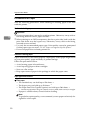
❖ Adhesive labels
• When printing on adhesive labels, use the bypass tray.
TFWY060E
• Load adhesive labels into the tray with the print side down.
• Remove any unused adhesive labels from the tray after you are finished
printing. Leaving them in the tray can cause them to curl.
• When printing on adhesive labels, you should select the plain paper mode
with the printer driver.
• The bypass tray can hold up to 40 adhesive labels.
Note
❒ The number of sheets to be set may vary depending on the paper thickness and paper type.
21
Paper and Other Media
❖ OHP transparencies
• When printing on OHP transparency, use the bypass tray.
3
TFWY060E
• Load OHP transparencies into the tray with the print side down. Otherwise, it may stick to the fusing unit and cause a misfeed.
• Remove any unused OHP transparencies from the tray after you are finished printing. Leaving them in the tray can cause them to curl.
• When printing on OHP transparencies, you should select the OHP transparency mode with the printer driver.
• The bypass tray can hold up to 50 OHP transparency sheets.
Note
❒ The number of sheets to be set may vary depending on the paper thickness and paper type.
• When the “OHP SLIP SHEET” setting is set to “NO”, be sure to remove
each OHP transparency immediately after it is printed. For more information, see the “Getting Started”.
Note
❒ This printer uses paper in tray 1 for OHP slip sheet even if the direction
and size of paper loaded in tray 1 is different from the direction and size
of the OHP transparency. Check the direction and size of paper loaded
in tray 1 before using “OHP SLIP SHEET” setting.
❒ When there is no paper in tray 1, “OHP SLIP SHEET” will not work
even if “OHP SLIP SHEET” setting is set to “YES”. Be sure to remove
each OHP transparency immediately after it is printed.
22
Paper and Other Media Supported by this Printer
Paper not supported by this printer
Avoid using the following types of paper that are not supported by this printer:
• Paper whose weight is heavier or lighter than the limitation.
• Bent, folded, or creased paper
• Curled or twisted paper
• Torn paper
• Wrinkled paper
• Damp paper
• Paper stuck together
• Paper that is dry enough to emit static electricity
• Paper that has already been printed on (with the exception of preprinted letterhead)
3
Note
❒ The ink for the format printing by a copier, or an inkjet printer and so on
might do harm to the fusing unit of this printer due to a difference in fusing
temperatures.
• Coated paper (except the recommended one)
• Special paper like thermal paper, aluminum foil, carbon paper and conductive paper
• Heavily textured paper
• Glued paper
• Label paper on which glue or base paper is exposed
• Paper with clips or stapled
• Paper with tape or ribbons attached
• Paper is meant for an inkjet printer.
• Envelopes
23
Paper and Other Media
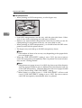
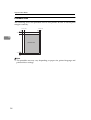
Printable Area
The following shows the printable area for this printer. Be sure to set the print
margins correctly.
4.3mm(1/6")
4.3mm(1/6")
4.3mm(1/6")
3
printable area
4.3mm(1/6")
Note
❒ The printable area may vary depending on paper size, printer language and
printer driver settings.
24
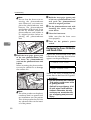
Loading Paper
Loading Paper
Loading Paper in the Paper
Tray
Use the following procedure to load
paper in the paper tray and optional
tray. See P.27 “Loading Paper in the Bypass Tray” for details on the bypass
tray.
B Slide
the paper guides to positions that match the size of paper
you want to load.
Adjust the paper guides until they
click into position.
3
Important
❒ After you load paper, you must set
the paper size dial to match the actual paper size loaded in the tray.
Otherwise, the printer might be
damaged.
Reference
See P.15 “Paper and Other Media
Supported by this Printer” for details
on supported paper types and sizes.
A Carefully pull the paper tray out
of the printer and place it on a flat
surface.
TFWY100E
Important
❒ Do not touch the friction pad
(A). Otherwise, paper misfeeds
or paper multi-feeds might occur .
C Load paper into the tray with the
print side up.
TFWY110E
TFWY090E
Important
❒ Make sure that the stack of paper is no higher than the limit
mark (TT) inside the tray.
❒ Make sure the paper fits under
the back paper guide.
25
Paper and Other Media
D Adjust
the paper size dial to
match the size of the paper in the
paper tray.
B Use {U}{T} to display “PRINTER SETUP”.
PRINTER SETUP
C Press {Enter} until “SET [*] SIZE”
appears.
SET [*] SIZE
NO
3
TFWY120E
Note
❒ For more information about the
position of the paper size dial,
see P.16 “Paper Sizes (Metric version)” or P.18 “Paper Sizes (Inch
version)”.
E Slide
the paper tray completely
into the printer.
Important
❒ Be sure to insert the paper tray
completely. Otherwise, paper
misfeeds might occur.
Use the following procedure to specify the paper size from the printer's
operation panel after loading paper
with mark “p” in the table mentioned above into tray 1, tray 2 and
tray 3.
A Press {Menu}.
TRAY1 [*] SIZE
8.5x13
*
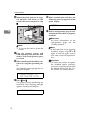
E Use {U} {T} to select the paper
size you have specified for the paper tray, and then press {Enter}.
F Press {Menu}.
The setting becomes effective.
G Press {Menu}.
The normal display screen appears.
READY
On Line
Menu
Error
Cancel
Enter
Data In
TFWS020E
26
then press {Enter} to display
“TRAY1 [*] SIZE”.
The currently selected paper size
in paper tray appears on the panel
display.
TRAY1 [*] SIZE
8x13
Specifying paper size using the
operation panel
Power
D Use {U}{T} to select “YES”, and
Loading Paper
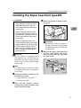
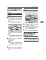
Loading Paper in the Bypass
Tray
Note
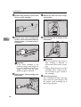
❒ Slide out the bypass tray extender.
Note
❒ Do not open the front cover when
loading paper into the bypass tray.
Reference
⇒ P.15 “Paper Types and Sizes”
⇒ P.20 “Precautions for Paper”
3
TFWY150E
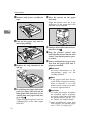
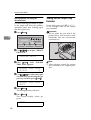
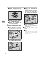
Loading paper
C Load paper until it stops with the
A Open the bypass tray.
print side down.
TFWY160E
TFWY130E
B Slide the side guides.
Important
❒ Make sure the paper fits under
the side guides.
❒ The side guides should be set to
the correct paper size to avoid
paper feed problems.
❒ Do not load paper when printing.
TFWY140E
27
Paper and Other Media
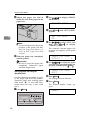
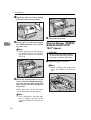
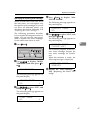
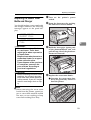
Specifying paper size using the
operation panel
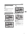
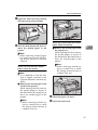
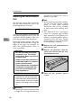
Sliding out the Output Tray
Extender
Use the following procedure to specify the paper size from the printer's
operation panel after loading paper
into the bypass tray.
If you load paper of A4L or 81/2" ×
11"L or larger, slide out the output
tray extender.
A Press {Menu}.
3
On Line
Menu
Power
Error
Cancel
Enter
Important
❒ Do not place the rear end of the
printer near a wall or touch it with
barehands. This area can become
extremely hot.
Data In
TFWS020E
B Use {U}{T} to display “PRINTER SETUP”.
PRINTER SETUP
TFWX440E
C Press
{Enter} until “BYPASS
TRAY SIZE” appears.
BYPASS TRAY SIZE
8.5x11
*
D Use {U} {T} to select the paper
size you have specified for the paper tray, and then press {Enter}.
BYPASS TRAY SIZE
8x13
E Press {Menu}.
The setting becomes effective.
F Press {Menu}.
The normal display screen appears.
READY
28
Note
❒ After printing, return the output
tray extender to its original position.
4. Troubleshooting
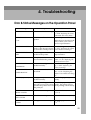
Error & Status Messages on the Operation Panel
Message
Description
Comments
ADD FUSER OIL
The fuser oil bottle is empty. Replace the fuser oil bottle.
⇒ P.50 “Replacing the Fuser
Oil Bottle and Ozone Filter”
CALL SERVICE
There is a malfunction in the Turn the printer off and on.
printer.
If this doesn't clear the problem, contact your sales or
service representative.
SC:nn
CHECK CHARGER
The charger is not set corSet the charger correctly.
rectly or the charger cleaner ⇒ P.53 “Replacing the Waste
is not in the correct position. Toner Bottle and Charger”
CHECK FUSING
The fusing unit is not installed in the printer.
Contact your sales or service
representative.
CHECK PCU
The photoconductor unit is
not installed in the printer.
Install the photoconductor
unit. ⇒ P.48 “Replacing the
Photoconductor Unit”
CHECK TONER
The toner cartridge is not in- Install the cartridge correctstalled correctly.
ly. ⇒ P.45 “Replacing the
Toner Cartridge”
UNIT
CARTRIDGE
CHECK WASTE
TONER BOTTLE
CHECK (tray name)
The waste toner bottle is not Install the waste toner botinstalled.
tle. ⇒ P.53 “Replacing the
Waste Toner Bottle and Charger”
The paper tray is not installed correctly.
Install the paper tray correctly.
The tray on the paper feed- Install the paper tray coring path was not set correct- rectly. The printer will rely when the printer received start printing automatically.
the print job.
CLOSE
The front cover is open.
Close the front cover.
(⇒ P.1)
The left cover is open.
Close the left cover. (⇒ P.1)
FRONT COVER
CLOSE
LEFT COVER
CLOSE PAPER EXIT
COVER
The paper exit cover is open. Close the paper exit cover.
(⇒ P.3)
29
Troubleshooting
Message
ERROR
POWER OFF AND ON
Description
There is a malfunction in the Turn the printer off and on.
printer.
If this doesn't clear the problem, contact your sales or
service representative.
FUSER OIL LOW
Fuser oil is low. You can
Replace the fuser oil bottle.
print about 200 or /more
⇒ P.50 “Replacing the Fuser
pages after this message ap- Oil Bottle and Ozone Filter”
pears.
LOAD PAPER
There is no paper in the indi- Load paper into the indicatcated tray.
ed tray.
IN (tray name)
LOAD BYPASS
4
There is no indicated media
(media type) (paper size) type and paper size in the
bypass tray.
Load the indicated media or
paper into the bypass tray.
LOAD (tray name)
There is no indicated paper
size in the paper tray.
Load the indicated paper
into the paper tray.
There is a paper misfeed in
the printer.
Remove the misfed paper.
⇒ P.38 “Removing Misfed Paper”
There is a difference between the position of the paper guides in the bypass
tray and the specified paper
size set with the operation
panel.
After confirming that the
paper guides are set to the
correct positions, open and
close the front cover. ⇒ P.27
“Loading Paper in the Bypass
Tray”
There is a difference between the paper size in the
paper tray and the specified
paper size set with the operation panel or the paper size
dial.
After confirming that the
size and feed derection of
paper in the paper tray is set
correctly, open and close the
front cover. ⇒ P.25 “Loading
Paper in the Paper Tray”
There is a paper misfeed in
the printer.
Remove the misfed paper.
⇒ P.38 “Removing Misfed Paper”
There is a paper misfeed in
the printer.
Remove the misfed paper.
⇒ P.38 “Removing Misfed Paper”
The fusing unit is nearly at
the end of its service life.
Contact your sales or service
representative.
(paper size)
OPEN FRONT COVER
REMOVE MISFEED
PAPER SIZE ERROR
CHECK GUIDES
↓↑
OPEN AND CLOSE
COVER TO CLEAR
PAPER SIZE ERROR
(paper size)
↓↑
OPEN AND CLOSE
COVER TO CLEAR
REMOVE MISFEED
FROM OUTPUT TRAY
REMOVE MISFEED
FROM INPUT TRAY
REPLACE
FUSING UNIT
30
Comments
Error & Status Messages on the Operation Panel
Message
Description
Comments
REPLACE PCU
The photoconductor unit is
nearly at the end of its life.
If printed side gets dirty, replace the photoconductor
unit. ⇒ P.48 “Replacing the
Photoconductor Unit”
TONER LOW
Indicated toner is low or
runs out.
Replace the indicated toner
cartridge. ⇒ P.45 “Replacing
the Toner Cartridge”
The printer is preparing for
printing.
Wait until the printer is
warmed up.
The printer adjusts itself
regularly to maintain print
quality. (This message
might appear while printing.)
It is not an error message.
The waste toner bottle is
nearly full.
Replace the waste toner bottle. ⇒ P.53 “Replacing the
Waste Toner Bottle and Charger”
The waste toner bottle is
full.
Replace the waste toner bottle. ⇒ P.53 “Replacing the
Waste Toner Bottle and Charger”
xxx
WARMING UP
WASTE TONER
ALMOST FULL
WASTE TONER
FULL
The printer is working properly. Just wait a while.
4
Note
❒ If you cannot solve the problem by taking above actions, turn the printer
power off and then back on again. If this doesn't clear the error message, write
down the error number and the message, and contact your sales or service
representative.
31
Troubleshooting
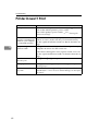
Printer Doesn't Print
Possible Cause
Solutions
Is the power on?
Make sure that the power cord is securely plugged into the
wall socket and the printer's power socket.
Turn on the printer's power switch. ⇒ P.6 “Turning the
Printer On and Off”
4
Is the interface cable
properly connecting the
printer to your computer connected securely?
Connect the interface cable properly. If there are any connectors or screws, make sure they are fastened securely.
Are you using a correct
interface cable?
The type of interface cable you should use depends on your
computer. Be sure to use the correct one.
See the "Quick Installation Guide" for details about the settings.
If the cable is damaged or worn, replace it with a new one.
See the “Quick Installation Guide” for details about the settings.
Does the On Line indicator stay on?
Press {On Line} to light it up.
Is the paper set?
Load paper into the paper tray or on the bypass tray. ⇒ P.25
“Loading Paper”
Does the Error indicator Check the error message on the panel display and do the restay red?
quired action. ⇒ P.29 “Error & Status Messages on the Operation Panel”
32
Printer Doesn't Print
Possible Cause
Solutions
Is the Data In indicator
blinking after starting
the print job?
If not, the data is not being sent to the printer. Or the printer
may be resetting the print job because there was a long delay in receiving the data from the computer.
❖ If your printer is connected to the computer using the interface cable
Confirm that the parallel port setting is set to on.
For more information on the printer port settings, see the
“Getting Started”.
❖ If the printer is using the I/O timeout setting
Increase the value of the I/O timeout setting.
For more information on the the I/O timeout setting, see
the “Getting Started”.
4
❖ Network Connection
Contact your network administrator.
If the Data In indicator is blinking.
Take the following steps to correct the situation.
• Wait until the printer finishes receiving data from the
computer.
• Cancel the job if the data sent from the computer is too
large or complex.
Can you print a test
page (configuration
page)?
If you cannot print a test page, it probably indicates a printer malfunction. You should contact your sales or service
representative.
If you can print a test page but cannot get the printer to print
when you issue a print command from your computer, it
probably means there is a problem with your computer.
Also keep in mind that large, complex data might take long
time for the printer process. For more information, see the
“Getting Started”.
If you cannot solve the problem by taking the above actions, contact your sales
or service representative.
33
Troubleshooting
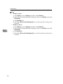
Note
• Windows 95/98
A
Click [Start], point to [Settings], and then click [Printers].
B Select the icon of the printer by clicking it. Next, on the [File] menu, click
[Properties].
C Click [Details] tab.
D Check the [Print to the following port] box to make sure the correct port is
selected.
• Windows NT4.0
A Click [Start], point to [Settings], and then click [Printers].
B Select the icon of the printer by clicking it. Next, on the [File] menu, click
[Properties].
C Click [Port] tab.
D Check the [Print to the following port] box to make sure the correct port is
selected.
4
34
Other Printing Problems
Other Printing Problems
Status
Image is printed on the reverse side of the paper.
Possible Causes, Descriptions, and Solutions
The paper in the paper tray is upside down.
• Standard Tray (Tray 1)
Load paper with the print side up.
• Bypass Tray
Load paper with the print side down.
• Optional Paper Feed Unit (Tray 2, Tray 3)
Load paper with the print side up.
Paper misfeeds occur frequently.
Check the paper size settings. The size specified with
the paper size dial might be different from the actual
paper size. Make the correct dial setting. ⇒ P.25 “Loading Paper in the Paper Tray”
4
Check if the paper tray is set correctly. If not, set it correctly. ⇒ P.25 “Loading Paper in the Paper Tray”
Paper is not loaded correctly in the paper tray. Remove
the paper from the tray and reload it correctly. ⇒ P.25
“Loading Paper in the Paper Tray”
Check the paper type settings. The type of paper set
with the printer driver might be different from the actual paper or media type. Make the correct paper or
media type setting.
You might use paper not supported by this printer. Use
the appropriate type of paper. ⇒ P.20 “Precautions for
Paper”
Multiple pages are fed
through the printer at once.
Clean the friction pad, if it is dirty. ⇒ P.42 “Cleaning the
Friction Pad”
Operation panel error message stays on after removing
the misfed paper.
After removing misfed paper, open the front cover of
your printer and then close it. ⇒ P.38 “Removing Misfed
Paper”
It takes too much time to
print the first page.
The data is so large or complex that it takes time to process it. If the Data In indicator is blinking, the data processing is being done. Just wait until it resumes.
The Energy Save mode might be enabled. In the Energy Save mode, it takes time for the machine to warm
up.
35
Troubleshooting
Status
It takes too much time to
print.
Possible Causes, Descriptions, and Solutions
Photographs and other data intensive pages take a
long time for the printer to process, so simply wait
when printing such data.
The printer takes more time to print documents that
contain a large volume of data. A blinking Data In indicator means that data is reaching the printer, so just
wait for the data to be processed and printed.
If “WARMING UP” appears on the panel display, the
printer is now warming up. Wait for a while.
It takes too much time to per- The color mode setting of the printer driver is set to colform black and white print- or mode. Change the setting to grayscale mode. For
ing.
more information, see the "User's Guide".
4
Paper isn't fed from the desired paper tray.
The printer driver setting is not correct. Change the setting. For more information, see the "User's Guide".
Desired paper size isn't used
for the output.
The printer driver setting is not correct. Change the setting. For more information, see the "User's Guide".
Check the paper size settings. The size specified with
the paper size dial might be different from the actual
paper size. Make the correct dial setting. ⇒ P.25 “Loading Paper in the Paper Tray”
Specified paper is not loaded correctly in the paper
tray. Remove the paper from the tray and reload the
specified paper correctly. ⇒ P.25 “Loading Paper in the
Paper Tray”
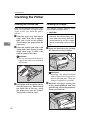
Printed side gets dirty.
The charger and dust-proofing glass are dirty. Clean
the charger and dust-proofing glass. ⇒ P.42 “Cleaning
the Charger” and P.43 “Cleaning the Dust-proofing glass”
Check the image density setting. For more information,
see the "Getting Started”.
If the message "REPLACE PCU” appears on the panel
display, replace the photoconductor unit. ⇒ P.48 “Replacing the Photoconductor Unit”
Image density is too light.
Recalibrate the printer using the operation panel. For
more information, see the “Getting Started”.
If the message “TONER LOW XXX” is on the panel display, replace the toner cartridge for the indicated color.
⇒ P.45 “Replacing the Toner Cartridge”
You might be using paper not supported by this printer. Use the appropriate type of paper. ⇒ P.20 “Precautions for Paper”
36
Other Printing Problems
Status
Possible Causes, Descriptions, and Solutions
Black or white lines appear
on the print side.
The charger and dust-proofing glass are dirty. Clean
the charger and dust-proofing glass. ⇒ P.42 “Cleaning
the Charger” and P.43 “Cleaning the Dust-proofing glass”
Smeared toner appears on
the printed side.
The charger is dirty. Clean the charger. ⇒ P.42 “Cleaning the Charger”
Part of the printout is blurred If the message “TONER LOW XXX” is on the panel disor light.
play, replace the toner cartridge for the indicated color.
⇒ P.45 “Replacing the Toner Cartridge”
Toner is not fused well when The printer is not in thick paper or OHP transparency
mode. Select thick paper or OHP transparency mode
printing on thick paper or
using the printer driver. For more information, see the
OHP transparencies.
"User's Guide”.
The color of the printout
doesn't match the color on
the computer's display.
4
The toner based color system used by the printer is different from the light based color system of the computer screen. For more information, see the "User's
Guide”.
Recalibrate the printer using the operation panel. For
more information, see the "Getting Started”.
Change the printer driver settings. For more information, see the "User's Guide”.
Color documents are printed The printer driver is not set up for color printing.
in black and white.
Change the setting to color printing. For more information, see the "User's Guide".
Thin lines are blurred or
light.
Change the halftone settings of the printer driver. For
more information, see the "User's Guide”.
When printing on OHP
There is no paper in tray 1. Load the same size and ditransparencies, a sheet of pa- rection paper as the OHP transparency into tray 1.
per is not placed between
The "OHP SLIP SHEET” setting is set to "NO”. Change
printed OHP transparencies.
the setting with operation panel. For more information,
see the "Getting Started”.
Note
❒ If you cannot solve the problem by taking above actions, contact your sales or
service representative.
37
Troubleshooting
Removing Misfed Paper
When a paper misfeed occurs, an error message appears on the panel display. The procedure you should
follow to remove the misfed paper
depends on its location which is indicated on the panel display.
R CAUTION:
• When removing misfed pa-
per, do not touch the fusing
section because it could be
very hot.
4
• When accessing the inside of
the machine, do not touch any
sections other than those
specified in this manual. If you
do, it might result in receiving
a burn or injury.
Important
❒ If your printer is equipped with
the optional tray, do not pull out
more than one tray with paper at a
time. If you do, the printer might
tilt forward.
❒ Check the following points if paper continues to misfeed.
• Make sure paper is properly
loaded in the paper tray.
• Make sure the number of sheets
do not exceed the maximum capacity of the tray.
• Make sure you are using only
the appropriate type of paper.
• Make sure misfed paper is still
not inside the printer when you
resume printing.
• Check the paper type settings.
The type of paper set with the
printer driver might be different
from the actual paper or media
type. Make the correct paper or
media type setting.
38
❒ Make sure the size of the paper
loaded in tray 1 is same as the size
of the OHP transparency.
❒ If misfeeds persist, contact your
sales or service representative.
❒ Do not touch the photoconductor
unit when removing misfed paper.
If you do, the photoconductor unit
might be damaged.
❒ Exposing the photoconductor unit
to light for too long can reduce its
performance. Close the cover as
quickly as possible.
❒ After removing the misfed paper,
the back sides of the next printout
might get dirty. Print a few pages
to absorb the toner.
Removing Misfed Paper
When the Message "REMOVE
MISFEED FROM INPUT TRAY"
Appears
Bypass tray
A Carefully pull the misfed paper.
Make sure that you do not leave
any misfed paper in the printer.
Standard Tray (Tray 1) or Paper Feed Unit
(Tray 2/3)
A Pull out the paper tray gently, being careful not to tear the misfed
paper, and remove the misfed paper.
Make sure that you do not leave
any misfed paper in the printer.
4
TFWY180E
B When paper is left in the bypass
tray, remove the paper.
C Close
the bypass tray, open the
front cover, and then close it to reset the misfeed condition.
D Reload paper into the bypass tray.
TFWY170E
Note
❒ If your printer has an optional
paper feed unit installed, check
all paper trays for misfeeds.
B Slide
the paper tray completely
into the printer.
Important
❒ Be sure to insert the paper tray
completely. Otherwise, misfeeds might occur, or the front
cover might touch the paper
tray.
When the Message "OPEN
FRONT COVER REMOVE
MISFEED" Appears
R CAUTION:
• When removing misfed paper,
do not touch the fusing section
because it could be very hot.
C Open
the front cover, and then
close it to reset the misfeed condition.
39
Troubleshooting
A Open the front cover by pushing
the front cover release button.
TFWX220E
TFWX080E
B If the paper is in the front side of
4
the photoconductor unit, carefully pull it out.
Note
❒ When removing misfed paper,
be careful not to touch the fusing section because it could be
very hot.
D Close the front cover.
When the Message "REMOVE
MISFEED FROM OUTPUT
TRAY" Appears
R CAUTION:
• When removing misfed paper,
do not touch the fusing section
because it could be very hot.
A Open the paper exit cover.
Note
❒ When opening the paper exit
cover, be careful as it may be
hot.
TFWX210E
C When the misfed paper is in the
main section of the photoconductor unit, turn the dial downward
then remove the misfed paper in
the printer.
Make sure that you do not leave
any misfed paper in the printer.
Note
❒ If it is difficult to turn the dial,
turn it slightly upward in the
opposite direction, and then try
again.
40
TFWX230E
Removing Misfed Paper
B Open the front cover by pushing
the front cover release button.
TFWX220E
TFWX080E
C Turn the dial downward, then remove the misfed paper in the
printer.
Note
❒ When removing misfed paper,
be careful not to touch the fusing section because it could be
very hot.
When you can see the misfed
paper inside the printer.
Note
❒ If it is difficult to turn the dial,
turn it slightly upward in the
opposite direction, and then try
again.
A Remove the misfed paper from
inside of the printer.
While turning the dial, remove
the misfed paper as shown in
the illustration. Be careful not to
leave any misfed paper in the
printer.
Note
❒ When removing misfed paper, be careful not to touch
the fusing section because it
could be very hot.
When you cannot see the misfed
paper inside the printer.
4
A Remove the misfed paper from
the output tray.
While turning the dial, remove
the misfed paper as shown in
the illustration. Be careful not to
leave any misfed paper in the
printer.
Note
❒ When removing misfed paper, be careful not to touch
the fusing section because it
could be very hot.
TEWX240E
D Close the paper exit cover.
E Close the front cover.
41
Troubleshooting
Cleaning the Printer
Cleaning the Friction Pad
Cleaning the Charger
If the friction pad becomes dirty, misfeeds or multi-feeds of paper might
occur. In this case, clean the pad as
follows:
The charger requires cleaning when
your printouts appear dirty.
A Slide the paper tray out until it
stops. After that, lift it slightly,
then pull it out of the printer.
Then remove the paper from the
paper tray.
4
B Clean the friction pad with a soft
damp cloth. After wiping it with a
damp cloth, wipe it with a dry
cloth to remove the water.
R CAUTION:
• When accessing the inside of the
machine, do not touch any sections other than those specified
in this manual. If you do, it might
result in receiving a burn or injury.
A Open the front cover by pushing
the front cover release button.
Important
❒ Do not use chemical cleaners or
organic solvents such as thinner
or benzene.
TFWX080E
TFWY230E
C Load paper with the print side up
into the paper tray. While lifting
the front side of the tray, insert
the paper tray into the printer.
Then push in until it stops.
42
Important
❒ Exposing the photoconductor
unit to light for too long can reduce its performance. Clean the
charger as quickly as possible.
B Hold the inset grips (green part)
of the photoconductor unit, and
pull the top side of the photoconductor unit forward.
TFWX250E
Cleaning the Printer
C Move
the charger cleaner (light
blue part) left and right 2 or 3
times, and return it to the left
side. Set the arrow of the charger
cleaner to the arrow of the photoconductor unit.
A Open the front cover by pushing
the front cover release button.
TFWX080E
TFWX260E
Important
❒ If the charger cleaner is not on
the left side, an error message or
print problem might occur.
D Hold the inset grips (green part)
of the photoconductor unit, and
push the photoconductor unit to
its original position.
Important
❒ Exposing the photoconductor
unit to light for too long can reduce its performance. Clean the
dust-proofing glass as quickly
as possible.
4
B Hold the inset grips (green part)
of the photoconductor unit, and
pull the top side of the photoconductor unit forward.
E Close the front cover.
Cleaning the Dust-proofing
glass
The dust-proofing glass may require
cleaning if black or white lines appear
on the print side of the document.
R CAUTION:
• When accessing the inside of the
TFWX250E
C Remove the cleaning brush from
back of the front cover.
machine, do not touch any sections other than those specified
in this manual. If you do, it might
result in receiving a burn or injury.
TFWX270E
43
Troubleshooting
D Insert the cleaning brush into the
back of the guide (light blue) until it stops, and then move it left
and right 4 or 5 times.
TFWX280E
4
E Return the cleaning brush to its
original position.
F Hold the inset grips (green part)
of the photoconductor unit, and
push the photoconductor unit to
its original position.
G Close the front cover.
44
Replacing Consumables
Replacing Consumables
Replacing the Toner Cartridge
A Open the left cover.
You should replace toner cartridges
whenever the message “TONER
LOW XXX” appears on the panel display.
TONER LOW
xxx
R WARNING:
• Do not incinerate spilled toner
or used toner. Toner dust
might ignite when exposed to
an open flame.
4
TFWX140E
B Slide the lock lever up.
• Disposal can take place at our
authorized dealer or at appropriate collection sites.
• If you dispose of the used toner containers yourself, dispose of them according to
your local regulations.
Note
❒ Before removing a toner cartridge
from the printer, spread paper or
some other material around the
area you are working to keep toner
from making floor dirty.
❒ When several toner colors run out
at the same time, a message appears on the operation panel. Replace them in the following order:
A Black
B Yellow
C Cyan
D Magenta
❒ When there is no all color toner
cartridges that you want to replace, you can specify the replacing toner cartridges. ⇒ P.47
“Specifying the replacing toner cartridge”
TFWX150E
C Carefully pull out the toner car-
tridge.
A Hold the grip of the toner cartridge, and slide it out until
you can see the green tape.
B With your hand under the
green tape, remove the toner
cartridge carefully as shown in
the illustration.
TFWX480E
45
Troubleshooting
D Remove the protective sheet from
the new toner cartridge.
G Return the lock lever to its original position.
TFWX490E
E Hold the new
toner cartridge and
shake it with a horizontal motion,
about 10 times, as shown in the illustration.
4
TFWX170E
H Pull the tape out as shown in the
illustration.
TFWX510E
TFWX500E
Important
❒ If the toner cartridge is not
shaken enough, toner might not
be evenly distributed in the cartridge. In this case, the print
quality might be reduced.
F Slide the new toner cartridge into
the printer.
Important
❒ Be sure to pull the tape horizontally. Pulling it upward or
downward causes toner scattering.
❒ After pulling the tape out of the
cartridge, toner scatters easily.
Do not shake or give a shock to
the cartridge.
I Close the left cover.
The “TONER LOW XXX” message
clears from the panel display and
the printer starts warming up. It
takes a few minutes.
TFWX160E
46
Replacing Consumables
Specifying the replacing toner cartridge
When several toner colors run out at
the same time, you can replace only
the specific toner cartridges. If you do
not have all indicated toners, you
should do this before following P.45
“Replacing the Toner Cartridge”.
The following procedure describes
how to replace the magenta toner cartridge. You can use the same procedure to replace the toner cartridges
for the other toner colors as well.
A Press {Menu}.
{Enter} to display "MAGENTA TONER”.
The following message appears on
the panel display.
MAGENTA TONER
NO
*
E Use {U}{T} to select “YES”, and
then press {Enter}.
The following message appears on
the panel display.
4
MAGENTA TONER
PLEASE WAIT
On Line
Menu
Power
D Press
Cancel
Error
Enter
Data In
TFWS020E
B Use {U}{T}
to display "MAINTENANCE", and then press {Enter}.
REPLACE TONER
MAGENTA
F Replace
MAINTENANCE
The following message appears on
the panel display.
SELECT TONER
NO
The machine prepares itself for a
new toner cartridge. Prepare the
new toner cartridge for installation.
When the machine is ready, the
following message is displayed.
the toner cartridge. ⇒
P.45 “Replacing the Toner Cartridge”
*
C Use {U}{T} to select “YES”, and
then press {Enter}.
The following message appears on
the panel display.
CYAN TONER
NO
*
47
Troubleshooting
Replacing the Photoconductor
Unit
The message shown below indicates
that the photoconductor unit is approaching the end of its life.
REPLACE PCU
You can still continue to use the current photoconductor unit if you are
satisfied with the quality of the output being produced by the printer.
When the printed image starts looking soiled (horizontal lines along the
edges of the page, for example), replace the photoconductor unit as
soon as possible.
4
R WARNING:
• Do not incinerate the photo-
conductor unit. Toner dust
might ignite when exposed to
an open flame.
performance. Replace the unit as
quickly as possible.
Note
❒ Before removing the photoconductor unit from the printer, spread
paper or some other material
around the area you are working
to keep toner from making floor
dirty.
❒ The “REPLACE PCU” message is
based on a printed page counter
kept internally by the printer. It is
meant as a general guide to photoconductor unit life only. Actual
photoconductor unit life depends
on the printing conditions.
A Remove the new photoconductor
unit from the box.
B Remove
the protective sheet by
pulling the red tab from the new
photoconductor unit.
• Disposal can take place at our
authorized dealer or at appropriate collection sites.
• If you dispose the used photoconductor unit yourself, dispose of it according to your
local regulations.
R CAUTION:
• When accessing the inside of the
machine, do not touch any sections other than those specified
in this manual. If you do, it might
result in receiving a burn or injury.
Important
❒ Exposing the photoconductor unit
to light for too long can reduce its
48
TFWX471E
C Turn
off the printer's power
switch.
Replacing Consumables
D Open the front cover by pushing
the front cover release button.
G Hold the inset grips (green part)
of the photoconductor unit, remove the photoconductor unit
from the printer, and place it carefully inside the new photoconductor unit's box.
TFWX080E
E Loosen the screws that hold the
photoconductor unit in the printer with the screw driver in the
new photoconductor unit's box.
The screws cannot be completely
removed from the photoconductor
unit.
4
TYWX290E
Important
❒ To prevent accidental spilling of
toner, do not shake, rotate, drop
or hold the toner cartridge upside down.
TFWX400E
TFWX520E
F Hold the inset grips (green part)
of the photoconductor unit, and
pull the top side of the photoconductor unit forward.
TFWX250E
49
Troubleshooting
Note
❒ Do not close the front cover removing the photoconductor
unit. Otherwise, you cannot replace the photoconductor unit
because the photoconductor
unit holder will be closed. If you
do this by mistake, return the
photoconductor unit holder to
its original position before replacing the photoconductor
unit.
I Hold the inset grips (green part)
of the new photoconductor unit,
and push the photoconductor
unit to its original position.
J Fix the photoconductor unit with
fastening the screws using the
screw driver.
K Close the front cover.
Make sure that the front cover
close properly.
L Turn
on the printer’s power
switch.
4
TFWX300E
H Hold the inset grips (green part)
of the new photoconductor unit,
and insert the photoconductor
unit into the photoconductor unit
holder.
When inserting the photoconductor unit, be careful not to damage
the surface of it.
Replacing the Fuser Oil Bottle
and Ozone Filter
Replace the oil bottle and ozone filter
whenever the message shown below
appears on the panel display.
FUSER OIL LOW
ADD FUSER OIL
There is the fuser oil bottle and the
ozone filter in the Fuser Oil Type305.
R WARNING:
• Do not incinerate the oil bottle.
This action could cause a fire
or getting burned.
TFWX305E
Note
❒ The white powder on the photoconductor unit is to protect it after installation into the printer.
This white powder doesn't have
any adverse effect on the interior of the printer.
50
• Spilt oil is very slippery. If oil
is spilt, wipe it with alkaline
cleaner. Otherwise, the oily
surfaces can create the danger of slipping and personal
injury.
Replacing Consumables
R CAUTION:
• When accessing the inside of the
B Open the fuser oil bottle cover
of the printer.
machine, do not touch any sections other than those specified
in this manual. If you do, it might
result in receiving a burn or injury.
Important
❒ There are three ozone filters in this
printer. Two of them are set inside
in the front, one of them is set in
the rear. Be careful when replacing
the ozone filters as the front side
filter is a different shape from the
rear side filter.
❒ Disposal can take place at our authorized dealer or at appropriate
collection sites.
❒ Dispose of used ozone filters as
general burnable refuse.
TFWX090E
C Remove the used oil bottle
from the printer carefully.
D Insert the new oil bottle into
the oil bottle case.
4
A Turn
off the printer's power
switch.
B Replace the oil bottle.
TFWX100E
A Remove the green cap from the
new oil bottle.
Important
❒ Hold the clear cap while
turning the green cap. Do not
remove the clear cap.
E Close the fuser oil bottle cover.
Important
❒ The fuser oil bottle cover
should be kept closed.
C Replace
the ozone filter on the
back side of the printer.
A Remove the ventilator hole
cover.
TFWX031E
TFWX960E
51
Troubleshooting
B Remove the ozone filter from
inside the ventilator hole cover.
C Insert a new ozone filter into
the printer.
Slide the filter into the stopper.
Two small thin plastic tabs of
the top of the filter should pop
into place.
TFWX070E
C Install a new ozone filter on
the ventilator hole cover.
D Replace the ventilator hole
cover onto the printer.
4
D Replace
the ozone filters inside
the printer. (There are two filters.)
A Open the front cover by pushing the front cover release button.
TFWX320E
D Close the front cover.
Make sure that the front cover
close properly.
E Turn
on the printer’s power
switch.
Note
❒ After replace the fuser oil bottle,
it takes a few minutes until the
message clears.
TFWX080E
B Grasping the ozone filter by its
tab, remove it from the printer.
TFWX310E
52
Replacing Consumables
Replacing the Waste Toner
Bottle and Charger
You should replace waste toner bottle
and charger whenever the following
messages appear on the panel display.
A Turn
on the printer’s power
switch.
B Open the front cover by pushing
the front cover release button.
WASTE TONER
ALMOST FULL
WASTE TONER
FULL
R WARNING:
• Do not incinerate spilled toner
or used toner. Toner dust
might ignite when exposed to
an open flame.
4
TFWX080E
C Hold the inset grips (green part)
of the photoconductor unit, and
pull the top side of the photoconductor unit forward.
• Disposal can take place at our
authorized dealer or at appropriate collection sites.
• If you dispose of the used toner containers yourself, dispose of them according to
your local regulations.
R CAUTION:
• When accessing the inside of the
machine, do not touch any sections other than those specified
in this manual. If you do, it might
result in receiving a burn or injury.
TFWX250E
D Replace the waste toner bottle .
A Grasping the waste toner bottle by its green tabs, remove it
from the printer.
Note
❒ Before removing the waste toner
bottle from the printer, spread paper or some other material around
the area you are working to keep
toner from making floor dirty.
TFWX330E
53
Troubleshooting
B Insert a new waste toner bottle
at the rear of the photoconductor unit.
Insert a new waste toner bottle
completely. Otherwise, print
problem may occur.
TFWX460E
Note
❒ Return the charger cleaner to
the left side. Otherwise, print
problem may occur.
4
TFWX340E
E Replace the charger.
A Push the right and left lock levers of the charger.
The locks release, and the charger is lifted slightly.
F Hold the inset grips (green part)
of the new photoconductor unit,
and push the photoconductor
unit to its original position.
G Close the front cover.
Make sure that the front cover
close properly.
H Turn
on the printer’s power
switch.
TFWX450E
B Remove the charger.
C Install a new charger into the
printer.
Insert the new charger into the
printer with the arrow of the
charger cleaner's lever facing toward you. The charger locks automatically.
54
5. Appendix
Moving and Transporting the Printer
R CAUTION:
• It is recommended that at least two persons are used to lift the machine.
Otherwise, the machine might fall and cause personal injury.
• When lifting the machine, use the inset grips on both sides of the machine.
Otherwise, the machine might fall and cause personal injury.
• When you move the machine, unplug the power cord from the wall socket
to avoid a fire or an electric shock.
• When you pull out the plug from the socket, grip the plug to avoid damaging
the cord and causing a fire or an electric shock.
• When moving the printer, be sure to keep it level to avoid spilling the fuser
oil. If oil is spilt, wipe it with alkaline cleaner. Otherwise, the oily surfaces
can create the danger of slipping and personal injury.
Important
❒ Be sure to disconnect all cables from the printer before transporting it.
❒ The printer is a precision piece of machinery. Take care to avoid damage during shipment.
55
Appendix
Specifications
Mainframe
❖ Configuration:
Desktop
❖ Print Process:
Laser beam and dry toner electrical photographic system
❖ Printing Speed:
Monochrome: 17 pages per minute (A4, 81/2"×11")
Color: 5 pages per minute (A4, 81/2"×11")
❖ Resolution:
600 dpi
5
❖ Parallel Interface:
Conforms to the standard centronics
Interface
A standard 36-pin printer cable and a parallel port on the host computer
Mode
Compatible, Nibble, ECP
Connector
IEEE P1284-B
• Do not use a cable more than 2.5 meters (8.2 feet) long.
❖ Printer Language:
Adobe PostScript Level3, PCL5c/5e
❖ Paper Size:
⇒ P.15 “Paper and Other Media Supported by this Printer”
❖ Paper Weight:
⇒ P.15 “Paper and Other Media Supported by this Printer”
❖ Power Source:
⇒ Inside of the front cover of this manual
❖ Power Consumption:
56
Standby (Maximum)
150 W or less
Printing (Maximum)
1,200 W or less
Printing (Average)
750 W or less
Energy Save (Maximum)
45 W or less
Specifications
❖ Noise Emission (Sound Power Level):
Printing
Less than 64 db(A)
Stand-by
Less than 43 db(A)
Note
❒ The above measurements are made in accordance with ISO7779.
❖ Dimensions:
Width
Depth
Height
Printer only
660 mm (26")
625 mm (24.7")
475 mm (18.8")
With one optional
paper feed unit
660 mm (26")
625 mm (24.7")
601 mm (23.7")
With two optional
paper feed units
660 mm (26")
625 mm (24.7")
727 mm (28.7")
5
Measurement conditions: With paper tray, bypass tray and output tray extender closed.
❖ Weight:
Approximately 62 kg (136.7 lb) (including consumables)
❖ Warm-up Time:
Less than 450 seconds (23°C)
❖ Paper Capacity:
Standard paper tray
250 sheets *1
Bypass tray
50 sheets *1
Optional paper feed unit
500 or 1,000 sheets
*1
*1
Paper weight: 80 g/m2, 20 lb
❖ Paper Output Capacity:
A4: 250 sheets (80 g/m2, 20 lb)
A3: 100 sheets (80 g/m2, 20 lb)
❖ CPU:
R4700-133MHz
❖ Memory:
Standard 32MB, Up to 160MB (with optional memory unit)
❖ Network:
Topology: Ethernet (10BASE-T/100BASE-TX, 10BASE5), TokenRing (Option)
Protocol: TCP/IP, IPX/SPX, AppleTalk, SMB
57
Appendix
❖ Optional Equipment:
• Paper Feed Unit Type305
• Memory Unit Type505 (32MB/64MB) (DIMM)
• Printer Hard Disk Type505
5
58
Specifications
Options
Paper Feed Unit Type305
❖ Paper Size:
⇒ P.15 “Paper Types and Sizes”
❖ Paper Weight:
⇒ P.15 “Paper Types and Sizes”
Memory Unit Type505 (32MB) and Memory Unit Type505 (64MB)
❖ Model Type:
DIMM (Dual In-Line Memory Module)
5
❖ Memory Type:
PC100 SDRAM (precisely described as PC100 Rev1.0 compatible)
❖ Number of Pins:
168 pins
❖ Access Time (Frequency):
100MHz
❖ CAS Latency:
2
Printer Hard Disk Type505
❖ Type:
2.5 inch slim type (8.45mm height)
❖ Storage Capacity (Formatted):
1.62GB
❖ DIsk Rotational Speed:
4,200rpm
❖ Seek Time (Average):
13ms
❖ Host Interface:
EIDE (UDMA mode supported)
59
Appendix
Consumables
R CAUTION:
• Our products are engineered to meet the highest standards of quality and
functionality. When purchasing expendable supplies, we recommend using
only those specified by an authorized dealer.
❖ Toner Cartridge
Average printable number of pages per cartridge *1
5
COLOR TONER Type305 Cyan
15,000 pages
COLOR TONER Type305 Magenta
15,000 pages
COLOR TONER Type305 Yellow
15,000 pages
TONER Type305 Black
15,000 pages
*1
A4 5% test chart
Note
❒ The actual number of printed pages you get from a particular toner cartridge depends on the type and size of paper you are using, the contents of
your print images, and printing environment conditions. The life of a toner
cartridge also shortens as the cartridge becomes older. All this means that
a toner cartridge might require replacement sooner than the normal life described above.
❒ Toner cartridges that come with the printer are for setup purposes, and
will not provide the number of pages described above. The average number of printable pages that can be expected from the toner cartridges included in the printer are as follows:
• Black toner cartridge : about 6,000 pages
• Cyan, magenta and yellow toner cartridges : about 3,000 pages for each
60
Consumables
❖ Other Consumables
Note
❒ Actual life of consumables depends on the type and size of paper you are
using, the contents of your print images, and printing environment conditions. The life of consumables also shortens as the consumables become
older. All that means that consumables might require replacement sooner
than the life indicated.
Service Life *1
Waste Toner Bottle Type305 *4
20,000 pages *2
5,000 pages *3
Photo Conductor Unit Type305
60,000 pages *2
15,000 pages *3
Fuser Oil Type305
*1
*2
*3
*4
20,000 pages
5
A4 5% test chart
For monochrome printing
For full color printing
Waste Toner Bottle Type305 includes a charger.
61
INDEX
A
Adhesive labels, 21
B
Back Plate, 3
Bypass Tray, 2, 27
C
{Cancel} key, 5
Charger, 4, 42, 53
D
Data In indicator, 5
Dust-proofing glass, 43
E
{Enter} key, 5
Error indicator, 5
Error & Status Messages on the Operation
Panel, 29
F
Friction Pad, 42
Front Cover, 1
Front Cover Release Button, 1
Fuser Oil Bottle, 4, 50
Fuser Oil Bottle Cover, 1
O
OHP transparency, 22
On Line indicator, 5
{On Line} key, 5
Operation Panel, 1
Options, 7
Output Tray, 1
Output Tray Extender, 1, 28
Ozone Filter, 3, 4, 50
P
Panel Display, 5
Paper, 15, 25
Paper Exit Cover, 3
Paper Feed Unit Type305, 8, 13
Paper Tray, 2, 25
Parallel Interface Connector, 3
Photoconductor Unit, 4, 48
Plain paper, 20
Power Connector, 3
Power indicator, 5
Power Switch, 1
Printable Area, 24
Printer Hard Disk Type505, 8, 11
T
Thick Paper, 21
Toner Cartridge, 4, 45
V
I
Inset Grips, 1
L
Left Cover, 1
Ventilator, 3
W
Waste Toner Bottle, 4, 53
M
Memory Unit Type505, 8, 9
{Menu} key, 5
Misfed Paper, 38
N
Network Interface Connector for 10BASE5, 3
Network Interface Connector for
10BASE-T/100BASE-TX, 3
62
UE
USA G024