1
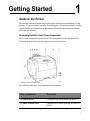
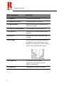
RICOH COLOR LASER
PRINTER AP505
OPERATING INSTRUCTIONS
Read this manual carefully before you use this product and keep it handy for
future reference. For safety, please follow the instructions in this manual.
Ricoh Corporation
© 1999 Ricoh Co., Ltd.
This equipment has been tested and found to comply with the limits from a Class B digital device,
pursuant to Part 15 of the FCC Rules. These limits are designed to provide reasonable protection against
harmful interference in a residential installation. This equipment generates radio frequency energy and if
not installed and used in accordance with the instructions, may cause harmful interference to radio
communications.
However, there is no guarantee that interference will not occur in a particular installation. If this
equipment does cause harmful interference to radio or television reception, which can be determined by
turning the equipment off and on, the user is encouraged to try to correct the interference by one or more
of the following measures:
•
•
•
•
Reorient or relocate the receiving antenna.
Increase the separation between the equipment and receiver.
Connect the equipment into a outlet that is different from the receiver’s outlet.
Consult the dealer or an experienced radio/TV technician for help.
Changes or modifications not expressly approved by the party responsible for compliance could void the
user’s authority to operate the equipment.
Product Name: Printer
Model Number: G024-17
Responsible party: Ricoh Corporation
Address: 5 Dedrick Place, West Caldwell, NJ 07006
Telephone number: 973-882-2000
This device complies with part 15 of FCC Rules.
Operation is subject to the following two conditions:
•
•
This device may not cause harmful interference.
This device must accept any interference received, including interference that may cause undesired
operation.
Properly shielded cables must be used for connections to the host computer and peripherals in order to
meet FCC emission limits. Network interface cable with a ferrite core must be used for RF interference
suppression.
Parts of this manual are subject to change without prior notice. The company will not be liable for direct,
indirect, special, incidental, or consequential damages as a result of handling or operating the machine.
Windows ®, and Windows NT ® are registered trademarks of Microsoft Corporation in the United States
and other countries. PostScript ® is a registered trademark of Adobe Systems, Incorporated. AppleTalk
®, is a registered trademark of Apple Computer, Incorporated.
Other product names used herein are for identification purposes only and are trademarks of their
respective companies. We disclaim any and all rights in those marks. Ricoh assumes no responsibility
with regard to the performance or use of these products.
Some illustrations might be slightly different from your machine. Certain options might not be available
in some countries. For details, please contact your local dealer.
CONTENTS
Chapter 1
Getting Started
Guide to the Printer . . . . . . . . . . . . . . . . . . . . . . . . . . . . . 1
Reviewing Exterior-Front View Components . . . . . . . 1
Reviewing the Exterior-Rear View Components . . . . . 3
Reviewing the Interior Components . . . . . . . . . . . . . . 5
Reviewing the Operation Panel. . . . . . . . . . . . . . . . . . 7
Turning the Printer On and Off . . . . . . . . . . . . . . . . . . . . . 9
Turning Your Printer On . . . . . . . . . . . . . . . . . . . . . . . 9
Turning Your Printer Off . . . . . . . . . . . . . . . . . . . . . . 10
Chapter 2
Installing Options
Reviewing the Available Options. . . . . . . . . . . . . . . . . . .
Installing the Memory Unit Type505 (DIMM). . . . . . .
Installing the Printer Hard Disk Type505. . . . . . . . . .
Installing the Paper Feed Unit Type305 . . . . . . . . . .
Chapter 3
Loading Paper
Reviewing the Paper Loading Options . . . . . . . . . . . . . .
Loading Paper in the Paper Tray . . . . . . . . . . . . . . .
Specifying Paper Size Using the Operation Panel . .
Loading Paper in the Bypass Tray . . . . . . . . . . . . . .
Specifying Paper Size Using the Operation Panel . .
Chapter 4
11
12
14
16
21
21
23
24
26
Troubleshooting
Troubleshooting and Maintaining the Printer . . . . . . . . .
Understanding Why the Printer Doesn’t Print . . . . . .
Removing Misfed Paper from the Input Tray . . . . . .
Removing Misfed Paper from the Bypass Tray. . . . .
Removing Misfed Paper from the Front Cover . . . . .
Removing Misfed Paper from the Output Tray . . . . .
Replacing the Toner Cartridge . . . . . . . . . . . . . . . . .
Replacing a Specific Toner Cartridge . . . . . . . . . . . .
27
27
29
30
30
32
34
37
iii
iv
Getting Started
1
Guide to the Printer
This manual contains detailed instructions on the operation and maintenance of this
machine. To get maximum versatility from this printer, all operators should carefully
read and follow the instructions in this manual. Please keep this manual in a handy
place near the machine.
Reviewing Exterior-Front View Components
This section describes the external-front view components of the laser printer The
following diagram illustrates the printer and its external features:
Exterior-front view of laser printer
The following table lists each component and its purpose:
This component
Does this
(1) Power switch
Use this switch to turn printer on and off.
(2) Fuser oil bottle cover
Open this cover when replacing the fuser oil
bottle.
1
Operating Instructions
2
This component
Does this
(3) Output tray
Used to stack printed pages.
(4) Output tray extender
Used for printing on long paper.
(5) Operation panel
Shows the printer status and contains keys
for printer operation.
(6) Front cover release button
Use this button to open the front cover.
(7) Front cover
Open this cover when accessing the inside of
the printer.
(8) Left cover
Open this cover when replacing the toner
cartridge.
(9) Inset grips
Hold the printer at the location indicated in
the illustration when transporting it. Note
that there are four grips, two on the left side
and two on the right side of the printer.
(10) Bypass tray
Used to print on to thick paper,
transparencies and adhesive labels in
addition to plain paper.
(11) Paper tray
Load paper into this tray for printing.
Reviewing the Exterior-Rear View Components
Reviewing the Exterior-Rear View Components
This section describes the components of the exterior-rear view of the laser
printer.The following diagram illustrates the position of these components.
Exterior-rear view of laser printer
The following table lists each component and its purpose:
This component
Does this
(1) Paper exit cover
Open this cover when removing misfed paper
at the fusing unit.
(2) Ozone filter
This filter reduces the amount of ozone that
is discharged into the air.
3
Operating Instructions
This component
Does this
(3) Ventilator
This hole allows the air to circulate,
preventing components inside the printer
from overheating.
Caution:
Do not leave the ventilator obstructed or
blocked. Doing so creates the danger of
malfunction due to overheating.
(4) Back plate
Remove to install some options.
(5) Parallel interface connector
Plug the interface cable that connects the
printer to your computer into this connector.
Note: Rating voltage of the parallel
interface connector for the computer is a
maximum of 5V DC (Direct Current).
(6) Network interface
connector for 10BASE-T/
100BASE-TX
Plug the network interface cable for
10BASE-T/100BASE-TX, that connects the
printer to the network, into this connector.
Note: Rating voltage of the network
interface connector for 10BASE-T/
100BASE-TX is a maximum of 5V DC
(Direct Current)
(7) Network interface
connector for 10BASE5
Plug the network interface cable for
10BASE5, that connects the printer to the
network, into this connector.
Note: Rating voltage of the network
interface connector for 10BASE5 is a
maximum of 5V DC (Direct Current).
4
Reviewing the Interior Components
This component
Does this
(8) Ventilator
This hole allows air to circulate, preventing
components inside the printer form
overheating.
Caution:
Do not leave the ventilator obstructed or
blocked. Doing so creates a danger of
malfunction due to overheating.
(9) Power connector
Connect the power cord to this connector.
Reviewing the Interior Components
This section describes the interior components of the laser printer. The following
diagram illustrates the interior view of the printer:
Interior view of the laser printer
The following table list each component and its purpose:
5
Operating Instructions
This component
Does this
(1) Toner cartridge
Houses the toner for the printer.
(2) Fuser oil bottle
Holds oil for fusing the toner to the paper.
(3) Ozone filters
Reduces the amount of ozone that is
discharged into the air.
(4) Charger wire
Gives the toner and electrostatic charge so
that it will stick to the paper.
(5) Waste toner bottle
A receptacle for waste toner generated during
the printing process.
(6) Photoconductor unit
Used to compose the image being printed.
Note: Screws are used to hold the
photoconductor unit in place. Be sure to
remove the screws before attempting to
remove the unit.
Note: The condition of the photoconductor
unit belt directly affects output appearance
and quality. Always be careful to prevent the
green film in this unit from becoming dirty or
damaged. Do not touch the black belt. Do not
rotate the gear on the right side of the printer.
Otherwise, the inside belt will be damaged.
6
Reviewing the Operation Panel
Reviewing the Operation Panel
This section describes the operation panel keys and their function. The following
diagram illustrates the components of the operation panel:
Operation panel of the laser printer
This following table lists each component and its purpose:
This component
Does this
(1) Panel display
Shows the current status of the printer and
error messages.
(2) On Line indicator
Tells you whether the printer is on line or off
line. The indicator stays on while the printer
is on line (a state in which the printer can
receive data from the computer). The
indicator stays off when the printer is off line
(a state in which the printer cannot receive
data).
7
Operating Instructions
This component
Does this
(3)
key
Press this key to switch the printer between
on-line and off-line conditions.
(4)
keys
Use these keys to select values on the panel
display when making settings.
(5)
(6)
(7)
8
key
key
key
Press this key to make and check the printer
settings.
Pressing this key cancels the ongoing print
job.
Press this key to execute menu items selected
on the panel display.
(8) Power indicator
The Power indicator stays on while the
printer power is on. The indicator stays off
when the power is turned off or while the
printer is in the Energy Save mode. The
indicator blinks while the printer is warming
up.
(9) Error indicator
The Error indicator lights up whenever any
printer error occurs. A message describing
the cause of the error also appears on the
panel display.
(10) Data In indicator
The Data In indicator blinks while the
printer is communicating via the network
with the network utility of client computers.
Turning Your Printer On
Turning the Printer On and Off
This following sections describe how to turn your printer on and off.
Turning Your Printer On
Follow the instructions below to turn your printer on:
1
2
Make sure that the power cord is securely plugged into the wall socket and the
printer.
Set the printer’s power switch to the On position. The printer takes about eight
minutes to warm up before it can print.
Power switch in the ON position
Note: When the printer is turned on, the Power indicator blinks repeatedly.
Once it stops blinking and remains on, you can send data from the computer to the
printer.
3
Send the data from the computer to the printer when the READY message
appears on the operation panel display.
9
Operating Instructions
Turning Your Printer Off
Follow the instructions below to turn your printer off:
1
Confirm that the Data In and Error indicators are off.
Note: The Data In indicator blinks while receiving and printing data from the
computer and remains lit when printing. Do not turn off the printer while it is
blinking. When the Error indicator lights up, a printer error has occurred. Use the
message that appears on the operation panel to troubleshoot the problem.
2
Set the printer’s power switch to the Off position. The Power indicator turns off.
Power switch in the OFF position
Note: After printing, wait for about two minutes before turning off the printer.
The printer uses this time to maintain itself. Turning off the printer immediately
after printing may over time reduce the print quality.
10
Installing Options
2
Reviewing the Available Options
The diagram below illustrates the three options that are available for this printer.
The following options can be installed in your printer. Do not use options other than
those specified in this manual.
You have the option of installing the (1) memory unit Type 505 with either a 32Mb
DIMM or a 64MB DIMM, (2) printer hard disk Type 505, or (3) paper feed unit Type
305.
Note: It is impossible to install more than two paper feed units to your printer at a
time.
11
Operating Instructions
Installing the Memory Unit Type 505 (DIMM)
Follow the instructions below to install the memory unit:
Warning:
1
2
Make sure to turn off the printer and wait for about 30 minutes before
installing options. Not waiting for the printer to cool down can result
in burns.
Turn off the printer’s power switch and remove all cables and cords from the
printer.
Remove the screws and remove the back plate as shown in the diagram below.
Note: A coin can be used to remove the screws.
Caution:
The memory unit is sensitive to electrostatic discharge which may cause
permanent damage to the unit. Be sure to wear and electrostatic discharge (ESD)
grounded wrist-strap when handling the memory unit.
3
4
12
Open the white tabs, which hold the memory, to their widest position (1).
Insert the memory unit horizontally into the slot (2).
Installing the Memory Unit Type 505 (DIMM)
5
Push it in and close the white tabs (3). The diagram below illustrates the order in
which you install the memory unit
Note: There are two notches on the side with the connector of the memory unit.
They are located on the left and in the center. Be sure to align the notches over the
guides correctly, as shown in the illustration.
6
Attach the back plate to its original position and fasten it with screws that were
removed in step 2.
Note: A coin can be used to fasten the screws.
13
Operating Instructions
7
8
Plug the printer’s power cord back into the printer and the wall socket. Turn on
the printer’s power switch.
Print a configuration page to confirm that the memory unit is properly installed.
Note: If the memory unit is not properly installed, repeat steps 1 to 6 again. If
the memory unit does not work after repeating steps 1 to 6, contact your sales or
service representative.
Installing the Printer Hard Disk Type 505
Follow the instructions below to install the printer hard disk type 505:
Warning:
1
Check the contents of the box for the following items.
• Printer Hard Disk Type 505
•
2
3
Make sure you turn off the printer and wait for about 30 minutes
before installing options. Not waiting for the printer to cool down can
result burns.
Installation Guide
• Screws (3 pcs)
Turn off the printer’s power switch and remove all cables and cords from the
printer.
Remove the screws and back plate.
Note: A coin can be used to remove the screws.
14
Installing the Printer Hard Disk Type 505
4
Make sure that the projection of the connector on the hard disk is on the top.
Attach the connector to the slot while holding the hard disk.
5
Set the hard disk in the lower left corner at the rear of the printer, as shown in the
illustration below. Make sure that the screw holes of the hard disk line up with the
screw holes on the printer. Fasten the hard disk with the screws that are enclosed
using a screw driver.
6
Attach the back plate to its original position. Fasten it with the screws that were
removed in step 3.
Note: A coin can be used to fasten the screws.
7
8
Plug the printer’s power cord back into the printer and the wall socket. Turn on
the printer’s power switch.
After installing the hard disk, use the operation panel to initialize it.
A message appears on the panel display, PRESS ENTER TO INITIALIZE DISK.
9
Press ENTER.
15
Operating Instructions
The printer starts initializing the hard disk. A message appears on the panel
display, INITIALIZING.
10 When initialization is finished, a READY message will appear on the panel
display.
Note: If the hard disk is not properly installed, repeat steps 2 to 11 again. If the
hard disk does not work after repeating step 2 to 11, contact your sales or service
representative.
Installing the Paper Feed Unit Type 305
Follow the instructions below to install the paper feed:
Caution:
If your printer is equipped with the optional tray, do not pull out more than one tray
with paper at a time. If you do, the printer might tilt forward and cause damage to the
equipment.
1
2
Check the contents of the box for the following items.
• Paper Feed Unit Type 505
• Installation Guide
Turn off the printer’s power switch and remove all cables and cords from the
printer.
Warning:
16
When lifting the machine, use the inset grips on both sides of the
machine. Otherwise the machine might fall and cause personal
injury. Keep the machine level to avoid spilling the fuser oil. If
oil is spilled, wipe it with alkaline cleaner. The oily surface can
cause slipping and personal injury.
Installing the Paper Feed Unit Type 305
3
Move the printer to make an installation space.
Caution:
Be careful when lifting the printer, as the right front side of the printer is
significantly heavier than the left front side
4
Remove the paper feed unit from the box, and remove the styrofoam packing and
bag from the side covers.
17
Operating Instructions
5
Remove both pieces of adhesive tape.
6
Pull out the paper tray and remove the padding.
7
Remove the ring attached to the red tag.
8
If installing two paper feed units, place one paper feed unit on the 4 upright pins
of the other paper feed unit. If installing only one paper feed unit, go to step 9.
Place the printer on the paper feed unit.
9
18
Installing the Paper Feed Unit Type 305
10 Align the printer with the 4 upright pins on the paper feed unit and then lower it
gently.
11 Connect all of the cables that were removed in step 2.
12 Plug the printer’s power cord back into the printer and the wall socket. Turn on
the power switch.
Note: If the paper feed unit doesn’t work, follow the above instructions to
reinstall it. If it still doesn’t work, contact your sales or service representative.
13 After installing the paper feed unit properly, proceed to Chapter 3 “Loading
Paper” on page 21.
19
Operating Instructions
20
Loading Paper
3
Reviewing the Paper Loading Options
The following procedure explains how to load paper in the trays. It also explains how
to specify the paper size using the operation panel.
Loading Paper in the Paper Tray
Follow the instructions below to load the paper in the paper tray.
1
Carefully pull the paper tray out of the printer and place it on a flat surface.
2
Slide the paper guides to positions that match the size of paper you want to load.
Adjust the paper guides until they click into position.
Caution:
Do not touch the friction pad (A). Otherwise, paper misfeeds or multiple paper
feeds might occur.
21
Reviewing the Paper Loading Options
3
Load paper into the tray with the print side up.
Caution:
Make sure that the paper fits under the back paper guide and that the stack of
paper is no higher than the limit mark inside the tray.
Caution:
4
22
After you load the paper, you must set the paper size dial to match the actual paper
size loaded in the tray. Otherwise, the printer might be damaged.
Adjust the paper size dial to match the size of the paper in the paper tray.
Specifying Paper Size Using the Operation Panel
5
Slide the paper tray completely into the printer.
Caution:
Be sure to insert the paper tray completely. Otherwise, paper misfeeds might
occur.
Specifying Paper Size Using the Operation Panel
Use the following procedure to specify the paper size from the printer’s operation
panel after loading paper in the paper tray:
1
Press MENU.
2
3
4
Use the and arrow keys to display PRINTER SETUP.
Press ENTER until SET [*] SIZE appears.
Use the and arrow keys to select YES, and then press ENTER to display
TRAY [*] SIZE.
5
6
7
The currently selected paper size in the paper tray appears on the panel display,
TRAY1 [*] SIZE 8.5x13.
Use the and arrow keys to select the paper size you have specified for the
paper tray, and then press ENTER.
The currently selected paper size in the paper tray appears on the panel display,
TRAY1 [*] SIZE 8x13.
Press MENU. The setting becomes effective.
Press MENU.
The normal display screen appears displaying the message READY.
23
Reviewing the Paper Loading Options
Loading Paper in the Bypass Tray
Follow the instructions below to load paper in the bypass tray:
Note: Do not open the front cover when loading paper into the bypass tray.
1
Open the bypass tray.
2
Slide the side guides out towards the edge of the tray.
24
Loading Paper in the Bypass Tray
3
Slide out the bypass tray extender.
4
Load paper until it stops with the print side down.
Caution:
Make sure the paper fits under the side guides. The side guides should be set to the
correct paper size to avoid paper feed problems. Do not load paper when printing
or damage to the printer might occur.
25
Reviewing the Paper Loading Options
Specifying Paper Size Using the Operation Panel
Use the following procedure to specify the paper size from the printer’s operation
panel after loading paper into the bypass tray:
1
Press MENU.
2
3
4
Use the and arrow keys to display PRINTER SETUP.
Press ENTER until the BYPASS TRAY SIZE appears.
Use the and arrow keys to select the paper size you have specified for the
paper tray, and then press ENTER.
5
6
The currently selected paper size in the paper tray appears on the panel display,
BYPASS TRAY SIZE 8.5 x 11.
Press MENU. The setting becomes effective.
Press MENU.
The normal display screen appears displaying the message READY.
26
Troubleshooting
4
Troubleshooting and Maintaining the Printer
This section describes the procedures necessary for troubleshooting and maintaining
your printer. If you cannot solve the problem by following the instructions below,
contact your sales or service representative.
Understanding Why the Printer Doesn’t Print
The following table outlines the possible causes and solutions for troubleshooting
your printer.
Possible Cause
Solution
Is the power on?
Make sure that the power cord is securely
plugged into the wall socket and the
printer’s power socket. Turn on the printer’s
power switch. See “Turning the Printer On
and Off” on page 9.
Is the interface cable
that connects the printer
to your computer connected securely?
Connect the interface cable properly. If there
are any connectors or screws, make sure
they are fastened securely.
Are you using a correct
interface cable?
The type of interface cable you should use
depends on your computer. Be sure to use
the correct one. If the cable is damaged or
worn, replace it with a new one.
Does the On Line indicator stay on?
Press On Line to light it up.
Is the paper set?
Load paper into the paper tray or on the
bypass tray. See “Loading Paper in the
Paper Tray” on page 21.
Does the Error indicator stay red?
Check the error message on the panel display and do the required action.
27
Operating Instructions
Possible Cause
Solution
Is the Data In indicator
blinking after starting
the print job?
If not, the data is not being sent to the
printer. The printer maybe resetting the print
job because there was a long delay in receiving the data from the computer.
•
If the printer is connected to the computer
using the interface cable, confirm that the
parallel port setting is set to on.
•
If the printer is using the I/O timeout setting,
increase the value of the I/O timeout setting.
If the Data In indicator is blinking, follow
these steps to correct the situation:
Can you print a test
page?
28
•
Wait until the printer finishes receiving data
from the computer.
•
Cancel the job if the data sent from the
computer is too large or complex.
If you cannot print a test page, it probably
indicates a printer malfunction. You should
contact your sales or service representative.
If you can print a test page but cannot get the
printer to print when you issue a print command from your computer, it probably
means there is a problem with your computer. If you cannot solve the problem by
taking the above actions, contact your sales
or service representative.
Removing Misfed Paper from the Input Tray
Removing Misfed Paper from the Input Tray
When a paper misfeed occurs, and error message appears on the panel display. The
procedure that you should follow depends on its location which is indicated on the
panel display. Follow the instructions below to remove the misfed paper:
To remove misfed paper
1
If the message REMOVE MISFEED FROM THE INPUT TRAY appears on the
display panel, pull out the paper tray gently, being careful not to tear the misfed
paper. Remove the misfed paper making sure that you do not leave any misfed
paper in the printer.
Note: If your printer has an optional paper feed unit installed, check all paper
trays for misfeeds.
2
Slide the paper tray completely into the printer.
Caution:
Be sure to insert the paper tray completely, otherwise, misfeeds might occur.
3
Open the front cover and close it to reset the misfeed condition.
29
Operating Instructions
Removing Misfed Paper from the Bypass Tray
Follow the instructions below to remove the misfed paper from the bypass tray.
To remove misfed paper from the bypass tray
1
Carefully pull out the misfed paper making sure that you do not leave any misfed
paper in the printer.
2
3
When paper is left in the bypass tray, remove the paper.
Close the bypass tray, open the front cover, and then close it to reset the misfeed
condition.
Reload paper into the bypass tray.
4
Removing Misfed Paper from the Front Cover
Follow the instructions below when removing misfed paper from the front cover:
Warning:
When removing misfed paper, do not touch the fusing section. It
is very hot and could cause burns.
To remove misfed paper from the front cover
1
30
If the message OPEN FRONT COVER AND REMOVE MISFEED appears on
the display panel, open the front cover by pushing the front cover release button.
Removing Misfed Paper from the Front Cover
2
If the paper is in the front side of the photoconductor unit, carefully pull it out.
3
When the misfed paper is in the main section of the photoconductor unit, turn the
dial downward then remove the misfed paper in the printer. Make sure you do not
leave any misfed paper in the printer.
Note: If it is difficult to turn the dial, turn it slightly upward in the opposite
direction and then try again as shown in the diagram below.
4
Close the front cover.
31
Operating Instructions
Removing Misfed Paper from the Output Tray
Follow the instructions below to remove any misfed paper from the output tray:
To remove misfed paper from the output tray
1
When the message REMOVE MISFED PAPER FROM THE OUTPUT TRAY
appears, open the paper exit cover.
2
Open the front cover by pushing the front cover release button.
3
Turn the dial downward, then remove the misfed paper in the printer.
Note: If it is difficult to turn the dial, turn it slightly upward in the opposite
direction, and then try again.
4
32
When you can see the misfed paper inside the printer, remove the misfed paper
while turning the dial as shown in the diagram below. Do not leave any misfed
paper in the printer.
Removing Misfed Paper from the Output Tray
5
When you cannot see the misfed paper inside the printer, remove the misfed paper
from the output tray while turning the dial as shown in the diagram below.
6
7
Close the paper exit cover.
Close the front cover.
33
Operating Instructions
Replacing the Toner Cartridge
You should replace the toner cartridge whenever the TONER LOW XXX message
appears on the panel display. Follow the instructions below to replace the toner
cartridge:
DANGER:
Do not incinerate spilled toner or used toner. Toner dust might
ignite when exposed to an open flame. The result may be serious
injury or death if instructions are not followed.
Note: Dispose of the toner cartridge at an authorized dealer or appropriate collection
site. If you dispose of the cartridge yourself, dispose of it according to your local
regulations.
To replace the toner cartridge
1
Open the left cover.
Note: Before removing a toner cartridge from the printer, spread paper or some
other material around the area you are working to keep toner from getting the
floor dirty.
2
34
Slide the lock lever up as shown in the diagram below.
Replacing the Toner Cartridge
3
4
5
6
Carefully pull out the toner cartridge.
Hold the grip of the toner cartridge and slide it out until you can see the green
tape.
With your hand under the green tape, remove the toner cartridge carefully as
shown in the diagram below.
Remove the protective sheet from the new toner cartridge.
35
Operating Instructions
7
Hold the new toner cartridge and shake it with a horizontal motion, about 10
times, as shown in the diagram below.
Caution:
If the toner cartridge is not shaken enough, toner might not be evenly distributed
in the cartridge. In this case, the print quality might be reduced.
8
Slide the new toner cartridge into the printer.
9
Return the lock lever to its original position.
36
Replacing a Specific Toner Cartridge
10 Pull the tape out as shown in the diagram below.
Caution:
Be sure to pull the tape horizontally. Pulling it upward or downward causes toner
to scatter. After pulling the tape out of the cartridge, the toner will scatter easily.
Do not shake or give a shock to the cartridge.
11 Close the left cover. The TONER LOW XXX message clears from the panel
display and the printer starts warming up. It takes a few minutes.
Replacing a Specific Toner Cartridge
This procedure describes how to replace the magenta toner cartridge. Use the same
procedure to replace all other toner colors as well. Follow the instructions below to
replace the magenta toner cartridge:
To replace a specific toner cartridge
1
Press MENU.
2
Use the and
ENTER.
arrow keys to display MAINTENANCE, and then press
37
Operating Instructions
3
The following message appears on the panel display SELECT TONER NO.
Use the and arrow keys to select YES, and then press ENTER.
4
The following message appears on the panel display, CYAN TONER NO.
Press ENTER to display MAGENTA TONER.
5
The following message appears on the panel display, MAGENTA TONER NO.
Use the and arrow keys to select YES, and then press ENTER.
6
The following message appears on the panel display, MAGENTA TONER
PLEASE WAIT. The machine prepares itself for a new toner cartridge.
Prepare the new toner cartridge for installation.
7
When the machine is ready, the following message is displayed, REPLACE
TONER MAGENTA.
Replace the toner cartridge. See “Replacing the Toner Cartridge” on page 34.
38
Index
A
Error indicator
8
Adjust
paper size dial 22
Extender
output tray
2
8
Arrow keys
F
B
Filter
ozone
4
Back plate
3, 6
Bottle
toner waste
Front cover
description 2
misfed paper 30
release button 2
C
Fuser oil bottle
6
Bypass tray 24, 30
Cancel key
6
Fuser oil bottle cover
8
Charger 6
I
Connector
network interface 10BASE5 4
network interface 10BASE-T and
100BASE-TX 4
paralell interface 4
power 5
Indicator
data in 8, 10
error 8, 10
on line 7
power 8, 10
Cover
front 2
fuser oil bottle 1
left 2
paper exit 3
D
Data in indicator 8
Dial
paper size
Display
panel
29
Inset grips 2
Input tray
Installing
memory unit type 505 (DIMM)
paper feed unit type 305 16
printer hard disk type 505 14
12
K
Key
arrow 8
cancel 8
enter 8
menu 8
on line 8
22
7
E
Enter key 8
1
L
Left cover 2
Index-1
Operating Instructions
M
Memory unit type 505 (DIMM)
Menu key
Paper feed unit type305
unpacking 17
12
Paper loading options
8
Paper tray
Misfed paper
removing from bypass tray 30
removing from input tray 29
removing from output tray 32
removing from the front cover 30
Photoconductor unit
4
6
Power connector 5
Power indicator 8
Power switch 1
Network interface 10BASE-Tand 100BASETX 4
Network interface connector 10BASE5
4
Printer
moving
17
Printer hard disk type 505 14
O
S
On line indicator
7
Switch
off 10
on 9
power 1
On line key 8
Operation panel 2
specifying paper size 23
specifying paper size for bypass tray
Options
memory unit type 505 11
paper feed unit type 505 11
printer hard disk type 505 11
2, 32
Ozone filter 3
Output tray
P
7
Paper
loading in bypass tray 24
specifying size for bypass tray 26
specifying size for paper tray 23
Paper exit cover
26
T
Toner cartridge 6
replacing 34
replacing a specific color
Tray
bypass 2, 24
extender 2
output 2
paper 2, 21
V
Ventilator 4
W
Waste toner bottle
3
Paper feed unit type 305
Index-2
21
Parallel interface connector
N
Panel display
21
16
6
37