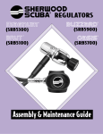
1
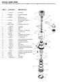
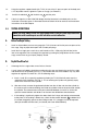
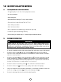
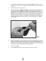
®
REGULATORS
®
(SRB5600)
Assembly & Maintenance Guide
FIRST STAGE - MAXIMUS™ SRB5600
The model number of the regulator is laser stamped on the first stage between two of the outlet ports.
ITEM #
1
2
3
4
CATALOG #
. . . . . . . . . . .5105-70
. . . . . . .J2790056B .
. . . . . . . . . . .1390-7
. . . . . . . .29-5305-4 .
.
.
.
.
.
.
.
.
.
.
.
.
DESCRIPTION
.
.
.
.
.
.
.
.
.
.
.
.
.
.
.
.
.
.
.
.
5 . . . . . . . .19-8010-8 . . . . . . . . .
6 . . . . . . . . . .G007A . . . . .
7 . . . . . . . . MS28774-007 .
8 . . . . . . . . . . .5705-20 . . .
9 . . . . . . . . .1-1665-17 . . .
10 . . . . . . .70-1665-26 . . .
11 . . . . . . . . .G904A . . . .
12 . . . . . . . .1-3405-4 . . . .
13 . . . . . . . .70-5705-1 . . . .
14 . . . . . . . . .G011B . . . . .
15 . . . . . . . . . .3106-6 . . .
16 . . . . . . . .1-3105-6 . . . .
17 . . . . . . . . . .5105-6 . . .
18 . . . . . . . . . .5105-15 . . .
18 . . . . . . . . . .5105-13 . . .
18 . . . . . . . . . .5105-14 . . .
19 . . . . . . . . . .5105-12 . . .
20 . . . . . . . . . .5105-PK . .
21 . . . . . . . . .G007A . . . . .
22 . . . . . . . . . .3801-5 . . .
23 . . . . . . . . . .5105-3 . . .
24 . . . . . . . . .G022A . . . . .
25. . . . . . . . .G025A . . . . .
26 . . . . . . . .70-5305-2 . . . .
27 . . . . . . . . . .5700-15 . . .
28 . . . . . . . . . .5705-21PE
.
.
.
.
.
.
.
.
.
.
.
.
.
.
.
.
.
.
.
.
.
.
.
.
.
.
.
.
.
.
.
.
.
.
.
.
.
.
.
.
.
.
.
.
.
.
.
.
.
.
.
.
.
.
.
.
.
.
.
.
.
.
.
.
.
.
.
.
.
.
.
.
.
.
.
.
.
.
.
.
.
.
.
.
.
.
.
.
.
.
.
.
.
.
.
.
.
.
.
.
.
.
.
.
.
.
.
.
.
.
.
.
.
.
.
.
.
.
.
.
.
.
.
.
.
.Handwheel
.Filter Retaining Ring
.Filter
.Moving Orifice
(bare, no O-rings)
.Belleville Spring Washers
(5 needed)
.O-ring
.White Backup Washer
.Dust Cap
.Yoke Nut
.Yoke
.O-ring (for H. P. port plug)
.H. P. Port Plug
.Body
.O-ring (for L.P. Port Plugs)
.One Way Bleed Valve
.L. P. Port Plug
.Gasket for Flow Control Element
.Restrictor Assembly
.Flow Restrictor Screw
.Filter
.Main Spring
.Shim (to raise hose pressure)
.O-ring (for small end of piston)
.Piston Seat
.Piston (bare, no seat or O-rings)
.O-ring (for large end of piston)
.O-ring (for cap)
.Cap
.Cap Label
.Trim Ring
TABLE OF CONTENTS
Page
1.0
Introduction . . . . . . . . . . . . . . . . . . . . . . . . . . . . . . . . . . . . .1
2.0
2.1
Specifications . . . . . . . . . . . . . . . . . . . . . . . . . . . . . . . . . . .3
SRB5600 (Maximus) . . . . . . . . . . . . . . . . . . . . . . . . . . . . . . .3
3.0
O-rings Reference Chart . . . . . . . . . . . . . . . . . . . . . . . . . . .4
4.0
4.1
4.2
4.3
4.4
First Stage Procedures . . . . . . . . . . . .
Tools Required for First Stage Servicing
Disassembly of First Stage . . . . . . . . . .
Assembly of First Stage . . . . . . . . . . . .
Testing of First Stage . . . . . . . . . . . . . . .
.
.
.
.
.
.
.
.
.
.
.
.
.
.
.
.
.
.
.
.
.
.
.
.
.
.
.
.
.
.
.
.
.
.
.
.
.
.
.
.
.
.
.
.
.
.
.
.
.
.
.
.
.
.
.
.
.
.
.
.
.
.
.
.
.
.
.
.
.
.
.5
.5
.5
.9
.10
5.0
5.1
5.2
5.3
5.4
5.5
Second Stage Procedures . . . . . . . . . . .
Tools Required for Second Stage Servicing
Disassembly of Second Stage . . . . . . . . . .
Assembly of Second Stage . . . . . . . . . . . .
Set-Up of Second Stage . . . . . . . . . . . . . .
Testing of Second Stage . . . . . . . . . . . . . .
.
.
.
.
.
.
.
.
.
.
.
.
.
.
.
.
.
.
.
.
.
.
.
.
.
.
.
.
.
.
.
.
.
.
.
.
.
.
.
.
.
.
.
.
.
.
.
.
.
.
.
.
.
.
.
.
.
.
.
.
.
.
.
.
.
.
.
.
.
.
.
.
.
.
.
.
.
.
.12
.12
.12
.14
.16
.18
6.0
6.1
6.2
6.3
6.4
Helpful Hints . . . . . . . . . . . . . . . . .
Troubleshooting . . . . . . . . . . . . . . .
Parts Cleaning Recommendations . .
Commonly Used Cleaning Solutions
Handling Tips . . . . . . . . . . . . . . . . .
.
.
.
.
.
.
.
.
.
.
.
.
.
.
.
.
.
.
.
.
.
.
.
.
.
.
.
.
.
.
.
.
.
.
.
.
.
.
.
.
.
.
.
.
.
.
.
.
.
.
.
.
.
.
.
.
.
.
.
.
.
.
.
.
.
.20
.20
.22
.22
.23
7.0
7.1
7.2
Two Year Warranty and Maintenance Information . . . . . . .24
Proper Procedure for Warranty Paperwork . . . . . . . . . . . . . .24
Scheduled Maintenance . . . . . . . . . . . . . . . . . . . . . . . . . . . .24
.
.
.
.
.
.
.
.
.
.
.
.
.
.
.
.
.
.
.
.
.
.
.
.
.
.
.
.
.
.
BEFORE YOU BEGIN.....
READ THESE INSTRUCTIONS COMPLETELY BEFORE YOU BEGIN SERVICING THE
REGULATOR.
THESE INSTRUCTIONS ARE INTENDED FOR PEOPLE WHO HAVE BEEN AUTHORIZED BY
SHERWOOD TO REPAIR SHERWOOD SCUBA EQUIPMENT. IF YOU ARE NOT SO
AUTHORIZED - STOP.
1.0 INTRODUCTION
1.
The procedures in this manual apply to the Sherwood Scuba SRB5600 Maximus regulator
only. The older SRB3600 Maximus regulator has different parts and service procedures. The
SRB3600 has its own service manual. The correct service manual for the two models can be
determined by looking at the cover picture of the regulator. The most current part numbers can
be obtained by referring to the dealer price guide, or calling your Sherwood Sales
Representative.
WARNING
Proper torque for the hose fittings is 40 in. lbs. (4.5 joules). NEVER tighten the hose fitting to the first stage with more than 45 in. lbs. (5 joules) of torque. The inlet hose fitting
can be weakened by overtightening. Failure of the fitting could cause air loss resulting
in death, personal injury, or property damage.
All current Sherwood Scuba Regulators have service kits available which contain the parts
which must be changed at every annual service no matter what their condition. The standard
annual service kit for the Maximus is 4000-4. All other parts not contained in this kit must be
inspected by the technician and changed under warranty only if they have failed due to
problems with material or workmanship.
NOTE: Oxygen Enriched Air conversion kits are available for all current Sherwood regulators and valves.
The part number for the model covered in this manual is 4000-15N. These kits are to be installed into
properly cleaned and prepared regulators only by technicians trained by one of the major oxygen enriched
air training agencies.
2.
This manual gives breakdowns of regulator parts, equipment specifications, servicing
instructions, troubleshooting recommendations, and guidelines for proper care of the SRB5600
Maximus regulator. This manual is intended for use only by persons specially trained and
authorized to service Sherwood Scuba equipment.
3.
Anyone attempting to service or repair Sherwood Scuba regulators must have a thorough
understanding of the principles of operation of scuba regulators and valves, as well as the
appropriate mechanical ability. The technician must be properly trained in the safe use of
compressed air and the various tools and cleaning solutions involved in the procedures
outlined in this manual.
4.
The best source for current part numbers for any of the parts listed in this manual is your
current parts and price list from Sherwood.
5.
Because of the many unique features found in Sherwood regulators, Sherwood conducts
seminars on a regular basis throughout North America to train technicians in proper service and
repair procedures for all current Sherwood regulators. In addition, all Sherwood dealers and
their staff members are encouraged to attend the seminars to gain an in-depth understanding
of the construction, special features and operation of Sherwood regulators. For information on
the dates and locations of upcoming Sherwood service seminars near you, contact
Sherwood or your Sherwood Sales Representative.
NOTE: You must be authorized by Sherwood to work on Sherwood Scuba equipment. You can obtain
proper authorization by attending all appropriate seminars given in your area. This is the only way you can
become an authorized Sherwood technician.
1
6.
Companion instructional VHS videotapes to this and other Sherwood Scuba repair manuals are
available from Sherwood Scuba at a nominal cost. Ask your Sherwood Scuba Sales
Representative for details.
7.
If you have any questions, or need more information, contact your Sherwood Scuba Sales
Representative.
2
2.0 SPECIFICATIONS
2.1
SPECIFICATIONS FOR THE SRB5600 MAXIMUS
REGULATOR MODEL:
AIR FLOW:
INHALATION RESISTANCE:
EXHALATION RESISTANCE:
RECOMMENDED LUBRICANT:
A.
First Stage Regulator:
TYPE:
WEIGHT:
INTERSTAGE PRESSURE:
MAXIMUM INLET PRESSURE:
POSITIVE AIR PURGE
FLOW RATE:
# LOW PRESSURE PORTS:
# HIGH PRESSURE PORTS:
MATERIALS:
B.
Sherwood SRB5600 Maximus
33 cu. ft. (935 liters)/min. @ 1 atmosphere
.9" - 1.5" (2.3 - 3.8 cm) w.c @ 1 atmosphere (adjustable)
0.7" (1.8 cm) w.c. max. @ 1 atm.
Christo-Lube® MCG111 (Sherwood p/n SW-MS150)
Flow-by piston with Moving Orifice Balancing, Dry Air
Bleed, and Air Sensing Channel Boost – U.S. Pat. #
4,226,257, U.S. Pat. #5,662,100
1 lb. 11 oz. (.77kg)
135 -150 psi (9-10 bar)
300 bar ( with 300 bar DIN adapter )
13-27 cc/minute
5 (3/8"-24 UNF)
2 (7/16"-20 UNF)
Body – CDA-36000 Brass
O-rings – Buna-N (Viton Nitrox o-ring kit available)
Bleed Valve – Ethylene Propylene
Piston Seat – Teflon®
Second Stage Regulator:
TYPE:
WEIGHT:
HOSE LENGTH:
MATERIALS :
Downstream valve, diaphragm, Variable Fulcrum –
U.S. Pat.#3,991,785 other Pat. pending
7.1 oz. (.22 kg) ( w/o hose)
41 in. (1.04 m)
Cover –Thermoplastic vinyl
Case –Thermoplastic Triax®
Poppet Seat – Buna-N
O-Rings – Buna-N
Diaphragm – Tufel® (clear blue)
Exhaust Valve – Thermoplastic elastomer (blue)
Mouthpiece – Liquid Silicone
3
3.0 O-RINGS REFERENCE CHART
1.
Before you begin disassembly of the regulator, test the first and second stages for output
pressures and leakage. Pre-testing in this way will help the technician to pinpoint any specific
problems requiring repair.
2.
The work area must be clean and well lighted, with clean compressed air available to blow
sand and dirt from parts.
4
4.0 FIRST STAGE PROCEDURES
4.1
TOOLS REQUIRED FOR FIRST STAGE SERVICING
– Bench vise
– 3/32" Allen wrench
– 5/32" Allen wrench
– 6" or 8" adjustable wrenches
– 15" adjustable wrench
– Phillips screwdriver
– #10 Torx screwdriver
– Sherwood 50 cc Graduated Cylinder (p/n TL110)
– Sherwood Piston Seat Removal Tool (p/n TL112)
– Sherwood Plastic Probe (p/n TL111) to push out orifice
– Sherwood Regulator Support Handle (p/n TL113)
– Sherwood Intermediate Pressure Gauge (p/n TL119)
– Annual Service Kit #4000-4 (same as older style Maximus)
– Nitrox Conversion Kit #4000-4N
– Christo-Lube® (p/n SW-MS150), 2 oz. tube of oxygen compatible lubricant
NOTE: For more information on Sherwood tools and their uses, see Sherwood’s Tools, Repair Kits and
Accessories - Assembly & Maintenance Guide, available from Sherwood.
4.2
DISASSEMBLY OF FIRST STAGE
To view all the parts used in the first stage, fold out the front cover of this manual. The
circled numbers below refer to the corresponding numbers on the drawing.
1.
Use 6" or 8" adjustable wrenches to disconnect all hoses from the first stage. Pull back the
hose protector from the inlet end of the hose. Inspect the hoses for wear. Pay particular attention
to the area where the metal ferrules meet the rubber hose material. Replace hoses if necessary.
2.
Unscrew and remove the handwheel 1 .
3.
Remove the dust cap 8 .
5
4.
Install a Sherwood regulator support handle (p/n TL113) into one of the low-pressure ports. Use
the support handle and a 15" adjustable wrench or bench vise to loosen the yoke nut 9 from
the body 13 . See Photo #1.
Photo #1
5.
Remove the yoke 10 and yoke nut 9 from the body.
6.
Use a 5/32" Allen wrench to remove all remaining port plugs 12 16 from the body.
7.
Use the Sherwood regulator support handle and a 15" adjustable wrench or a bench vise to
remove the cap 26 from the main body. The trim ring 28 will slide off at this time.
8.
Remove the spring 19 , any shims 20 , and the piston assembly 23 from the cap. Remove
both piston O-rings and discard them.
9.
Remove the piston seat 22 by pushing through the stem with the Sherwood piston seat
removal tool (p/n TL112) from the large end. The seat will then pop out. Discard the old seat.
10.
Using a 3/32" Allen wrench, remove the flow control element assembly 18 from inside the large
end of the main body. There are two styles of flow control assemblies. The old style with a
sintered stainless steel flow restrictor and the new style flow restrictor that is laser drilled P/N
5105-13 with a white filter P/N 5105-14. The new style complete assembly part number is
5105-15. If the regulator has the old style flow restrictor and it is functioning (13 to 27 cc/min) it
can be reused, however if it needs to be replaced use the new style. The black gasket can be
reused. The new style restrictor can be cleaned if it becomes plugged. Remove the white filter
and discard it. The white filter must be replaced P/N 5105-14. The laser drilled flow restrictor
can be cleaned in an ultrasonic cleaner and reused. The flow requirement for the new flow
control assembly is 20 to 30 cc/min.
6
Photo #2
Note:
If no air is bubbling from the one-way bleed valve, this is a good indication that the
positive air purge system is not working.
11.
Use a pocket screw driver to remove the black washer 17 that was beneath the element
assembly. Save this washer as it can usually be reused. Be careful not to scratch the metal
surface under the washer.
12.
Use a pocket screwdriver to remove the retaining ring or star washer 2 that holds the inlet
filter 3 in place. Always discard the used inlet filter. The retaining ring is saved for reuse.
13.
Remove the moving orifice assembly 4 from the body by pushing it with the Sherwood plastic
probe (p/n TL111) from the large threaded end of the body. Catch the orifice assembly in your
hand as it comes out the yoke nut thread end of the body. Carefully inspect the disc springs 5
for any cracks. Replace all five disc springs if any cracks are found.
14.
Remove the one way bleed valve 15 from the body with your fingers or a soft plastic probe.
DO NOT use a metal screwdriver or blade since this will scratch the sealing surface against
which the bleed valve seals. A scratch may allow water to enter the first stage spring chamber
during use.
7
The sealing surface on the body where the one-way valve seals must be totally clean of
deposits. If any deposits remain on the sealing surface after initial cleaning, take a fine abrasive
polishing stick or and polish the surface to remove deposits (see Photo #3).
Photo #3
15.
Blow all residue from the body after polishing.
16.
Remove the large O-ring 25 from the cap 26 . This O-ring can usually be reused.
17.
If necessary, clean all metal parts of the first stage except the flow control element assembly
18 in an ultrasonic cleaner or cleaning solution. Remove the O-rings before cleaning any metal
parts; most cleaning solutions can damage the O-ring material. See Section 6.3 for
recommendations on cleaning solutions. If major visible corrosion or deposits exist on parts,
use a bristle brush, wooden, or plastic stick to rub the deposits off. Allowing acidic cleaning
solutions to do all of the work if deposits are severe, will result in damage to internal chrome
plating which will make parts even more susceptible to future corrosion.
18.
Remove the regulator parts from the cleaning solution. Blow all internal passageways dry with
clean, dry compressed air.
19.
Inspect the bores in which the piston and orifice O-rings move for corrosion or wear. If the
bores are leaking air because of wear, replace the parts. If some corrosion deposits persist,
carefully wipe them away with a plastic scrubbing cloth. Blow any resulting dust out of the
regulator parts.
20.
Remove and discard the black O-ring from the moving orifice 4 . Save the white backup
washer; it can be reused. Inspect the moving orifice’s sealing surface (located at the top edge
of the orifice cone). Any nicks, scratches, or corrosion at the top of the cone can allow air to
pass, which will result in creeping hose pressures. Polish out the defects using a fine abrasive
polishing stick or pencil eraser. When polishing, apply a light pressure to prevent excessive
wear on the cone. Use compressed air to blow away any dust created by the polishing
process.
8
4.3
ASSEMBLY OF FIRST STAGE
1.
The part number for each regulator kit can be found in Sherwood’s Tools, Repair Kit and
Accessories – Assembly & Maintenance Guide. The kits contain the parts that are always
replaced at every annual service interval. The kit number for the Maximus is 4000-4. For Nitrox
use, the kit # is 4000-4N.
2.
Before installing new O-rings on the piston and moving orifice, lubricate the O-rings with
Christo-Lube MCG111 (Sherwood p/n SW-MS150). Installation of the small O-ring 21 on the
piston is made much easier by using the white-colored Sherwood O-ring installation cone (p/n
TL109). Place the cone over the tip of the piston. Slide the lubricated O-ring over the cone until
it slips into the piston groove.
3.
Place the new piston seat on a clean piece of paper on a hard flat surface. Press the piston tip
firmly over the seat until it is fully installed. The piston is now rebuilt and ready for installation.
4.
Use the Sherwood installation cone to prevent damage to the new O-ring during installation
onto the moving orifice. Use the green O-ring installation cone (p/n 28-TL107) to install first the
new O-ring 6 and then the used backup washer 7 onto the groove on the moving orifice.
Position them so that the black O-ring is closest to the wide end of the moving orifice.
5.
Using a greased soft probe, lightly lubricate the first 1/8" of the small bore in the body 13
where the small piston and moving orifice O-rings seal.
6.
With your finger, push the moving orifice assembly, pointed orifice end first, into the yoke end
of the main body as far as possible. Place the inlet filter 3 , rough side up, on top of the
moving orifice. Place the retaining ring or star washer 2 on top of the filter. Push the retaining
ring or star washer firmly into place with a dowel or screwdriver.
7.
Install the used black washer 17 into the hole in the main body where the flow element is
placed. A new washer may be installed if necessary.
8.
Install the flow control element 18 into the main body. Tighten the element with a 3/32" Allen
wrench with a torque of 3 in. lbs. (.4 nm). Do not overtighten.
9.
Replace the cleaned and lightly lubricated O-ring 25 on the cap 26 .
10.
Install the piston assembly 23 squarely into the cap 26 . If any shims were found when the
regulator was disassembled, place them over the piston stem. Then place the main spring 19
over the piston stem. Install the trim ring 28 onto the body.
11.
Install the cap assembly onto the body. Hand-tighten the assembly as tightly as possible, then
install the Sherwood regulator support handle into one of the low pressure ports. Using a 15"
adjustable wrench or a bench vice to hold the cap, tighten the cap onto the body until it
bottoms on the thread. Do not tighten further.
12.
Using your index finger, install the clean and dry one-way bleed valve 15 into the body.
NOTE: If you use the bleed valve with the Sherwood logo molded into it P/N 3106-6 you will notice a
"dot" molded near the right side of the logo. Install the bleed valve with the "dot" oriented closest to the
inlet of the regulator (towards the yoke).
13.
Lightly lubricate the body yoke nut threads with grease, and install the yoke 10 and the yoke
nut 9 onto the body.
9
14.
15.
Using the regulator support handle (p/n TL113) in one of the LP pressure ports of the body and
a 15" adjustable wrench, tighten the yoke nut snugly (see Photo #1).
Install the handwheel 1 and the dust cap 8 onto the yoke.
16.
If the first stage has a SAA-5300 DIN adapter installed instead of a standard yoke, see the
installation instructions given in Sherwood Technical Bulletin #104 for overhaul and installation
instructions of the DIN adapter.
4.4
TESTING OF FIRST STAGE
NOTE: For safety, always test the first stage regulator with at least one second stage installed.The
demand valve on the second stage acts as a relief valve in the event of a malfunction.
A.
Before You Begin Testing
1.
Install an intermediate pressure test gauge (p/n TL119) into one of the low pressure ports of the
first stage. Plug any open outlet ports with suitable port plugs.
2.
Install the first stage onto a tank valve, and introduce 2700 - 3500 psig (186-240 bar) to the
inlet of the regulator. Flow air through the regulator by pushing the purge button on the second
stage several times to get all parts properly seated.
B.
Dry Air Bleed Flow Test
1.
Submerge the first stage under several inches of water.
2.
A small stream of bubbles should be escaping from the one-way bleed valve on the first stage
and nowhere else on the body (see Fig. 1). The number and size of the bubbles may vary from
regulator to regulator. To check this, use the following steps:
a.
Invert a small (50 cc capacity) graduated cylinder (p/n TL110) filled with water over the
underwater flow of bubbles (see Fig. 1). The air entering the cylinder will gradually empty
some of the water out of the cylinder.
b. After one minute, remove the graduated cylinder from the air flow and raise the cylinder to
the surface so that air/water dividing line inside the cylinder matches the water level outside
the cylinder. The measurement at this point should be between 13 and 27 cc for the old
style flow control element and 20-30 cc for the new laser drilled flow control element.
c.
If the reading is significantly higher than 30cc check the O-rings and sealing surfacesmated
to the piston. If the reading is below 13cc, check the flow control element 18 to determine if
it has been clogged by grease or other foreign matter. If it is clogged, it must be replaced
(old style sintered stainless steel ) or cleaned (new laser drilled element).
10
C.
Intermediate Pressure Test
NOTE: This test determines the regulator’s lock-up pressure (the pressure put out by the first stage during
a no-flow condition).
1.
Attach any Sherwood second stage to one of the low pressure ports, and the Sherwood
intermediate pressure gauge (p/n TL119) to another low pressure port. Plug all other ports with
appropriate port plugs.
2.
Attach the regulator to a tank valve giving a source pressure of between 2700 and 3500 psig
(186 and 240 bar).
3.
Turn the supply air on slowly while listening for any unusual air leaks. If any are heard, turn
the air off immediately and determine the source of the leak. If no leaks are found, watch the
pressure gauge reading rise as you continue turning the air on slowly. It should stop around
145 psig (10 bar).
4.
If the pressure gauge continues to rise above 155 psig (10.4 bar), turn the air supply off
immediately and inspect the regulator to determine the cause.
5.
Once the air pressure stops rising, the internal parts should be worked into place by allowing
air to escape from the second stage several times by pushing the purge button.
6.
If you have depressed the purge button several times and the pressure is below 135 psig (9.3
bar), you can add shims 20 to increase the pressure. Do not use more than three shims.
7.
If the pressure is too high (above 150 psig or 10.3 bar), remove the necessary shims.
8.
After the correct pressure has been reached, let the regulator sit for several minutes and then
depress the purge button again to check that the regulator returns to the proper pressure.
Never set the output pressure of the first stage above 150 psig (10.3 bar).
11
5.0 SECOND STAGE PROCEDURES
5.1
TOOLS REQUIRED FOR SECOND STAGE SERVICING
– Two good quality 6" or 8" (15 or 20 cm) adjustable wrenches
– #10 Torx screwdriver
– Side cutting pliers
– Sherwood Plastic Probe (p/n TL111) to push out orifice
– Sherwood Lever Height Adjusting Tool (p/n TL123)
– Small Phillips screwdriver
– Small slotted screwdriver
– Size "0" square drive screwdriver (e.g. Channel Lock p/n SL-0)
– Locktite 242® (mild thread locking adhesive)
– Christo-Lube® (p/n SW-MS150), 2 oz. tube of oxygen compatible lubricant
5.2
DISASSEMBLY OF SECOND STAGE
WARNING
Proper torque for the hose fittings is 40 in. lbs. (4.5 Joules). NEVER tighten the hose
fitting to the first stage with more than 45 in. lbs. (5 Joules) of torque. The inlet hose
fitting can be weakened by overtightening. Failure of the fitting could cause air loss
resulting in death, personal injury or property damage.
To view the complete parts list of the second stage, fold out the back cover of this manual.
1.
Remove the hose assembly 3 from the swivel fitting 10 . Inspect the hose assembly for
any cuts or cracks, especially on the hose at the metal ferrules. Replace the hose assembly if
any cuts or cracks are found.
2.
Remove the mouthpiece 22 by cutting the mouthpiece tie 21 with side cutting pliers. Discard
the old mouthpiece tie. Examine the condition of the mouthpiece. Pay particular attention to
the area on top just behind where the old tie tightened. This is a prime area for small holes to
develop. If the mouthpiece is in good condition, it can be reused.
3.
Remove the exhaust tee retaining screws 28 with a #10 Torx or slotted screwdriver.
4.
Remove the exhaust tee 38 from the case by pulling it back and off the top edge.
5.
Using a size 0 Square Drive Screwdriver (preferred) or a small Phillips Screwdriver, loosen and
remove the screw 5 and washer 6 from the orifice Adjusting Knob 7 .
6.
Remove the adjusting knob from the end of the adjusting orifice.
12
7.
Using a small slotted screwdriver, remove the cir-clip 4 from the adjusting orifice 16 .
8.
Use a 5/8" wrench to remove the retainer nut 9 from the orifice housing 13 . Hold the base of
the orifice housing with a 3/4" wrench while doing this.
9.
Remove the swivel fitting 10 from the orifice housing. Inspect the inner sealing surfaces for
scratches that might cause leaks.
10.
Remove the cover 17 from the case by pushing on the front top edge firmly enough to cause
the top lip of the cover to curl outwards. Use fingers to grasp the exposed lip of the cover.
Slide the cover assemble off of the orifice housing.
11.
Remove the diaphragm retaining ring 18 from the case using fingers.
12.
Gently remove the diaphragm 19 from the case. Hold the diaphragm up to a light source.
Gently stretch the diaphragm and look for tears or pinholes. If any are found, replace the
diaphragm. Otherwise, the diaphragm can be reused. If you are repeatedly tearing diaphragms
during this visual inspection, you are using too much force. You cannot return diaphragms torn
in this way for warranty credit.
13.
Remove the adjusting lever 25 from the case by using a small slotted screwdriver to slide the
retainer clip 23 , off the adjusting lever. Slide the adjusting lever out of the case 20 . The
adjusting lever and o-ring 24 can usually be cleaned by hand in warm soapy water,
relubricated, and reused with the o-ring in place. However, if the o-ring 24 shows excessive
wear it can be removed and discarded at this time. Use a blunted dental pick or similar object
to remove the o-ring if removal is necessary. Take care not to gouge the o-ring groove during
this procedure.
14.
Use a 6" or 8" (15 or 20 cm) adjustable wrench to loosen and remove the orifice housing 13 .
The case assembly has been reinforced to allow doing this without holding the lever support
with another wrench.
15.
Remove the lever support 32 and assembly from the case with the heat transfer fins 34 & 35
still attached. There is no reason to remove these fins from the lever support during a normal
service interval. If the fins do have to be removed for some reason, a small Phillips ACR
screwdriver can be used to remove and replace the screws 28 .
16.
Normally, along with cleaning, you will simply need to change the poppet stem seat insert 29
and polish the orifice seal 16 , to restore the second stage to maximum performance. To
change the stem seat insert 29 , leave the lever assembly together. With a pick or similar
object, carefully remove the old seat insert. Put the new seat insert on a clean flat surface and
lower the poppet cavity (from which the old seat insert was removed) over the new seat insert.
The new style black molded seat (p/n 978-9BN) should be installed with the identifying
Sherwood symbol facing outward.
17.
If parts of the lever assembly (stem, spring, lever, etc.) need to be replaced, it can be done with
a minimum number of tools. With the original poppet seat 29 in place, and the orifice 16
installed in the orifice housing 13 , screw the orifice housing and lever support together
(without the case) until the lever begins to droop. Use a #10 Torx screwdriver to remove the
screw 37 . Unscrew the orifice housing and lever support, and the poppet and spring will be
exposed for replacement. Reverse the procedure to install the new parts. Remember to use the
old seat to perform this procedure since the seat is likely to be damaged due to excess friction.
Install a new seat 29 when you have reassembled the lever assembly.
13
NOTE: If only the lever 36 is to be replaced, do not totally remove the screw. You can remove the lever
from under the screw 37 when the screw is almost all the way out.
18.
Hold the orifice housing 13 in one hand. Temporarily install the adjuster knob 7 and use it to
turn the orifice clockwise until it comes out of the orifice housing. Remove and discard the
o-rings on the orifice 14 & 15 , and the orifice housing 11 & 12 .
19.
Before removing the exhaust valve 26 from the case, bend it over as far as it will go from the
top, bottom, left and right sides. If it fails to snap back quickly, and does not lie perfectly flat
against the case, the valve should be replaced. If it does snap back satisfactorily, remove it and
inspect the sealing edges. If they appear smooth, and the locking tab on the nipple is good, the
valve can be reused.
20.
Rinse all plastic and silicone parts in clean fresh water, and then blow the parts dry with
compressed air to remove any sand and dust particles.
21.
If necessary, clean all metal parts of the second stage in an ultrasonic cleaner or cleaning
solution. Remove the o-rings before cleaning any metal parts; most cleaning solutions are
damaging to the o-ring material. See Section 6.3 for recommendations on cleaning solutions.
NOTE: If you use an ultrasonic cleaner to clean the second stage adjustable orifice 16 , use a plastic
container to prevent the orifice from vibrating against other metal parts which could damage the orifice seal.
22.
Inspect the case 20 for any cracks. Look particularly closely at the area where the orifice
housing and the lever support clamp down. Replace the case if any cracks are found.
23.
Inspect the sealing surface on the orifice 16 (where the poppet insert seals) for any nicks,
scratches, or corrosion. Corrosion or minor scratches can be polished out using a fine-grit
rubberized polishing stick or a clean new pencil eraser. Do not apply heavy pressure when
rotating the polishing stick. Stop polishing immediately after the corrosion or scratch
disappears. An orifice will not be accepted for warranty replacement simply because it is dirty
or corroded. The technician must clean the orifice sealing surface at every service interval.
24.
Blow all dust and debris out of the orifice housing with clean compressed air.
NOTE: Prior to this point, you should have cleaned and inspected all parts, following proper servicing
procedures. Do not continue until this has been done.
5.3
ASSEMBLY OF SECOND STAGE
1.
Install the exhaust valve 14 into the case by inserting the nipples into the small holes from the
outside of the case. Reach inside the case and pull the nipple firmly with the fingers until you
hear or feel it “click” into place. Inspect the exhaust valve to see that it is properly seated.
2.
Install the lever support 32 and assembly into the case, setting it firmly between the guide ribs
in the Case.
3.
Lubricate and install new o-rings 14 & 15 from the annual service kit onto the orifice 16 . Install
the orifice back into the orifice housing 13 using the fingertip. Use the adjustor knob to turn the
orifice counter-clockwise fully, until it stops.
14
4.
Screw the orifice housing 13 onto the threads of the lever assembly. Using a 3/4" wrench on
the orifice housing tighten them together snugly (70 in. lbs., 7.8nm).
NOTE: A drop of mild thread locker, such as Locktite 242® or equivalent should be applied to the threads
of the lever support to prevent the Orifice Housing from loosening during use.
5.
Lubricate and install new o-rings 11 & 12 from the annual service kit onto the orifice housing
Note that the larger of the two o-rings goes on the end of the housing closest to the case.
6.
Install the cover 17 onto the case by sliding the retaining loop over the orifice housing. Since
the inner parts of the case have not yet been installed, the cover is rotated on the orifice
housing out of the way at this time.
7.
Lightly lubricate the inner bore of the swivel fitting with the recommended grease. Install the
swivel fitting onto the orifice housing.
8.
Install the retainer nut 9 onto the orifice housing thread. Tighten the retainer nut snugly.
(70 in. lbs., 7.8 nm)
9.
Install the cir-clip 8 onto the orifice.
10.
Install the adjusting knob 7 onto the orifice.
11.
Install the washer 6 onto the screw 5 . Place a small drop of locking adhesive onto the
threads of the screw, and install it snugly into the orifice using a size 0 square drive or Phillips
screwdriver.
NOTE: Do not allow lubrication (grease on fingers, silicone overspray, etc.) to get on the case 20 , the
diaphragm 19 , the retaining ring 18 , or the exhaust valve 26 . This may cause these parts to slip or
deteriorate.
12.
If the old o-ring 24 on the adjusting lever 25 was replaced due to wear, lubricate and install a
new one onto the adjusting lever. If the o-ring is not worn, in can be lubricated in place on the
adjusting lever. Install the adjusting lever into the case 20 . Using a small slotted screwdriver,
install the retainer clip 23 onto the adjusting lever in its groove inside the case. Move the
adjusting lever through its full range. Check that the fins 34 & 35 move freely in the mouthtube
area. If they touch the top or bottom of the mouthtube and hang-up, rotate the lever support 32
slightly until the fins move freely. If the fins do not follow the adjusting lever tip through the
entire stroke, rebend the fins slightly to create the proper tension to keep them against the
lever tip.
THE FOLLOWING STEPS (13-19) ARE INCLUDED HERE FOR CONTINUITY. THEY MUST BE
PERFORMED AFTER THE REGULATOR SECOND STAGE IS ADJUSTED (see Section 5.4, Set-Up of
Second Stage).
13.
Install the diaphragm 19 into the case so that it sits evenly on the ledge.
14.
Install the retaining ring 18 into the diaphragm recess.
15.
Work the cover 17 over the case until it sits properly in its groove in the cover.
15
16.
Install the exhaust tee 38 onto the case using the two screws 28 .
NOTE: Depending on the owner’s needs, either the Blizzard, Oasis and Maximus style extended tee 38 for
maximum bubble dispersion, or the Magnum/Brut style shorter tee 27 for minimum weight and drag, can
be installed on any of the three models.
17.
Tighten the exhaust tee screws 28 using a # 10 Torx screw driver just enough to seat them
snugly. There is no reason to turn these screws beyond the first contact point. Do not
overtighten. These screws are threaded into plastic, which will hold well in service but is easily
stripped if overtightened.
18.
Install the mouthpiece 22 . Be sure to position the mouthpiece so that the word “Sherwood” is
on the top.
19.
Install a new mouthpiece tie 21 . For diver’s comfort, be sure the clamp is on the side, not the
top or bottom.
20.
Install the hose 3 into a serviced first stage, and the second stage, tighten snugly.
WARNING
Proper torque for the hose fittings is 40 in. lbs. (4.5 Joules). NEVER tighten the hose
fitting to the first stage with more than 45 in. lbs. (5 Joules) of torque. The inlet hose fitting can be weakened by overtightening. Failure of the fitting could cause air loss resulting in death, personal injury or property damage.
5.4
SET- UP OF SECOND STAGE
For the following adjustments, remove the cover and diaphragm.
1.
Turn the adjuster knob 7 out counter-clockwise all the way.
2.
Use a # 10 Torx screwdriver to turn the poppet screw 37 counter-clockwise outward, until the
lever assembly 32 & 36 is just loose enough so that the tip of the lever will move loosely up
and down about 1/16”.
3.
Attach the second stage to the overhauled and properly adjusted first stage that it is going to
be used with, mounted on a air tank filled to between 2700 and 3500 psig. Install an
intermediate pressure gauge into one of the low pressure ports.
4.
Carefully turn the air on. With the lever 36 slightly loose against the lever support 32 , there
should be no air leaking from the second stage with proper intermediate pressure applied to
the hose. If there is air leaking from anywhere on the second stage, correct the problem before
going further.
5.
With the air turned on, use a #10 Torx screwdriver to turn the poppet screw 37 clockwise until
a slight hiss is heard coming from the second stage. Work the lever up and down a few times
to ensure that the slight hiss still exists when the lever is released This adjustment has just
lifted the poppet seat off the orifice seal area. This is the long term storage position (one week
or longer) for the adjustment knob 7 .
6.
Turn the knob 7 slowly clockwise. The hissing should stop by the time the knob is turned 1/8
to 1/4 of a turn clockwise. If the hissing does not stop by the time the knob has been turned
1/4 of a rotation clockwise, then inspect the orifice sealing area 16 and seat 29 for damage.
16
7.
If the hissing has stopped properly, continue turning the knob 7 clockwise until the stop is
felt. Breathe on the regulator. It should breathe fairly hard at this setting, but still deliver a good
air supply.
8.
Check the purge button for proper operation.
9.
After setting the poppet screw 37 and orifice 16 , the relationship between the diaphragm wear
plate and the tip of the lever 36 must be checked. To do this, install the diaphragm and
retaining ring. The tip of the lever should just barely touch the diaphragm. If when touching the
diaphragm lightly with the finger there seems to be a significant gap between the lever tip and
diaphragm, remove the diaphragm and bend the lever slightly upwards using the fingers. If the
regulator hisses slightly when the air is turned on, but stops hissing when the diaphragm is
removed, then the lever is too high. Use Sherwood’s lever bending tool (p/n 4005-16) to bend
the lever slightly downward as shown in Photo #5. There are two indentations at the proper
lever bend point.
Photo #5
10.
Replace the diaphragm and test the gap between the lever and the diaphragm again after each
bending. Lever bending is usually necessary only when a new lever is being installed in the
regulator. If you are re-using the same major parts of the regulator, this measurement will most
likely be correct, and no adjustment will be needed. In fact bending the lever should be avoided
unless necessary to get the tip of the lever in the proper position.
11.
Replace the cover 17 .
12.
Return to Section 5.3.13 of this manual to complete assembly of the regulator.
17
5.5
TESTING OF SECOND STAGE
A.
Inhalation Effort
1.
If you have no instrumentation, breathe on the regulator to test the breathing effort. With the
adjusting knob turned fully counter-clockwise a slight hissing free flow should be heard. The
hissing should stop when the knob is turned slightly clockwise. The breathing should be easy
at this point. Turn the knob fully clockwise. The inhalation should be more difficult, but the
purge button should still work.
2.
If a water column or water manometer is used to check inhalation effort, it should not exceed
1" w. c. at cracking with the adjustor knob in the minimum effort position. It should drop to
about 3/4" w. c. at one atmosphere and a moderate flow rate. The technician can alter the
inhalation effort within a certain range. The overall inhalation effort can be decreased by turning
the poppet screw 37 counterclockwise, and adjusting the intermediate pressure to the top end
of the range. However, counterclockwise adjusting must stop when the lever 36 becomes loose
against the lever support 32 . The overall inhalation effort can be increased by turning the
poppet screw 37 clockwise, and adjusting the intermediate pressure to the lower part of the
range. However, clockwise adjusting must stop when air begins to hiss past the second stage
Poppet. Note: This higher effort setting also gives the regulator its greatest resistance to
second stage freeze-ups in cold water diving.
3.
Move the venturi adjusting lever 25 through its full range of movement while inhaling on the
regulator. With surface air flows you will only be able to feel the air moving from a left to right
jetting in the mouth. At greater depths, the volume of air will increase to the point where
adjusting the lever to the “+” position (as indicated on the case) will cause a marked increase in
the venturi effect and subsequent air delivery.
B.
Exhalation Effort
1.
If you do not use instruments to check the exhalation effort, the flow should feel smooth and
unrestricted.
2.
If you use a water column, it should not exceed 1/2" w.c. (.02 bar) at one atmosphere.
3.
Brand new exhaust valves will sometimes adhere slightly to the case, causing a slight increase
in inhalation effort. This condition will disappear with use.
C.
Leak Test
1.
Disconnect the air supply. Purge the regulator of all positive air pressure.
2.
Slowly immerse the second stage in a pan of water with the mouthpiece pointing straight up.
3.
Immerse the regulator until the water is 1/4" to 1/8" (.64 to .32 cm) from the lip of the
mouthpiece.
4.
Hold the regulator in this position for one minute and then slowly raise it out of the water.
5.
Tip the regulator mouthpiece downward and watch the inside of the mouthpiece tube. If any
water escapes from the mouthpiece tube, check for source of leakage.
18
D.
Intermediate Pressure Air Leaks
1.
Attach the regulator first stage to a tank short enough to totally submerge the first and second
stage in your filling station cooling water. Adjust the breathing effort knob to the minimum
breathing effort position (not the slight freeflow position).
2.
With the tank valve still turned off, flood the second stage completely with water, and then
position it mouthpiece up.
3.
Turn the tank air valve on slowly and then watch for any leaks in the first or second stage
(except for the normal flow of air from the one-way bleed valve on the first stage).
4.
5.
Repair any leaks.
Check for the correct positive air purge flow rate. See Section 4.4, “Testing of First Stage,”
for the proper method.
19
6.0 HELPFUL HINTS
6.1
TROUBLESHOOTING REGULATORS
POSSIBLE CAUSE
RECOMMENDED ACTION
A. High Inhalation Effort at Depth:
1. Inlet filter clogged.
Replace the filter.
2. No air flowing through the dry air bleed system.
Check the flow rate coming out of the
one-way bleed valve 15 . If no or low
air flow is detected, replace the flow
element assembly 18 .
3. Air supply to first stage insufficient.
Verify the supply air pressure. Make
sure the customer had the air valve
turned all the way on during the dive.
4. Second stage improperly adjusted.
Repeat Steps 1 through 6 in Section
5.4, Set-Up of Second Stage.
B. Free Flowing:
1. Intermediate pressure too high.
Adjust intermediate pressure below
150 psi by removing shims 20 .
2. Damaged or worn first stage piston seat.
Replace piston seat 22 .
3. Damaged or worn second stage poppet seat.
Replace second stage poppet seat 29 .
4. Nicked or corroded orifice sealing surfaces.
Polish the orifice sealing surfaces in
both the first and second stages with a
pencil eraser or polishing stick. If
damage is too severe to polish out,
replace orifice 4 or 16 .
5. Second stage demand lever
Adjust or replace the lever.
bent too high.
6. Weak spring in second stage.
Replace the spring.
7. First or second stage improperly adjusted.
Refer to Sections 4.4 and 5.4 of this
manual.
8. Parts in the second stage have been severely
chilled due to repeated purging and have shrunk,
allowing air to flow.
Allow the second stage to warm back
up to room temperature. This chilling
will not occur in normal diving.
20
C. Wet Breathing:
1. Improper clearing, or diver diving in total
head-down position.
Instruct the diver on proper clearing
technique.
2. Leaking past adjusting lever 25 .
Install new o-ring 24 . Check sealing
surface & groove.
3. Diaphragm improperly installed or holed.
Check position of diaphragm visually.
Replace if holed.
4. Damaged or loose fitting exhaust valve
Replace exhaust valve 26 .
5. Crack in case 20 .
Replace case.
D. High Frequency Humming or Buzzing During Inhalation:
1. Harmonic resonance between the springs
and the mass of the piston in the first stage.
Disassemble the first stage and flip the
main spring over. Change the position
of the piston 23 in its bore. If
resonance is still present, install a new
piston and spring.
E. Low Frequency Fluttering During Inhalation (Above the Surface Only):
1. Harmonic resonance between the springs
and the mass of the second stage diaphragm.
21
Try adjusting the lever tip closer or
farther from the diaphragm wear plate.
Switch diaphragm with another unit.
Explain to the customer that this is not
harmful to the regulator, and does not
happen underwater.
6.2
PARTS CLEANING RECOMMENDATIONS
Regulators which see heavy use, particularly those used in salt water, often require extra effort
to remove dirt and corrosion from the parts of the regulator. Some suggested cleaning
solutions are listed at the end of this section, and there are probably many others being used
successfully. Here are a few general suggestions we can make:
1. Don’t expect your cleaning solution to do all the work in a matter of seconds. If the solution
cleans extremely rapidly, it is probably too strong and is etching the finish on the parts. Use a
wooden or plastic stick or a soft bristle brush to help get rid of the thickest deposits. Take
special care not to damage orifice sealing areas. Dress the orifice sealing areas with a fine grit
polishing stick or pencil eraser after drying the parts.
2. Immerse only those parts which really need cleaning. With Sherwood’s Dry Air Bleed System,
the interior of the first stage is always clean and dry, so the piston and spring should never
need cleaning. Always remove the flow control element in the first stage 18 from the body
before immersing the first stage in a cleaning solution. Immersing the body in a cleaning
solution can plug the flow control element, which could slow or stop the flow through the
positive air purge system.
3. Many of the solutions used for cleaning metal parts can damage the nitrite compounds
found in o-rings. For this reason, remove all o-rings before placing parts in a cleaning bath.
6.3
COMMONLY USED CLEANING SOLUTIONS
SOLUTION
COMMENTS
Soapy water
Good choice. Good for plastic, silicone
and plated metal parts.
Vinegar and water (equal part solution)
Ingredients easily available. Approx. 15
minutes cleaning time. May damage
chrome finish.
1000 cc water
60 gr. sulfuric acid
60 gr. potassium dichromate
Fast-acting solution that must be made
and used with care. Use gloves and
safety glasses. Can damage chrome
finish.
Cleaning solutions recommended
by ultrasonic cleaner manufacturers
The preferred choice. Check with the
manufacturer for strengths and
recommended uses for their cleaners.
Choose soap solutions over acidic
ones.
22
6.4
HANDLING TIPS
How your customers treat their regulators will directly influence the unit’s function and
durability. Following are a few tips that you can pass on to your customers to help assure the
durability of their Sherwood Scuba regulator.
A.
Pre-Dive Checks
1.
Check the hoses and hose connections for cuts, abrasions or other signs of damage before
mounting the regulator on the tank valve. Slide the hose protectors back to inspect the areas of
the hose normally covered. Be sure all hose connections are tight.
2.
Before turning on the tank air valve, check to make sure that the yoke nut or DIN connection is
tight and the regulator body is aligned properly, with no kinks in the hoses.
3.
Turn the tank valve on slowly and listen for leaks. If any leaks are found, replace or repair parts
as recommended.
4.
Never lift the tank/BCD assembly by the regulator or hoses.
5.
Just before mounting the regulator on the valve, always turn the valve on briefly to blow any
trapped water out of the valve. There is often saltywater trapping in the outlet side of the valve.
This entrapped salt water being blown through the interior of the regulator is the number one
source of internal corrosion and problems with the dry air bleed system.
6.
Surface-test the regulator by breathing lightly through the mouthpiece. Depressing the purge
button above the water’s surface is not an appropriate method for testing the function of the
regulator.
B.
Post-Dive Care
1.
After the dive, blow all water out of the dust cap with clean dry air and place the cap securely
on the regulator inlet. On multiple tank dives, use great care to keep salt water out of the
regulator inlet when tanks are changed. Neglecting these simple procedures is the greatest
cause of corrosion and wear in scuba regulators. When used properly, Sherwood’s exclusive
Dry Air Bleed System keeps all other water-borne contamination out of the first stage body.
NOTE: A tiny stream of air bubbles escaping from a small black valve on the first stage indicates that the
Dry Air Bleed System is working. The amount of air used is negligible (13 - 27 cc/min.). Check the system
periodically (see Section 4.3B in this manual), particularly after servicing, to ensure that there is some air
escaping from the black one-way bleed valve. If no air is escaping from the valve when air pressure is applied
to the first stage, have the regulator inspected.
2.
With the dust cap securely in place, rinse the first and second stages in clean fresh water. DO
NOT depress the purge button before or during rinsing since this may introduce water into the
second stage and the low pressure hose. Shake or blow all excess water from the second
stage and allow the entire regulator to air-dry before storing.
3.
Store the regulator in a clean bag or storage box, away from sunlight, excessive heat and
humidity.
23
7.0 TWO YEAR WARRANTY AND MAINTENANCE
INFORMATION
7.1
PROPER PROCEDURE FOR WARRANTY PAPERWORK
1.
For detailed information on the operation of the Sherwood Scuba Two Year Limited Warranty,
please refer to Sherwood Scuba Technical Bulletin #112. You can also contact your Sherwood
distributor if you still have questions about the warranty.
2.
In most situations, no paperwork will be necessary. The customer will bring his or her regulator
in for one of its two annual servicings under the warranty. No parts other than those contained
in the standard annual service kits will be needed. Discard all old parts replaced by new kit
parts. Please do not return these used parts to Sherwood Scuba!
3.
Remove one of the colored annual service rings from the main hose protector. When you have
collected several of these rings (25-50), contact Sherwood Customer Service for a Return
Goods Authorization Number. The color of the ring will determine the credit or type of service
kit you will receive.
4.
If you replace parts other than those contained in the standard annual servicing kit, you will
have to submit paperwork. If the regulator meets the conditions of the two-year warranty, and
the warranty is still active, fill out the Sherwood Warranty Replacement Parts Form. You must
describe the problem with the part you are returning in Part Five of the form. If this area is
blank, you will not receive credit for that part.
5.
For Sherwood Scuba regulators manufactured before Jan. 1, 1993 which still have a valid Lifetime
Limited Warranty, you, the dealer, must send the white Warranty Service Form to Sherwood. The
information will be recorded by Sherwood to determine whether or not the warranty on that particular
regulator is still in effect.
7.2
SCHEDULED MAINTENANCE
1.
To keep the owner warranty in effect, your customers must have their regulators inspected and
serviced annually (within 6 weeks before or after the anniversary of the date of purchase) by an
authorized Sherwood dealer. Failure to do so invalidates the warranty.
2.
Even with infrequent use, the regulator should be serviced annually to ensure proper
performance and satisfy warranty requirements.
3.
In Sherwood Scuba regulators manufactured before Jan. 1, 1993 which still have a valid
Lifetime Limited Warranty, you, the dealer, must send the white Warranty Service Form in to
Sherwood. The information will be recorded by Sherwood to determine whether or not the
warranty on that particular regulator is still in effect.
24
SECOND STAGE REGULATOR - MAXIMUS™ SRB5600
NOTE: Labels (Item 1 below) in white, purple, pink, green, blue and yellow are available.
ITEM #
CATALOG #
1 . . . . . . . . . . . G011B. . . . . . .
2 . . . . . . . . . . . . .5100-27 . . . .
3 . . . . . . . . . . . . .5016-20-41A
4 . . . . . . . . . . . G010A . . . . . .
5 . . . . . . . J12C04045B . . . . .
6 . . . . . . . . . .19-4600-17 . . . .
7 . . . . . . . . . . . . .5602-16 . . . .
8 . . . . . . . . . . . . .3602-35 . . . .
9 . . . . . . . . . . . 1-3602-15 . . . .
10 . . . . . . . . .70-5602-14 . . . .
11 . . . . . . . . . . G014C . . . . . .
12 . . . . . . . . . . G015C . . . . . .
13 . . . . . . . . .71-5602-13 . . . .
14 . . . . . . . . . . G006B . . . . . .
15 . . . . . . . . . . G011B . . . . . .
16 . . . . . . . . .29-5602-12 . . . .
17 . . . . . . . . . . . .5602-80 . . . .
18 . . . . . . . . . . . .5100-6 . . . . .
19 . . . . . . . . . . . .3108-13 . . . .
20 . . . . . . . . . . . .5602-1 . . . . .
21 . . . . . . . . . . . .3786-9W . . .
22 . . . . . . . . . . . .5602-3LS. . .
23 . . . . . . . . . . . .5602-3 . . . . .
24 . . . . . . . . . . G106B . . . . . .
25 . . . . . . . . . . . .5602-5 . . . . .
26 . . . . . . . . . . . .3602-6A. . . .
27 . . . . . . . . . . . .5700-9 . . . . .
28 . . . . . . . . . . . .3702-5 . . . . .
29 . . . . . . . . . . . .978-9BN . . .
30 . . . . . . . . .29-5700-1 . . . . .
31 . . . . . . . . . . . .5100-29 . . . .
32 . . . . . . . . . . 9-5100-3A . . . .
33 . . . . . J113481874BACR . .
34 . . . . . . . . .25-5700-21 . . . .
35 . . . . . . . . .25-5700-22 . . . .
36 . . . . . . . . .29-3108-3 . . . . .
37 . . . . . . . . . . G010A . . . . . .
38 . . . . . . . . . . . .5700-9BK . .
.
.
.
.
.
.
.
.
.
.
.
.
.
.
.
.
.
.
.
.
.
.
.
.
.
.
.
.
.
.
.
.
.
.
.
.
.
.
DESCRIPTION
..........
..........
..........
..........
..........
..........
..........
..........
..........
..........
..........
..........
..........
..........
..........
..........
..........
..........
..........
..........
..........
..........
..........
..........
..........
..........
..........
..........
..........
..........
..........
..........
..........
..........
..........
..........
..........
..........
O-ring (hose inlet end)
Hose Protector
Hose Assembly (41”-84cm), includes hose protector & o-rings
O-ring (for hose outlet end)
Screw (for adjuster knob)
Washer (for adjuster knob)
Adjuster Knob
Retaining Ring
Nut
Swivel Fitting
O-ring (smaller o-ring for orifice housing)
O-ring (larger o-ring for orifice housing)
Orifice Housing
O-ring (smaller o-ring for orifice)
O-ring (larger o-ring for orifice)
Orifice
Cover Assembly
Retainer Ring
Diaphragm (blue Tufel®)
Case
Mouthpiece Tie
Mouthpiece (special Wisdom® style mouthpiece for Maximus only)
Retainer Clip (for adjusting lever)
O-ring
Adjusting Lever
Exhaust Valve
Exhaust Tee (black)
Screw (for exhaust tee, combination #10 Torx/slot drive)
Seat Insert (for Stem)
Stem (no seat insert installed)
Spring
Lever Support
Screws (for Heat Transfer Fins)
Heat Transfer Fin (flat end)
Heat Transfer Fin (dimpled end)
Lever (black Teflon® coated)
Screw (green color Teflon® coated, with friction adhesive on threads)
Exhaust Tee (black)
6204 Goodrich Road
Clarence Ctr, New York 14032
www.sherwoodscuba.com
© 2001 The Liberty Group
Printed in the U.S.A on recycled paper
Sherwood Scuba, the SS symbol, Oasis, Blizzard, Magnum, Brut and Wisdom
are trademarks of Sherwood, Harsco Corporation Gas and Fluid Control Group.
All other names are trademarks of their respective owners.
ALL PRODUCTS SUBJECT TO CHANGE WITHOUT NOTICE.
Part Number S-MAN2005