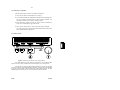
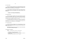
1
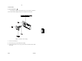
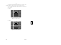
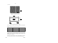
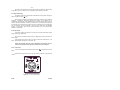
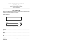
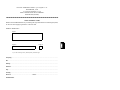
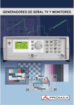
TV SIGNAL GENERATOR
GV-698
1 GENERAL
1.1 Description
The GV-698 TV signal generator is a multi-standard, multi-system unit with
advanced functions. It has been designed using the most modern technology resulting
in great reliability and reduced consumption. Its modular structure makes it highly
versatile and permits rapid access to all its components. Starting from base modules,
it is possible to increase the applications of the instrument by adding modules if
desired.
The GV-698 is particularly suitable for those industrial sectors that require
high-quality pictures such as adjustment and analysis lines, production studios,
technical assistance services, etc. In addition, being easy to operate, it is indispensable
in the training of video technicians.
The GV-698 operates in accord with the CCIR/OIRT recommendations for the
colour systems PAL-SECAM and FCC for the NTSC system and may provide a
modulated signal for practically all the transmission standards presently in use. The
video is equipped with 32 pattern charts to analyze the picture visually or with an
oscilloscope. For geometric adjustments, the electronic circle can be inserted in all the
charts.
To detect defects in the tuning circuits and IF amplifier stages, the GV-698 has
a complete radio-frequency modulator, its principal characteristics being:
-
Frequency range from 37 to 865 MHz
Synthesized frequency output
Tuning by channels or by frequency (in steps of 50 kHz)
Attenuation of output RF signal up to 50 dB (in steps of 10 dB)
The VTR (Video Text Recorder) function is available to check the functioning
of video tape recorders, particularly the functions of "still", stepped image, heads
position, etc.
Microprocessor control, the presentation of information on a wide illuminated
alphanumeric display and the incorporation of a single rotary selector for all the
functions results in simple and easy operation. The functions controlled are:
-
Selection and display of RF by channel or by frequency
Selection of the colour system and sound standard
Selection of the output chart
Storage of up to 32 different programs is possible. Each program
(chart/system-sound standard/frequency or RF channel) may be stored or
retrieved at any time.
Internal (1 kHz/3 kHz) or external modulation of sound is possible. For a
superior analysis of the video and sound signal, there are push–buttons for cancelling
or including certain basic functions, such as:
05/96
GV-698
- 46 -
-
Independent cancellation of the colour subcarrier and of the burst
Inclusion of the electronic circle
Cancellation of the interlace in the video signal
Cancellation of the sound subcarrier
Selection of stereo or dual sound
Independent cancellation of L and R sound
Cancellation of the TELETEXT and VPS signal
Selection of the information to transmit in the VPS signal
On the front panel there is an adjustable composite video output and an RF
output with an attenuator of up to 50 dB. In addition, numerous auxiliary inputs and
outputs increase the possibilities of the instrument considerably. These supplementary
connectors are located on the rear panel:
-
S–VHS output
R, G and B (or G plus synchronisms) outputs
Composite synchronisms output
Synchronisms output for an oscilloscope
L and R sound input
In the Euroconnector:
- Composite video output
- R, G, B (or G plus synchronisms) outputs
- L and R sound inputs and outputs
- Video input (external signal modulation)
The GV-698 has a series of functions which may be optionally included (see
the list of versions and options under item 1.2 of the specifications). The GV–698/11
version includes all these functions.
-
Generator module of the TELETEXT and VPS signals. During recent years,
there has been a growing acceptance of TELETEXT on the part of users,
and the majority of television sets incorporate it. With the GV-698, it is
possible to generate 8 pages in two languages, which can be selected from
the television set (by number or by means of the FLOF or FASTEXT
function), with different combinations of graphics and text in 1.0 and 1.5
levels which permit the verification of all the decoding functions.
The VPS signal (Video Program Service) is an information signal, which is
emitted by television channels during a program, that may activate or stop
the users' video recorders if they are equipped with this feature. This
eliminates the problems caused by changes in the programming to be
recorded.
-
Generator module of the stereo/dual (Zweiton) signal either generates a
second sound carrier to be used as a second mono sound channel, or
provides the right channel stereo information. This signal, like the main
carrier, may be modulated by an external signal.
-
Generator module of the NICAM signal for PAL G and I. The demand for
better quality sound in television systems has resulted in the appearance of
digital coding of sound. This module enables the testing of equipment which
has this feature.
On request by the customer, the logotypes can be custom-programmed to
personalize the source of the image.
05/96
GV-698
- 47 -
1.2 Specifications
The values indicated with tolerances are guaranteed by the manufacturer, those
without are to be nominally expected within a group of identical instruments.
Specifications are valid 10 minutes after switching on.
TV SYSTEM
System
RF Standard
No. of lines/frame
Field frequency
Line frequency
Horizontal synchronism
Line period (1/fH)
Front porch
Synchronism
Blanking
Vertical synchronism
Frame period
Blanking
Duration of impulse of:
Pre-equalization
Equalization
Post-equalization
Scanning of picture
PAL (B,G,H,D,I) colour subcarrier
Frequency
Burst duration
Burst position
Phase
Amplitude error
Phase error
Burst amplitude
Subcarrier amplitude
NTSC (M) colour subcarrier
Frequency
Burst duration
Burst position
Phase
Amplitude error
Phase error
Burst amplitude
Subcarrier amplitude
05/96
PAL/SECAM
B,G,H,D,K,K1,I,L
625
50 Hz
15625 Hz
NTSC
M
525
60 Hz
15734 Hz
64 µs
1.6 µs
4.8 µs
12 µs
63.56 µs
1.59 µs
4.77 µs
11.12 µs
±
±
±
±
100
100
100
100
ns
ns
ns
ns
20 ms ± 100 ns
(H = 64 µs)
25 H + 12 µs
± 100 ns
± 100 ns
± 100 ns
± 100 ns
16.68 ms
± 100 ns
(H = 63.56 µs)
21 H + 11.12 µs
2.5 H
3H
2.5 H
3H
2.5 H
3H
Selectable: Interlaced ratio 2:1
Not interlaced
4.43361875 MHz <± 30 ppm (10ºC to 40ºC)
2.4 µs (10 ± 1 period of Fsc)
5.6 µs ± 100 ns from the line previous
synchronism flank.
± 135º referred to the U axis with the sequence
Line
Frame
Even
Odd
1 2 3 4
- - + +
+ + - -
±5%
±3%
ON/OFF, selectable
ON/OFF, selectable
3.579545 MHz <± 30 ppm (10ºC to 40ºC)
2.38 µs (10 ± 1 period of Fsc)
5.56 µs ± 100 ns from the line previous
synchronism flank.
- 180º referred to the U axis
±5%
±3%
ON/OFF, selectable
ON/OFF, selectable
GV-698
- 48 SECAM (B,G,H,D,K,K1,L) colour subcarrier (Version /3,/5,/11)
For = 4.406250 MHz ± 2 kHz
Subcarrier frequency
Fob = 4.250000 MHz ± 2 kHz
(sinc. fH)
Identification pulses
Line 7 to 15 in odd fields
Frame (position)
Line 320 to 328 in even fields
Dr = 4.756250 MHz ± 35 kHz
Frequency
Db = 3.900000 MHz ± 35 kHz
Selectable ON/OFF with interlace button
Frame
Selectable ON/OFF with burst button
Line
Chrominance signal
D'r = -1.9 (E'r - E'y)
Amplitude
D'b = 1.5 (E'b - E'y)
Bell filter
Precorrection of chrominance
Central frequency
4.286 MHz ± 0.020 MHz
of Bell filter
DISPLAY
Digital, 16 characters, with chart, TV
standard/sound system, channel and
frequency (5 digits) indications. Program
indicated in the Store/Recall mode.
RADIO–FREQUENCY OUTPUT
Range covered
Tuning
Store/recall
Frequency indicator
Output amplitude
Attenuation
Impedance
Connector
37 to 865 MHz (synthesized)
By frequency: in steps of 50 kHz
By channels: CCIR (FCC Version /1,/6,/8)
32 programs
5 digits
90 dBµV ± 3 dB
50 dB (in steps of 10 dB)
75 Ω
BNC
VIDEO MODULATION
Modulation type
Modulation index
AM, double side band
85% (internal modulation)
VIDEO OUTPUT
Impedance
Amplitude
Nominal value
Polarity
Coupling
Blanking cont.lev.
Connector
75 Ω
Variable from 0 to 1.2 V
1V
Positive
Direct coupling
0 V (nominal)
BNC or Euroconnector
Y–C (S–VHS) OUTPUT COMPONENTS
75 Ω
Impedance
0.7 V (max. white level luminance)
Amplitude
0.3 V (colour burst)
S–VHS
Connector
05/96
GV-698
- 49 -
R–G–B OUTPUTS
Impedance
Amplitude
G synchronisms
Connector
75 Ω
0.7 Vpp
0.3 Vpp (selectable ON/OFF)
BNC or Euroconnector
SYNCHRONISMS OUTPUT
Impedance
Amplitude
Polarity
Connector
75 Ω
2.0 Vpp
Positive or negative (selectable)
BNC
OSCILLOSCOPE TRIGGER OUTPUT
75 Ω
Impedance
2.0 Vpp vertical, 1.5 Vpp horizontal
Amplitude
BNC
Connector
SOUND OUTPUT
Impedance
Amplitude
Connector
1 kΩ
0.4 Vpp
Euroconnector
VIDEO INPUT
Impedance
Coupling
Connector
10 kΩ
Direct coupling
Euroconnector
EXTERNAL L.F. SOUND INPUT
Impedance
Amplitude
Bandwidth
Connector
100 kΩ
Max. 0.5 Vpp
100 Hz to 15 kHz
DIN 41524 or Euroconnector
SOUND MODULATION (MULTISTANDARD–MONO)
Carrier
ON/OFF selectable
(sinc. fH)
4.5 MHz
(M)
Frequency
5.5 MHz
(B,G,H)
6.0 MHz
(I)
6.5 MHz
(D,K,K1,L)
Video/sound
13 dB
carrier ratio
Int. FM (1 kHz) (M,B,G,H,D,K,K1,I)
Type of modulation
Ext. FM
(selectable)
AM
(L)
FM modulation
50 µs
(B,G,H,D,K,K1,I)
Pre-emphasis
75 µs
(M)
30 kHz
(in FM)
Modulation deviation
50 %
(in AM)
Modulation index
MODULATION OF STEREO/DUAL SOUND (ZWEITON) (OPTIONAL, OPT-698-2)
ON/OFF selectable
Carrier
Carrier 1
Carrier 2
Sinc. fH
5.5 MHz
5.7421875 MHz
Frequency
05/96
GV-698
- 50 Video/sound
carrier ratio
Type of modulation
(selectable)
Pre-emphasis
Modulation deviation
Mode
Dual
Stereo
Detection mode
Pilot frequency
Modulation
Modulation index
Identif. frequency
13 dB
Int. FM (1 kHz)
Ext. FM
Max. 0.5 Vpp
50 µs
30 kHz
20 dB
int. FM (3 kHz)
Ext. FM
Max. 0.5 Vpp
50 µs
30 kHz
L
(L+R)/2
R
R
54.6875 kHz
(3.5*fH)
AM
50 %
274.1 Hz (fH/57) dual
117.5 Hz (fH/133) stereo
MODULATION OF NICAM SOUND (OPTIONAL, OPT-698-4)
ON/OFF selectable
Carrier
5.850 MHz
<± 30 ppm
PAL B,G, L
6.552 MHz
<± 30 ppm
PAL I
Carrier ratio
20 dB (B,G,I), 26 dB (L)
video/sound
4QPSK
Modulation
Mono, dual, stereo
Modes
Internal sources
1 kHz, ON/OFF selectable
Channel 1
3 kHz, ON/OFF selectable
Channel 2
ON
Sound reserve flag
32 samples/block
Signal coding
16 blocks.
728 kbits/s
Transmission speed
In accord with CCITT Rec. J17
Pre-emphasis
40% roll-off cosine (PAL B,G,)
Spectrum form
100% roll-off cosine (PAL I)
TELETEXT GENERATOR (LEVEL 1.0 & 1.5) AND VPS (OPTIONAL, OPT-698-3)
ON/OFF selectable
Teletext
(sinc. fH)
6.9375 MHz (444*fH)
Frequency
NRZ (no return to zero)
Transmission mode
From 11 to 15 and 19 to 22 in odd fields
Data lines
From 324 to 329 and 332 to 335 in even fields
8 different pages (two languages sent
Content
consecutively).
ON/OFF selectable
VPS
5.0 MHz
Frequency
Biphase
Transmission mode
16 odd field
Data line
Selectable through change of chart apart from
Content
the functions stop, start and standby which are
selected through the keyboard.
Black level
"0" Level
66% ± 5% of the white level
"1" Level
Signal output together with the composite
Connector
video by BNC and Euroconnector.
05/96
GV-698
- 51 LOGOTYPE GENERATOR
Window position
Charts A1 and A4 (logotypes)
Charts A3 and C1 (VTR)
VIDEO TEST RECORDER (VTR)
VTR format
Velocity
8-position mobile rectangle
1 position per image field
POWER SUPPLY
Mains voltage
Power consumption
AC 110-125-220-230-240 V ± 10% 50-60 Hz
20 W
OPERATING ENVIRONMENTAL CONDITIONS
Up to 2000 m
Altitude
From 5 to 40 ºC
Temperature range
80% (up to 31 ºC), decreasing lineally up to
Maximum relative humidity
50% at 40 ºC.
MECHANICAL FEATURES
Dimensions
Weight
W.288 x H.102 x D.247 mm
3 kg
ACCESSORIES INCLUDED
90901207
BNC/TV coaxial cable CC-07
90901105
Mains cable CA-05
0 FS0060
1A F 250 V spare fuse
VERSIONS
90206980
90206981
90206982
90206983
90206985
90206986
90206988
90206989
05/96
GV-698
GV-698/1
GV-698/2
GV-698/3
GV-698/5
GV-698/6
GV-698/8
GV-698/11
NTSC/PAL CCIR channels
NTSC/PAL FCC channels
NTSC/PAL OIRT channels
SECAM/NTSC/PAL CCIR channels
SECAM/NTSC/PAL OIRT channels
NTSC/PAL N FCC channels
NTSC/PAL M FCC channels
Complete SECAM/NTSC/PAL. Includes options
-2 ZWEITON, -3 TELETEXT & VPS, -4 NICAM.
GV-698
- 52 -
OPTIONS
90296981
90296982
90296983
90296984
OPT-698-1
OPT-698-2
OPT-698-3
OPT-698-4
Special logotype programming
ZWEITON sound
TELETEXT, VPS
NICAM sound
NOTE: According to I.E. PROMAX's information the NICAM sound transmission system
has by now been adopted by the following countries:
NICAM B/G
NICAM I
NICAM L
Spain
Portugal
Sweden
Norway
Denmark
Iceland
Finland
Singapore
New Zealand
United Kingdom
South Africa
Ireland
Hong Kong
France
05/96
GV-698
- 53 -
2 SAFETY RULES
*
Use this equipment connected only to devices or systems with their common at
ground potential.
*
This is a class I equipment, for safety reasons plug it to a supply line with the
corresponding ground terminal.
*
This equipment can be used in CATEGORY II installations and Pollution Degree
1 environments.
*
When using some of the following accessories use only the specified ones to
ensure safety.
Power cord
*
Observe all specified ratings both of supply and measurement
*
Remember that voltages higher than 60V DC or 30V AC rms are dangerous
*
Use this instrument under the specified environmental conditions
*
The user is only authorized to carry out the following maintenance operations:
To replace the mains fuse of the specified type and value
To replace the logo EPROM
On the Maintenance paragraph the proper instructions are given. Any other
change on the equipment should ve carried out by qualified personnel.
*
The Measure negative is at ground potential
*
Do not obstruct the ventilation system
*
Follow the cleaning instructions described in the Maintenance paragraph
05/96
GV-698
- 54 -
*
Symbols related with safety:
DIRECT CURRENT
ALTERNATING CURRENT
DIRECT AND ALTERNATING
GROUND TERMINAL
PROTECTIVE CONDUCTOR
FRAME TERMINAL
EQUIPOTENTIALLITY
ON (Supply)
OFF (Supply)
DOUBLE INSULATION PROTECTED
(Class II Protection)
CAUTION
(Risk of electric shock)
CAUTION REFER TO ACOMPANYING DOCUMENTS
FUSE
05/96
GV-698
- 55 -
3 INSTALLATION
3.1 Power requirements
This equipment requires a mains power source of 110-125-220 or 230/240 V
AC 50 to 60 Hz. Mains operating voltage can be selected at the rear panel.
Figure 1.- Selection of mains voltage.
1.- Pull out the fuseholder lid.
2.- Set the proper fuse for the desired mains voltage.
3.- Insert the fuseholder lid so the [ A ] pointer faces the desired mains voltage
display [ B ].
05/96
GV-698
- 56 -
CAUTION:
THE EQUIPMENT IS FACTORY SET FOR 220 V OPERATING VOLTAGE.
BEFORE SWITCHING ON THIS INSTRUMENT, SET THE VOLTAGE
SELECTOR TO THE PROPER POSITION AND BE SURE THAT THE FUSE
VALUE IS ACCORDING TO THE MAINS VOLTAGE.
FUSE TYPE SHOULD BE: 5 x 20 mm., 250 V.
0.5 A F
1AF
FOR 220, 230 and 240 V
FOR 110 and 125 V
AVOIDING THIS DIRECTIONS COULD DAMAGE THE EQUIPMENT
3.2 Grounding
In order to guarantee safe operation of the GV-698, a suitable connector is
provided on the rear panel for connection to GROUND (Mains Connector [35]).
ATTENTION
Any equipment manufactured with a power supply connected to the chassis
and which is to be connected to the GV-698 must be supplied with an
adequate isolating transformer. Non-observance of this norm may cause
damage to the instrument and/or produce damage to the operator.
3.3 Installation and start-up
The equipment is prepared for use as desk–top equipment.
After having selected the power supply voltage, the equipment may be
connected to the mains and switched on by activating the mains switch [1].
The equipment's highest level of performance is obtained at about 10 minutes
after switching on. This period stabilizes the components sensitive to the thermal
gradient.
ATTENTION
For correct operation of the GV-698, ensure, when connecting the equipment
to an external instrument, that the impedances are correctly matched (see item
1.2 of specifications), otherwise incorrect operation may result.
E.g.: in the case of connection to a TV with a balanced R.F. input of 300 Ω
impedance, an impedance adaptor model A-75/300 GV or similar should be
used.
05/96
GV-698
- 57 4 OPERATING INSTRUCTIONS
4.1 Control description
Figure 2.- Front panel.
[1]
[2]
[3]
[4]
[5]
[6]
[7]
[8]
[9]
[10]
[11]
[12]
[13]
[14]
[15]
[16]
[17]
[18]
[19]
[20]
[21]
[22]
[23]
[24]
05/96
LINE . Mains switch
Row indicator
Column indicator
STO, RCL. Memory selector (recall/store)
SEL. Rotary function selector (chart/system–standard/channel–frequency)
Alphanumeric display
TUNE SELECT . Rotary selector
10. 10 dB attenuator
20. 20 dB attenuator
20. 20 dB attenuator
. RF output
RF
START . VPS signal information (start/stop) selection button
PRG . VPS signal information (program/standby) selection button
TXT/VPS OFF . Teletext and VPS signal suppression button
R OFF . R channel suppression button (stereo sound/dual)
L OFF . L channel suppression button
DUAL. Stereo or dual sound mode selection button
OFF . Sound carrier suppression button
IL. OFF . Interlace suppression button
CIRC . Circle addition button
OFF . Colour suppression button
BURST OFF . Burst suppression button
LEVEL. Video output level control
. Video output connector
VIDEO
GV-698
- 58 -
Figure 3.- Rear panel.
[30]
[31]
[32]
[33]
[34]
[35]
[36]
[37]
[38]
[39]
[40]
[41]
. Synchronisms output
SYNC
. Composite signal output for oscilloscope trigger
TRIG. SCOPE
. R signal output
R
. G signal output
G
. B signal output
B
Mains input
EURO-AV . Euroconnector connector
SYNC. G. G synchronisms ON/OFF selector
. S–VHS output
POLARITY . Synchronisms output polarity selector
. External LF input connector
LF MODULATION
SOUND . Internal/external LF selector
4.2 Using the GV-698
This section explains how to use the GV–698 including the operation of the
keyboard, the composite video signal, the radio-frequency output and a detailed
description of the information appearing on the display.
05/96
GV-698
- 59 4.2.1 Selection of TV standard
Figure 4.– Selection of TV standard and memory.
To select the desired TV standard follow the instructions below:
1) Press simultaneously the STO and RCL buttons corresponding to the group
[4]. The data presentation on the alphanumeric display will change: on the
left side the abbreviated denomination will appear, and on the right a
complete description of the equipment system at that moment.
2) Select the desired system by means of the TUNE SELECT rotary selector
[7]. The options available are shown on table 1.
3) By pressing the SEL button of the group [5] the process will be completed.
The alphanumeric display will return to its normal mode and the
abbreviation of the system selected will appear in the position corresponding
to indication of the system.
05/96
GV-698
- 60 -
ABBREVIAT.
DENOMIN.
COMPLETE
DENOMINATION
CARRIERS SEPARATION
SOUND 1
SOUND 2
Pb
PAL B/G/H
5.5 MHz
-
Pi
PAL I
6.0 MHz
-
Pd
PAL D/K
6.5 MHz
-
Pz
PAL ZWEITON
5.5 MHz
5.742 MHz
P#
PAL I-NICAM
6.0 MHz
6.552 MHz
P*
PAL G-NICAM
5.5 MHz
5.850 MHz
Sb
SECAM B/G/H
5.5 MHz
-
Sd
SECAM D/K/K1
6.5 MHz
-
Sl
SECAM L
6.5 MHz (AM)
-
Nm
NTSC M
4.5 MHz
-
EX
VIDEO EURO-AV
-
-
Table 1
4.2.2 Storing a configuration
To store a configuration follow the instructions below:
1) Select all (chart/system–standard/channel–frequency) that which you wish
to store (see items 4.2.1, 4.2.5, 4.2.6 and 4.2.7).
2) Press the STO button corresponding to the group [4]. The LED situated
below the MEM position will light and the message "STO XX" on the display
will indicate that this option has been selected, "XX" indicating the number
of the memory currently selected.
3) Select the memory position in which you wish to store the information by
means of the TUNE SELECT [7] rotary selector.
4) Press the STO button again, by which the process will be completed.
05/96
GV-698
- 61 -
4.2.3 Retrieving a configuration
Take the following steps to retrieve the desired configuration:
1) Press the RCL button corresponding to the group [4]
2) The LED situated below the MEM position will light and the message "RCL
XX" on the display will indicate that this option has been selected, "XX"
indicating the number of the memory currently selected.
3) Select the memory position in which you wish to store the information by
means of the TUNE SELECT [7] rotary selector.
4) Press the RCL button again, by which the process will be completed.
The entire configuration stored (chart/system-standard/channel-frequency)
will be updated within the equipment.
4.2.4 Rotary selector
Figure 5.- Selection of the function of the rotary selector.
The TUNE SELECT [7] rotary selector incorporated in the GV-698 enables
selection of chart, system, standard, channel and frequency to be simply made.
The SEL button in the group [5] permits the selection of the function indicated
by the rotary selector. By pressing this button repeatedly, the information corresponding
to the type of chart, system, channel and frequency is successively selected. The LED
situated below each function is lit in order to indicate the selected function.
05/96
GV-698
- 62 -
4.2.5 Chart selection
Keep the SEL button corresponding to the group [5] pressed until the LED
situated below the PAT indication is lit. The chart selected will be displayed in this
position. Then turn the TUNE SELECT rotary selector [7] to move successively through
the 32 charts that can be presented by the video generator.
A column in letters (see column indicator [3]) and a row in numbers (see row
indicator [2]) will appear on the visual display. In order to enable pictures to be more
easily selected, these have been arranged into 8 columns (all related in their
performance).
-
Groups A to E for colour and general adjustments
Groups F to H for the adjustment of B/W parameters
4.2.6 Channel selection
Keep the SEL button corresponding to the group [5] pressed until the LED
situated below the CHANNEL indicator is lit. The selected channel will be displayed.
Then turn the TUNE SELECT rotary selector [7] and the channels stored in the
microprocessor will be consecutively selected. The channels appear arranged
according to frequency (standard TV and cable TV channels).
The television channels are indicated by "C" and a number. For instance, TV
channel 41 would be indicated as "C41". The cable TV channels, on the other hand,
are specified by an "S", for example "S11". The channels implemented depend on the
selected version (see list of versions in item 1.2 Specifications).
4.2.7 Frequency selection
Keep the SEL button corresponding to the group [5] pressed until the LED
situated below the FREQ. MHz. indicator is lit. The selected frequency will be
displayed. Then turn the TUNE SELECT rotary selector [7] and the frequency will
change in steps of 50 kHz.
NOTE: When the frequency does not correspond to a channel, the information
on the alphanumeric display will disappear.
4.2.8 Application of test pictures
Group A.-
-
05/96
General analysis of the picture, combined pictures.
A1 Monoscope 1 with possibility of insertion of logotypes
A2 Colour bars / Blue with zero luminance
A3 Monoscope 2 / VTR (Video Test Recorder) signal to analyze the
operation of videos.
A4 Monoscope 3 with possibility of insertion of logotypes
GV-698
- 63 -
Group B.-
-
-
B1 Colour bars
B2 Horizontal colour bars
B3 Luminance/Colour bars/Multiburst/DEM
Composite chart for contrast control, tint control, definition and colour
demodulators.
B4 Colour bars / Scale of greys
Saturation in optimal conditions for the adjustment of contrast and
brightness.
Group C.-
-
C1
C2
C3
C4
D1
D2
D3
D4
-
-
05/96
Colour demodulator control, phase and delay line.
E1 Antipal with split–field 50% luminance
Adjustment of phase, delay line and colour demodulators.
E2 Axes and antipal
Adjustment of colour demodulators.
E3 Colour bars / Multiburst
Verification of the video amplifier bandwidth.
E4 Delay
Chrominance and luminance delay check.
Group F.-
-
Purity, noise and beam current control for R, G and B. R, G, B
outputs check.
Red raster
Green raster
Blue raster
RGB
Group E.-
-
Colour luminance control, R, G, B amplitude, seen on the screen.
White split 100% / VTR signal colour bars
Red split colour bars
Green split colour bars
Blue split colour bars
Group D.-
-
Colour saturation control, tint control, etc.
Resolution, video response and linearity control.
F1 Scale of greys
Video amplifier linearity (correct ratio between the values of the electronic
beam currents), whiteness control and adjustment, contrast and brightness
control.
F2 Multiburst
Determination of the bandwidth of the video amplifier.
F3 Chequer-board
Video amplifier low frequency response.
F4 Window
Response to transients in the video signal, DC restoration circuit check
(clamping), and delay.
GV-698
- 64 -
Group G.-
-
-
-
Focus control, geometry and matt supply.
G1 100% white
Verification of the limiter circuit for the beam current, modulation adjustment
on videotapes, measurements of the signal/noise ratio.
G2 black
Clamping check, measurements of the signal/noise ratio, adjustment of the
level of black.
G3 50 Hz rectangular
Clamping circuits check.
G4 MAT
Very High Tension source control.
Group H.
-
H1 Cross and rectangle
Aspect, geometry and centrality ratio.
H2 Framed grid
Centered adjustment of the picture and overscanning.
H3 Grill
Static and dynamic convergence adjustment, interline check.
H4 Points
Picture suitable for the adjustment of the focus voltage.
4.3 Function buttons which modify the composite video signal
Their effect may be observed at the outputs at which a composite video signal
is present (VIDEO output [24], EURO–AV Euroconnector [36] pin 19 and Y–C
output [38], and in the RF modulated signal (RF connector [11]).
-
BURST OFF [22]: press this button to suppress the burst of the composite
video signal and enable the correct operation of the colour killer in the
receivers to be checked. In a correctly adjusted TV receiver no colour
appears on the screen if the burst is cancelled. Anomalous colorations may
be due to high gain in the amplifiers and some deficiency is likely to have
appeared at this stage.
When the SECAM system is selected, pressing this button eliminates the
line identification signal.
-
OFF [21] (Chrominance): press this button to disable the chrominance.
It enables suppression of the colour subcarrier in the video signal in order
to analyze the luminance of the colour charts.
-
CIRC. [20] (Electronic circle): press this button to activate the circle which
may be inserted in any chart and is particularly useful in geometric
adjustments.
NOTE: the insertion of the circle in the multiburst chart is not perfect, since
this signal does not pass through circuits which would limit its bandwidth. As
the circle in this chart does not provide any information of interest, it is
preferable not to insert it during definition studies.
05/96
GV-698
- 65 -
-
IL. OFF [19] (Interlace): press this button to suppress the interlace and
enable an easier check to be made of the vertical integration system of the
synchronisms separator. In convergence adjustments a non-interlaced signal
seems more suitable in order to avoid flicker.
NOTE: When the SECAM system is selected, pressing this button permits
the inclusion of the picture identification signal.
4.4 Function buttons which modify the sound modulation
The selection of the sound source is carried out by means of the SOUND
switch [41].
The internal modulating signal is 1 kHz (L channel) and 3 kHz (R channel); if
the input of an external sound signal is desired, use the LF MODULATION
[40]
input on the rear panel.
-
OFF [18]: press this button to suppress the sound carrier on the RF
output.
-
DUAL [17]: press this button to select the dual mode. If the button is not
pressed, stereo mode is selected (in PAL ZWEITON and NICAM).
-
L OFF [16]: press this button to suppress the signal which modulates the
main carrier (in all systems) or the selection of the digital information
corresponding to the L channel (in NICAM).
-
R OFF [15]: press this button to suppress the signal which modulates the
second carrier (in PAL ZWEITON) or the selection of the digital information
corresponding to the R channel (in NICAM).
4.5 Function buttons which operate on the Teletext and VPS signals
Only for equipment with teletext signal decoders, levels 1 and 1.5.
-
TXT/VPS OFF [14]: press the button to cancel the teletext and VPS
information in the composite video signal.
Only for equipment with VPS signal treatment. The information transmitted by
this signal during recording corresponds to the day, month, hour and minute when the
recording of the desired broadcast is to start. It also transmits the information on the
country and broadcaster of the program. The minute of the starting time of recording
may be modified by changing the chart selection.
-
TXT/VPS PRG. [13]: when this button is pressed, the information to be
transmitted through the VPS signal sets the video to pause.
-
TXT/VPS START [12]: when this button is pressed, the information to be
transmitted through the VPS signal sets the video to stop recording.
NOTE: when both buttons are pressed, a code of state is transmitted.
05/96
GV-698
- 66 -
The information transmitted on each chart is specified below:
Information common to all charts:
Day:
Month:
Time:
Country:
01
01
01
Germany
Information that varies in each row of charts:
Row 1
Row 2
Row 3
Row 4
01
05
10
15
Minute
Table 2.
Information that varies in each column of charts:
Program
origin
Stereo/Mono
Fit/Not fit
Col. A
Col. B
Col. C
Col. D
Col. E
Col. F
Col. G
Col. H
ARD
Bundesweit
ZDF
Bundesweit
3rd PROG.
Hessen 3
Landesweit
ARD/ZDF
gem Vorm P
ARD SAT
1 Plus
ZDF SAT
3 Sat
BRI
Regional
HRI
Regional
Stereo
Mono
Dual
Stereo
Stereo
Mono
Dual
Stereo
Fit
Fit
Fit
Not fit
Fit
Fit
Fit
Not fit
Table 3.
4.6 Logotype generator
Although the GV-698 is provided with a pre-programmed standard logotype, it
is possible to request additional logotypes made according to the customer's
specifications (OPT 698-1 option). The use of a special logotype is of particular interest
when it is desired to personalize the source of the picture. It may be very useful in
video studios, cable TV networks, communal video installations, broadcasting stations,
etc. In addition, it may be used as advertising publicity for any business supplied with
a receiver.
Generation of the logotype is based on the reading of the EPROM memory
programmed by the manufacturer. If this integrated circuit is exchanged for another
with a different logotype, the new text and/or drawing will appear in the window.
If the customer applies for a logotype, he will be sent the text or logotype
requested recorded on a memory.
4.6.1 Application possibilities
IF YOU ARE GOING TO APPLY FOR A LOGO, PLEASE READ CAREFULLY THIS
SECTION, INDISPENSABLY.
05/96
GV-698
- 67 -
Logo recording is achieved by digitalizing a sample through a computer. At any
rate, when applying for a logo, some questions should be taken into account.
-
Logos are located in fixed positions in the charts, Sizes and dimensions are
described hereafter.
a) Chart A1
Figure 6.- Logo position in chart A1.
b) Chart A4
Figure 7.- Logo position in chart A4.
05/96
GV-698
- 68 -
c) Chart B4
Figure 8.- Logo position in chart B4.
Figure 9.- Logo position inside the window.
-
Only text generation and black-and-white logos availability has been designed.
-
Definition achievable from picture held in the screen is:
Wide
High
Logo 1
416 points
64 lines
Logo 2
312 points
32 lines
Logo 3
52 points
32 lines
Table 4.
-
Digitalizer's task will be reduced remarkably if contrast of that logo to be
scanned is good. Therefore, the order template should be filled up in thick
black (Indian ink o felt-tip pen).
-
Wording may be added whether to a logo or ordered separately. In the latter
case, the logo generator will work as a conventional character generator.
05/96
GV-698
- 69 -
-
Limitations in the number of characters depends on character size. Unless
otherwise directed by the customer in his order application, wording will be
recorded in accordance with an aesthetic rule (using the greatest size allowed,
horizontal and vertical centering inside a window).
-
Because of the scarce variety of letters available by the character generator,
it would be preferable to send us a template with that wording to be included,
if more definition letters are wanted. In this way, more quality will be achieved,
above all in large size letters (see type 1).
Two application cards are available, attached to the last page of the manual.
If required, further cards may be requested to I. E. PROMAX S.A.
To order a logo, just fill up one of the two templates printed on the "Order
Card". Dimensions are scale of those actual ones displayed in the TV set screen.
IMPORTANT NOTICE
If you want to generate a logo, it is advisable to attach an original anagram. Your
anagram may be picked out from any business card or document; it gives a very
useful additional information in digitalizing the requested logo properly.
Figure 10.- Logo example.
In the event diverse logos would be required for different applications, a "logo
library" could be created if necessary, including exchangeable EPROMS for every
particular case.
Distributors and manufacturer are responsible for EPROM recording and
procedures. Please refer to them for applicable tariffs or whatever matter.
4.6.2 Replacing the EPROM memory
On receiving the EPROM with the recorded text or logo, replace the current
EPROM by the one received. This step is to be performed with the unit turned off.
Special care should be given to following points of this process:
05/96
-
Open the GV-698 by releasing the 4 locking screws inside the support legs.
-
Draw out the board fastening bar by releasing the 2 screws at the top bar.
-
Pull out the logo generation card (2nd card from the left).
GV-698
- 70 -
Figure 11.- Logo board location.
-
Replace the current EPROM by the one included in the personalized logo.
Figure 12.- EPROM position.
-
Be sure the IC notch agrees with the one drawn in the silkscreen print of the
PC board.
-
Carefully insert pins properly in the socket.
-
In connecting the logo generating card again, special care is to be given in
matching all board pins with card connectors (VERY IMPORTANT).
-
Set the board fastening bar again.
-
Lock the unit.
WARNING: PROMAX S.A. is not responsible for damages, whether in the logo
generator or the GV-698, occurred because of a wrong memory inserting in its
socket.
05/96
GV-698
- 71 -
4.6.3 Letter type
The letter types available are the fonts of general use in Windows (i.e. Arial,
Courier, Times New Roman, etc.).
05/96
GV-698
- 72 -
05/96
GV-698
- 73 5 DESCRIPTION OF INPUTS AND OUTPUTS
5.1 Composite video output (BNC)
The composite video output is achieved through the VIDEO connector
[24]
on the front panel. The polarity of the signal is positive and the synchronisms negative,
the black level being 0 V. The amplitude may be varied by means of the video level
control LEVEL [23] between 0 and 1.2 Vpp. In the "CAL" position, the amplitude is
normalized at 1 Vpp. This signal is very useful in testing B/W and colour video
monitors, linear amplifiers, VCR or any other equipment which operates with a
composite video signal.
CAUTION
This signal must not be connected to any live point in a circuit, but only to
normalized video inputs of 75 Ω impedance. Any damage produced in the
equipment due to non-observation of this precaution is not covered by the
guarantee.
5.2 Modulated RF output
The modulated RF output (with the video and sound selected) is achieved
through the RF connector
[11] on the front panel.
The modulation of the RF carrier by the video signal is achieved by means of
a suitably polarized diode modulator (this achieves double sideband modulation); the
inversion of modulation, positive or negative, is achieved by modifying the polarity of
this video signal. Given that a broadcasting station uses vestigial-sideband
transmission, the correct tuning-frequency corresponds:
-
If it is tuned to the TV -> to higher frequency
If it is tuned to the generator -> to lower frequency.
Incorrect tuning can be clearly distinguished from correct tuning by the
appearance of a low signal/noise ratio, inversions of modulation or lack of synchronism.
The wide frequency margin of the GV-698 permits the selection of 38.9 MHz
(45,75 in USA), which is the intermediate frequency used by TV receivers. It is possible
to connect the modulated signal to the IF stage input and test, in case of failure,
whether it occurs in the tuner or in a later stage.
The possibility of attenuating the RF output has been foreseen for testing the
automatic gain control circuits and the sensitivity of television sets: one three-stage
attenuator, two -20 dB (buttons [9] and [10]) and one -10 dB (button [8]) are
incorporated, permitting a total maximum attenuation of -50 dB (30 µV) in steps of
-10 dB. Normally, a correctly adjusted television set shows an effect of snow in an
image when 30 dB (300 µV) attenuation is selected.
5.3 Synchronisms output
The synchronisms output is situated on the rear panel, through the SYNC.
connector
[30]. It serves for the synchronization of monitors with an input for
separate synchronisms, the horizontal and vertical synchronisms are present.
05/96
GV-698
- 74 -
By means of the POLARITY selector [39] its polarity (positive or negative) may
be inverted in order to adapt it to the requirements of the monitor examined.
5.4 Trigger oscilloscope
The trigger output for the oscilloscope is situated on the rear panel, through the
TRIG. SCOPE connector
[31].
At this output horizontal synchronisms are mixed with vertical ones of a different
amplitude. It enables a perfectly synchronized TV picture to be obtained on an
oscilloscope, independently of the amplitudes of the observed signals and thus can be
used to analyze the different circuits of a television set. This output should therefore
be connected to the external synchronism input of the oscilloscope. If the oscilloscope
has an automatic TV filter connected to the time base switch (like all PROMAX
models), it is possible to pass from the horizontal frequency to the vertical without
losing the synchronism.
5.5 R-G-B outputs
The R-G-B outputs are situated on the rear panel, through three BNC sockets
[32], [33] and [34], respectively.
By means of the selector SYNC.G [37] it is possible to insert synchronisms in
the G output.
These signals serve for the testing of colour monitors with analogous R, G, B
inputs, special effects equipment, mixer desks, etc.
NOTE: these outputs cannot be used in "ANTI-PAL" chart analysis, since it is
a natural characteristic of this signal that it affects the colour subcarrier.
5.6 LF sound input
This is via the DIN41524 LF MODULATION socket
[40] situated on the rear
panel.
External audio signal inputs which may be used to modulate TV signal sound
carriers.
Figure 13.- LF sound input socket.
05/96
GV-698
- 75 -
[1]
[2]
[3]
[4]
[5]
Left channel audio output (not connected)
Audio ground
Left channel audio input
Right channel audio output (not connected)
Right channel audio input
5.7 S-VHS output
This is via the 4-contact socket
[38] on the rear panel.
Separate luminance and chrominance outputs used in the S-VHS system are
available. Their use as a high quality video standard is becoming more and more
widespread and the quantity of television sets and video equipment incorporating them
is increasing.
Figure 14.- S-VHS socket.
[1]
[2]
[3]
[4]
Luminance signal ground
Chrominance signal ground
Luminance signal
Chrominance signal
05/96
GV-698
- 76 -
5.8 Euroconnector (DIN EN 50049)
Figure 15.- Euroconnector.
Also known as SCART or PERITEL connector (according to the NF-C92250
norm). The output signals in this socket as follows:
No. OF PIN
1
2
3
4
5
6
7
8
9
10
11
12
13
14
15
16
17
18
19
20
21
05/96
SIGNAL
Right channel audio output
Right channel audio input
Left channel audio output
Audio ground
Blue ground (B)
Left channel audio input
Blue output (B)
Switching voltage
Green ground (G)
Interface bus digital
Green output (G)
Interface bus digital
Red ground (R)
Reserved bus digital
Red output (R)
Blanking signal
Composite video ground
Blanking return
Composite video output
Video input
Connector shell ground
CHARACTERISTICS
(not connected)
(not connected)
(not connected)
(not connected)
(not connected)
(not connected)
GV-698
- 77 -
6 PRINCIPLES OF OPERATION
6.1 Circuit description
This section deals with a general explanation of the operation of the GV-698.
The items below refer to the block diagram and to the diagrams of the equipment.
a) µC control
Controls the presentation of the display according to the user's selections
(chart, channel and frequency). It is responsible for the transmission of data to
the synthesized RF unit and for the storage, in a E2PROM memory, of various
configurations selected by the user (up to 32 memories). In the internal
EPROM, besides the control program, the tables corresponding to TV channels
(standard CCIR or FCC) are stored.
b) Display
It is responsible for the alphanumeric presentation of the data transmitted by
the µC (it can present 1 row of 16 characters). In addition, it provides
illumination to enable the data to be more easily seen.
c) Function buttons
There are 11 buttons situated on the lower front part. They serve to activate
and disactivate the basic functions, divided into three groups: video, sound and
teletext/VPS.
d) Synchronisms and logic control generator
The module which generates the basic signals of the video generator.
In accord with the selection signals of the system transmitted by the µC is
responsible for the generation of all the synchronisms signals, the colour carrier
and auxiliary signals employed by other modules of the equipment.
A PLL circuit is responsible for the generation of a 20 MHz signal providing the
maximum resolution per line.
In accord with the chart selection signals transmitted by the µC and internal
signals, the different addresses of an EPROM, which contains the information
on the data to be transmitted to the video output, are sampled.
e) Multiburst and electronic circle generator
The multiburst generator is based on charge and discharge of a capacitor by
means of a constant current source. The switching between the charge and
discharge is carried out in the comparator circuit and the selection of various
frequencies by means of the intensity variation of the current source. After this,
the triangular signal generated is shaped by means of diodes to make it almost
sinusoidal.
The electronic circle generator is based on scanning the data contained in an
EPROM (at 20 MHz) synchronized with the periods of the picture and line and
switching depending on the standard selected.
In addition, this module contains the R, G and B signal output stages.
f) PAL/NTSC/SECAM colour modulator
This is composed of a common part, which generates signals (R-Y) and (B-Y)
or Dr and Db, depending on the system selected:
05/96
GV-698
- 78 -
-
PAL/NTSC modulator: the sum of the signal generated by two AM
modulators.
-
SECAM modulator: FM modulation of the Dr and Db signals synchronized
with the line frequency.
The chrominance signal obtained is added to the luminance (delayed in
SECAM). The composite video signal will be inverted or not, depending on the
system selected, to be transmitted to the RF modulator input.
g) Logotype generator
Based on the scanning of the data contained in an EPROM (at 20 MHz),
synchronized with the line and frame frequencies, it is also provided with
auxiliary signals indicating position and contents of the logo. The VTR signal
is also generated in this module.
h) Teletext and VPS generator
Based on the scanning of the data contained in an EPROM (at 5 MHz/VPS and
6.9375 MHz/teletext synchronized with the line frequency). This module is
responsible for the generation of the signals which control this board (frequency
switching, appearance of signals in the video signal, etc.).
i) L sound carrier generator
This module is divided into differentiated parts:
-
Internal LF signal generator (Wien bridge oscillator), LF input stage
(pre-emphasis filters of 50 µs and 75 µs), and LF signal switching.
-
Sound carrier generator and FM modulator synchronized with the line
frequency, programmable counter depending on the standard selected,
summator of the LF signal for the modulation of FM.
-
AM modulator (Secam/L)
The circuit is responsible for the multiplexing of the signal in order to obtain
the correct signal at the output, depending on the standard selected.
j) R sound carrier generator (Zweiton)
This module is divided in three differentiated parts:
-
Internal LF signal generator (Wien bridge oscillator), LF input stage
(pre-emphasis filter of 50 µs), and LF signal switching.
-
Sound carrier 2 generator, FM modulator, summator of the LF signal for the
modulation of FM.
-
Generator of the identification carrier and pilot frequencies (117 Hz and
234 Hz) identifying the stereo/dual mode, modulated in AM.
k) NICAM sound generator
This is composed of:
-
05/96
The data of the coded LF signal are stored in an EPROM, which is sampled
at a frequency 8 times greater than the data transmission frequency
(5.824 MHz). The output signals are digitally filtered (at 40% cosine roll-off
in B/G and at 100% in I) and pass through a D/A converter. After being
filtered they will become the LF inputs of the modulators.
GV-698
- 79 -
-
Oscillators which generate the carrier frequencies needed for the two
standards (B/G and I) of 5.85 MHz and 6.552 MHz are 90º out of phase and
go to the inputs of the modulators. The outputs of the modulators are
summed and will form the signal to be transmitted.
l) RF modulator
The radio-frequency signal is AM modulated by the video signal through a
diode modulator. These diodes are suitably polarized in order to achieve the
best possible modulation over the wide range of frequencies covered by the
generator. The carrier frequency is generated by voltage controlled oscillators
(varicaps). The oscillator selection is carried out, as the control voltage in
tuning, by a PLL thus achieving a synthesized output frequency.
m)
Main board
The base board is responsible for the interconnection of all the boards, and in
addition, for the generation of all the necessary voltages (+5 V, -5 V, +12 V,
+33 V). The keyboard and the majority of output connectors are also placed
here.
05/96
GV-698
- 80 -
05/96
GV-698
- 81 -
7 MAINTENANCE
7.1 Replacing the mains fuse
The fuseholder lid is placed in the mains base (see figure 1) and it is the
voltage selector.
To substitute the fuse, disconect the power cord.
With an appropiate screw driver remove the fuseholder lid.
Substitute the melt fuse for another of:
0.5 A F, for 220, 230 and 240 V
1 A F, for 110 and 125 V
When inserting the fuseholder lid be careful that the voltage selector is in the
correct position according to the mains.
7.2 Cleaning recommendations
CAUTION
To clean the cover, take care the instrument is disconnected
CAUTION
Do not use scented hydrocarbons or chlorized solvents. Such products may
attack the plastics used in the construction of the cover.
The cover should be cleaned by means of a light solution of detergent and
water applied with a soft cloth.
Dry thoroughly before using the system again.
7.3 Replacing the EPROM memory
See paragraph 4.6.2.
05/96
GV-698
Send this ORDERING CARD to your supplier or to:
P R O M A X, S.A.
C/. Francesc Moragas, 71-75
08907 L'HOSPITALET DE LLOBREGAT
BARCELONA (SPAIN)
LOGO ORDERING CARD
Please send and EPROM memory containing the logo described in the following template,
for the text and logotype generator of the GV-698.
SAMPLE TEMPLATE*:
Logo 1
Logo 2
Logo 3
* If you are ordering a text, please specify the letter type
Company.........................................................................................................................
Att. ..................................................................................................................................
Activity.............................................................................................................................
Address...........................................................................................................................
City..................................................................................................................................
Country............................................................................................................................
Phone n. ........................................................ Fax n. ........................................................
SIGNATURE:
- 84 -
05/96
GV-698
- 43 -
TABLE OF CONTENTS
1 GENERAL . . . . . . . . . . . . . . . . . . . . . . . . . . . . . . . . . . . . . . . . . . . . . . 45
1.1 Description . . . . . . . . . . . . . . . . . . . . . . . . . . . . . . . . . . . . . . . . . . . 45
1.2 Specifications . . . . . . . . . . . . . . . . . . . . . . . . . . . . . . . . . . . . . . . . . 47
2 SAFETY RULES . . . . . . . . . . . . . . . . . . . . . . . . . . . . . . . . . . . . . . . . . . 53
3 INSTALLATION . . . . . . . . .
3.1 Power requirements . .
3.2 Grounding . . . . . . . . .
3.3 Installation and start-up
.
.
.
.
.
.
.
.
.
.
.
.
.
.
.
.
.
.
.
.
.
.
.
.
.
.
.
.
.
.
.
.
.
.
.
.
.
.
.
.
.
.
.
.
.
.
.
.
.
.
.
.
.
.
.
.
.
.
.
.
.
.
.
.
.
.
.
.
.
.
.
.
55
55
56
56
4 OPERATING INSTRUCTIONS . . . . . . . . . . . . . . . . . . . . . . . . . . .
4.1 Control description . . . . . . . . . . . . . . . . . . . . . . . . . . . . . . . .
4.2 Using the GV-698 . . . . . . . . . . . . . . . . . . . . . . . . . . . . . . . . .
4.2.1 Selection of TV standard . . . . . . . . . . . . . . . . . . . . . . . .
4.2.2 Storing a configuration . . . . . . . . . . . . . . . . . . . . . . . . . .
4.2.3 Retrieving a configuration . . . . . . . . . . . . . . . . . . . . . . . .
4.2.4 Rotary selector . . . . . . . . . . . . . . . . . . . . . . . . . . . . . . .
4.2.5 Chart selection . . . . . . . . . . . . . . . . . . . . . . . . . . . . . . .
4.2.6 Channel selection . . . . . . . . . . . . . . . . . . . . . . . . . . . . .
4.2.7 Frequency selection . . . . . . . . . . . . . . . . . . . . . . . . . . . .
4.2.8 Application of test pictures . . . . . . . . . . . . . . . . . . . . . . .
4.3 Function buttons which modify the composite video signal . . . .
4.4 Function buttons which modify the sound modulation . . . . . . . .
4.5 Function buttons which operate on the Teletext and VPS signals
4.6 Logotype generator . . . . . . . . . . . . . . . . . . . . . . . . . . . . . . . .
4.6.1 Application possibilities . . . . . . . . . . . . . . . . . . . . . . . . . .
4.6.2 Replacing the EPROM memory . . . . . . . . . . . . . . . . . . . .
4.6.3 Letter type . . . . . . . . . . . . . . . . . . . . . . . . . . . . . . . . . .
.
.
.
.
.
.
.
.
.
.
.
.
.
.
.
.
.
.
.
.
.
.
.
.
.
.
.
.
.
.
.
.
.
.
.
.
.
.
.
.
.
.
.
.
.
.
.
.
.
.
.
.
.
.
.
.
.
.
.
.
.
.
.
.
.
.
.
.
.
.
.
.
.
.
.
.
.
.
.
.
.
.
.
.
.
.
.
.
.
.
57
57
58
59
60
61
61
62
62
62
62
64
65
65
66
66
69
71
5 DESCRIPTION OF INPUTS AND OUTPUTS
5.1 Composite video output (BNC) . . . . . .
5.2 Modulated RF output . . . . . . . . . . . .
5.3 Synchronisms output . . . . . . . . . . . . .
5.4 Trigger oscilloscope . . . . . . . . . . . . .
5.5 R-G-B outputs . . . . . . . . . . . . . . . . .
5.6 LF sound input . . . . . . . . . . . . . . . . .
5.7 S-VHS output . . . . . . . . . . . . . . . . . .
5.8 Euroconnector . . . . . . . . . . . . . . . . .
.
.
.
.
.
.
.
.
.
.
.
.
.
.
.
.
.
.
.
.
.
.
.
.
.
.
.
.
.
.
.
.
.
.
.
.
.
.
.
.
.
.
.
.
.
73
73
73
73
74
74
74
75
76
.
.
.
.
.
.
.
.
.
.
.
.
.
.
.
.
.
.
.
.
.
.
.
.
.
.
.
.
.
.
.
.
.
.
.
.
.
.
.
.
.
.
.
.
.
.
.
.
.
.
.
.
.
.
.
.
.
.
.
.
.
.
.
.
.
.
.
.
.
.
.
.
.
.
.
.
.
.
.
.
.
.
.
.
.
.
.
.
.
.
.
.
.
.
.
.
.
.
.
.
.
.
.
.
.
.
.
.
.
.
.
.
.
.
.
.
.
.
.
.
.
.
.
.
.
.
.
.
.
.
.
.
.
.
.
.
.
.
.
.
.
.
.
.
.
.
.
.
.
.
.
.
.
.
.
.
.
.
.
.
.
.
.
.
.
.
.
.
.
.
.
.
.
.
.
.
.
.
.
.
.
.
.
.
.
.
.
.
.
.
.
.
.
.
.
.
.
.
.
.
.
.
.
.
.
.
.
.
.
.
.
.
.
.
.
.
.
.
.
.
.
.
.
.
.
6 PRINCIPLES OF OPERATION . . . . . . . . . . . . . . . . . . . . . . . . . . . . . . . . 77
6.1 Circuit description . . . . . . . . . . . . . . . . . . . . . . . . . . . . . . . . . . . . . . 77
7 MAINTENANCE . . . . . . . . . . . . . . .
7.1 Replacing the mains fuse . . . .
7.2 Cleaning recommendations . . .
7.3 Replacing the EPROM memory
05/96
.
.
.
.
.
.
.
.
.
.
.
.
.
.
.
.
.
.
.
.
.
.
.
.
.
.
.
.
.
.
.
.
.
.
.
.
.
.
.
.
.
.
.
.
.
.
.
.
.
.
.
.
.
.
.
.
.
.
.
.
.
.
.
.
.
.
.
.
.
.
.
.
.
.
.
.
.
.
.
.
.
.
.
.
.
.
.
.
.
.
.
.
.
.
.
.
.
.
.
.
.
.
.
.
.
.
.
.
.
.
.
.
81
81
81
81
GV-698
- 44 -
05/96
GV-698