1
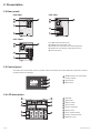
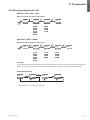
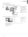
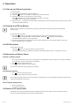
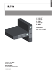
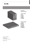
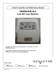
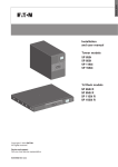
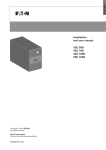
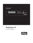
ENGLISH
Installation
and user manual
5SC
5SC
5SC
5SC
5SC
5SC
5SC
Copyright © 2013 EATON
All rights reserved.
Service and support:
Call your local service representative
619-00470-00-us (en)
500
750
1000
1500
500G
750G
1500G
Page 2
619-00470-00-us (en)
ENGLISH
IMPORTANT SAFETY INSTRUCTIONS
SAVE THESE INSTRUCTIONS. This manual contains important instructions
that should be followed during installation and maintenance of the UPS and batteries.
The 5SC models that are covered in this manual are intended for installation in an environment
within 0 to 40°C, free of conductive contaminant.
This equipment has been tested and found to comply with the limits for a Class A digital device,
pursuant to Part 15 of the FCC Rules. These limits are designed to provide reasonable protection against
harmful interference when the equipment is operated in a commercial environment. This equipment
generates, uses, and can radiate radio frequency energy and, if not installed and used in accordance
with the instruction manual, may cause harmful interference to radio communications. Operation of
this equipment in a residential area is likely to cause harmful interference in which case the user will
be required to correct the interference at his own expense.
Certification Standards
• UPS directives: UL 1778 4th edition (UL listed).
• Performance: IEC 62040-3: 2001.
• Radiated emission: FCC CFR 47 part 15 subpart B, Class A, VCCI.
• Surges withstand ability: IEEE ANSI C62.41 Category A2 (UL Listed).
VCCI Notice
Special Symbols
The following are examples of symbols used on the UPS or accessories to alert you to important
information:
RISK OF ELECTRIC SHOCK - Observe the warning associated with the risk of electric shock symbol.
Important instructions that must always be followed.
Do not discard the UPS or the UPS batteries in the trash.
This product contains sealed lead acid batteries and must be disposed as it's explain in this manual.
For more information, contact your local recycling/reuse or hazardous waste center.
This symbol indicates that you should not discard waste electrical or electronic equipment (WEEE)
in the trash. For proper disposal, contact your local recycling/reuse or hazardous waste center.
Information, advice, help.
619-00470-00-us (en)
Page 3
Safety of Persons
• The system has its own power source (the battery). Consequently, the power outlets may be energized
even if the systems is disconnected from the AC power source.
• Dangerous voltage levels are present within the system. It should be opened exclusively by qualified
service personnel.
• The system must be properly grounded.
• The battery supplied with the system contains small amounts of toxic materials.
To avoid accidents, the directives listed below must be observed:
- servicing of batteries should be performed or supervised by personnel knowledgeable about betteries
and the required precautions.
- when replacing batteries, replace with the same type and number of batteries or battery packs.
- do not dispose of batteries in a fire. The batteries may explode.
- batteries constitute a danger (electrical shock, burns). The short-circuit current may be very high.
Precautions must be taken for all handling:
• Wear rubber gloves and boots.
• Do not lay tools or metal parts on top of batteries.
• Disconnect charging source prior to connecting or disconnecting battery terminals.
• Determine if battery is inadvertently grounded. If inadvertently grounded, remove source from ground.
Contact with any part of a grounded battery can result in electrical shock. The likelihood of such shock
can be reduced if such grounds are removed during installation and maintenance (applicable to
equipment and remote battery supplies not having a grounded supply circuit).
Product Safety
• The UPS connection instructions and operation described in the manual must be followed in
the indicated order.
• A protection circuit breaker must be installed upstream and be easily accessible.
The system can be disconnected from the AC power source by opening this circuit breaker.
• Check that the indications on the rating plate correspond to your AC powered system and to
the actual electrical consumption of all the equipment to be connected to the system.
• For PLUGGABLE EQUIPMENT, the socket-outlet shall be installed near the equipment and shall
be easily accessible
• Never install the system near liquids or in an excessively damp environment.
• Never let a foreign body penetrate inside the system.
• Never block the ventilation grates of the system.
• Never expose the system to direct sunlight or source of heat.
• If the system must be stored prior to installation, storage must be in a dry place.
• The admissible storage temperature range is -15 ºC to +50 ºC.
• The system is not for use in a computer room AS DEFINED IN the standard for the Protection of
Information Technology Equipment, ANSI/NFPA 75 (US installations only).
Contact Eaton resellers to order a special battery kit, if needed to meet the ANSI/NFPA 75 requirement.
Special Precautions
• All handling operations will require at least two people (unpacking, installation in rack system).
• Before and after the installation, if the UPS remains de-energized for a long period, the UPS must be
energized for a period of 24 hours, at least once every 6 months (for a normal storage temperature
less than 25 °C). This charges the battery, thus avoiding possible irreversible damage.
• During the replacement of the Battery Module, it is imperative to use the same type and number of
element as the original Battery Module provided with the UPS to maintain an identical level of
performance and safety. In case of doubt, don’t hesitate to contact your EATON representative.
Page 4
619-00470-00-us (en)
1. Introduction........................................................................................ 6
1.1 Environmental protection....................................................................................................6
2. Presentation....................................................................................... 7
2.1 Standard installations..........................................................................................................7
2.2 Rear panels.........................................................................................................................7
2.3 Control panel......................................................................................................................8
2.4 LCD description..................................................................................................................8
2.5 UPS setting through the LCD.............................................................................................9
3. Installation....................................................................................... 10
3.1 Unpacking and contents check......................................................................................... 10
3.2 Battery module connection.............................................................................................. 10
3.3 Communication ports ...................................................................................................... 11
4. Operation......................................................................................... 12
4.1 Start-up and Normal operation.......................................................................................... 12
4.2 Starting the UPS on Battery............................................................................................. 12
4.3 UPS Shutdown................................................................................................................. 12
4.4 Operation on Battery Power............................................................................................. 12
4.5 Return of AC Input Power................................................................................................. 12
5. Maintenance.................................................................................... 13
5.1 Troubleshooting................................................................................................................. 13
5.2 Battery-module replacement............................................................................................ 14
6. Appendices....................................................................................... 15
6.1 Technical specifications..................................................................................................... 15
619-00470-00-us (en)
Page 5
ENGLISH
Contents
1. Introduction
Thank you for selecting an EATON product to protect your electrical equipment.
The 5SC range has been designed with the utmost care.
We recommend that you take the time to read this manual to take full advantage of the many features
of your UPS (Uninterruptible Power System).
Before installing your 5SC, please read the booklet presenting the safety instructions.
Then follow the instructions in this manual.
To discover the entire range of EATON products and the options available for the 5SC range,
we invite you to visit our web site at www.eaton.com/powerquality or contact your EATON representative.
1.1 Environmental protection
EATON has implemented an environmental-protection policy.
Products are developed according to an eco-design approach.
Substances
This product does not contain CFCs, HCFCs or asbestos.
Packing
To improve waste treatment and facilitate recycling, separate the various packing components.
• The cardboard we use comprises over 50% of recycled cardboard.
• Sacks and bags are made of polyethylene.
• Packing materials are recyclable and bear the appropriate identification symbol
01
PET
Materials
Abbreviations
Number in
the symbols
Polyethylene terephthalat
PET
01
High-density polyethylene
HDPE
02
Polyvinyl chloride
PVC
03
Low-density polyethylene
LDPE
04
Polypropylene
PP
05
Polystyrene
PS
06
01
PET
Follow all local regulations for the disposal of packing materials.
End of life
EATON will process products at the end of their service life in compliance with local regulations.
EATON works with companies in charge of collecting and eliminating our products at the end of
their service life.
Product
The product is made up of recyclable materials.
Dismantling and destruction must take place in compliance with all local regulations concerning waste.
At the end of its service life, the product must be transported to a processing center for electrical and
electronic waste.
Battery
The product contains lead-acid batteries that must be processed according to applicable local regulations
concerning batteries.
The battery may be removed to comply with regulations and in view of correct disposal.
Page 6
619-00470-00-us (en)
2.1 Standard installations
D
Description
H
W
5SC
5SC
5SC
5SC
5SC
5SC
5SC
500
750
1000
1500
500G
750G
1500G
Weights
(lb/kg)
15.0 / 6.8
23.6 / 10.7
25.1 / 11.4
34.4 / 15.6
14.6 / 6.6
22.9 / 10.4
33.5 / 15.2
Dimensions (inch/mm)
D xW x H
9.4 x 5.9 x 8.3 / 240 x 150 x 210
13.4 x 5.9 x 8.3 / 340 x 150 x 210
13.4 x 5.9 x 8.3 / 340 x 150 x 210
16.1 x 5.9 x 8.3 / 410 x 150 x 210
9.4 x 5.9 x 8.3 / 240 x 150 x 210
13.4 x 5.9 x 8.3 / 340 x 150 x 210
16.1 x 5.9 x 8.3 / 410 x 150 x 210
2.2 Rear panels
5SC 500
5SC 750
2
5
2
5
1
1
3
OUTPUT 120V~ 8.4AMAX
3
OUTPUT 120V~ 8.4AMAX
OUTPUT 120V~ 4.2AMAX
INPUT 100-120V~
4
INPUT 100-120V~
4
5SC 1000
5SC 1500
2
5
1
2
5
1
3
3
OUTPUT 120V~ 8.4AMAX
OUTPUT 120V~ 8.4AMAX
OUTPUT 120V~ 8.4AMAX
INPUT 100-120V~
INPUT 100-120V~
4
4
(1) USB communication port
(2) RS232 communication port
(3)Outlets for connection of critical equipment
(4)Attached 6 ft. input power cord for AC-power source
(5)Ground screw
619-00470-00-us (en)
Page 7
ENGLISH
2. Presentation
2. Presentation
2.2 Rear panels
5SC 500G
5SC 750G
2
2
5
1
5
1
3
OUTPUT 230V~ 4.6AMAX
3
OUTPUT 230V~ 2.3AMAX
INPUT 220-240V~
INPUT 220-240V~
4
4
Refer to the Bottom of
the unit for caution markings!
5SC 1500G
2
5
1
OUTPUT 230V~ 6.9AMAX
(1) USB communication port
(2) RS232 communication port
(3)Outlets for connection of critical equipment
(4)Socket for connection to AC-power source
(5)Ground screw
3
4
INPUT 220-240V~
2.3 Control panel
The UPS has a three-button LCD. It provides useful information about the UPS itself, load status, events,
measurements and settings.
7
ON/OFF button for the battery
backup outlets
Scroll down
8
Mute alarm
9
UPS ON
10
AVR mode
11
Battery mode
12
Internal fault
13
Output load level
14
Battery level
15
Input measurements
16
Output measurements
17
Measuring unit
6
6
AVR
%
Min
Hz
kVA
kW
7
8
2.4 LCD description
10
11
9
12
13
14
15
16
Page 8
17
619-00470-00-us (en)
2.5 UPS setting through the LCD
5SC 500 / 750 / 1000 / 1500
Release scroll down button to select menu
2s
5s
2s
Output voltage
Alarm
5SC 500G / 750G / 1500G
Release scroll down button to select menu
5s
2s
2s
Output voltage
Alarm
2s
Sensitivity
Sensitivity
In low sensitivity mode (Lo) UPS will tolerate more fluctuations in power and will go on battery power less
often. If the connected load is sensitive to power disturbances, keep the sensitivity as Standard (Std).
Example of setting
10s
5s
5s
Save the new value
• LCD shut off if no activity for 3 minutes.
619-00470-00-us (en)
Page 9
ENGLISH
2. Presentation
3. Installation
3.1 Unpacking and contents check
1
6
4
3
2
5
(1) 5SC UPS
(2) Quick start and safety instructions
(3) User manual and IPSS (Intelligent Power Software Suite) CD-ROM
(4) RS232 communication cable
(5) USB communication cable
(6) 2 connection cables for the protected equipments (500G, 750G and 1500G models)
Packing materials must be disposed of in compliance with all local regulations concerning waste.
Recycling symbols are printed on the packing materials to facilitate sorting.
3.2 Battery module connection
Caution: Before starting the UPS, please connect the internal battery.
Note: A small amount of arcing may occur when connecting the batteries.
This is normal and does not damage the UPS or present any safety concern.
A-R
emove front panel.
B-C
onnect the battery module
(never pull on the wires).
B
C - Attach the front panel.
A
C
Page 10
619-00470-00-us (en)
3.3 Communication ports
Connection of RS232 or USB communication port
The RS232 and USB communication ports cannot operate simultaneously.
1
1. C
onnect the RS232 (5) or USB
(6) communication cable to
the serial or USB port on
the computer equipment.
2
5
6
2. C
onnect the other end of the
communication cable (5) or
(6) to the USB (1) or RS232 (2)
communication port on
the UPS.
The UPS can now communicate
with EATON power management
software.
Characteristics of the optocouplers communication port (optional)
• Pins 1, 3, 4, 5, 6, 10: not used
• Pin 2: common (user)
• Pin 7: low battery
• P
in 8: operation on battery
power
• P
in 9: UPS ON, equipment
supplied
n.o.: normally open contact
When a signal is activated, the contact is closed between the common (pin 2) and the pin
for the corresponding signal.
Contact characteristics (optocoupler)
• Voltage: 48 V DC max
• Current: 25 mA max
• Power: 1.2 W
619-00470-00-us (en)
Page 11
ENGLISH
3. Installation
4. Operation
4.1 Start-up and Normal operation
To start the UPS:
1. Verify that the UPS power cord is plugged in.
2. Press the
button on the UPS front panel for at least 2 seconds.
3.Check the UPS front panel display for active alarms.
If the
indicator is on, do not proceed until all alarms are clear.
Correct the alarms and restart if necessary.
4.Verify that the
indicator illuminates solid, indicating that the UPS is operating normally and any loads
are powered and protected.
4.2 Starting the UPS on Battery
Before using this feature, the UPS must have been powered by utility power with output enabled
at least once.
To start the UPS on battery:
1.Press the
button on the UPS front panel until the UPS front panel display illuminates.
The UPS cycles through Standby mode to Battery mode. The
indicator illuminates solid.
The UPS supplies power to your equipment.
2.Check the UPS front panel display for active alarms. Resolve any active alarms before continuing.
See "Troubleshooting" on page 21.
4.3 UPS Shutdown
To shut down the UPS:
Press the
button on the front panel for three seconds.
The UPS starts to beep. The UPS then transfers to Standby mode, and the
indicator turns off.
4.4 Operation on Battery Power
Transfer to battery power
• The connected devices continue to be supplied by the UPS when AC input power is no longer available.
The necessary energy is provided by the battery.
• The
indicator illuminates solid.
• The audio alarm beeps every ten seconds.
The connected devices are supplied by the battery.
Low-battery warning
• The
indicator illuminates solid.
• The audio alarm beeps every three seconds.
The remaining battery power is low. Shut down all applications on the connected equipment because automatic UPS shutdown is imminent.
End of battery backup time
• All the LEDs go OFF .
• The audio alarms stops.
4.5 Return of AC Input Power
Following an outage, the UPS restarts automatically when AC input power returns (unless the restart
function has been disabled) and the load is supplied again.
Page 12
619-00470-00-us (en)
5.1 Troubleshooting
Operation status
Overload
Site wiring fault
Short-circuit fault
Battery fault
Fan fault
Charger fault
Possible cause
Action
Power requirements exceeds the
Remove some of the equipment
UPS capacity (greater than 105 % of from the UPS. The UPS continues
nominal).
to operate, but may shutdown
if the load increases.The alarm
resets when the condition becomes
inactive.
A Site Wiring Fault has occurred.
Have a qualified electrician correct
The outlet that the UPS is plugged
the wiring.
into is not properly grounded or
properly wired.
A short-circuit occurred on the
application.
Check application connection or
integrity.
The batteries in the UPS are
disconnected.
If error persists, note the alarm
message and the UPS serial
number, and then contact your
service representative.
Verify that all batteries are properly
connected.
If error persists, note the alarm
message and the UPS serial
number, and then contact your
service representative.
The end of battery life is reached.
Contact your service representative
for battery replacement.
The UPS has a fan fault.
Check that no object is blocking fan.
The UPS has a charger fault.
If error persists, note the alarm
message and the UPS serial
number, and then contact your
service representative.
The UPS does not charge the
battery anymore.
Note: note the alarm message and
the UPS serial number, and then
contact your service representative.
619-00470-00-us (en)
Page 13
ENGLISH
5. Maintenance
5. Maintenance
5.2 Battery-module replacement
Safety recommendations
The battery can cause electrocution and high short-circuit currents. The following safety precautions
are required before servicing the battery components:
• remove watches, rings, bracelets and all other metal objects from the hands and arms,
• use tools with an insulated handle.
Battery tray removal on tower models
This operation must be performed when the UPS is switched OFF, and unplugged from AC source.
A - Remove the front panel.
A
B-D
isconnect the battery-module by
separating the town connectors
(never pull on the wires).
B
C-R
emove the plastique protection cover
in front of the battery (one screw).
C
D
D-P
ull the plastic tab to remove
the battery block and replace it.
Mounting the new battery module
Carry out the above instructions in reverse order.
● To ensure safety and high performance, use only batteries supplied by EATON.
● Take care to firmly press together the two parts of the connector during remounting.
Page 14
619-00470-00-us (en)
6.1 Technical specifications
Filter
Transformer
"AVR"
Charger
Inverter
Battery
Output Power @ 120 V
Output Power @ 110V
Output Power @ 100 V
•Rated input voltage
•Input voltage range
•Input frequency range
•Voltage
•Frequency
5SC 500
500 VA
350 W
460 VA
325 W
415 VA
290 W
5SC 750
5SC 1000
5SC 1500
750 VA
1000 VA
1440 VA
525 W
700 W
1050 W
690 VA
920 VA
1320 VA
485 W
645 W
990 W
620 VA
830 VA
1200 VA
435 W
580 W
900 W
AC Input power
Single phase 100-125 V
96 to 144 V
45 to 55 Hz (50 Hz system), 55 to 65 Hz (60 Hz system)
Output on battery power
100/110/120 V (-10/+6 %) (1)
50/60 Hz ±0.1 Hz
Battery (sealed lead acid, maintenance free)
•Standard
1 x 12 V
7 Ah
2 x 12 V
7 Ah
2 x 12 V
9 Ah
3 x 12 V
9 Ah
Environment
•Operating temperature
range
•Storage temperature
range
•Relative humidity
0 to 35 °C / 32 to 95 °F
-15 to +40 °C / 5 to 104 °F
0 to 90 % (without condensation)
•Noise level
< 40 dBA
(1) Adjustable to 100/120/125 V, must be set to the identical AC power source value.
For 5SC Models - "CAUTION - To reduce the risk of fire, connect only to a circuit provided with 20 amperes
maximum branch circuit overcurrent protection in accordance with the National Electric Code,
ANSI/NFPA 70".
This product is designed for IT power distribution system.
619-00470-00-us (en)
Page 15
ENGLISH
6. Appendices
6. Appendices
Filter
Transformer
"AVR"
Charger
Inverter
Battery
Output Power @ 230 V
•Rated input voltage
•Input voltage range
•Input frequency range
•Voltage
•Frequency
•Standard
•Operating temperature
range
•Storage temperature
range
•Relative humidity
•Noise level
5SC 500G
5SC 750G
5SC 1500G
500 VA
750 VA
1500 VA
350 W
525 W
1050 W
AC Input power
Single phase 220-240 V
184 to 276 V
45 to 55 Hz (50 Hz system), 55 to 65 Hz (60 Hz system)
Output on battery power
220/230/240 V (-10/+6 %) (1)
50/60 Hz ±0.1 Hz
Battery (sealed lead acid, maintenance free)
1 x 12 V
2 x 12 V
3 x 12 V
9 Ah
7 Ah
9 Ah
Environment
0 to 35 °C / 32 to 95 °F
-15 to +40 °C / 5 to 104 °F
0 to 90 % (without condensation)
< 40 dBA
(1) Adjustable to 220/230/240 V, must be set to the identical AC power source value.
When the appliance is used in EU area, use an external circuit breaker in front of line with rating 16 A,
250 V which is IEC/EN 60898-1 standard compliant;
When the appliance is used in America area, use an external circuit breaker in front of line with rating 20 A,
250 V.
This product is designed for IT power distribution system.
Page 16
619-00470-00-us (en)