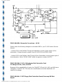
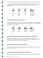
1
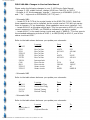
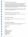
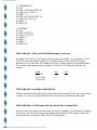
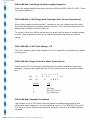
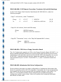
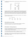
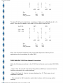
H/Z-100 Service Bulletins
H/Z-100 Field Service Bulletins
General Notes:
-- The following article appeared as an insert to issue #42, November-December
1995, of the "Z-100 LifeLine".
Z-100 Field Service Bulletins
Some of these bulletins contain out-of-date information, however, I left it in for two
reasons - I don't know for certain if the information still applies, and older machines
and publications are still out there to which the information may still apply - such as
the Z-100 Interim Service and the Service Data Manuals, which seem to be
completely different from the Z-100 Service Manual I received from Paul. Also, while
you may not have some of the manuals mentioned, I thought the information may
still be valuable for your other manuals or notes. Where I have updated information,
I have added it.- ed.
FSB-Z100-001: Disk Drive Specifications
The specifications in both the Service Data Manual and the Z-100 Product Info
Manual stated the disk controller will support up to four 8" drives and four 5.25"
drives. At that time, it was a hardware specification rather than a software
specification. Early software only supported 2 each of the 5.25" and 8" drives.
FSB-Z100-002: Blooming of Display
Some All-In-One computers exhibited "blooming" of the video display for about 20
seconds after turn on. This condition was considered normal.
FSB-Z100-003: Metal Filings in Cabinet
When a Z-100 microcomputer is disassembled, you may notice small metal filings on
the bottom of the cabinet on either side. These filings were from the self tapping
sheet metal screws that were used. Carefully remove any metal filings with a
vacuum cleaner or cloth. This problem has been corrected in later production by
using regular sheet metal screws.
http://home.earthlink.net/~z100lifeline/data/Service.html (1 of 21)7/4/2004 1:41:55 PM
H/Z-100 Service Bulletins
FSB-Z100-004: Changes to Service Data Manual
Please make the following changes in your Z-100 Service Data Manual:
- On page 3-159, middle column, change U219 from 74ALS74 to 74S74.
- On page 4-13, third paragraph, change "...logic zero on VDRAMSEL (U337-4)
and..." to "...logic zero on VIDRAMSEL (U377-4) and..."
- Schematic MB1:
-- Locate C178 & C179 at the crystal inputs to the 8085 CPU (U210). Note that
these capacitors may not be installed, as the crystal used at Y101 did not require
them to operate. (To my knowledge, these capacitors were never installed - ed.)
-- Locate U198-11 at the data output latch. This line connects to U220-12, so the
correct mnemonic is CPUWR, not CPUWR as indicated in an earlier update.
-- Locate U188-7 in the swap timing circuits and mark it "88SELD." This line goes to
the extended addressing circuits at U193-1, to NDEF(8088) at U215-2, and to the
status circuits at U226.
Refer to the table shown below as you update your schematic.
IC
U211-23
U219
U219
U220-12
U237D
U237D
U202-9
C189
D101
U226-13
U226-13
Location
8088 CPU
Bus Ctrl Out
Bus Ctrl Out
Bus Ctrl Out
Bus Ctrl Out
Bus Ctrl Out
Interrupt latch
Reset circuits
Reset circuits
Status circuits
Status circuits
From
Z
ALS74
443-1051
L
ALS74
443-1051
L
22/10
1N4149
A0
88SEL
To
H
S74
443-900
P
LS125
443-811
P
100uF
1N5817
A3
88SELD
- Schematic MB3
Refer to the table shown below as you update your schematic.
IC
U151-11
U170-10
U151-13
U167-8
Location
refrsh-Wait Timg
Refrsh-Wait Timg
Refresh Timing
Refresh Timing
From
H
H
H
H
To
P
P
P
P
- Schematic MB4
Refer to the table shown below as you update your schematic.
IC
U160-1 thru -8
U204-35
Location
Timer
Keyboard Encoder
http://home.earthlink.net/~z100lifeline/data/Service.html (2 of 21)7/4/2004 1:41:55 PM
From
Z
H
To
P
L
H/Z-100 Service Bulletins
- Schematic VB1
Locate VIDRAMDRY at P305-62 and remove the overbar. This line asserts on logic
one.
Refer to the table shown below as you update your schematic.
IC
U345-2
U345-4
U345-9
U345-19
U301-13
U337-1
U337-3
U337-14
U337-16
U371-14
Location
68A21 PIA
68A21 PIA
68A21 PIA
68A21 PIA
Paral/Ser.Conv.
Timing & Ctrl
Timing & Ctrl
Timing & Ctrl
Timing & Ctrl
VRAMSEL PROM
From
L
L
L
L
Q4
L
L
P
P
L
To
H*
H*
H
H
QH
H*
H*
L*
L*
H
- Schematic VB3
Refer to the table shown below as you update your schematic.
IC
U307
Location
RGB driver
From
F244
To
LS244
- Z207 Schematic
Locate the lower portion of U9 (near the 5" interface connector) and change the
buffer symbol as follows:
FSB-Z100-005: Z-207 Floppy Disk Controller Card
More Efficient Heat Sink Grease
To allow a more efficient transfer of heat from regulator (PS3) to the heat sink, the
silicone grease (HE 352-13) was replaced with thermal compound (HE 352-31). To
correct your Z-100 Service Manual, page 5-180, second column, change "silicone
grease HE 352-13" to "Thermal compound HE 352-31."
http://home.earthlink.net/~z100lifeline/data/Service.html (3 of 21)7/4/2004 1:41:55 PM
H/Z-100 Service Bulletins
FSB-Z100-006: Test Operates Erratically
When the H/Z-100 is disassembled and reconnected with extended length cables to
be used as a test bed, the unit may operate erratically, making it difficult to
troubleshoot. Symptoms include failure to boot a disk, or the CRT may print
characters at the wrong baud rate, or the CRTC may not initialize properly, among
others. One cause may be the length of the two 40-pin ribbon cables connecting the
video board to the motherboard. If not positioned properly, these cables will pick up
noise from other cables or from the video monitor.
In most cases, you can correct the problem by routing the ribbon cables under the
chassis and video board. If this doesn't correct the problem, then replace the two
cables with 40-pin shielded ribbon cables.
FSB-Z100-008: New Connectors at P104 and P106
The 40-pin connectors at P104 and P106 on the motherboard were changed to
remove pin 7 for P104 and pin 47 for P106.
FSB-Z100-009: Power Supply
The power supplies were changed to incorporate the extra cable needed for the
Winchester Controller.
FSB-Z100-010: Video Alignment
When aligning a monitor used with a Z-100 microcomputer, there are four short
programs you may use under ZBASIC to help in video alignment:
10
20
30
40
'WHITE SCREEN
CLS
PAINT (0,0),7
END
10 'RGB
20 CLS
30 LINE (0,175)-(640,175),1
40 LINE (0,75)-(640,75),1
50 LINE (320,0)-(320,75),1
60 PAINT (0,0),4,1
70 PAINT (330,0),2,1
80 PAINT (0,80),7,1
90 PAINT (0,200),1,1
100 END
http://home.earthlink.net/~z100lifeline/data/Service.html (4 of 21)7/4/2004 1:41:55 PM
H/Z-100 Service Bulletins
10
20
30
40
50
60
70
80
90
'CROSSHATCH
CLS
FOR I=0 TO 640 STEP 30
LINE (I,0)-(I,240),7
NEXT I
FOR I=0 TO 250 STEP 15
LINE (0,I)-(630,I),7
NEXT I
GOTO 90
10
20
30
40
50
60
70
80
'DOTBAR
CLS
FOR I=0 TO 39
FOR L=0 TO 24
PRINT ".";
NEXT L
NEXT I
GOTO 80
FSB-Z100-011: J101 and J102 ROM Jumpers Incorrect
On page 2-20 of the Z-100 Interim Service Manual (HE 860-15) and page 3-10 of
the Z-100 Service Manual (593-75), the table showing J101 and J102 jumper
positions for the 16K and 32K ROMs is incorrect. Shown below is a corrected table.
The jumper descriptions given on page 2.4 of the Z-100 Technical Manual are
correct.
ROM
2764 (8K)
27128 (16K)
27256 (32K)
J101
0
0
1
J102
0
1
1
FSB-Z100-012: Unreliable 64K RAM ICs
Texas Instruments 64K RAM chips, date coded from 8146 to 8236, may not operate
reliably. To correct, replace these ICs with ones having a different date code.
FSB-Z100-013: Z-120 Beeps, But Fan Won't Run; Vertical Roll
Check to see if the sweep circuit board is properly installed. If this board is installed
incorrectly, the foil side of the circuit board may touch the CRT support panel and
short out the circuit board. FSB-Z100-045 also applies.
http://home.earthlink.net/~z100lifeline/data/Service.html (5 of 21)7/4/2004 1:41:55 PM
H/Z-100 Service Bulletins
FSB-Z100-014: Unit Hangs Up After Lengthy Operation
Check the programmable interrupt controllers U208 and U209 (HE 443-1012). These
ICs may be defective.
FSB-Z100-015: Z-207 Floppy Disk Controller Card; 12-volt Line Shorted
Some ribbon cables connecting the 8" interface to the rear chassis have too much
wire protruding past the controller board connector. This extra wire may pierce the
board resist and short to the 12 Vdc line.
To correct, either trim off the excess wire, or wrap it with a piece of insulating tape,
or both. Later production runs have a new 50-wire cable that does not require
taping.
FSB-Z100-016: Z-207 Parts Change - C6
The 10 uF capacitor at C6 was changed to a 33 uF capacitor to decrease the number
of soft errors.
FSB-Z100-017: Floppy Controller Won't Access Drives
Check switch DS1 on the floppy controller card for proper installation and switch
settings. Looking at the board with the S-100 connector pins at the bottom, these
are:
ON
OFF
(1)
(0)
7 6 5 4 3 2 1 0
X
X X
^ Up
X
X X X X
Section:
0
1
2
3-7
Use:
TPI
PreComp
Not Used - Set at 0
Port Addressing
FSB-Z100-018: Checkout Procedures
Logic states in the Z-100 Interim Service Manual troubleshooting sections and
schematics were measured in a unit containing version 1.0 of MTR100. Since the Z100 Interim Service Manual was published, several revisions to this ROM had been
released.
http://home.earthlink.net/~z100lifeline/data/Service.html (6 of 21)7/4/2004 1:41:55 PM
H/Z-100 Service Bulletins
In some of these revisions, the firmware will either initialize a circuit that wasn't
previously initialized or initialize it differently than before. The result is that the logic
states in these circuits may not match those shown in the Z-100 Interim Service
Manual.
In the Interim Service Manual, HE 860-15, volume one, there is a procedure
outlined on pages 2-112 and 2-113 describing power measurements of the power
supply with the supply unloaded. DISREGARD THIS PROCEDURE. When a switching
power supply is unloaded, the voltage measurements are unreliable. Therefore
perform any required voltage measurements with all modules connected, or use a
suitable power supply load.
FSB-Z100-019: ZW-120 Hard Drive Causes Floppy Disk Errors
Floppy disk errors in a Winchester environment may be caused by EMI radiating
from the hard drive to the floppy disk drive. To correct this problem, secure a shield
to the bottom of the Winchester drive. The shield was installed on later production
runs.
FSB-Z100-021: IC Change at U218
To permit the use of a multi-sourced part, the 96LS02 IC (HE 443-1040) at U218
was changed to a 9602 IC (HE 443-1112) on later production runs. This was not a
modification and the change was not required.
FSB-Z100-022: Dim Display
When troubleshooting a color video board, make sure that control R301 is in its fully
CCW position as viewed from the component side of the board. If this control has
been adjusted by the customer to a position other than CCW, a dim display may
result.
FSB-Z100-023: Changed Power Supply Part Numbers
The part numbers for the power supplies for the Low Profile Computer was changed
from HE-234-257 to HE 234-319 and for the All-In-One, from HE 234-256 to HE 234320.
FSB-Z100-024: Z-207 Floppy Disk Controller Card Soft Error Reduction
Connect a 10 uF capacitor in parallel with the 0.1 uF capacitor at C32. Be sure the
http://home.earthlink.net/~z100lifeline/data/Service.html (7 of 21)7/4/2004 1:41:55 PM
H/Z-100 Service Bulletins
positive and negative leads of the 10 uF capacitor are positioned to the left of the
component side of the board (with the 100-pin connector down).
This update was performed only "as needed." (I don't know about earlier boards, but
the 85-2807-2 and -3 boards already have both capacitors installed, as C32 and C321. Check earlier boards, the -1 board also may have it installed - ed.)
FSB-Z100-025: Reprint of FSB-Z100-011
FSB-Z100-026: Z-100 Interim Service Manual Corrections
Please make the following corrections to the Z-100 Interim Service Manual:
- Page 3-104: In the second & third paragraphs, cross out "video board" and write in
"motherboard."
- Page 3-120: Fifth step from the bottom, change "U152-13 = L" to "U152-13 = P."
- Schematic MB3: Locate U170; this is a dual 4-input NAND gate in the refresh
timing and the wait timing circuits. Cross out "ALS40" and replace it with "ALS1020."
- Z-207 Floppy Disk Controller Schematic:
-- Locate the INTRQ line at U22-39 and trace it left to U25-3 (next to RP3-2).
Change U25-3 to U25-13.
-- Locate the two inverter sections labeled "U28" beside "U15" and "U14" on your
schematic (see the following figure) and change to "U10."
http://home.earthlink.net/~z100lifeline/data/Service.html (8 of 21)7/4/2004 1:41:55 PM
H/Z-100 Service Bulletins
-- Locate U22-38. Change "ORG" to DRQ."
-- To make the schematic agree with the printed circuit board, change the schematic
jumper numbers as follows:
FROM
(Schematic):
J1 - J8
J9
J10
TO
(Circuit Bd):
J3 - J10
J1
J2
Schematic
Location:
Interrupt Jumpers
Near U19 (RDY delay)
Near U11-1 on 8"/5" line
- On page 7.12 and 12.34 of the Z-100 Interim Service Manual, add the following
commands to the Command Summary charts appearing on these pages.
Command
Enable Interrupts
Disable Interrupts
Code (Hex)
0C
0D
FSB-Z100-027: System Crashes When Winchester Is Installed
This may be caused by the HE 444-151 (U28) and HE 444-152-2 (U29) PALs on the
Winchester controller board. Under certain circumstances, these PALs may cause a
glitch on pin 19 (CDSB*) of the S-100 bus, causing memory failure.
To correct this condition, replace the HE 444-151 and HE 444-152-2 PALs with HE
444-151-1 and HE 444-152-3 PALs respectively. Replace both parts together, as
they are a set. Replace these parts on all units.
FSB-Z100-028: Z-205 Manual Correction
Superseded by FSB-Z100-036.
FSB-Z100-029: Z-100 Schematic Corrections
Please make the following changes to your Z-100 Interim Service Manual (HE 86015) schematics:
- Schematic MB3: At U126 (upper left corner of the schematic), change "TRI-STATE
OCTAL LATCH" to "TRI-STATE OCTAL BUFFER."
- Schematic VB1: The two NOR gates at U379 in the CRTC/CPU arbitration logic
(lower left corner of the schematic) are marked with two part numbers: HE 443http://home.earthlink.net/~z100lifeline/data/Service.html (9 of 21)7/4/2004 1:41:55 PM
H/Z-100 Service Bulletins
1045 and HE 443-1075. Cross out part number HE 443-1075.
FSB-Z100-030: Z-207 Manual Correction; Transistor (Q2 and Q3) Markings
In the Z-207 Floppy Disk Controller Card Manual HE 595-2909-01, make the
following changes:
- Page 7: Left column, under "Transistors",
Change:
To:
C3
C3
417-937
417-937
2
2
MPS2369
MPS2369 or PN2369A
Q2, Q3
Q2, Q3
- Page 18: Left column, fourth and fifth steps,
Change:
To:
...MPS2369 transistor...
...MPS2369 or PN2369A transistor...
- Page 59: "Transistors" chart, in the "May Be Replaced With" column,
Change:
To:
MPS2369
MPS2369 or PN2369A
FSB-Z100-031: C35 Fails on Floppy Controller Board
The 10 uF electrolytic capacitor at C35 on the Floppy Controller Board, 85-2807-1, is
being installed backwards because of incorrect circuit board screening and incorrect
instructions in the assembly manual and the HE 591-4245 manual insert. So, on any
HE 85-2807-1 board received for service, install the capacitor at C35 with the "+"
lead connected to pin 21 of U22. The 85-2807-0, -2, and -3 controller boards are
correct.
FSB-Z100-032: Winchester Disk Drive Configuration
Some confusion has arisen on proper configuration of replacement Winchester disk
drives for operation within H/Z-100 computers. As shipped, the 16-pin programming
plug usually has all pin pairs shorted with the possible exception of pin pairs 3-14
and 4-13. To eliminate confusion while configuring the programming plug, a
configuration guide is given below. Refer to the guide when replacing Winchester
disk drives in these units.
http://home.earthlink.net/~z100lifeline/data/Service.html (10 of 21)7/4/2004 1:41:55 PM
H/Z-100 Service Bulletins
To configure the Winchester disk drive, select the proper hardware unit and refer to
the table below:
Pin Pair:
1-16
2-15
3-14
4-13
5-12
6-11
7-10
8-9
Hardware Unit Number
1
2
Open
Open
Short
Short
Factory Set
Factory Set
Open
Open
Open
Open
Open
Short
Short
Open
Pin pairs 3-14 and 4-13 are set at the factory and the programming plug is properly
configured for the drive in which it is installed. However, if you move programming
plugs from drive to drive, there is a chance that the drive will not operate properly
due to improper configuration of these pins. If you must replace a programming plug
on a drive, refer to the chart below for proper configuration of pin pairs 3-14 and 413.
To use the chart, you must have the phase code of the disk drive. This is located on
a label on the disk drive case.
Pin Pair:
3-14
4-13
Phase Code
C
D
Open
Open
Open
Short
E
Short
Open
F
Short
Short
FSB-Z100-033: New Drive Shields
Later production runs of the Z-110 Low-Profile series computers used different
shields to provide greater vertical clearance for easier assembly.
FSB-Z100-034: Z-120 Display Brightness
The HE 57-27 diode used at CR-107 on the video monitor boards of the Z-120 All-InOne model caused the brightness to change with temperature. This was especially
noticeable in background raster brightness.
To correct this problem, replace the HE 57-27 diode at CR-107 with diode HE 234353. This diode is faster and less sensitive to temperature variation.
Replacement of an HE 57-27 with an HE 234-353 at CR-107 will shift the power
supply voltage more negative and will require readjustment of both R-139 "Brite"
and R-148 "Focus" controls.
http://home.earthlink.net/~z100lifeline/data/Service.html (11 of 21)7/4/2004 1:41:55 PM
H/Z-100 Service Bulletins
FSB-Z100-035: Z-205 Configuration Help
In order to help clear up some misunderstandings about the Z-205, the following
information will aid in setting up the proper configuration for any Z-100 use. (FSBS100-001 attempted further clarification and is incorporated in this discussion - ed.)
Later Z-205 boards used a different style DIP switch that caused additional
confusion when configuring this card. Early manuals showed drawings of the earlier
style DIP switches showing a "0" position, while the new DIP switches showed an
"ON" (shorted) in this position. Looking at the component side of the Z-205 card,
with the 100 pin connector at the bottom, the right side of the switches are "ON"
and are shorted. For the discussion below, a "1" represents an open section.
The Main Board on the Z-100 must be fully populated with 192K RAM in order for
any unmodified Z-205 card to function. The RAM located on the Main Board are
Banks 0, 1, and 2.
The FIRST Z-205 card added becomes RAM Banks 3, 4, 5, and 6. SW1 is set to the
address of 98h and since the first Bank on the card is 3, then SW2 is set to 03h (The
suffix h stands for Hex). The settings are:
1st Z-205:
SW2 = 03h
SW1 = 98h
0
1
2
3
4
5
6
7
SW2
*-*--
OFF
SW1
--*
--*
--*
--*
--*
--*
/ON
0
1
2
3
4
5
6
7
--*
--*
--*
*-*---*
--*
*-OFF
/ON
Note: Position 0 on each switch is the LSB, therefore for SW1 to be 98h:
Hex
Binary
SW1 positions:
9
1001
7654
8
1000
3210
The second Z-205 card installed has an address of 99h, having RAM Banks 7, 8, 9,
and A. Since the first bank on the card is 7, then SW2 is set to 07h.
2nd Z-205:
SW2 = 07h
SW1 = 99h
0
1
2
3
http://home.earthlink.net/~z100lifeline/data/Service.html (12 of 21)7/4/2004 1:41:55 PM
SW2
*-*-*--
SW1
--*
0
1
2
3
*---*
--*
*--
H/Z-100 Service Bulletins
4
5
6
7
OFF
Hex
Binary
SW1 positions:
--*
--*
--*
--*
/ON
9
1001
7654
4
5
6
7
*---*
--*
*-OFF
/ON
9
1001
3210
The third Z-205 card installed has an address of 9Ah, having RAM Banks B, C, D,
and E. Since the first bank on the card is B, then SW2 is set to 0Bh.
2nd Z-205:
SW2 = 0Bh
SW1 = 9Ah
0
1
2
3
4
5
6
7
SW2
*-*---*
OFF
Hex
Binary
SW1 positions:
SW1
*---*
--*
--*
--*
/ON
9
1001
7654
0
1
2
3
4
5
6
7
--*
*---*
*-*---*
--*
*-OFF
/ON
A
1010
3210
Note: The third card expansion may not provide expansion memory for all
applications due to accessing the video RAM.
FSB-Z100-036: Z-205 User Manual Corrections
Make the following corrections to the Z-205 User's Manual, part number 595-299001:
- Page 8: The 4th and 5th steps describing SW1 and SW2 are incorrect. See the
following information for correct settings.
- Page 9: On Inset #1 there is a jumper displayed on J3. This jumper is not
supposed to be there.
-- The pictorial for SW1 (switch on right side) is shown with the wrong switch
settings.
http://home.earthlink.net/~z100lifeline/data/Service.html (13 of 21)7/4/2004 1:41:55 PM
H/Z-100 Service Bulletins
- Page 11: Under SW1, the example shown is not representative of proper
configuration necessary for the Z-100.
- Page 15: The FILL routine will only work with ROM versions 2.2 or later. For earlier
version, one must use the CHKDSK utility.
- Page 16: Under "Final Configuration, Multi-card", correct the first statement to
read as follows:
-- Set dip switch SW1 positions 7, 4, 3, and 0 to the OFF (1) (LEFT) position. Set all
the others to the ON (0) (RIGHT) position.
- Add the following statement directly under the above correction:
-- Set dip switch SW2 positions 2, 1, and 0 to the OFF (1) (LEFT) position. Set all
the others to the ON (0) (RIGHT) position.
This will allow a user to operate two or more Z-205 memory cards (256K) in a
contiguous mode, allowing the full 768K memory addressing ability of the Z-100
series computers to be implemented.
FSB-Z100-037: Z-120 All-In-One Video Problem
If the prompt appears in the upper right corner, the video is smeared, and/or the
display is backwards, check for proper installation or operation of Q103 (HE 234276) and replace as necessary.
FSB-Z100-038: Interim Service Manual Schematic Update
On newer versions of the Z-100 main board, HE 181-4106, 181-4507, 181-4920,
181-5743, and higher, a section of U130 (443-1049) is inserted into the Refresh
Timing and Arbitration circuit. This section of U130 replaces a section of U168 used
on the old main boards (HE 181-3630). To update your MB3 schematics, refer to the
pictorial below and draw in the section of U130.
http://home.earthlink.net/~z100lifeline/data/Service.html (14 of 21)7/4/2004 1:41:55 PM
H/Z-100 Service Bulletins
FSB-Z100-039: Schematic Corrections - U130
Please make the following changes to schematic MB3 in your Z-100 Interim Service
Manual.
- Locate U130 in the Refresh Timing and Arbitration circuits (upper center of the
schematic). Change the part number from HE 443-1039 to HE 443-1049.
- Locate U130 in the Refresh, Wait Timing & Error-Generation circuits (upper right of
the schematic). Write "HE 443-1049" below the generic number (ALS37).
FSB-Z100-040: Z-217-1 Winchester Disk Controller Card
IC Change at U41, U45, and U48
Because of the unavailability of parts, the 74ALS273 ICs at U41, U45, and U48 were
changed to 74LS273 ICs. This was not a modification and older boards do not
require this change.
FSB-Z100-041: Z-207 Floppy Disk Controller Board; Precomp Will Not
Adjust
http://home.earthlink.net/~z100lifeline/data/Service.html (15 of 21)7/4/2004 1:41:55 PM
H/Z-100 Service Bulletins
If the pulse width at CP3 cannot be adjusted, or is missing, check for an open circuit
to U3-17 or an open wiper at R3.
FSB-Z100-042: Z-207 Floppy Disk Controller Card
Schematic Corrections - U22 and RP3
On the Floppy Disk Controller schematic (#585-21) supplied with the Z-100 Series
Technical Manual, the line marked "EARLY" on U22 should be pin 17 instead of pin
19.
On the yellow Floppy Disk Controller schematic supplied with the H/Z-100 Service
Data Manual, the control connected to U3-17 should be marked R3 instead of RP3.
FSB-Z100-043: Winchester Data Separator Card Shorts
When J4 is plugged into the data separator circuit board, the board may flex
downward, shorting out the supply voltages.
To eliminate this problem, remove the data separator circuit board from the top of
the drive brackets and install a piece of fish paper to the rear of the Winchester
drive shield. Reinstall the data separator board.
FSB-Z100-044: Z-120 Video Board
The video board for the Z-120 series microcomputers are close look-alikes to the Z29's. They are not interchangeable! The correct P/N for the Z-120 is A-10520 or A10648.
FSB-Z100-045: Z-120 Video Deflector Board Insulators
The video deflection board insulators were lengthened in later Z-120 All-In-One
models to eliminate the possibility of shorts occurring between the board and
chassis.
FSB-Z100-046: Z-100 Won't Start Up With Modem Connected.
Superseded by FSB-Z100-057.
http://home.earthlink.net/~z100lifeline/data/Service.html (16 of 21)7/4/2004 1:41:55 PM
H/Z-100 Service Bulletins
FSB-Z100-047: CP/M Won't Boot Properly
The 12H6 PAL IC (HE 444-128) at U186 on the motherboard has frequently caused
the CP/M booting problems.
On the motherboard (HE 85-2653-1), check Y101 (10 MHz crystal, HE 404-645), for
proper frequency and output. Also, check U210 (8085 CPU, HE 443-1010) for poor
socket contact or defective IC.
FSB-Z100-048: "Interrupt Circuit Error - U208" Displayed on Power Up
or Appears Intermittently
On the motherboard, check the foil lead going to U114, pin 10. This foil is cut as a
modification, but may not have been completely removed. A small piece of this foil
might be touching U114, pin 7, causing the interrupt error.
FSB-Z100-049: "Timer Error - U160" Displayed on Power Up
or Appears Intermittently
On the motherboard, check U191 (4.00 MHz oscillator module, HE 150-132) for
proper frequency and output.
FSB-Z100-050: Z-120 Low Video Brightness
A defective U337 (HAL14H4, HE 444-115) or U329 (74SL174, HE 443-1053) on the
video board may cause this problem.
FSB-Z100-051: Z-120 Video Board Loads Motherboard
A defective U369 (82S129), HE 444-103), U370 (TBP18S22, HE 444-127), or U371
(82S129, HE 444-102) on the Z-120 video board may load down the motherboard.
FSB-Z100-052: Drive Cross-Reference
Most Z-100 computers used a generic number for the drives installed. In later
models, to ease identification of the drive(s) in each unit, a label was applied to the
computer rear panel showing the last three digits of the drive part number, with the
Winchester digits first.
"Drive Type 163" indicates an HE 150-163 drive is installed, while "Drive Type
http://home.earthlink.net/~z100lifeline/data/Service.html (17 of 21)7/4/2004 1:41:55 PM
H/Z-100 Service Bulletins
156163" indicates an HE 150-156 Winchester and HE 150-163 floppy are installed.
A cross-reference of drive numbers is provided below. Any Z-100 series computer
not having a drive code have an HE 150-142 floppy and/or an HE 150-156
Winchester.
Drive
Code:
156
163
164
167
168
169
Model
Type:
Winc
Flop
Winc
Winc
Flop
Flop
Upgrade
Kit:
Z-217-2
Z-207-7
Z-217-21
----Z-207-71
-----
Part
Number:
HE 150-156
HE 150-163
HE 150-164
HE 150-167
HE 150-168
HE 150-169
FSB-Z100-053: Cabinet Cross-Reference
The cabinet parts for the Low Profile and All-In-One computers were standardized in
later production. The old and new part numbers are listed below. Each new part was
aluminized for RFI shielding.
Cabinet
Part:
Cover
Bottom
Cover
Center
Model:
LoPro
All
AIO
AIO
Old
Part #:
HE 92-758
HE 92-759
HE 92-761
HE 92-762
New
Part #:
HE 92-790
HE 92-791
HE 92-792
HE 92-793
FSB-Z100-054: Z-120 Video Monitor Board; Q401 Has Two Numbers
Q401 (HE 234-273) on the Z-120 video monitor board can be either type HE 1211058 or HE 121-1034. Please note this in your Z-100 Service Data Manual, video
monitor parts list, page 6-19, and on the schematic.
FSB-Z100-055: New S-100 Card Cage Bracket
A universal card cage bracket accommodating both half-height and full-height drives
was used in later models.
FSB-Z100-056: Motherboard SW101 Has Two Styles
Newer (HE 181-4106) motherboards used a different style DIP switch at SW101 to
http://home.earthlink.net/~z100lifeline/data/Service.html (18 of 21)7/4/2004 1:41:55 PM
H/Z-100 Service Bulletins
permit machine insertion of the part.
FSB-Z100-057: Z-100/RS-232 Modification
A situation may occasionally be experienced with ZW-110/120 models that requires
a modification to the RS-232 portion of the Main Board as follows:
- Symptom: Ports J1 and J2 do not function if modem is powered up prior to the Z100 being powered up.
- Analysis: Some modems have been found to place a negative voltage on the +12
V line from U228 on the motherboard. This keeps the +12v regulator from turning
on and the DTR line is in a transition state between On and Off.
- Solution: Install a diode, P/N HE 56-89, across C203 on Main Board. Note: The S100 card cage should be removed prior to the installation of the diode. It is
recommended to install the diode on the component side. The diode was installed in
production models as of August 1, 1983.
(Surprisingly, my newer motherboards, HE 181-5743, stamped 85-2806-1 in the
center, did not have this modification, but I have no idea as to their date of
manufacture - ed.)
Some other miscellaneous Field Service Bulletins that may be of interest:
FSB-DK-024: Z-207-41/42 8" Drive Configuration
Some confusion has arisen on the proper positioning of the MT/SR jumper on the 8"
floppy disk drives. When using the disk system with ZDS computers, make sure the
jumper is in the MT position. Also make sure the software you are using meets this
criteria: Z-DOS BIOS version 1.10, Format version 1.6 or higher, and/or CP/M
2.2.101 or higher. The use of older software will cause incompatibility with the disk
drive jumpering and BDOS and/or Format errors will result.
FSB-DK-025: H/Z-207 Erratic Write Operation
Circuit board #85-2807 for the H/Z-207 included base resistors for Q2 and Q3 to
eliminate any write irregularities. On older boards, if replacing Q2 and Q3 (#417937) does not correct the problem, install a 100 ohm resistor in series with the base
lead of Q2 and Q3. Install the resistors only when needed.
FSB-DK-027: Z-207 Controller Errors
http://home.earthlink.net/~z100lifeline/data/Service.html (19 of 21)7/4/2004 1:41:55 PM
H/Z-100 Service Bulletins
If "Device Controller Error" is presented or there is no prompt, check DS1 (HE 60621) for incorrect markings. A number of switches have been found to be
mismarked, or assembled with the cover upside down. A quick check is to check
continuity of each section. When DS1 is set as required, sections 0-3 and 6 should
be shorted when positioned toward the bottom of the board; all others open.
If the Z-207 controller will boot CP/M 85 and 86, but gives an I/O error for Z-DOS,
check U31 (74LS365A, HE 443-1039) for a defective gate; also DS1 (HE 60-621) for
switch "0" in the wrong position or open.
FSB-GEN-021: Winchester Notes
The following are general information notes that may help you solve problems and
understand the product better.
- When the winchester drive is replaced, it first has to be prepped. After prep is
completed there is a 50% ZDOS and a 50% CP/M partition set up on the disk.
Perform a CTRL-RESET on the machine, boot up on the winchester, and the
response will be a Hand Prompt on the screen with no message. This response
means 1) prep worked, 2) the disk can be written to, 3) the disk can be read.
Therefore the winchester drive is good.
- Under software control, the prep utility will keep track of the bad sectors. The
maximum allowable bad sector count is 168.
- If excessive soft errors are encountered on a system that works satisfactorily (it
preps, reads, writes, etc.), the problem usually will be alignment of the Data
Separator card. This card requires a scope with a 350 MHz bandwidth to perform the
alignment.
- Be careful when reconnecting the cables to the Winchester controller card. If the
leftmost ribbon connector is misconnected to the left, then a transistor located
directly to the right of the connector, Q101, will be blown. If this happens, it will not
be possible to initialize or write to the winchester drive and under ZDOS there will be
write error messages, and under Prep there will be a "Track Zero Has Bad Sectors"
message.
- If a problem develops in a system and gives parity or Bus error messages, and
dumps registers of the 8088 to the Bus; or if there is a total lock-up of the system
(dies for no apparent reason); either of these symptoms can be caused by a faulty
pair of PAL ICs, U28 and U29, in the lower left area of the controller card.
FSB-MON-002: ZVM-124 Monitor Servicing
The ZVM-124 is the same monitor as the ZVM-122/123 but is painted to match the
IBM colors. For service information, refer to the SM-ZVM-122/123 service manual.
http://home.earthlink.net/~z100lifeline/data/Service.html (20 of 21)7/4/2004 1:41:55 PM
H/Z-100 Service Bulletins
FSB-MON-004: ZVM-135 Color Monitor w/Dark Vertical Band
If a dark vertical band, approx 1/2" wide, develops on the CRT's left edge, it may be
caused by the CRT's blanking signal. If this problem appears, perform the following
modification:
- Remove the 9-227 module and replace R3473 (3.9K) with a 10K resistor. Reinstall
the 9-227 module.
- Adjust for proper width and centering by filling the screen with characters, either
with the Z-100 monitor ROM Fill command or using a BASIC program, then:
-- Turn the G2 control up to view the retrace lines,
-- Adjust the width control until the black bar disappears to the left side,
-- Adjust the Centering until the right side of the screen pattern is on the screen,
otherwise 0% over-scan.
-- Turn the G2 control for normal viewing.
NOTE: Do this modification whenever a Toshiba CRT is replaced with a Zenith CRT.
--- Steve Vagts, Editor, "Z-100 LifeLine"
[email protected]
HOME
Page
LifeLine
Page
Z-100
Page
Copyright © 2003, Steven W. Vagts
Revised -- January 30, 2003
http://home.earthlink.net/~z100lifeline/data/Service.html (21 of 21)7/4/2004 1:41:55 PM
Repair
Page