1
IM-P405-39
4058152/4
AB Issue 4
BT1050
Boiler Blowdown Timer
Installation and Maintenance Instructions
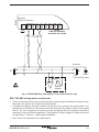
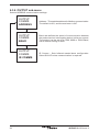
Commissioning password
Current legislation states that in order to prevent tampering and potentially
hazardous programming errors, access to the pass codes required to enter
commissioning mode should only be available to qualified and trained
personnel.
Enter commissioning
This is done from the run mode by pressing and holding down the
for 5 seconds.
PASS CODE
1. Safety information
2. User instructions and
delivery information
BT1050
button
The run mode display will disappear and the display
will show 'PASS CODE' with '8888' at the bottom
right corner of the screen. The flashing leading digit
indicates the position of the cursor. The default,
or factory set pass code is 7452 but this can be
changed from within the commissioning mode. The
pass code can be entered by using the
and
buttons to increase or decrease the flashing value
and the
and
buttons to move the cursor.
Pressing the OK button will enter the pass code. If an
incorrect pass code is used, the display automatically
returns to the run mode.
3. System overview
4. Mechanical installation
OK
8888
5. Electrical installation
6. Commissioning
- Quick set-up
- Full
7. Communications
8. Maintenance
9. Fault finding
OK
10. Technical information
- Default settings
This page MUST be removed
after commissioning
and kept in a safe,
access controlled location.
11.Appendix
- Summary of the Modbus protocol
12. Menu map
© Copyright 2013
Printed in GB
IM-P405-39 AB Issue 4
1. Safety information
Safe operation of this product can only be guaranteed if it is properly installed,
commissioned, used and maintained by qualified personnel (see Section 1.11) in
compliance with the operating instructions. General installation and safety instructions
for pipeline and plant construction, as well as the proper use of tools and safety
equipment must also be complied with.
Your attention is drawn to IEE Regulations (BS 7671, EN 12953, EN 12952 and EN 50156).
Elsewhere, other regulations will normally apply.
All wiring materials and methods shall comply with relevant EN and IEC standards
where applicable.
Warning
This product is designed and constructed to withstand the forces encountered
during normal use. Use of the product other than as a boiler controller, or failure
to install the product in accordance with these Instructions, product modifications
or repair could:
-
-
-
Cause injury or fatality to personnel.
Cause damage to the product / property.
Invalidate the
marking.
These instructions must be stored in a safe place near the product installation at all
times.
Warning
This product complies with Electromagnetic Compatibility Directive 2004 / 108 / EC
and all its requirements.
This product is suitable for Class A Environments (e.g. industrial). A fully detailed EMC
assessment has been made and has the reference number UK Supply BH BT1050 2008.
The product may be exposed to interference above the limits of Heavy Industrial
Immunity if:
-
-
The product or its wiring is located near a radio transmitter.
-
Cellular telephones and mobile radios may cause interference if used within
approximately 1 metre (39") of the product or its wiring. The actual separation
distance necessary will vary according to the surroundings of the installation
and the power of the transmitter.
Excessive electrical noise occurs on the mains supply. Power line protectors (ac)
should be installed if mains supply noise is likely. Protectors can combine
filtering, suppression, surge and spike arrestors.
This product complies with Low Voltage Directive 2006 / 95 / EC by meeting the
standards of:
-
EN 61010-1:2010 Safety requirements for electrical equipment for measurement,
control, and laboratory use.
Static precautions (ESD)
Static precautions must be observed at all times to avoid damage to the product.
IM-P405-39 AB Issue 4
2
IM-P405-39 AB Issue 4
Symbols
Equipment protected throughout by double insulation or reinforced
insulation.
Functional earth (ground) terminal, to enable the product to function
correctly.
Not used to provide electrical safety.
Clean earth / ground.
Safety earth.
Caution, risk of electric shock.
Caution, risk of danger, refer to accompanying documentation.
Optically isolated current source or sink.
Caution, Electrostatic Discharge (ESD) sensitive circuit. Do not touch
or handle without proper electrostatic discharge precautions.
ac, alternating current.
IM-P405-39 AB Issue 4
3
1.1 Intended use
i) Check that the product is suitable for use with the intended fluid.
ii) Check material suitability, pressure and temperature and their maximum and
minimum values. If the maximum operating limits of the product are lower than
those of the system in which it is being fitted, or if malfunction of the product could
result in a dangerous overpressure or overtemperature occurrence, ensure a
safety device is included in the system to prevent such over-limit situations.
iii) Determine the correct installation situation and direction of fluid flow.
iv) Spirax Sarco products are not intended to withstand external stresses that may be
induced by any system to which they are fitted. It is the responsibility of the installer
to consider these stresses and take adequate precautions to minimise them.
v) Remove protection covers from all connections and protective film from all
name-plates, where appropriate, before installation on steam or other high
temperature applications.
1.2Access
Ensure safe access and if necessary a safe working platform (suitably guarded)
before attempting to work on the product. Arrange suitable lifting gear if required.
1.3Lighting
Ensure adequate lighting, particularly where detailed or intricate work is required.
1.4 Hazardous liquids or gases in the pipeline
Consider what is in the pipeline or what may have been in the pipeline at some
previous time. Consider: flammable materials, substances hazardous to health,
extremes of temperature.
1.5 Hazardous environment around the product
Consider: explosion risk areas, lack of oxygen (e.g. tanks, pits), dangerous gases,
extremes of temperature, hot surfaces, fire hazard (e.g. during welding), excessive
noise, moving machinery.
1.6 The system
Consider the effect on the complete system of the work proposed. Will any proposed
action (e.g. closing isolation valves, electrical isolation) put any other part of the
system or any personnel at risk?
Dangers might include isolation of vents or protective devices or the rendering
ineffective of controls or alarms. Ensure isolation valves are turned on and off in a
gradual way to avoid system shocks.
1.7 Pressure systems
Ensure that any pressure is isolated and safely vented to atmospheric pressure.
Consider double isolation (double block and bleed) and the locking or labelling of
closed valves. Do not assume that the system has depressurised even when the
pressure gauge indicates zero.
1.8Temperature
Allow time for temperature to normalise after isolation to avoid danger of burns.
4
IM-P405-39 AB Issue 4
1.9 Tools and consumables
Before starting work ensure that you have suitable tools and / or consumables
available. Use only genuine Spirax Sarco replacement parts.
1.10 Protective clothing
Consider whether you and / or others in the vicinity require any protective clothing
to protect against the hazards of, for example, chemicals, high / low temperature,
radiation, noise, falling objects, and dangers to eyes and face.
1.11 Permits to work
All work must be carried out or be supervised by a suitably competent person.
Installation and operating personnel should be trained in the correct use of the
product according to the Installation and Maintenance Instructions.
Where a formal 'permit to work' system is in force it must be complied with. Where
there is no such system, it is recommended that a responsible person should know
what work is going on and, where necessary, arrange to have an assistant whose
primary responsibility is safety.
Post 'warning notices' if necessary.
1.12Handling
Manual handling of large and / or heavy products may present a risk of injury. Lifting,
pushing, pulling, carrying or supporting a load by bodily force can cause injury
particularly to the back. You are advised to assess the risks taking into account the
task, the individual, the load and the working environment and use the appropriate
handling method depending on the circumstances of the work being done.
1.13 Residual hazards
In normal use the external surface of the product may be very hot.
Many products are not self-draining. Take due care when dismantling or removing
the product from an installation.
1.14Freezing
Provision must be made to protect products which are not self-draining against
frost damage in environments where they may be exposed to temperatures below
freezing point.
1.15Disposal
On disposal of the unit or component, appropriate precautions should be taken in
accordance with Local / National regulations.
Unless otherwise stated in the Installation and Maintenance Instructions this product
is recyclable and no ecological hazard is anticipated with its disposal providing due
care is taken.
1.16 Returning products
Customers and stockists are reminded that under EC Health, Safety and Environment
Law, when returning products to Spirax Sarco they must provide information on any
hazards and the precautions to be taken due to contamination residues or mechanical
damage which may present a health, safety or environmental risk. This information
must be provided in writing including Health and Safety data sheets relating to any
substances identified as hazardous or potentially hazardous.
IM-P405-39 AB Issue 4
5
2. User instructions and
delivery information
Certain computer programs contained in this product were developed by Spirax-Sarco
Limited ("the Work(s)").
Copyright © Spirax-Sarco Limited 2013
All rights reserved
Spirax-Sarco Limited grants the legal user of this product (or device) the right to use the
Work(s) solely within the scope of the legitimate operation of the product (or device).
No other right is granted under this licence. In particular and without prejudice to the
generality of the foregoing, the Work(s) may not be used, sold, licensed, transferred,
copied or reproduced in whole or in part or in any manner or form other than as expressly
granted here without the prior written consent of Spirax-Sarco Limited.
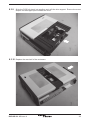
2.1 General description
The BT1050 is a timer for the control of a bottom blowdown valve.
It allows a valve at the bottom of the boiler to open, removing precipitated solids that could
otherwise build up, eventually causing damage.
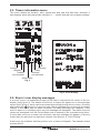
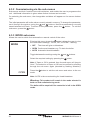
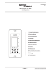
2.2 Front panel
The front panel has an LCD graphics display and five-button keypad:
BT1050
Graphic display
Not used in run mode
Scroll up menus
Scroll down menus
OK
Hold down for 5 seconds
to clear the error screen
Fig. 1 Front panel keypad and definitions
6
IM-P405-39 AB Issue 4
2.3 LCD display
Time
Information line / Date
Timer information
Which timer is to time-out next:
Timer number
Day
Time
Fig. 2 Graphic display
5
Another timer is blowing down
or
Recovery timer:
Indicates the time before
another blowdown can safely
occur, because the blowdown
vessel is still cooling down.
Features only available on
linked BT1000 or BT1050
timers.
Indicates an error or alarm
The display is divided into four main sections:
- Current time.
- Information line / Date.
- Timer information.
- Recovery time.
Operating parameters are selected using a software menu.
2.4 Information line details (in priority order)
Alarm: - 'TEST ALM' - the operator is testing the alarm relay. The relay is either energised (OFF) or
-
de-energised (ON) for 5 minutes. See the commissioning mode TEST-OUTPUT-ALARM
menu.
'ALARM' - an error or fault has occurred. See details in the error screen in run mode and
Section 9, 'Fault finding'.
Bottom blowdown valve (BB):
- 'TEST BB' - the operator is testing the blowdown relay. The relay is either energised (ON)
or de-energised (OFF) for 5 minutes. See the commissioning mode TEST-OUTPUT-VALVE
menu.
- 'MAN OFF' - the timer is switched off. e.g. manual override. The timer will ignore all
pre-recorded times. See the commissioning MODE-OFF menu.
- 'MAN OPEN' - the valve has been opened continuously. e.g. manual override. See the
commissioning MODE-ON menu.
- 'DELAYED' - a blowdown is overdue but cannot occur until the RECOVERY TIMER elapses.
- 'BLOWDOWN' - a timed blowdown is occurring. i.e. the valve is open.
IM-P405-39 AB Issue 4
7
2.5 Timers information menu
This menu details the duration, start, repeat and stop time that has been selected. It
also displays which days have been selected. A ' - ' means that day has not been selected.
Timer 1
duration
5 s
start
08:00
repeat
01:00
stop
16:00
sm-w-fs
Sunday
Saturday
Monday
Friday
Tuesday
Thursday
(not selected)
(not selected)
Wednesday
Fig. 3
PRESS OK
TO CLEAR
Fig. 4 Error display
2.6 Alarm / error display messages
If an error occurs, an exclamation mark (!) will flash in the bottom left corner of the run
display (see Figure 2). The details of the error or alarm will appear on a new message
screen (see Figure 4), which can be accessed by scrolling through the run menu. Pressing
and holding the OK button for 3 seconds can clear a message and re-energize the alarm
relay(s). If the cause has not been corrected, the same message will reappear. If the
error or alarm is of a latching type, only the message will disappear. The alarm relay will
remain de-energised until the correct pass code is entered in the commissioning menu.
If more than one error or alarm has occurred, the next message will appear (in priority
order) after the previous one has been cleared. See Section 9, 'Fault Finding'.
If there are any problems with the product, error or alarm will appear. The example shows
a power failure.
8
IM-P405-39 AB Issue 4
2.7 Other features
A test function provides the operator with a diagnostic tool.
The BT1050 can communicate via an Infrared link between adjacent units. It can be designated
as either a slave or a master unit - see Section 7, 'Communications'.
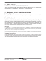
2.8 Equipment delivery, handling and storage
Factory shipment
The product is tested, calibrated and inspected prior to shipment, to ensure reliable
operation.
Receipt of shipment
Each carton should be inspected at the time of delivery for possible external damage. Any
visible damage should be recorded immediately on the carrier's copy of the delivery slip.
Each carton should be unpacked carefully and its contents checked for damage. If it is found
that some items have been damaged or are missing, notify Spirax Sarco immediately and
provide full details. In addition, damage must be reported to the carrier with a request for
their on-site inspection of the damaged item and its shipping carton.
Storage
If the product is to be stored for a period prior to installation, the environmental storage
conditions should be at a temperature between 0°C and 65°C (32°F and 149°F), and between
10% and 90% relative humidity (non-condensing).
Ensure there is no condensation within the unit before installing and connecting the power.
Operator instructions
An alternative operator instruction manual, in place of this manual, for operating the equipment
is required. This will avoid the commissioning menu passcode being disclosed to the operator.
The alarm reset passcode may optionally be disclosed if this is deemed necessary.
IM-P405-39 AB Issue 4
9
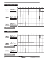
3. System overview
The BT1050 controls the opening and closing of a valve at the bottom of the boiler to
remove precipitated solids that could otherwise build up, eventually causing damage.
Each BT1050 has three timers. Three timer sequences are available. Only one timer
sequence can be allocated to any one day.
The timers are also used to prioritise boiler blowdown cycles. This:
- allows recovery time (for water in a blowdown vessel to cool),
- minimises waste of heat and water,
- selects the most suitable blowdown time (i.e. avoiding peak steam demand times).
Up to nine BT1050 units can be installed and linked for multi-boiler installations, preventing
more than one boiler blowing down at a time. This feature avoids the possibility of overloading
a blowdown vessel, which could lead to water being discharged to drain at too high a
temperature.
Inputs
The timer is connected directly to the mains supply.
Function / output
When a blowdown is due, a relay energises to open the bottom blowdown valve for the
duration selected. After this, the valve closes until the next blowdown cycle.
If the blowdown valve is fitted with a switch box, an alarm relay can be released if the valve fails
to open or to close within a set time (see Commissioning - Section 6.3.9, 'Alarm sub-menu').
Installation A
TIMER 1
sequence
01 02 03 SUN
MON
TUE
WED
THU
FRI
SAT
00 04 05 06 07 08 09 Start time = 8:00
TIMER 3
sequence
SUN
MON
TUE
WED
THU
FRI
SAT
TIMER 2
sequence
SUN
MON
TUE
WED
THU
FRI
SAT
Start time = 00:00
Start time = 8:00
Repeat = 01:00
10
IM-P405-39 AB Issue 4
BT1050 functional timing diagram
(Multi-blowdowns per day)
Setting up the timers - explanation:
1. Three TIMER sequences / patterns available
2. For each day, only one timer sequence can be allocated.
3. Timers 2 and 3 are not available if timer 1 is not being used or all of timer 1 days are
used.
4. Timers 3 is not available if timers 1 and timer 2 use all the days.
Four user variables are available:
DURATION: The time duration of the blowdown
START: The time (HRS, MINS), the timer sequence is to start.
STOP: The time (HRS, MINS), the timer sequence is to stops.
REPEAT time: The time (HRS, MINS) for the next repeated blowdown. If REPEAT = 00:00,
only one blowdown will occur at start.
CLOCK - 24 hrs
10 11 12 13 14 Repeat = 00:00
Duration = 20 seconds
15 16 17 18 19 20 21 22 23 00
Stop time = 17:00
Stop time = 17:00
Repeat = 08:00
Stop time = 17:00
IM-P405-39 AB Issue 4
11
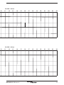
Installation B
TIMER 3
sequence
03 04 05 06 07 08 09 00 01 02 03 04 05 06 07 08 09 SUN
MON
TUE
WED
THU
FRI
SAT
02 SUN
MON
TUE
WED
THU
FRI
SAT
TIMER 2
sequence
01 SUN
MON
TUE
WED
THU
FRI
SAT
TIMER 1
sequence
00 Not available
TIMER 2
sequence
SUN
MON
TUE
WED
THU
FRI
SAT
TIMER 1
sequence
SUN
MON
TUE
WED
THU
FRI
SAT
Installation C
TIMER 3
sequence
SUN
MON
TUE
WED
THU
FRI
SAT
Not available
Not available
12
IM-P405-39 AB Issue 4
CLOCK - 24 hrs
10 11 12 13 14 15 16 17 18 19 20 21 22 23 00
14 15 16 17 18 19 20 21 22 23 00
CLOCK - 24 hrs
10 11 12 13 IM-P405-39 AB Issue 4
13
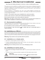
4. Mechanical installation
Note: Read the 'Safety information' in Section 1 before installing the product.
The product must be installed in a suitable industrial control panel or fireproof enclosure
to provide impact and environmental protection. A minimum of IP54 (EN 60529) is
required. If installed in a harsh environment (conductive dust and / or wet conditions),
extra protection is required.
During installation or maintenance, the rear of the product must be protected from
environmental pollutants entering the product. Alternatively, the tasks can be performed
in a dry clean environment.
Caution 1: The product must only be installed in the vertical orientation.
Caution 2: Do not cover or obstruct the infrared beam between products.
Ensure that the display can be easily read by the operator.
Warning: The boiler control panel or enclosure doors must be kept closed at all
times unless installation or maintenance work is being carried out.
4.1 Environmental conditions
Install the product in an environment that minimises the effects of heat, vibration, shock and
electrical interference (see Section 1 - 'Safety information').
Do not install the product outdoors without additional weather protection.
Do not attempt to open the product - it is sealed and has no replaceable parts or
internal switches.
4.2 Installation on a DIN rail
The product is provided with a clip and a set of self-tapping screws to secure it to a 35 mm DIN
rail. On the rear of the enclosure, two sets of holes are provided to give two height positions.
The clip can be adjusted to give further positions. Locate the clip onto one set of holes and
secure it using the two screws provided. Ensure the spring clip is fully engaged with the rail.
Warning: Only use the screws provided with the product.
4.3 Installation on a chassis plate:
- Drill holes in chassis plate as shown in Figure 5.
- Fit unit to chassis plate and secure with 2 screws,
provided at the top and bottom of the case.
nuts and washers, using the slots
Warning: Do not drill the product case or use self-tapping screws.
4.4 Installation in a panel cutout:
(Minimum panel thickness 1 mm if the bezel is used).
- The product has integral threaded inserts (M4 x 0.7) at the top and bottom of the front
panel.
- Two M4 x 25 mm screws are provided, together with fibre washers and a bezel.
Warning:
Do not use screws over 25 mm in length - danger of electric shock.
14
IM-P405-39 AB Issue 4
- Cut the panel to the dimensions given in Figure 5. Drill the screw holes in the panel in the
positions indicated.
- Remove the backing from the gasket supplied and apply to front face of the product.
- The bezel can be used to enhance the appearance of the panel cutout. If required, fit this
to the outside of the panel.
- Fit the unit from the rear of the panel, and secure using the screws, washers (and bezel)
provided.
- Tighten the M4 screws to 1.0 - 1.2 Nm.
WARNING: Do not drill the product case or use self-tapping screws.
Ø 4.2 mm
Ø 4.2 mm
10 mm
15 mm
45 mm
112 mm
92 mm
22.5 mm
22 mm
10 mm
Ø 4.2 mm
Ø 4.2 mm
67 mm
Fig. 5 Chassis plate / panel - cutout diagram
Fixing template cutout notes:
- Solid line indicates cutout required for panel mounting.
- Broken line indicates product outline.
- A minimum gap of 15 mm between units must be provided for product cooling.
- Mounting hole dimensions are the same for both panel and wall mounting.
IM-P405-39 AB Issue 4
15
5. Electrical installation
Note: Before installing read the 'Safety Information' in Section 1.
Warning:
Isolate the mains supply before touching any of the wiring terminals as
these may be wired to hazardous voltages.
Use only the connectors supplied with the product, or spares obtained from
Spirax Sarco Limited. Use of different connectors may compromise product
safety and approvals. Ensure there is no condensation within the unit before
installing and connecting the power.
Connecting the mains supply incorrectly can cause damage and may
compromise safety.
5.1 General wiring notes
Every effort has been made during the design of the product to ensure the safety of the
user but the following precautions must be observed:
1. Maintenance personnel must be suitably qualified to work with equipment having
hazardous live voltages.
2. Ensure correct installation. Safety may be compromised if the installation of the product
is not carried out as specified in this IMI.
3. The design of the product relies on the building installation for overcurrent protection
and primary isolation.
4. Overcurrent protection devices rated at 3 amps must be included in all phase conductors
of the installation wiring. If overcurrent protection is included in both supply wires then the
operation of one must also cause the operation of the other. Refer to IEC 60364 (Electrical
Installations of Buildings) or National or Local standards for full details of requirements
for overcurrent protection.
5. A 3 A quick-blow overcurrent protection device must be fitted to the relay circuit(s).
6. Relay contacts must be supplied on the same phase as the mains supply.
7. The product is designed as an installation category III product.
8. Install wiring in accordance with:
-
IEC 60364 - Low-voltage electrical installations.
-
EN 50156 Electrical Equipment for furnaces and ancillary equipment.
-
BS 6739 - Instrumentation in Process Control Systems: Installation design and practice
or local equivalent.
9. It is important that the cable screens are connected as shown in order to comply with
the electromagnetic compatibility requirements.
10.All external circuits must meet and maintain the requirements of double / reinforced
installation as stated in IEC 60364 or equivalent.
16
IM-P405-39 AB Issue 4
11.Additional protection must be provided to prevent accessible parts (e.g. signal circuits)
from becoming Hazardous Live if a wire or screw is accidentally loosened or freed. Ensure
all wires are secured to at least one other wire from the same circuit. The attachment
must be as close to the terminal block as possible but must not apply undue stress on
the connection. Example: Use a cable tie to secure the live and neutral wire together. If
one wire becomes loose the other wire will prevent it from touching accessible parts.
12.A disconnecting device (switch or circuit breaker) must be included in the building
installation. It must:
- Have a rating with sufficient breaking capacity.
- Be in close proximity to the equipment, within easy reach of the operator, but not fitted
in a position that makes it difficult to operate.
- Disconnect all phase conductors.
- Be marked as the disconnecting device for the product.
- Not interrupt a protective earth conductor.
- Not be incorporated into a mains supply cord.
- Comply with the requirements for a disconnecting device
specified in IEC 60947-1
(Specification for low-voltage switchgear and control gear - General rules) and
IEC 60947-3 (Switches, disconnectors, switch-disconnectors and fuse-combination
units).
13.See Section 10 - 'Technical information' for terminal and cable specification.
IM-P405-39 AB Issue 4
17
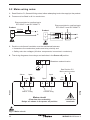
5.2 Mains wiring notes:
1. Read Section 5.1, General Wiring notes, before attempting to wire the supply to the product.
2. Fuses must be fitted in all live conductors.
Disconnect device conforming to
IEC 60947-1 and IEC 60947-3
Product
2
3 A fuse
1
Disconnect device conforming to
IEC 60947-1 and IEC 60947-3
L
Product
N
2
L1
3 A fuses
1
L2
3. Double or reinforced insulation must be maintained between:
- Hazardous live conductors (mains and relay circuits) and
- Safety extra low voltages (All other components/ connectors/ conductors).
4. The wiring diagrams show relays and switches in the Power off position.
N
L
Blowdown solenoid valve
N
See Section 5.2
Mains wiring notes
Input
Alarm
3A
fuse
Norm
8
7
Input
6
3A
fuse
Open
5
4
3
L
N
2
1
3A
fuse
Alarm 1 relay
Control relay
Mains circuit
(View from the underside)
Relays are shown in the power off position
Back
Front
ac supply
Caution live
terminals
Fig. 6 Mains circuit
18
IM-P405-39 AB Issue 4
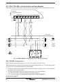
5.3 Signal wiring notes
An earth current loop is created if a wire or screen is connected between two earth points
that are at different potential (voltage). If the wiring diagram is followed correctly, the screen
will only be connected to the earth at one end.
The earth terminal is a functional earth rather than a protective earth.
A protective earth provides protection from electric shock under a single fault condition. This
product has double insulation and therefore does not require a protective earth. A functional
earth is used in order for the product to operate. In this application, the earth is used as a
sink or drain for any electrical interference. The earth terminal must be connected to a local
earth in order to conform to the EMC directive.
Signal circuit
Battery
back-up
switch
Back
Front
(view from the top)
On
Off
COM SCN Tx- Tx+ Rx- Rx+ H / D H / D
E 97 96 95 94 93 92 91 90
Connect to
clean earth
local to the
panel
BB switch
Lockout
75 74 73 72 71 70
Bottom blowdown
switch (shown with valve
closed)
Link to
other bottom
blowdown
timers
Notes:
E = Functional earth - Connect these pins to a clean earth local to the panel.
Switch battery back-up switches ON to activate battery.
Fig. 7 Signal circuit
IM-P405-39 AB Issue 4
19
5.4 EIA / TIA-485 communication wiring diagram
Front
The product can be connected as a slave to a two or four-wire EIA / TIA-485 multi-drop network.
Slave(s)
(Boiler controller)
COM SCN Tx-
E
Tx+ Rx- Rx+ H / D H / D
97 96 95 94 93 92 91 90
Common
R*
R*
B'
A'
R*
R*
B
A
Rx
Earth*
* See
wiring
notes
Tx
Master
Fig. 8 RS485 / Modbus full duplex circuit (view from the top)
EIA / TIA-485 wiring notes:
EIA / TIA-485 symbols are used (A = Tx-, B = Tx+ and A' = Rx-, B' = Rx+).
The signal direction is relative to the product being the Modbus slave, i.e. Tx+ from the product
(slave) is to be connected to the Rx+ of the master.
- Twisted pair cable should not be required for short lengths of cable < 1.5 m (< 5 ft). Standard
screened cable should suffice.
- The H/D (Half duplex) pins are used to select two or four-wire Modbus:
i) For two-wire mode, connect terminal 91 and 90 together.
ii) For four-wire mode, do not connect terminals 91 and 90 together.
Continued on page 17
20
IM-P405-39 AB Issue 4
Front
Slave(s)
(Boiler controller)
COM SCN Tx-
E
Tx+ Rx- Rx+ H / D H / D
97 96 95 94 93 92 91 90
Add link between
terminals 91 and 90
Common
R*
R*
Earth*
* See wiring notes
Rx
Tx
Master
Fig. 9 RS485 / Modbus half duplex circuit (view from the top)
EIA / TIA-485 wiring notes continued:
- The bus common must be connected directly to protective ground / earth at one point only.
Generally this point is at or near the master device.
- Consider
terminating the two furthest ends of the bus to match the transmission line
impedance. A 150 ohm (0.5 W) resistor or a 120 ohm (0.25 W) resistor, which is decoupled
with a 1 nF (10 V) capacitor is commonly used, but ideally the line impedance should be
matched to each individual installation. Termination for short lengths of cable should not
be necessary < 300 m (< 1 000 ft) @ 9 600 Baud.
- See 'Technical information' for cable details.
IM-P405-39 AB Issue 4
21
6. Commissioning
6.1 General information
All commissioning for the product is carried out using the front panel. The front panel consists
of a graphics display and a 5-button keypad - See Figure 10 and Section 2.
Warning: On entering the commissioning mode the product will cease normal control.
The control relay will shut the valve. For safety, the alarm relay will continue to operate
as normal. To regain normal control, return to the run menu.
Warning: If during commissioning, the buttons are not pressed for over 5 minutes, the
controller will revert to run mode and an error will be displayed. If the commissioning
was incomplete the controller may not provide the correct control.
The programmed settings are held in non-volatile memory (Flash) and are written to after
changing a parameter and pressing the OK button. For quick set-up see Section 6.2.
An internal battery is used to keep the clock calendar running when the mains supply
is switched off. To connect the battery, set both of the battery back-up switches (see
Section 5.3), to the on / down position.
Note: If the product has been powered down with the battery switched off, the display will
show a spurious time and date on power up. To correct this, switch on the battery and
enter the correct time and date.
BT1050
Graphic display
Exit sub-menus and shift left
to the next digit when the
parameter or digit is flashing
Scroll up
menus / sub-menus to
Increase digits
Scroll down
menus / sub-menus to
Decrease digits
OK
Enter sub-menus and
shift right to the next digit
when the parameter or
digit is flashing.
Enters parameters when the
parameter or digit is flashing.
Hold down for 5 seconds to
enter commissioning mode.
Fig. 10 Front panel display
22
IM-P405-39 AB Issue 4
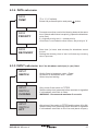
6.1.1 Commissioning mode navigation
After the correct pass code has been entered the display shows:
MODE
To exit the commissioning mode at any stage, press and hold the
button to return to the run mode.
Press the
and
buttons to scroll through the first level menus.
Press the
button to enter a particular sub-menu.
The first menu title will remain displayed at the top of the screen
and the new sub-menu will appear on the next line. As you
progress through the menu, the longer the list becomes. This aids
navigation of the menu structure.
6.1.2 Changing settings (parameters)
If a particular sub-menu requires a parameter to be modified, the corresponding units (if any)
will appear on the next line (in brackets) and the parameter itself will appear on the bottom
right hand corner. The first digit will start flashing and the parameter can be modified.
If the OK button is pressed, the displayed value will be entered into memory. If the
button
is pressed the value remains unchanged. The sub-menu title, parameter and units will
disappear, and the selection on the previous menu will be displayed.
Note: If a number is keyed in that is outside the parameters, an exclamation mark (!) will
appear to the left of the parameter. The minimum or maximum acceptable parameter(s) will
then be displayed.
IM-P405-39 AB Issue 4
23
6.2 Commissioning - Quick set-up
This section allows the user to carry out the minimum commissioning necessary to operate
the system.
It accepts the defaults set in the factory, so will only work if the original default settings have
not been altered - See Section 10.10, 'Default settings' to confirm.
Settings can then be tailored to suit the individual requirements of the customer / application
if required.
Warning
It is essential that you comply with National / Local regulations and Guidance notes,
and the boiler manufacturers' recommendations. It is imperative that the settings
you have accepted will allow the boiler to operate in a safe manner.
Warning
It should be noted that additional cooling capacity must be installed for applications
where frequent blowdown is required.
All BDV60 blowdown vessels are designed with two threaded connections for installing
a Spirax Sarco self-acting cooling system. In the UK and in many other countries the
cooling system should be set to maintain BDV60 water discharge at a temperature
below 43°C
Quick set-up - Commissioning
For a single boiler installation, without a blowdown valve switch fitted, and with a recovery
time of 4 hours.
Parameter
Set to
1. Clock - Hours
- Minutes
Actual time and date
- Month
- Year
Depends on installation and water condition, but 5 seconds
2. Duration of blowdown
is the recommended maximum initially
3. Start time, repeat,
Set the blowdown sequence as required; start time, repeat,
stop time, days
stop time, day
4. Recovery time
4 hours
Test the system to ensure that it is working correctly.
24
IM-P405-39 AB Issue 4
6.3 Commissioning - full
6.3.1 Main menu structure
ä
MODE
ä
DATA
Allows the user to view and change the valve status OFF, OPEN
or AUTO.
Allows displayed units to be configured:Temperature in °C or °F, multiple timer priority and recovery
time to allow blowdown vessel contents to cool.
ä
INPUT
Configures the link to switch box on the bottom blowdown valve.
ä
OUTPUT
Configures the output communications link.
ä
CLOCK
Sets actual year, date and time.
ä
TIMER 1
Allows the user to set up the first blowdown sequence
Duration, Start, Repeat, Stop and Days.
ä
Allows the user to set a second sequence, if required.
For example a different blowdown duration and frequency may
be required over weekends. Not available if, Timer 1 not used or
alldays are used.
TIMER 2
ä
TIMER 3
As Timers 1 and 2 if required.
Not available if Timer 2 not used or all days are used by
Timer 1 or timer 2
ä
ALARM
Warns if the valve does not lift off its seat in a given time.
Set to OFF if the valve is to be opened manually without the alarm
sounding. Latch / non latching option.
ä
TEST
Allows the product display and functions to be tested.
ä
SW. VER
Indicates the software version installed in the product.
ä
SET PASS
IM-P405-39 AB Issue 4
Allows the user to set their own password.
25
6.3.2 Commissioning via the sub-menus
Sub-menus and their functions are outlined below, and enable the user to programme the
unit. Additional information is given where further choices can be made.
On selecting the sub-menu, the changeable variables will appear on the screen bottom
right.
The initial parameter will be the value currently stored in memory. To change the parameter,
scroll through the options using the
and
buttons. Note the parameters currently
saved /selected will flash. To select a new parameter, press the OK button. To exit the
sub-menu, press the
button.
6.3.3 MODE sub-menu
Allows the user to switch from automatic or manual control of the valve.
Entering this menu (press the
button) allows the user to view
the valve status settings, 'AUTO, OFF, or OPEN' - flashing:
MODE
-OFF The timer will give no blowdown.
- OPEN Continuous blowdown e.g. To drain the boiler.
- AUTO Automatic timed blowdown.
Toggle between the settings using the
and
Select the required setting by pressing the
OK
buttons.
button.
Note: If Open or Off is entered, then the sub-menu will jump to
'Auto'. The selection of Open or Off can be verified by scrolling
through the sub menu again (denoted by flashing selection).
OPEN
Press the
mode.
button to exit the sub-menu and return to the run
Note: AUTO is the normal setting for timed blowdown.
Warning: This product will remain in the mode selected in
both run and commissioning mode.
The boiler will be emptied if the controller is left in the OPEN
mode.
26
IM-P405-39 AB Issue 4
6.3.4 DATA sub-menu
ä
DATA
TEMP
°F or °C (°C default).
Select the preferred option and press
OK
button.
ä
DATA
PRIORITY
Prevents more than one boiler blowing down at the same
time. Selects which timer has priority (opens the blowdown
valve first).
9 = highest priority and 1 = lowest priority
If the timer is not linked to other timers, set priority to '0'.
ä
DATA
RECOVERY
6.3.5 INPUT sub-menu
ä
INPUT
SWITCH
Sets time (in hours and minutes) for blowdown vessel
to cool.
Setting the recovery time to 'zero' will clear any recovery
time in process.
Set if the blowdown switch(es) is (are) fitted.
Switch fitted to blowdown valve - Fitted.
No switch on blowdown valve - NONE.
Select required setting.
ä
INPUT
SWITCH
CLOSING
Only shown if the switch is FITTED.
Sets the delay time (seconds) before an alarm is signalled
if a blowdown valve fails to close.
WARNING - Recommend maximum 5 seconds.
ä
INPUT
SWITCH
LIFT
IM-P405-39 AB Issue 4
Only shown if the switch is FITTED and the alarm lift is ON.
Sets the delay time (seconds) before an alarm is signalled
if a blowdown valve fails to lift of its seat (starts to open).
27
6.3.6 OUTPUT sub-menu
Selects MODBUS communication settings:
ä
OUTPUT
COMMS
ADDRESS
Address - This sets the address for Modbus communication.
The default is 001, and the maximum is 247.
ä
OUTPUT
COMMS
BAUD
Baud rate defines the speed of communication between
the product and an interrogating device in bits per second.
The product can be set up to 1200, 9600 or 19200 Baud,
with a default setting of 9600.
ä
OUTPUT
COMMS
IR COMMS
28
IR Comms - Sets Infrared master / slave configuration.
Select SLAVE unless communication is required.
IM-P405-39 AB Issue 4
6.3.7 CLOCK sub-menu
ä
CLOCK
HRS
HRS (24) sets time in hours.
ä
CLOCK
MINS
Sets time in minutes.
ä
CLOCK
YRS
Sets current year (e.g. 09).
ä
CLOCK
MONTH
Sets month (e.g. 05 for May).
ä
CLOCK
DATE
Sets date (1-31).
ä
CLOCK
DAY
Sets actual day of the week.
Note This is not day(s) on which blowdown occurs.
ä
CLOCK
FORMAT
IM-P405-39 AB Issue 4
Sets date / month format.
Select day / month, as UK, Europe, or month / day, as USA.
29
6.3.8 TIMER sub-menu
This timer controls the bottom blowdown times and their duration.
The parameters will vary according to the type of boiler. Seek advice from a boiler
manufacturer, insurance company, or a competent water treatment company. Timers 1, 2,
and 3 are set in exactly the same way - see below:-
ä
TIMER 1, 2 or 3
DURATION
This is the time (in seconds) the blowdown valve is to
open - the actual blowdown period. Seek advice from a
boiler manufacturer, insurance company, or a competent
water treatment company.
We recommend a 5 second duration initially.
ä
TIMER
Start
The time (Hrs, Mins) the blowdown sequence is to start
Note: If start time is greater than stop time,the display
resets to zero.
Only shows if duration is greater than 0 seconds.
ä
TIMER
REPEAT
The time (Hrs, Mins) for the next repeated blowdown. If
REPEAT = 0, only one blowdown will occur at start.
Note: If '12' is entered in hours then minutes only display
'0' (zero).
Only shows if duration is greater than 0 seconds.
ä
TIMER
STOP
The time, (Hrs, Mins) the blowdown sequence is to stop.
Only shows if duration is greater than 0 seconds.
ä
TIMER
DAY
Allows for selection of the day in which the blowdown
sequence is to occur. Advised, 'in use', if the selected
day is already allocated to another blowdown sequence.
Only shows if duration is greater than 0 seconds.
Explanation of setting up of the timers:
1. Three TIMER bolier sequences are available.
2. For each day, only one timer sequence can be allocated.
3. Timer 2 and Timer 3 are not available if Timer 1 is not being used, that is, if no
blowdown is required (duration = 0) or all available days have been selected in Timer 1.
4. Timer 3 is not available if Timer 1 and Timer 2 use all the days.
30
IM-P405-39 AB Issue 4
6.3.9 ALARM sub-menu
ä
ALARM
LIFT
ä
ALARM
LATCH
Only shows if the switch is FITTED. Set ON or OFF.
ON - The alarm will sound if the valve fails to lift within
the time set in INPUT / LIFT.
OFF - No alarm.
Note: If ON selected, alarm will operate if MODE set to
OPEN, or if valve is manually opened.
Only shows if switch is fittted, set On or Off.
ON - Alarm will latch until commissioning mode is entered.
OFF - Alarm will only sound until the alarm condition is
removed.
Note: If switch is fitted, the timer will latch an alarm if the
valve fails to close. This cannot be disarmed.
6.3.10 TEST sub-menu
ä
TEST
DISPLAY
Tests the display:
- (black on white or white on black).
- Allows the user to visually identify faulty pixels on the
display.
ä
TEST
INPUT
Tests inputs:
INT TEMP - Shows maximum internal temperature
of the electronics.
LINK - Detects if other boilers are blowing down. Will
show 'ON' if MODE-OPEN is selected.
SWITCH - Detects if the switch is open or closed.
ä
TEST
OUTPUT
Tests outputs:
VALVE - Opens or closes valve manually.
ALARM - Energises / de-energises alarm relay manually.
CANCEL - Select cancel or wait 5 minutes to return to
automatic control.
IM-P405-39 AB Issue 4
31
6.3.11 SOFTWARE VERSION sub-menu
SW VER
Allows the software version to be viewed. See separate
literature for further information.
6.3.12 PASS CODE sub-menu
SET PASS
32
This allows the default pass code to be changed to a
user-defined value. It is important that if the default
pass code is changed that the new value is noted and
kept safe.
IM-P405-39 AB Issue 4
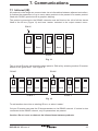
7. Communications
7.1 Infrared (IR)
All products in the range can communicate via an infrared bus between adjacent controllers.
It enables the parameters of up to seven slave products to be passed to a master product
fitted with RS485 (products with a graphics display).
The product connected to the RS485 networks must be fitted on the left of all the slaves
fitted to the IR bus (Figure 11) and have ‘master’ selected in the ‘output-comms’ menu.
RS485
Master
Slave
Slave
Slave
Slave
IR Bus
Fig. 11
Two or more IR buses can share the same panel or DIN rail by selecting another IR master.
Master 2 will ignore bus 1. See Figure 12.
RS485
Master
1
RS485
Slave
Slave
Slave
Slave
Master
2
Slave
IR Bus 1
Slave
Slave
Slave
IR Bus 2
Fig. 12
To add another slave into an existing IR bus, re-select ‘master’.
Only an IR master can pass the IR bus parameters to the RS485 network. If a slave is also
connected to the RS485 network, only its parameters are passed.
Caution: Do not cover or obstruct the Infrared beam between products.
IM-P405-39 AB Issue 4
33
7.2 RS485 addressing
An offset is added to the register addresses (see above) for each device, depending on their
position on the IR bus, i.e. the master’s offset is 0, the device to its right hand side has an
offset of 100, the one to its right 200 and so on.
RS485
Slave
Master
Slave
Slave
Slave
IR Bus
IR address
1
2
3
4
5
RS485 Offset
0
100
200
300
400
Fig. 13
8. Maintenance
Note: Read the 'Safety information' in Section 1 before starting any maintenance.
No special servicing, preventative maintenance or inspection of the product is required.
During installation or maintenance, the rear of the product must be protected from
environmental pollutants entering the product. Alternatively, the tasks can be performed
in a dry clean environment.
8.1 Cleaning instructions
Use a cloth dampened with water or isopropyl alcohol. Use of other cleaning materials could
damage the product and invalidate the marking.
8.2 Bottom blowdown
In many countries, including the UK, legal regulations are in force concerning boiler blowdown.
In particular, attention is drawn to the danger of working on a shut-down boiler while other
boilers are operating.
General guidance is given in Health and Safety Executive Guidance Note PM60.
The battery can be replaced, and must be removed before disposing of the product.
The battery must not be disposed of in waste destined for landfill or untreated incineration, but
must be collected separately and disposed of in accordance with local and national regulations.
34
IM-P405-39 AB Issue 4
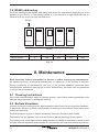
8.3 Replacement and disposal of battery
Caution:- Permanent damage will occur if the printed circuit board (pcb) is completely
removed.
- Do not remove the front keypad.
8.3.1 Cut the two side labels along the join line.
8.3.2 Squeeze enclosure in positions indictated to release locking tabs.
IM-P405-39 AB Issue 4
35
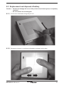
8.3.3 Remove the rear half of the enclosure only.
8.3.4 Remove the blue support.
36
IM-P405-39 AB Issue 4
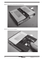
8.3.5 Caution: permanent damage will occur if the printed circuit board (PCB) is completely
removed. Slide the PCB out just far enough to access the cable tie securing
the battery.
Cable tie hole
8.3.6 Cut the cable tie and lift the battery from the PCB.
IM-P405-39 AB Issue 4
37
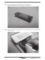
8.3.7 Insert the new battery. See Section 10.5 for the battery type.
Note: the battery is polarised and only fits one way round.
8.3.8 Thread a new cable tie through holes in the PCB, fasten securely around the battery
38
and trim the end.
IM-P405-39 AB Issue 4
8.3.9 Slide the PCB fully back into position and refit the blue support. Ensure the arrow
shapes on the support point toward the front.
8.3.10 Replace the rear half of the enclosure.
IM-P405-39 AB Issue 4
39
9. Fault finding
WARNING:
Before fault finding read the Safety information in Section 1 and the General
wiring notes in Section 5.1.
Please note that there are hazardous voltages present and only suitably
qualified personnel should carry out fault finding.
The product must be isolated from the mains supply before touching any of
the wiring terminals.
Safety may be compromised if the fault finding procedures are not carried out
in line with this manual.
Relay fuses to be replaced by manufacturer or accredited service department.
During installation or maintenance, the rear of the product MUST be protected
from environmental pollutants entering the product. Alternatively, the tasks can
be performed in a dry clean environment.
9.1Introduction
If for any reason a fault occurs on the product, the instructions in this section will allow the
fault to be isolated and corrected. The most likely time for faults to occur is during installation
and commissioning. The most common type of fault is wiring.
9.2 System faults
Symptom
1
Display not
illuminating
40
Action
1. Switch off the mains supply to the product.
2. Check all wiring is correct.
3. Check external fuse(s) are intact. Replace if necessary.
4. Check the mains voltage is within specification.
5. Switch on mains supply.
If symptoms are still present return product for examination.
Consider the likelihood that the product has been damaged from
mains borne surges / spikes. Consider installing an additional
ac power line protector between the product and the mains supply.
The protector needs to be positioned close to the product to gain
full protection.
IM-P405-39 AB Issue 4
Symptom
Action
2
1. Switch off the mains supply to the product.
2. Disconnect all signal wires.
3. Switch the mains supply on: If symptoms are still present, return
the product for examination.
4. Replace each signal wire in turn until the fault occurs.
5. Investigate and rectify any faults in the wiring, external sensors /
transducers and modules associated with that connection.
Display
flashes
on and off
(1 second
approx.)
3
Explanation
The internal power supply is unable to power up. If the voltages
cannot be generated, the power supply switches off for approx.
1 second. The power supply then attempts to power up again. If the
fault is still present, the cycle is repeated until the fault is removed.
This is a safety feature and does not damage the product.
1. Monitor the mains supply and ensure it is continuous and within
the specification limits.
2. Measure the ambient temperature and ensure it is less than
specified.
3. Investigate symptom 2.
Product
powers up
for a period Explanation
A re-settable thermal cut-out device will operate if one or more of
of time
following occurs:
(greater than the
- The power drawn exceeds the specification.
1 minute),
- The input mains voltage is lower than specified.
- The ambient temperature is higher than specified.
then
- The internal power supply will switch off until the product
switches
temperature drops below 65°C. This is a safety feature and does
off
not damage the product.
IM-P405-39 AB Issue 4
41
Operational error messages
Any operational errors that occur will be displayed in the run mode, on the alarms and
errors screen.
Error
message
1
Power out
2
Valve failed
to open
3
Valve failed
to close
4-6
Data timer X
invalid
7
Data state MC
overflow
42
Cause
Action
There has been a
loss of power to
the product during
operation.
1. Remove the power from the product.
2. Check that all the wiring is correct.
3. Check that the power supply is secure,
i.e. does not suffer from 'brown outs'.
4. Reapply power.
5. Press the OK button to clear.
Blowdown valve
fails to start to
open.
1. Check the correct open time has been
entered in the INPUT-SWITCH-LIFT
menu.
2. Check BB valve switch in the test menu.
3. Check the wiring between switch and the
product.
4. Check the operation of the switch.
5. Check the operation of the valve.
6. Check and replace the switch and/or
valve if necessary.
7. Press the OK button to clear.
Blowdown valve
fails to close fully.
1. Check the correct closing time has
been entered in the INPUT-SWITCHCLOSING menu.
2. See 'Valve failed to open'.
3. Enter the commissioning mode and enter
the correct pass code.
Data in one of
the three timers
has been lost or
corrupted.
Values have
been restored
(X = 1 to 3).
1. Product needs to be re-commissioned.
2. Ensure product or its wiring is not located
near a source of electrical interference.
3. Return product if symptoms persist.
4. Press the OK button to clear.
State machine is
outside its limits.
Values have been
restored.
1. See 'Data timer' X 'Invalid' action.
2. Press the OK button to clear.
IM-P405-39 AB Issue 4
Error
message
Cause
Action
Data in the
recovery counter
has been
corrupted.
1. See 'Data timer X 'Invalid' action.
2. Press the OK button to clear.
9
Data in the timer
flag register
has been lost
or corrupted.
Values have been
restored.
1. See 'Data timer X 'Invalid' action.
2. Press the OK button to clear.
10
Data in the error
flag register
has been lost
or corrupted.
Values have been
restored.
1. See 'Data timer X Invalid' action.
2. Press the OK button to clear.
11
The operator
has entered the
commissioning
mode and has not
pressed a button
for 5 minutes or
more.
1. Re-enter the commissioning mode if
required.
2. Press the OK button to clear.
12
Some errors latch
the alarm relay for
safety. Clearing
the error from
the error screen
just removes the
message.
1. Enter the commissioning (set-up) mode.
If the correct password is entered all the
latched alarms will be cleared.
8
Data recovery
invalid
Data flags
invalid
Data errors
invalid
Setup menu
time out
Alarm is
latched
IM-P405-39 AB Issue 4
43
10. Technical information
10.1 For technical assistance
Contact your local Spirax Sarco representative. Details can be found on order / delivery
documentation or on our web site: www.spiraxsarco.com
10.2 Returning faulty equipment
Please return all items to your local Spirax Sarco representative. Please ensure all items
are suitably packed for transit (preferably in the original cartons).
Please provide the following information with any equipment being returned:
1. Your name, company name, address and telephone number, order number and invoice
and return delivery address.
2. Description and serial number of equipment being returned.
3. Full description of the fault or repair required.
4. If the equipment is being returned under warranty, please indicate:
- Date of purchase.
- Original order number.
10.3 Power supply
Mains voltage range 110 Vac to 240 Vac at 50 / 60 Hz
Power consumption 230 V / 30 mA or 115 V / 60 mA
10.4Environmental
General Indoor use only
Maximum altitude 2 000 m (6 562 ft) above sea level
Ambient temperature limits 0 - 55°C (32 - 131°F)
80% up to 31°C (88°F) decreasing
Maximum relative humidity
linearly to 50% at 40°C (104°F)
Overvoltage category III
2 (as supplied)
Pollution degree
3 (when installed in an enclosure) - Minimum of IP54
Enclosure rating (front panel only)IP65 (verified by TRAC Global)
Torque rating for panel screws
1 - 1.2 Nm
LVD (safety) Electrical safety EN 61010-1
EMC
Immunity / Emissions Suitable for heavy industrial locations
Colour Light grey (similar to RAL7035)
Enclosure
Material
ABS polycarbonate plastic
Colour Pantone 294 (blue)
Front panel
Material Silicone rubber, 60 shore.
Solder Tin / lead (60 / 40%)
44
IM-P405-39 AB Issue 4
10.5 Battery (Clock calendar)
ManufacturerTADIRAN
Manufacturers part number
SL-360 / PT
Spirax Sarco part number
0965057
AA (PCB tagged) Lithium Thionyl Chloride
Type
(Lithium content 0.65 g)
Voltage
3.6 V
Capacity
2.4 Ah minimum
Temperature range
0 - 70°C minimum
Shelf life 10 years - With battery switch OFF @ Tamb: 25°C
Working life 10 years - Mains power on 35 hours / week @ Tamb: 55°C
10.6 Cable / wire and connector data
Mains and signal connector
Rising clamp plug-in terminal blocks with screwed Termination connectors
Cable size
0.2 mm² (24 AWG) to 2.5 mm² (14 AWG).
Stripping length 5 - 6 mm
Please note: Use only the connectors supplied by Spirax-Sarco Limited – Otherwise Safety
and Approvals may be compromised.
Switch box and Lockout (link) circuit
Type Shield type
Number of cores
Gauge
Maximum length Recommended type
High temperature
Screened
2
1 - 1.5 mm² (18 - 16 AWG)
100 m (328 ft)
Prysmian (Pirelli) FP200, Delta Crompton Firetuf OHLS
RS485 communication cable / wire
Type
Shield type
Number of pairs
Gauge
Maximum length Recommended type
EIA RS485 Twisted pair
Screened
2 or 3
0.23 mm² (24 AWG)
1 200 m (4 0 00 ft)
Alpha wire 6413 or 6414
LAN Category 5 or Category 5E ScTP (screened), FTP (foil) or STP (shielded) cable can be
used, but limited to 600 m.
IM-P405-39 AB Issue 4
45
10.7 Input technical data
Switch box
Maximum voltage Maximum current
32 Vdc (no load, open circuit)
3 mAdc (short circuit)
Lockout (link)
Maximum voltage
Maximum pulldown voltage
Maximum current 32 Vdc (no load, open circuit)
0.25 Vdc
1.5 mAdc
10.8 Output technical data
Relay(s)
Contacts Voltage ratings (maximum)
Resistive load
Inductive load
ac motor load
Pilot duty load
Electrical life (operations)
Mechanical life (operations)
2 x single pole changeover relays (SPCO)
250 Vac
3 amp @ 250 Vac
1 amp @ 250 Vac
¼ HP (2.9 amp) @ 250 Vac
1
/10 HP (3 amp) @ 120 Vac
C300 (2.5 amp) - control circuit/coils
3 x 10 5 or greater depending on load
30 x 10 6
RS485
Physical layer Protocol Isolation Receiver unit load Output rate RS485 4-wire full or 2-wire half duplex
Modbus RTU format
60 Vac/dc
(256 devices - maximum)
Up to 10 frames / second
10.9Infrared
Physical layer IrDA
Baud38400
Range
10 cm
Working angle
15°
Exempt from EN 60825-12: 2007 Safety of laser Eye safety information
products- does not exceed the accessible emission limits (AEL) of class 1
46
IM-P405-39 AB Issue 4
10.10Default settings
10.10.1MODE MENU
Allows the valve to be manually opened or closed, automatically opened and closed
under the control of the timer
Ranges
AUTO, OPEN, OFF
DefaultAUTO
10.10.2DATA MENU
TEMP (temperature units)
Ranges
Default
°C or °F
°C
PRIORITY
Ranges Default
Resolution (steps)
0 - 9 (Highest priority)
0 (Timer not linked)
1
10.10.3RECOVERY (flash vessel cooling time - after previous blowdown)
HRS - HOURS
Ranges 00 - 11
Default4
Resolution (steps)
1
Units
Hours (HRS)
MINS - MINUTES
Ranges 00 - 59
Default00
Resolution (steps)
1
Units
Minutes (MIN)
10.10.4INPUT MENU
SWITCH (if a switch is fitted to the valve, select fitted)
Ranges
FITTED or NONE
DefaultNONE
CLOSING (time allowed for valve to close) - Only available if a switch is fitted
Ranges0 - 10
Default5
Resolution (steps)
1
UnitsSeconds
LIFT (time allowed for valve to lift of the seat) - Only available if a switch is fitted
Ranges
0 - 10
Default5
Resolution (steps)
1
UnitsSeconds
IM-P405-39 AB Issue 4
47
10.10.5OUTPUT MENU
COMMS - ADDRESS (MODBUS communication)
Ranges
1 - 247
Default1
Resolution (steps)
1
COMMS - BAUD (MODBUS communication)
Ranges
1200, 9600, 19200
Default9600
COMMS - IR (Infrared communication)
Ranges
MASTER or SLAVE
DefaultSLAVE
COMMS - IR (units in network)
Ranges
1-8
10.10.6CLOCK MENU
HRS - HOURS ~ 24 hour format (clock calendar)
Ranges
00 - 23
Default00
Resolution (steps)
1
Units
Hours (HRS)
MINS - MINUTES
Ranges
00 - 59
Default00
Resolution (steps)
1
Units
Minutes (MINS)
YRS - YEARS
Ranges
00 - 99 (2000 - 2099)
Default00
Resolution (steps)
1
Units
Years (YRS)
MONTH
Ranges
01 - 12
Default01
Resolution (steps)
1
DATE
Ranges
01 - 31
Default01
Resolution (steps)
1
DAY
Ranges
MON, TUE, WED, THU, FRI, SAT, SUN
DefaultSUN
FORMAT
Ranges
Default
48
D / m or m / d
D / m
IM-P405-39 AB Issue 4
10.10.7TIMER X (1 - 3) MENU
DURATION (valve open time)
Ranges0 - 999
Default0
Resolution (steps)
1
UnitsSeconds
Note: If the mains power supply drops below the required specification, or power down
occurs during a blowdown, the relays will de-energize and close the valve. If the mains
supply is restored after the blowdown time has elapsed, the valve will remain shut until the
next scheduled blowdown time.
START HRS : MINS
Start of blowdown sequence Only available if the duration is greater than 0 seconds
Ranges
00:00 - 23:58
Default00:00
Resolution (steps)
1
Note: Start time must be less than STOP time
REPEAT HRS : MINS
Period when blowdown is repeated. Only available if the duration is greater than 0 seconds
Ranges
00:00 or 00:30 - 12:00
Default
00:00 (no repeats)
Resolution (steps)
1
Note: The time for the next repeated blowdown. If repeat =00:00,only one blowdown will
occur at start
STOP HRS : MINS
Stop of blowdown sequence. Only available if the duration is greater than 0 seconds
Ranges
00:01 - 23:59
Default23:59
Resolution (steps)
1
Note: The time (Hrs,Mins) the timer sequence is to stop.
DAYS
(Days blowdown occurs).
Ranges
Default
IM-P405-39 AB Issue 4
Only available if the duration is greater than 0 seconds
SUN MON TUE WED THU FRI or SAT
- (None selected)
49
10.10.8ALARM MENU
LIFT (alarms occurs if the valve does not lift of the seat within lift time)
Only available if the switch is fitted and selected
Ranges
ON or OFF
DefaultON
LATCH (alarm relay can be latched until commissioning mode is entered)
Only available if the switch is fitted and selected
Ranges
ON or OFF
DefaultOFF
10.10.9 TEST MENU
DISPLAY
Ranges
Black-on-white or white-on-black
DefaultBlack-on-white
INPUT - INT TEMP
(Maximum internal temperature of the electronics)
Ranges-40 to +85°C or -40 to +185°F
Resolution (steps)
1
Units
°C or °F
INPUT - LINK
(detects if other boilers are blowing down) Ranges
ON or OFF INPUT - SWITCH
(detects if the switch is open or closed) Only available if the switch is selected
Ranges
OPEN or CLOSED
OUTPUT - VALVE
(opens or closes valve manually) Ranges
ON or OFF
DefaultON
Press the OK button to activate relay - Automatic control of relays is selected by selecting
cancel or after 5 minutes has elapses.
OUTPUT - ALARM (De-energises or energises the alarm relay manually)
Ranges
ON or OFF
DefaultON
Press the OK button to activate relay - Automatic control of relays is selected by selecting
cancel or after 5 minutes has elapsed.
10.10.10 SET PASS MENU (Set pass code)
Ranges0000 - 9999
Default
See Section 2
Resolution (steps)
1
50
IM-P405-39 AB Issue 4
11. Appendix Summary of the Modbus protocol
Format: Byte
Start Data
Parity
Stop
1 bit
8 bit
0 bit
1 bit
Format: Request frame
Address Function code Start address Quantity of registers Cyclic redundancy check (CRC) Total 1 byte
1 byte
2 bytes
2 bytes
2 bytes
8 bytes
Format: Response frame
Address 1 byte
Function code 1 byte (or error code, see below)
Byte count 1 byte (or exception code, see below)
Register data 2 times the quantity of 16-bit register
Error check (CRC) 2 bytes
Total 7 bytes if correct (or 5 bytes if in error)
Only Function Code 03, 'Read holding registers' is allowed.
IM-P405-39 AB Issue 4
51
Parameters and register data
RegisterParameters
6 - Identity
Note: When the device is an IR slave and there is a
temporary error in the IR Master-Slave comms, an offset
of +32768 is added to the identification value of that
particular slave stored in the master's database.
Timer 1 data (days)
Timer 1 start (time)
Timer 1 duration (seconds)
Timer 2 data (days)
Timer 2 start (time)
Timer 2 duration (seconds)
Timer 3 data (days)
Timer 3 start (time)
Timer 3 duration (seconds)
0
1
2
3
4
5
6
7
8
9
The format of the register data is 16 bit integer, with the most significant byte transmitted first.
TIMER 1, 2 or 3 DATA Days
The following is a description of the bit field of the day register. If the bit is equal to '1', that
day has been selected. If equal to zero then the day has not been allocated. 'X' means it has
not been used.
X
SAT
BIT 7
FRI
THU
WED
TUES
MON
SUN
BIT 0
Exception codes
01 illegal function
02 illegal data address
Parameter
Byte 1
Byte 2
Byte 3
Byte 4
Byte 5
Device Function Exception CRC
CRC
AddressCode Code (LSB) (MSB)
Illegal function
XX 83 01 XXXX
Illegal data addressXX 83 02 XX XX
52
IM-P405-39 AB Issue 4
IM-P405-39 AB Issue 4
8888
Only visible if an
error or alarm has
occured
Not visible if the
switch is not fitted
Not visible if the
duration = 0
53
Timer 1 is being used and has some spare slots.
However, if timer 2 is not used or has filled up the
remaining slots.
Do not show timer 3.
Timer 1 not used (no duration or no days selected).
Do not show either timer 2 or 3.
The tinted zone indicates
a feature that is not always
shown.
(ERROR)
LIFT/SEC
CLOSING/SEC
RECOVERY/HRS
PRIORITY
TIMER 3
TIMER 2
TIMER 1
TIME: DATE/<STATUS>
PASSCODE
Run mode
9600
SLAVE
BAUD
IR COMMS
00
01
01
YRS
MONTH
DATE
XX
MINS
OPEN
SWITCH
7452
SET PASS
CANCEL?
ALARM
New format
X.X.X.X.
OFF
ON
OFF
ON
Visible if the switch is fitted
ON
LINK
°C or °F
70
SW. VER
(MINS)
(HRS)
(MINS)
(HRS)
Visible if the same
day is already used
by the other two
timers.
Visible if the same
day is NOT used
by the other timers.
Invisible if the duration = 0
(MINS)
(HRS)
(SEC)
MON
TUE
WED
THU
FRI
SAT
SUN
(MINS)
00
04
(HRS)
Visible if the switch is fitted.
If the switch is ON, the alarm
sounds if the valve is manually
opened.
If the switch is OFF, the valve can be
opened and closed manually without
an alarm occuring.
INT TEMP
OFF
ON
OFF
ON
VALVE
INPUT
DISPLAY
LATCH
LIFT
IN USE
OFF
ON
XX
HRS
XX
MINS
Invisible if the duration = 0
SAT
FRI
THU
WED
TUE
MON
SUN
STOP
XX
HRS
XX
MINS
REPEAT
XX
HRS
START
M/D
000
FORMAT
D/M
00
MINS
DAY
00
HRS (24)
MASTER
001
Visible if the
SWITCH is fitted
MINS
ADDRESS
5
(SEC)
5
(SEC)
FITTED
NONE
HRS
-To exit the sub-menus use the
' ' or ' OK ' buttons.
-The ' ' and ' ' buttons allow
the operator to scroll up and
down through the menu map
when commissioning the unit.
Notes:
DURATION
COMMS
LIFT
CLOSING
SWITCH
RECOVERY
0
°F
°C
OUTPUT
TEST
ALARM
TIMER 3
TIMER 2
TIMER 1
CLOCK
OUTPUT
INPUT
TEMP
DATA
PRIORITY
AUTO
MODE
OFF
OPEN
Commissioning mode
12. Menu map
54
IM-P405-39 AB Issue 4
IM-P405-39 AB Issue 4
55
56
IM-P405-39 AB Issue 4