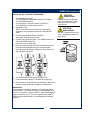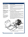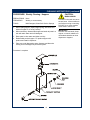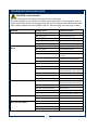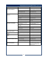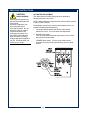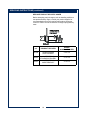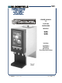
1
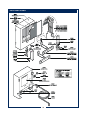
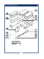
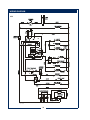
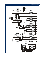
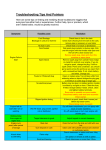
721
OWNERS MANUAL
for
POST-MIX
DISPENSERS
MODELS:
9454
9456
Includes:
Installation
Operation
Use & Care
Servicing Instructions
Model 9456
3-Flavor
Dispenser
p/n 83188 Rev. C ECN- 12738
M721
040811 cps
WARRANTY STATEMENT
It also does not apply if the serial nameplate has been
removed or unauthorized service personnel perform service.
The prices charged by Bloomfield Industries for its products
are based upon the limitations in this warranty. Seller’s
obligation under this warranty is limited to the repair of defects
without charge by a Bloomfield Industries Authorized Service
Agency or one of its sub-agencies. This service will be
provided on customer’s premises for non-portable models.
Portable models (a device with a cord and plug) must be
taken or shipped to the closest Authorized Service Agency,
transportation charges prepaid, for services.
All electrical equipment manufactured by BLOOMFIELD
INDUSTRIES is warranted against defects in materials and
workmanship for a period of one year from the date of original
installation or eighteen (18) months from the date of shipment
from our factory, whichever comes first, and is for the benefit
of the original purchaser, except that:
a. airpots carry a 30 day parts warranty only.
b. dispensers; i.e., tea and coffee carry a 90 days parts
warranty only, excludes decanters.
THE FOREGOING OBLIGATION IS EXPRESSLY GIVEN IN
LIEU OF ANY OTHER WARRANTIES, EXPRESSED OR
IMPLIED, INCLUDING ANY IMPLIED WARRANTY OF
MERCHANTABILITY OR FITNESS FOR A PARTICULAR
PURPOSE, WHICH ARE HEREBY EXCLUDED.
In addition to restrictions contained in this warranty, specific
limitations are shown below (Additional Warranty Exclusions).
Bloomfield Industries Authorized Service Agencies are located
in principal cities.
BLOOMFIELD INDUSTRIES DIVISION / SPECIALTY
EQUIPMENT MANUFACTURING CORPORATION SHALL
NOT BE LIABLE FOR INDIRECT, INCIDENTAL OR
CONSEQUENTIAL DAMAGES OR LOSSES FROM ANY
CAUSE WHATSOEVER.
This warranty is valid in the United States and void elsewhere.
Please consult your classified telephone directory or your food
service equipment dealer; or, for information and other details
concerning warranty, write to:
Service Parts Department
Bloomfield Industries
P.O. Box 280
Verdi, NV 89439
Phone: (775) 689-5700
Fax: (888) 492-2783
This warranty is void if it is determined that upon inspection by
an Authorized Service Agency that the equipment has been
modified, misused, misapplied, improperly installed, or
damaged in transit or by fire, flood or act of God.
SERVICE POLICY AND PROCEDURE GUIDE
ADDITIONAL WARRANTY EXCLUSIONS
1.
2.
3.
4.
5.
6.
7. Full use, care and maintenance instructions are supplied
with each machine. Those miscellaneous adjustments
noted are customer responsibility. Proper attention will
prolong the life of the machine.
8. Travel mileage is limited to sixty (60) miles from an
authorized Service Agency or one of its sub-agencies.
9. All labor shall be performed during normal working hours.
Overtime premium shall be charged to the customer.
10. All genuine Bloomfield replacement parts are warranted
for ninety (90) days from date of purchase on nonwarranted equipment.
Any use of non-genuine
Bloomfield parts completely voids any warranty.
11. Installation, labor and job check-out are not considered
warranty.
12. Charges incurred by delays, waiting time or operating
restrictions that hinder the service technicians ability
to perform services are not covered by warranty.
This includes institutional and correctional facilities.
Resetting of safety thermostats, circuit breakers,
overload protectors, or fuse replacements unless
warranted conditions are the cause.
All problems due to operation at voltages other than
specified on equipment nameplates; conversion to
correct voltage must be the customer’s responsibility.
All problems due to electrical connections not made in
accordance with electrical code requirements and
wiring diagrams supplied with the equipment.
Replacement of items subject to normal wear, to include
such items as knobs and light bulbs. Normal maintenance
functions including adjustment of thermostats, microswitches,
and replacement of fuses and indicating lights are not
covered under warranty.
All problems due to inadequate water supply, such as
fluctuating, or high or low water pressure.
All problems due to mineral/calcium deposits, or
contamination from chlorides/chlorines. De-liming is
considered a preventative maintenance function and is
not covered by warranty.
SHIPPING DAMAGE CLAIMS PROCEDURE
NOTE: For your protection, please note that equipment in
this shipment was carefully inspected and packaged by
skilled personnel before leaving the factory.
Upon acceptance of this shipment, the transportation
company assumes full responsibility for its safe delivery.
IF SHIPMENT ARRIVES DAMAGED:
1. VISIBLE LOSS OR DAMAGE: Be certain that any
visible loss or damage is noted on the freight bill
or express receipt, and that the note of loss or damage
is signed by the delivery person.
2. FILE CLAIM FOR DAMAGE IMMEDIATELY:
Regardless of the extent of the damage.
3.
CONCEALED LOSS OR DAMAGE: if damage is
unnoticed until the merchandise is unpacked, notify the
transportation company or carrier immediately, and file
“CONCEALED DAMAGE” claim with them. This
must be done within fifteen (15) days from the date the
delivery was made to you. Be sure to retain the
container for inspection.
Bloomfield Industries cannot assume liability for damage or
loss incurred in transit. We will, however, at your request,
supply you with the necessary documents to support your
claim.
xi
TABLE OF CONTENTS
WARRANTY STATEMENT
SPECIFICATIONS
FEATURES & OPERATING CONTROLS
PRECAUTIONS & GENERAL INFORMATION
AGENCY LISTING INFORMATION
INSTALLATION INSTRUCTIONS
OPERATION
CLEANING INSTRUCTIONS
TROUBLESHOOTING SUGGESTIONS
SERVICING INSTRUCTIONS
Deliming Instructions
EXPLODED VIEWS
SERVICE PARTS LIST
WIRING DIAGRAMS
xi
1
2
5
5
6
8
11
14
16
19
20
25
26
Thank You for purchasing this
Bloomfield Industries appliance.
Proper installation, professional
operation and consistent
maintenance of this appliance will
ensure that it gives you the very
best performance and a long,
economical service life.
This manual contains the
information needed to properly
install this appliance, and to use,
care for and maintain or repair the
appliance in a manner which will
ensure its optimum performance.
SPECIFICATIONS
MODEL
STYLE
9454
2-FLAVOR
9456
3-FLAVOR
VOLTS
WATTS
AMPS
1ø
POWER SUPPLY
CORD
120 VAC 1ø
1500W
12.5A
NEMA 5-15P
PLUMBING: ¼" O.D. flared flexible tubing tapped from a ¼" or larger potable cold water supply
DIMENSIONS: 9¾" wide x 22½" deep x 26¾" high
SHIPPING WEIGHT:
Model 9454 - 51 pounds
Model 9456 - 65 pounds
APPLICABILITY
This manual applies to the following Bloomfield Industries products:
Café Elite™ Models 9454 and 9456
1
FEATURES AND OPERATING CONTROLS
2
FEATURES AND OPERATING CONTROLS (continued)
ITEM DESCRIPTION
COMMENTS
1
WATER TANK
2
WATER LEVEL PROBES
SENSE HIGH AND LOW WATER LEVELS
3
DISPENSER WATER SUPPLY
TUBES
9456 SHOWN. FOR 9454, CENTER TUBE IS BLANKED
4
WATER TANK FILL TUBE
5
VENT / OVERFLOW
6
HEATING ELEMENT
1500 WATT ELEMENT TO HEAT WATER IN TANK
7
DRAIN FITTING
DRAIN WATER TANK
8
WATER TANK COVER
SHOWN OPEN
9
DOOR / ILLUMINATED
DISPLAY
SHOWN OPEN - DOOR ASSY FOR 9454 & 9456 DIFFER
10
PRODUCT HOPPER
HOPPER ASSY FOR 9454 & 9456 DIFFER
11
HEATER CONTROL SWITCH
"ON" TO DISPENSE HOT BEVERAGE
12
DISPENSE TEMP MODE
SELECT SWITCH
ALLOWS LEFT DISPENSER TO DISPENSE COLD
BEVERAGE
13
WATERLINE / PORTABLE
SELECT SWITCH
SWITCH TO "PORTABLE" WHEN NOT CONNECTED TO
WATER SUPPLY
14
KEYPAD
KEYPAD FOR 9454 & 9456 DIFFER
15
POWER SWITCH
LOCATION OF SWITCH FOR 9454 & 9456 DIFFER
16
BLENDER ASSEMBLY
QTY OF BLENDERS FOR 9454 & 9456 DIFFER
17
DISPENSE / FLUSH SWITCH
"FLUSH" TO CLEAN DISPENSER
18
TANK FILL INDICATOR
USED DURING PORTABLE OPERATION ONLY
19
DRIP TRAY ASSEMBLY
REMOVABLE FOR EASY CLEANING
20
AUGER DRIVE PIN
QTY OF DRIVES FOR 9454 & 9456 DIFFER
21
VACUUM PORT
QTY OF PORTRS FOR 9454 & 9456 DIFFER
22
DISPENSE WATER OUTLET
QTY OF OUTLETS FOR 9454 & 9456 DIFFER
23
RICH / LEAN ADJUSTMENT
QTY OF ADJUSTMENTS FOR 9454 & 9456 DIFFER
WHIPPER BLADES
SHOWN WITH BLENDER HOUSING REMOVED
QTY OF BLENDERS FOR 9454 & 9456 DIFFER
25
DATA PLATE
MAKE/MODEL/SER.NO., VOLTS/AMPS INFORMATION
26
WATER SUPPLY
CONNECTION
WHEN USED IN WATERLINE MODE
27
POWER CORD
120VAC, NEMA 5-15P
24
3
FEATURES AND OPERATING CONTROLS (continued)
INTERNAL COMPONENTS
ITEM DESCRIPTION
COMMENTS
30
WHIPPER MOTORS
31
AUGER MOTOR
32
VENT "TEE"
33
DISPENSE SOLENOIDS
34
TEMPERATURE CONTROL
THERMOSTAT
CONTROLS HEATING ELEMENT
35
HI-LIMIT THERMOSTAT
OVER-TEMP PROTECTION
36
WATER FILL SOLENOID
SUPPLIES WATER TANK
37
COLD WATER "TEE"
COLD BEVERAGE, LEFT DISPENSER ONLY
38
TRANSFORMER
FOR FRONT DOOR LIGHTING
39
VACUUM BLOWER & MOTOR
9454 HAS TWO TUBES ONLY
40
DRAIN LINE FITTING
DRAIN EWATER TANK
41
COLD BEV WATER SOLENOID
AUX WATER SUPPLY IN COLD/HOT MODE
42
CIRCUIT BOARD
CONTROLS WATER LEVEL, DISPENSE SYSTEMS
9454 QTY=2, 9456 QTY= 3
4
PRECAUTIONS AND GENERAL INFORMATION
WARNING: ELECTRIC SHOCK HAZARD
All servicing requiring access to non-insulated components must be performed by qualified
service personnel. Do not open any access panels which require the use of tools.
Failure to heed this warning can result in electrical shock.
WARNING: INJURY HAZARD
All installation procedures must be performed by qualified personnel with full knowledge of all
applicable electrical and plumbing codes. Failure could result in property damage and
personal injury.
WARNING: ELECTRIC SHOCK HAZARD
Dispenser must be properly grounded to prevent possible shock hazard. DO NOT assume a
plumbing line will provide such a ground. Electrical shock can cause death or serious Injury.
WARNING: BURN HAZARD
This appliance dispenses very hot liquid. Serious bodily injury from scalding can occur from
contact with dispensed liquids.
This appliance is intended for commercial use only.
CAUTION:
This appliance is intended for use to dispense beverage
products for human consumption. No other use is
recommended or authorized by the manufacturer or its agents.
ELECTRICAL DAMAGE
This appliance is intended for use in commercial establishments,
where all operators are familiar with the appliance use,
limitations and associated hazards. Operating instructions and
warnings must be read and understood by all operators and
users.
Except as noted, this piece of equipment is made in the USA
and has American sizes on hardware. All metric conversions
are approximate and can vary in size.
Trouble shooting guides, component views and parts lists are
included for general reference, and are intended for use by
qualified service personnel.
DO NOT plug in or energize this
appliance until all Installation
Instructions are read and followed.
Damage to the Brewer will occur if
these instructions are not followed.
CAUTION:
BURN HAZARD
Exposed surfaces of the
appliance and any associated
beverage container may be HOT
to the touch, and can cause
serious burns.
This manual should be considered a permanent part of this
appliance. The manual must remain with the appliance if it is
sold or moved to another location.
AGENCY LISTING INFORMATION
This dispenser is
listed under UL file E9253.
This dispenser is
listed under CSA file LR21315-65.
This brewer meets
Standard 18 only when installed,
operated and maintained in accordance with the enclosed
instructions.
5
INSTALLATION
READ THIS CAREFULLY BEFORE STARTING THE INSTALLATION
IMPORTANT:
To enable the installer to make
a quality installation and to
minimize installation time, the
following suggestions and tests
should be done before the
actual unit installation is started:
CAUTION:
ELECTRICAL
DAMAGE
DO NOT plug in or energize this
appliance until all Installation
Instructions are read and
followed. Damage to the
Brewer will occur if these
instructions are not followed.
Unpack the unit. Inspect all components for completeness and
condition. Ensure that all packing materials have been removed
from the unit.
Read all instructions in this manual carefully before starting
installation of this fryer. READ AND UNDERSTAND ALL
LABELS AND DIAGRAMS ATTACHED TO THE DISPENSER.
Carefully account for all components and accessories before
discarding packing materials:
1 ea. LID ASSEMBLY
1 ea. DRIP TRAY ASSEMBLY
1 ea. HOPPER MOUNTING TRAY
2 ea. HOPPER ASSEMBLY (9454) or
3 ea. HOPPER ASSEMBLY (9456)
1 ea. PRODUCT LABEL SHEET
1 ea. LITERATURE PACKAGE
Store these components in a convenient place for later use:
LEVELING THE UNIT
IMPORTANT: This equipment
must be installed to comply with
applicable federal, state and
local plumbing codes and
ordinances.
NOTE: Water supply inlet line
must meet certain minimum
criteria to insure successful
operation of the brewer.
Bloomfield recommends 1/4"
copper tubing for installation of
less than 12 feet and 3/8" for
more than 12 feet from a 1/2"
water supply line.
Set dispenser in its operating location. Level the dispenser.
A spirit level should be placed on the top of the unit, at the edge,
as a guide when making level adjustments.
PLUMBER’S INSTALLATION INSTRUCTIONS
Brewer must be connected to a POTABLE WATER, COLD
WATER line. Flush water line before connecting to Brewer.
DO NOT use a saddle valve with a self-piercing tap for the water
line connection. Such a tap can become restricted by waterline
debris. For systems that must use a saddle tap, shut off the main
water supply and drill a 3/16” (minimum) tap for the saddle
connection, in order to insure an ample water supply. Remember
to flush the line prior to installing the saddle.
The brewer must be installed on a water line with average
pressure between 20 PSI and 90 PSI. If your water pressure
exceeds 90 PSI at anytime, a pressure regulator must be
installed in the water supply line to limit the pressure to not more
than 90 PSI in order to avoid damage to lines and solenoid.
A water shut-off valve should be installed on the incoming water
line in a convenient location (Use a low restriction type valve,
such as a 1/4-turn ball valve, to avoid loss of water flow thru the
valve.
A water line strainer (not provided; ¼" flare "y" strainer available
separately as p/n SA9052) must be installed in the supply line,
between the shutoff valve and inlet fitting. Note FLOW arrow
marking on strainer body.
6
INSTALLATION (continued)
NSF requires that the brewer be able to be moved for cleaning
underneath. A flex line or loops of copper tubing will satisfy this
requirement. See Figure 2 below.
WARNING:
SHOCK HAZARD
Brewer must be properly
grounded to prevent possible
shock hazard. DO NOT
assume a plumbing line will
provide such a ground.
Electrical shock will cause death
or serious injury.
IMPORTANT:
Supply power must match
nameplate for voltage and
phase. Connecting to the
wrong voltage will damage the
brewer or result in decreased
performance. Such damage is
not covered by warranty.
Fig. 2 Water Supply Installation
Flush the incoming waterline to remove any foreign particles that
may be in the line. Run water through the line into a sink or
bucket.
In some areas, local codes require a backflow preventer (check
valve) to be installed on the inlet water line. If a backflow
preventer is used, you must install a water hammer arrester in
the incoming line, between the backflow preventer and the
brewer inlet, as far away from the brewer as space will allow.
This will relieve the excessive back pressures that can cause
faucet leaks and solenoid malfunctions.
ELECTRICIAN’S INSTALLATION INSTRUCTIONS
REFER TO ELECTRICAL SPECIFICATIONS - Page 1
Check the nameplate to determine correct electrical service
required for the Brewer to be installed.
IMPORTANT:
Do not connect brewer to
electrical power until you are
ready to fill the tank. See
instructions on page 8.
IMPORTANT:
The ground prong of the plug is
part of a system designed to
protect you from electrical shock
in the event of internal damage.
Never cut off the ground prong
nor twist a blade to fit an
existing receptacle. Contact a
licensed electrician to install the
proper circuit and receptacle.
GROUND
PIN
IMPORTANT: Before connecting to electricity, make sure
automatic brewers are connected to the water supply.
Models 9454 &9456 are equipped with a cord and plug. They
require a 115 - 125 volt 20 amp circuit (50/60 Hz, 2 wire plus
ground, with NEMA 5-15R or 5-20R Receptacle).
7
NEMA 5-15P
PLUG
NEMA 5-15R
RECEPTACLE
OPERATION
CAUTION:
BURN HAZARD
Exposed surfaces of dispenser
and any container may be HOT
to the touch, and can cause
serious burns.
Dispensed liquid may be hot to
the touch and may cause burns
on contact.
CAUTION:
BURN HAZARD
Hot water in the tank can cause
severe burns. Allow machine to
cool before moving or servicing.
DO NOT tip or move machine
when water in tank is hot.
IMPORTANT:
Verify that unit is connected to a
water supply, and that the water
supply is turned ON before
connecting the unit to electrical
power.
OPERATING MODES
TO DISPENSE
LEFT / CENTER / RIGHT
WATER SUPPLY
SWITCH POSITION
SELECTOR SWITCH
POSITIONS
HOT / HOT / HOT
WATERLINE OR
PORTABLE
HEATER ON
HOT / HOT
COLD / HOT / HOT
WATERLINE ONLY
HEATER ON
COLD / HOT
COLD / COLD / COLD
WATERLINE OR
PORTABLE
HEATER OFF
HOT / HOT
IMPORTANT:
Dispensers used to dispense both hot and cold drinks, must be
connected to a cold waterline. Portable units have no means of
providing two different water temperatures,
INITIAL SET-UP: WATERLINE-CONNECTED DISPENSERS
1. Turn POWER switch OFF.
Turn WATERLINE / PORTABLE switch to WATERLINE
Turn HEATER switch OFF.
Set the COLD/HOT / HOT/HOT switch as required
Turn DISPENSE / FLUSH switch to flush
2. Connect unit to electrical power. Turn POWER switch ON.
Tank will begin filling.
3. When the tank is full, turn the HEATER switch ON.
Place tank cover on water tank.
4. Place an empty container under the left dispensing nozzle.
Press and hold left dispense key for several seconds.
Discard all water generated. Repeat for center (9456 only)
and right dispense nozzles.
5. Turn DISPENSE / FLUSH switch to DISPENSE.
6. Fill and install the PRODUCT HOPPERS (see page 10).
7. Close front door. Install the drip tray assembly. When water
reaches serving temperature, dispenser is ready to use.
8
OPERATION (continued)
INITIAL SET-UP: PORTABLE DISPENSERS
CAUTION:
1. Turn POWER switch OFF.
Turn WATERLINE / PORTABLE switch to PORTABLE
Turn HEATER switch OFF.
Turn COLD/HOT / HOT/HOT switch to HOT/HOT
Turn DISPENSE / FLUSH switch to flush
2. Add water to tank.
NOTE: To avoid an overflow when the water bottle is
installed, fill only until water touches the LOW WATER
probe.
3. Fill water bottle (SUPPLIED BY OTHERS).
Invert water bottle and insert in tank.
4. Connect unit to electrical power. Turn POWER switch ON.
Turn the HEATER switch ON.
Place tank cover on water tank.
5. Place an empty container under the left dispensing nozzle.
Press and hold left dispense key for several seconds.
Discard all water generated. Repeat for center (9456 only)
and right dispense nozzles.
6. Turn DISPENSE / FLUSH switch to DISPENSE.
7. Fill and install the PRODUCT HOPPERS (see page 10).
8. Close front door. Install the drip tray assembly. When water
reaches serving temperature, dispenser is ready to use.
IMPORTANT:
The heating element will be damaged if it is energized without
sufficient water. The element must be covered with water at all
times it is in operation. When the REFILL TANK WHEN ON light
glows, the bottle is empty. The tank is approximately half-full.
Refill the water bottle promptly to avoid damaging the heating
element.
9
BURN HAZARD
Exposed surfaces of dispenser
and any container may be HOT
to the touch, and can cause
serious burns.
CAUTION:
BURN HAZARD
DO NOT fill water bottle with hot
water. Splashing hot water can
cause burns.
OPERATION (continued)
NOTE: Hoppers and
motors for various products
are essentially identical.
In a cold / hot dispensing
mode, the cold product
must be placed in the left
dispenser only. Otherwise,
product may be placed in
and dispensed from either
hopper.
SUGGESTION: For easy
identification of the hopper
contents, a 2” strip of
“frosty” tape placed on the
front of the hopper is a
handy place to write the
contents name.
NOTE:
Keep front door closed
when operating dispenser.
This prevents excessive
steam and humidity from
entering the hopper
compartment.
FILL PRODUCT HOPPERS
1. Hoppers and covers should be thoroughly washed and dried.
Examine hoppers for completeness and proper assembly prior to
placing them into service.
2. Fill the hopper with the desired product powder and install the
hopper cover.
3. Apply the appropriate label to the door assembly, above the touch
pad keys, from the provided sheet of labels. Additional labels are
available from your Authorized Bloomfield Distributor.
INSTALL PRODUCT HOPPERS
1. Manually position the U-Shaped clevis HORIZONTALLY so that it
will engage with the drive motor drive pin when it is installed in the
hopper compartment. See illustration below.
2. Press the appropriate selection key to position the motor drive pin
VERTICALLY so that it will engage with the hopper clevis without
interfering with the hopper sliding to its full rear position.
3. Insert the hopper mounting tray by setting it over the mounting lugs,
then pulling it as far forward as it will go. The tray should lay flat
against the bottom of the dispenser inner cavity.
4. Slide the hopper against the side rail of the mounting plate. Slightly
lift up the front of the hopper while pushing it back until the back
edge of the hopper slips under the mounting lug on the rear floor of
the inner compartment.
NOTE: In the illustration,
the clevis and drive pin
are shown rotated and
engaged. To install the
hopper, the clevis should
be horizontal, and the
drive pin vertical.
5.
Place cup under blender spout, dispense and discard a serving
from each hopper to prime the system.
10
CLEANING INSTRUCTIONS
PROCEDURE: Daily Cleaning - Dispenser
CAUTION:
BURN HAZARD
PRECAUTIONS: Avoid splashing hot water from tank
FREQUENCY:
Daily
TOOLS:
Mild Detergent, Clean Soft Cloth or Sponge
1. Open front door. Turn the DISPENSE / FLUSH switch to the
FLUSH position
2. Place a large cup under the right dispensing spout.
Press and hold the left dispense button, for approximately
10 seconds.
3. Repeat Setp 2 for the center (9456 only) and right dispensing
systems.
4. Return the DISPENSE / FLUSH selector to the DISPENSE
position. Discard all water generated.
5. Wipe the outer surfaces of the dispenser with a clean
cloth dampened with warm water and mild detergent. Rinse
by wiping with a clean cloth dampened with warm water.
6. Remove, empty and reinstall drain pan.
Procedure is complete
11
Hot water in the tank can cause
severe burns. Allow machine to
cool before moving or servicing.
DO NOT tip or move machine
when water in tank is hot.
CAUTION:
SHOCK HAZARD
Do not submerge dispenser in
water. Do not pour or splash
water into cabinet, keypad or
front door.
IMPORTANT:
DO NOT use steel wool, sharp
objects, or caustic, abrasive or
chlorinated cleansers to clean
dispenser or hoppers.
CLEANING INSTRUCTIONS (continued)
CAUTION:
BURN HAZARD
Hot water in the tank can cause
severe burns. Allow machine to
cool before moving or servicing.
DO NOT tip or move machine
when water in tank is hot.
PROCEDURE: Weekly Cleaning & Sanitizing
PRECAUTIONS: Disconnect dispenser from electric power and
allow to cool.
Avoid splashing hot water from tank
FREQUENCY:
Weekly
TOOLS:
Small Flat-Blade Screwdriver
Bottle Brush of Stiff Bristle Brush
Mild Detergent, Clean Soft Cloth or Sponge
CAUTION:
SHOCK HAZARD
Do not submerge dispenser in
water. Do not pour or splash
water into cabinet, keypad or
front door.
IMPORTANT:
DO NOT use steel wool, sharp
objects, or caustic, abrasive or
chlorinated cleansers to clean
dispenser or hoppers.
1. Disconnect dispenser from electric power and allow to cool.
Open front door.
FOR EACH DISPENSING STATION:
2. Remove the blender housing assembly:
a. Remove funnel cap: Lift cap straight up. Some twisting
may be necessary.
b. Turn blender housing 1/4 turn clockwise while pulling
away from blender base.
c. Disassemble funnel, diverter and cap from blender
housing.
3. Remove whipper blade:
Pull whipper blade straight off of the motor shaft.
Note the flat portion of the motor shaft, and how it relates to
the center D-hole in the whipper blade.
4. Remove the O-ring and seal: Slide the O-ring off motor shaft.
Using a small, flat-blade screwdriver, work blender seal from
blender base and off of motor shaft.
5. Wash all parts of the mixing system with a solution of
one ounce of a mild dishwashing detergent or sanitizer in
one gallon of 110ºF warm water.
6. Using a bottle brush, completely clean the blender base.
Rinse in clean warm water.
7. Wipe area around blender base with a clean cloth dampened
with warm water and mild detergent. Rinse by wiping with a
clean cloth dampened with warm water.
8. Reassemble components in reverse order.
Procedure is complete
12
CLEANING INSTRUCTIONS (continued)
PROCEDURE: Weekly Cleaning - Hoppers
CAUTION:
BURN HAZARD
PRECAUTIONS: None
FREQUENCY:
Weekly, or as necessary
TOOLS:
Mild Detergent, Clean Soft Cloth or Sponge
1. When refilling hopper, inspect auger spring, star wheel and
inside of hopper for a "crusty" buildup.
2. When necessary, disassemble hopper and wash all parts in a
sink with warm water and mild detergent.
3. Rinse parts in clear water and allow to air dry.
4. Reassemble product hopper. Fill product hopper with
product and install in dispenser.
5. Place cup under dispensing spout, dispense and discard a
serving from each hopper to prime the system.
Procedure is complete
13
Hot water in the tank can cause
severe burns. Allow machine to
cool before moving or servicing.
DO NOT tip or move machine
when water in tank is hot.
IMPORTANT:
DO NOT use steel wool, sharp
objects, or caustic, abrasive or
chlorinated cleansers to clean
dispenser or hoppers.
TROUBLESHOOTING SUGGESTIONS
CAUTION: SHOCK HAZARD
Opening access panels may expose uninsulated electrical components.
Disconnect dispenser from electrical power before removing any panel. Do not attempt to repair or
replace components without first unplugging the power cord. Use caution when adjusting water flow
rates or testing voltages with power applied to the unit. Electrical shock can cause injury or death.
PROBLEM
POSSIBLE CAUSE
CORRECTIVE ACTION
DISPENSER WILL NOT WORK
Line cord not plugged into outlet.
Connect line cord to outlet
Outlet has no power.
Check / reset circuit breaker
Power switch not ON
Turn power switch ON
Wiring damaged or loose connection
Check wiring for condition and tightness
Power switch damaged
Replace power switch
Water supply not turned on
Turn water supply valve ON
Water tank not filled
See installation procedure
Wire not connected
Check wire connections
Flow control on valve closed
Open flow control, see richer / leaner
procedure
Water inlet valve plugged
Disassemble and clean inlet valve.
Water inlet valve defective
Replace water inlet valve
Power switch not ON
Turn power switch ON
Water supply not ON
Open water supply valve
Stuck or frozen inlet valve
Remove valve coil, gently lift off valve
dome and diaphragm, clean diaphragm
Defective water inlet valve
Replace inlet valve
Defective control board
Replace control board
Sensor probe bent and touching tank
Straighten bent probe
Inlet valve does not fully close
Remove valve coil, gently lift off valve
dome and diaphragm, clean diaphragm
Defective inlet valve
Replace inlet valve.
Wire off sensor probe connection
Reconnect wire
Defective sensor probe
Replace sensor and/or control board
Sensor probes not positioned
Check vertical position of sensor probes
Diverter not in Blender spout
Insert Diverter in spout
Blender spout partially clogged
Clean spout
DISPENSER DOES NOT DISPENSE
WATER
DISPENSER WILL NOT FILL
DISPENSER OVERFLOWS
DISPENSER FLOW ERRATIC
DISPENSER WILL NOT START WHEN Power switch not ON
BUTTON(S) ARE PRESSED
Keypad ribbon cable loose
Turn power switch ON
Check ribbon cable connection
Loose or disconnected wires
Check for loose wires
Keypad switch defective
Replace keypad
14
TROUBLESHOOTING SUGGESTIONS (continued)
PROBLEM
POSSIBLE CAUSE
CORRECTIVE ACTION
WATER DRIPS OR FLOWS OUT
SPOUT WITH POWER OFF
Foreign particles inside dispense valve
Remove valve coil, gently lift off valve
dome and diaphragm, clean diaphragm
Torn diaphragm in dispenser valve
Replace diaphragm
Defective dispense valve
Replace dispense valve
Inlet valve not completely closing
Clean inlet valve/diaphragm
Hopper empty
Refill hopper with product
Hopper not engaged with auger motor
See OPERATION page 10
Defective product motor
Replace product motor
Loose wires
Check for loose wires
Broken hopper stub shaft
Replace stub shaft
Broken auger motor shaft pin
Replace pin
Flush switch not in UP position
Place switch in DISPENSE position
Full initial heat up period needed
(10-20 minutes).
Allow enough time for initial heat up
cycle 10 - 20 minutes
Heater or control board wires not
connected
Connect wires
Defective thermostat
Replace thermostat
Heater defective
Replace Heater
Control board defective
Replace cpntrol board
DISPENSER DOES NOT START
(DISPENSER IS HEATING)
Defective keypad switch
Replace keypad switch assembly
Disconnected wires
Connect loose wires
PRODUCT PLUGS UP MIXING
FUNNEL
"Dry Spots" occurring in the mixing
funnel
Increase water flow
DISPENSES WATER, BUT NOT
PRODUCT
DISPENSES COLD SERVING
DISPENSER DOES NOT MIX OR WHIP Defective whipper motor
DRINK
Whipper blade missing
WISKERING ON PRODUCT ELBOW
UNPLEASANT TASTE (Burnt Plastic
taste in finished product)
Replace whipper motor
Replace whipper blade
Loose whipper motor wire
Connect loose wires
Vacuum motor failure
Replace blower motor
Vacuum wheel clogged
Clean wheel
Vacuum inlet screan clogged
Clean inlet port
Water tank needs neutralizing
Add 6 oz. pure lemon juice to water
tank, let stand over night, rinse with
clear water. Refill with water resume
normal use of unit
15
SERVICING INSTRUCTIONS
CAUTION:
HOT WATER ADJUSTMENT
SHOCK HAZARD
The desired taste of product being served is obtained by
adjusting the water flow screw .
Opening access panels may
expose uninsulated electrical
components.
Disconnect dispenser from
electrical power before
removing any panel. Do not
attempt to repair or replace
components without first
unplugging the power cord.
Use caution when adjusting
water flow rates or testing
voltages with power applied to
the unit. Electrical shock can
cause injury or death.
NOTE: When making the adjustment the selector switch must be
in the HOT/HOT position.
Each blender system has its own hot water dispense valve for
located behind the blender assembly.
1. Locate the Phillips head screw with the white washer
behind the screw. This is the water flow adjustment.
2. RICHER (less water):
Turn the screw head clockwise and press the screw head
firmly onto the white washer.
LEANER (More water): Turn the screw head counterclockwise and press the screw head firmly onto the white
washer.
16
SERVICING INSTRUCTIONS
COLD WATER ADJUSTMENT
CAUTION:
The dispenser can dispense both hot and cold beverage only
when connected to a water line with the water supply valve
open. Cold product is available from the left dispenser only, and
only when the COLD/HOT, HOT/ HOT selector switch is set in
COLD/HOT position.
SHOCK HAZARD
1. Unplug power cord.
2. Remove right and left side panel. The cold water
adjustment is part of the inlet valve assembly. After panel
has been removed, plug the power cord back in and turn
the power switch ON.
3. RICHER (less water): Decrease the water flow by turning
the screw on the flow adjustment valve clockwise
(requires 5/32” hex key ). This results in less water in
the mixture.
LEANER (more water): Increase the water flow by turning
the screw on the flow adjustment valve counter-clockwise.
4. After adjustments are complete, unplug the power cord,
reassemble the side panels and plug the power cord back in.
Unit is now ready for normal operation.
17
Opening access panels may
expose uninsulated electrical
components.
Disconnect dispenser from
electrical power before
removing any panel. Do not
attempt to repair or replace
components without first
unplugging the power cord.
Use caution when adjusting
water flow rates or testing
voltages with power applied to
the unit. Electrical shock can
cause injury or death.
SERVICING INSTRUCTIONS (continued)
REPLACE PRODUCT DELIVERY AUGER
Before attempting major changes, such as installing a different
rate product delivery auger, consult your product supplier for
recommendations as to the required ratio product weight per
volume of water. See the chart below for auger spring delivery
rates.
p/n
PRODUCT DELIVERY
GRAMS
OUNCE OF WATER
S6729
AUGER SPRING
LESS PRODUCT
2.4 to 4.0
S8501
AUGER SPRING
STANDARD DELIVERY
4.1 to 4.6
S3271
AUGER SPRING
MORE PRODUCT
4.7 to 6.3
18
SERVICING INSTRUCTIONS (continued)
PROCEDURE: Delime the Water Tank
CAUTION:
PRECAUTIONS: Disconnect brewer from electric power.
Allow brewer to cool.
FREQUENCY:
As required (Brewer slow to heat)
TOOLS:
Deliming Solution
Protective Gloves, Goggles & Apron
Mild Detergent, Clean Soft Cloth or Sponge
Bristle Brush, Bottle Brush
Large Sink (or other appropriate work area)
1. Unplug power cord. Turn off the water shut-off valve and
disconnect the water supply line from the brewer inlet fitting.
2. Remove the tank cover or water bottle assembly.
3. Mix 2 quarts of deliming solution according to the
manufacturer’s directions. Carefully pour the deliming
solution into the water tank. Allow to sit for 30 minutes, or as
directed by the manufacturer.
4. At end of soaking period, drain deliming solution.
Using a stiff bristle brush, scrub the heating element and
interior of the water tank to remove lime and calcium
build-up. Rinse with clean water. Drain all rinse water from
the tank.
5. Reconnect dispenser to electrical supply and reconnect water
supply.
19
CHEMICAL BURN
HAZARD
Deliming chemicals may be
caustic. Wear appropriate
protective gloves and goggles
during this procedure.
Never siphon deliming
chemicals or solutions by
mouth.
This operation should only be
performed by qualified and
experienced service personnel.
IMPORTANT:
DO NOT spill, splash or pour
water or deliming solution into
or over any internal component
other than the inside of the
water tank.
IMPORTANT:
DO NOT allow any internal
components to come into
contact with the deliming
solution. Take care to keep all
internal components dry.
NOTE: Repeat steps 4 thru 5
as required to remove all scale
and lime build-up.
EXPLODED VIEWS
20
EXPLODED VIEWS (continued)
21
EXPLODED VIEWS (continued)
22
EXPLODED VIEWS (continued)
23
EXPLODED VIEWS (continued)
24
SERVICE PARTS LIST
Nut w/ Lockwasher
Nut, Nylon 1/2-13
Nut, Hex SS 6-32 x 5/15
Nut, NS 4-40 SS
Screw SS 6-32 x 1/4
Screw SS 6-32 x 3/8
Screw SS 10-32 x 3/8
Washer SS .187 ID
Washer SS .500 ID
Washer Nylon .171 ID
Panel Assy, Left Side
Bracket, Vac (Model 9454)
Harness LNC/Relay
Elbow, Hopper Outlet
Ballast, 7W 12V
Cover, Ballast
Vavle, Solenoid 120V
Transformer 115/230V 25A
Fuse, 1A 250V, Axial Leads
Fuse Assy 1Amp
Diverter, Spout
Kit, Disp. Valve (for S1330)
Switch, Heater ON/OFF
Valve, Disp
Knob
Cap, Drain
Nut, Brass 61F 1/4 x 1/4
Hose Clamp
Plug, Drain Tubing
Whipper Motor
Clevis
Auger Motor
Cable Mount
Cable Tie
Switch, WATER LINE/PPORTABLE
Stub Shaft
Blower Motor
Bushing, Flange ND-14
Hose Clamp
Tinnerman, 1/2 OD
Coil, 120V
Connector
Elbow, Female
Nut w/ Collar, Jaco #P-PG-4
Switch, FLUSH/DISPENSE
Auger Spring (Heavy 4.7-3.3 gr)
Kit, Repair Inlet Valve
Plate, Regulator Mounting
Base, Blender
Mixing Chamber
Seal
Fitting, Plastic “Y”
Fitting, Vend Valve
Whipper Blade
Hinge, Half-Loose Leaf
Tubing, Drain
Power Cord
Strain Relief
Whipper Spacer
Washer, Rubber
O-Ring
Thermostat, Hi-Limit
Overflow
Inlet tube
Thermostat, Temp Control
Boot, Toggle Switch
S0311
S0313
S0316
S0343
S0434
S0435
S0444
S0514
S0518
S0536
S10036
S10060
S10191
S10394
S10512
S10543
S10658
S10709
S11141
S11142
S11594
S1160
S1327
S1330
S1335
S1347
S1351
S1369
S1443
S1728
S1755
S1943
S2012
S2013
S2017
S2042
S2316
S2319
S2380
S2558
S2841
S2850
S2951
S3043
S3091
S3271
S3305
S3308
S3345
S3346
S3347
S3399
S3410
S3436
S3448
S3461
S3693
S3694
S3814
S4089
S4211
S5084
S5336
S5337
S5611
S6145
Sensor Board
Foot Bumper (pk 10)
Spacer, Hopper
Slinger, Whipper
Nut, Hopper Bearing
Elbow
Hopper Bearing, Modified
Funnel
Fitting, Plastic “T” 3/8
Water Line, 1/4 x 16-3/4
Waterline tubing
Auger Spring (Light 2.4-4.0 gr)
Cover Assy, Portable
Light Bulb (Fuse Shaped)
Inlet Valve
Blower Housing
Blower Wheel
Header, Ribbon Cable, 4-Pin
Flow Adjuster
Indicator Light
Transformer
Auger Spring (Std 4.1-4.6 gr)
Bracket, Prod Motor Mounting
Switch, HOT/COLD HOT/HOT
Panel, Top Assy
Tubing Assy (Model 9456)
Flow Adjust Valve
Stand Tube
Wiring Harness (New Style)
Support, Circuit Board
Strain Relief
Plate/Vent Tube Assy
Funnel Cap
Tubing, Silicone (18”)
Fitting, SS “T” 1/4 NPT
Kit, Relay Board Upgrade
Plug
Heater
Fitting, Cabinet Drain
Cable
Probe Assy
Agitator Wheel
Tubing Assy (Model 9454)
Tab, Faston Adapter 187
Harness, Door Light Direct
Hopper Mounting Tray (9454)
Label, CLEANING INSTRUCTIONS
Adjuster, Water
Restrictor Flow Cap
Hopper Only (Mod.9454,Rt)
Hopper Only (Mod.9454,Lf)
Hopper Only (Mod.9456)
Harness, Door/Timer LG
Bushing, Flared
Block, Flow Adj Assy
Membrane Switch (Mod. 9454)
Membrane Switch (Mod.9456)
Washer, Fiber
Board, PC Relay Assy
Blower, Vacuum Assy
Magnet, Door
Lampholder
Lamp, Fluorescent
Bracket, Vac (Model 9456)
Tank
Plate, Door Liner
25
S6317
S6334
S6335
S6340
S6363
S6367
S6374
S6399
S6440
S6442
S6522
S6729
S6805
S7006
S7213
S7430
(P-18)
S7720
S8321
S8347
S8493
S8501
S8517
S8539
S8564
S8570
S8576
S8584
S8589
S8626
S8637
S8653
S8775
S8785
S8797
S8806
S8860
S8861
S8862
S8864
S8870
S8871
S8877
S8889
S8890
S8990
S9097
S9184
S9236
S9247
S9248
S9249
S9252
S9347
S9422
S9448
S9449
S9489
S9820
S9895
S9898
S9918
S9920
S9930
S9964
S9975
Panel, Right Side
Hopper Mounting Tray (9456)
Waterline Strainer
Door, Plastic
Nut, Hex 6-32
Screw, 8-32 x 1/4
Lockwasher, Internal SS #8
Drip Tray Assy
Door Shell, Metal
Fitting Comp to FPT
Fitting Comp to MPT
Kit, Upgrade Tank Fitting
Kit, Tank Drain
Door Assy (Mod. 9454)
Door Assy (Mod. 9456)
Kit, Lamp/Ballast/Fuse
Door Complete, Metal 9454
Door Complete, Metal 9456
S9976
S9984
SA 9052
83052
83393
83394
83395
83460
83472
83484
83485
83598
83655
83663
83665
83756
84118
84119
ACCESSORIES
Faceplate, Clear
S8475
Faceplate, Cappucino
83975
Faceplate, Cafe Elite
82319
3# Hopper Assy (Model 9456) S9032
5# Hopper Assy, Rt (Mod.9454) S9348
5# Hopper Assy, Lt(Mod.9454) S9349
Lid, Hopper (Model 9454)
S9349
Lid, Hopper (Model 9456)
S9622
Bottled Water Kit
6543
Vent Spout Assy, Portable Bottle S8351
Cap, Bottle
S8352
Label, Hot Flavor Designation S8947
Flavor Label (pk 18)
Amaretto
Hot Chocolate
Iced
Decaf
White Chocolate
Hazel Nut
American Almond
Cappucino
Hot Cocoa
Coffee
Mocha
Banana Nut
French Vanilla
Espresso
Irish Creme
Hot Cider
Choc. Raspberry
Vanilla Cream
Sugar Free
82964
82965
82966
82967
82968
82969
82970
82971
82972
82973
82974
82975
82976
82977
82978
82979
82980
82981
82982
WIRING DIAGRAM
9454
26
WIRING DIAGRAM
9456
27
Bloomfield Industries proudly supports CFESA
Commercial Food Equipment Service Association
Bloomfield Industries, Inc.
Division of Carrier Commercial Refrigeration
In US and Canada
Telephone: 775-689-5700
Fax:
888-492-2783
Fax:
800-356-5142 (for orders only)
website: www.wellsbloomfield.com