1
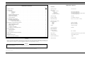
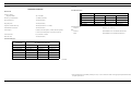
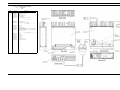
LBI-33055 Maintenance Manual MDX UHF MOBILE RADIO TABLE OF CONTENTS RF BOARD . . . . . . . . . . . . . . . . . . . . . SYSTEM BOARD . . . . . . . . . . . . . . . . . AUDIO/LOGIC BOARD . . . . . . . . . . . . . . AUDIO AMPLIFIER BOARD . . . . . . . . . . . FRONT CAP ASSEMBLY . . . . . . . . . . . . . LBI-39017 LBI-38842 LBI-39016 LBI-38844 LBI-38850 LBI-38974 PA BOARD . . . . . . . . . . . . . . . . . . . . . . . . . . . . LBI-39051 SERVICE SECTION . . . . . . . . . . . . . . . . . . . . . . . LBI-39018 ericssonz . . . . . . . . . . . . . . . . . . . . . . . . . . . . . . . . . . . Ericsson Inc. Private Radio Systems Mountain View Road Lynchburg, Virginia 1-800-528-7711 (Outside USA, 804-528-7711) Printed in U.S.A. LBI-33055 SPECIFICATIONS* TABLE OF CONTENTS Page GENERAL SPECIFICATIONS* . . . . . . . . . . . . . . . . . . . . . . . . . . . . . . . . . . . . . . . . . . . . . . . . . . . 1 Operating Voltage 13.8 Volts ±15% DESCRIPTION . . . . . . . . . . . RF BOARD . . . . . . . . . . Synthesizer . . . . . . Transmitter . . . . . . Receiver . . . . . . . POWER AMPLIFIER BOARD AUDIO/LOGIC BOARD . . . FRONT CAP ASSEMBLY . . SYSTEM BOARD . . . . . . . Battery Drain Receiver (13.8 Vdc) Off Squelched Unsquelched Transmitter (13.8 Vdc) 0.01 Amperes (Maximum) 0.75 Amperes (Maximum) 3.5 Amperes (Maximum at 10 Watts audio, External Speaker) 13.0 Amperes (Maximum) Channel Spacing 12.5 kHz Frequency Stability ± 2.5 PPM (± 0.00025%) Temperature Range -20°C to +55°C (-22°F to +140°F) Dimensions (H X W X D) (Less Accessories) Height Width Depth 5.3 cm (2.1 inches) 18.2 cm (7.2 inches) 24.0 cm (9.5 inches) Weight 3.0 kg (6.6 pounds) Antenna Impedance 50 Ohms . . . . . . . . . . . . . . . . . . . . . . . . . . . . . . . . . . . . . . . . . . . . . . . . . . . . . . . . . . . . . . . . . . . . . . . . . . . . . . . . . . . . . . . . . . . . . . . . . . . . . . . . . . . . . . . . . . . . . . . . . . . . . . . . . . . . . . . . . . . . . . . . . . . . . . . . . . . . . . . . . . . . . . . . . . . . . . . . . . . . . . . . . . . . . . . . . . . . . . . . . . . . . . . . . . . . . . . . . . . . . . . . . . . . . . . . . . . . . . . . . . . . . . . . . . . . . . . . . . . . . . . . . . . . . . . . . . . . . . . . . . . . . . . . . . . . . . . . . . . . . . . . . . . . . . . . . . . . . . . . . . . . . . . . . . . . . . . . . . . . . . . . . . . . . . . . . . . . . . . . . . . . . . . . . . . . . . . . . . 3 3 3 3 3 3 3 3 3 ACCESSORIES AND OPTIONS . . . . . . PC PROGRAMMER OPTIONS . . . PC PROGRAMMED OPTIONS . . . Carrier Control Timer (CCT) . . . . . . . . . . . . . . . . . . . . . . . . . . . . . . . . . . . . . . . . . . . . . . . . . . . . . . . . . . . . . . . . . . . . . . . . . . . . . . . . . . . . . . . . . . . . . . . . . . . . . . . . . . . . . . . . . . . . . . . . . . . . . . . . . . . . . . . . . . . . . . . . . . . . . . . . 3 3 3 3 HARDWARE AND HARDWARE OPTIONS OPTION INTERFACE CABLE . . . . . NOISE SUPPRESSION KIT . . . . . . POWER CABLE . . . . . . . . . . . . EXTERNAL SPEAKER . . . . . . . . EXTERNAL ALARM HORN RELAY . . . . . . . . . . . . . . . . . . . . . . . . . . . . . . . . . . . . . . . . . . . . . . . . . . . . . . . . . . . . . . . . . . . . . . . . . . . . . . . . . . . . . . . . . . . . . . . . . . . . . . . . . . . . . . . . . . . . . . . . . . . . . . . . . . . . . . . . . . . . . . . . . . . . . . . . . . . . . . . . . . . . . . . . . . . . . . . . . . . . . . . . . . . . . . . . . . . . . . . . . . . . . . . . . . . . . . . . . . . . . . . 3 3 3 3 3 3 RADIO OPERATION . . . . . . . . . . . . . . . . . . . . . . . . . . . . . . . . . . . . . . . . . . . . . . . . . . USER INTERFACE . . . . . . . . . . . . . . . . . . . . . . . . . . . . . . . . . . . . . . . . . . . . . . . . 3 4 TRANSMITTER SCAN OPERATION . . . . . . . . . . . . . . . . . . . . . . . . . . . . . . . . . . . . . . . . . . . . . . . . . . 4 Frequency Range High Split Radio 485 - 505 MHz PUBLIC ADDRESS OPTION OPERATION . . . . . . . . . . . . . . . . . . . . . . . . . . . . . . . . . . . . . . 4 PARTS LIST . . . . . . . . . . . . . . . . . . . . . . . . . . . . . . . . . . . . . . . . . . . . . . . . . . . . . . . 5 Output Power 25 Watts (Intermittent duty cycle; EIA 20%) ASSEMBLY DIAGRAM . . . . . . . . . . . . . . . . . . . . . . . . . . . . . . . . . . . . . . . . . . . . . . . . 5 Audio Sensitivity 110 mV RMS (typical) INTERCONNECTION DIAGRAM . . . . . . . . . . . . . . . . . . . . . . . . . . . . . . . . . . . . . . . . . . 6 Spurious and Harmonics -70dBc Audio Distortion 5% (maximum) NOTICE! Repairs to this equipment should be made only by an authorized service technician or facility designated by the supplier. Any repairs, alterations or substitution of recommended parts made by the user to this equipment not approved by the manufacturer could void the user’s authority to operate the equipment in addition to the manufacturer’s warranty. Continued NOTICE! The software contained in this device is copyrighted by Ericsson Inc. Unpublished rights are reserved under the copyright laws of the United States. This manual is published by Ericsson Inc., without any warranty. Improvements and changes to this manual necessitated by typographical errors, inaccuracies of current information, or improvements to programs and/or equipment, may be made by Ericsson Inc., at anytime and without notice. Such changes will be incorporated into new editions of this manual. No part of this manual may be reproduced or transmitted in any form or by any means, electronic or mechanical, including photocopying and recording, for any purpose, without the express written permission of Ericsson Inc. Copyright © April 1995, Ericsson Inc. 1 LBI-33055 Continued Continued SPECIFICATIONS* ENVIRONMENTAL RECEIVER STANDARD METHODS PROCEDURES Frequency Range High Split Radio 485 - 490 MHz Mechanical Shock 516.2/Proc 1 516.3/Proc 1-6 516.4/Proc 1-6 Sensitivity (12 dB SINAD) -116 dBm (maximum) Humidity 507.1 507.2 507.3 Spurious Rejection -70 dB (maximum) Salt Fog 509.1/Proc 1 509.2/Proc 1 509.3/Proc 1 Blowing Dust 510.1/Proc 1 510.2/Proc 1 510.3/Proc 1 Image Rejection -70 dB (maximum) Driven Rain 506.1/Proc 1 506.2/Proc 1 506.3/Proc 1 Adjacent Channel Selectivity -60 dB (maximum at ± 12.5 kHz) U.S. Forest Service Vibration: Intermodulation Distortion -65 dB (maximum) Audio Output 10 Watts (External Speaker); 4 Watts (Internal Speaker) 7.5 Watts (External Speaker with remote mount kit) Audio Distortion 5% (maximum at 1 kHz) Hum and Noise -35 dB (maximum) Methods 7.15.1 and 8.11.1 EIA Vibration Shock: RS152B Method 14.3 and RS206C Method 24.2 RS152B Method 15 and RS204C Method 25 ENVIRONMENTAL STANDARD METHODS PROCEDURES Mil-810C Mil-810D Mil-810E High Temperature 501.1/Proc 2 501.2/Proc 2 501.3/Proc 2 Low Temperature 502.1/Proc 2 502.2/Proc 2 502.3/Proc 2 Low Pressure 500.1/Proc 1 500.2/Proc 1 500.3/Proc 1, 2 Solar Radiation 505.1/Proc 1 505.2/Proc 1 505.3/Proc 1 Temperature Shock 503.1/Proc 2 503.2/Proc 1 503.3/Proc 1 Vibration 514.2/C8, P1 514.3/Proc 8 514.4/C8, P1 Continued * These specifications are intended primarily for use by a service technician. Refer to the appropriate Specification Sheet for complete specifications. 2 LBI-33055 DESCRIPTION The UHF MDX Mobile Radio is a synthesized, wide band radio that uses integrated circuits and microcomputer technology to provide high performance in conventional communications systems. The UHF MDX Mobile radio provides 40 Watts of RF power output in the 403-440, 440-470 or 470512 MHz bands. All radio functions are stored in a programmable Electrically Erasable PROM (EEPROM). • Serial Programming Interface Module TQ3370 • Programming Cable (19B801417P10) TQ3372 • MDX Series Programming Software TQ3346 With the interface equipment and software, the computer can be used to program (or re-program) customer system frequencies, and options. Selection of options is done during radio initialization using the PC programmer. The UHF MDX Mobile Radio assembly contains the following circuit boards and assemblies: • Power Amplifier 19D904792 • RF Board 188D5062 • System Board 19D901891 • Audio/Logic Board 19D903963 • Audio Amplifier Board 19D904025 • Front Cap Assembly 19D904151 The circuit boards are all mounted on a main casting to provide easy access for servicing. Interconnect plugs are used to connect the boards to eliminate pinched wires and other wiring problems. RF BOARD The RF Board includes the programmable frequency synthesizer, transmitter exciter, receiver front-end and Intermediate Frequency (IF) circuitry. Synthesizer The synthesizer circuit generates all transmit and receive RF frequencies. The synthesizer frequency is controlled by the microprocessor located on the Audio/Logic Board. Frequency stability is maintained by a temperature compensated reference oscillator module. Transmit audio is processed on the Audio/Logic Board and applied to the synthesizer to modulate the Voltage Controlled Oscillator (VCO) and the Temperature Controlled Xtal (crystal) Oscillator (TCXO). The buffered VCO output drives both the transmitter exciter and the receiver mixer. Transmitter The transmitter consists of a fixed-tuned exciter module, PA module and a power control circuit. The PA module provides RF output to drive the antenna. The power control circuit controls the PA module to maintain constant output power across the band. The RF output level is internally adjustable for rated power. A thermistor control circuit protects the PA from overheating by linearly reducing the power output level with increasing temperature. Receiver The dual conversion receiver circuit consists of a front-end section, 45 MHz first IF, a 455 kHz second IF and Frequency Modulation (FM) detector. All audio processing and squelch functions are accomplished on the Audio/Logic Board. POWER AMPLIFIER BOARD The PA Board amplifies the RF board output, then connects it back to the RF board where it is coupled through a PIN diode antenna switch, a low-pass filter and a directional coupler to provide 40 watts power output at the antenna connector. AUDIO/LOGIC BOARD The Audio/Logic Board provides all audio and digital processing of the receive and transmit audio for digital processing by the Logic Board. This board also contains audio filtering, conventional analog tone processing and the receiver squelch. The Audio/Logic Board controls the operation of the radio and digitally processes the receiver and transmit audio. The board contains a microprocessor and associated memory circuits including an Electrically Programmable Read Only Memory (EPROM) for controlling the processor and a programmable "personality" memory, an EEPROM to store customer frequencies, tones and options. The microprocessor provides control data to the Audio Signal Processor (ASP) conventional tone generation and detection, frequency data for the synthesizer and sends and receives data to/from another microprocessor on the Display Board for the alphanumeric LED display. FRONT CAP ASSEMBLY the received audio in the discriminator and internal/external speaker audio paths. A 10-watt power amplifier is provided on the board to drive a 4-ohm internal/external speaker. HARDWARE AND HARDWARE OPTIONS The Front Cap Assembly also contains the display board which includes the LED Display, the keyboard and interface/drive circuitry. In Scan models the internal speaker is mounted in the front cap. In System radios there is no speaker, to allow room for the additional keys. The location and placement of system hardware options is shown on the MDX Conventional Mobile Radio Interconnection Diagram 188D5198. SYSTEM BOARD Option Interface Cable (19C851585P18) is used to bring all option connections from the System Board through the back of the radio to the outside. This cable is required with all external options. Option Interface Cable (19C851585G14) can be used for all external options except data. The system board controls the main input power to the radio. The IGNITION SENSE input lead provides the necessary signals to the MOSFET switching circuit. The board also interfaces all option connections from the internal boards in the radio with the optional items outside of the radio. All external options for the radio, interconnect to the System Board through the back of the radio using an optional cable. ACCESSORIES AND OPTIONS PC PROGRAMMER OPTIONS The radio is programmed using an IBM compatible Personal Computer (PC) equipped with an RS-232 serial interface unit and the cable between the PC and the unit. An auxiliary power supply for the unit is also included but is not needed to program the radio. OPTION INTERFACE CABLE NOISE SUPPRESSION KIT Noise Suppression Kit consists of filter 19A148539G1 and Installation Manual LBI-31363. This kit is available for installations where excessive alternator or electrical noises, present on the power cable, do not permit the radio to operate properly. Refer to the Interconnect Diagram for the radio and options. POWER CABLE The 18-foot Power Cable (19B801358P17) is available for installations requiring more than the standard 9-foot cable. Option TQ3372 provides the MDX UHF radio programming cable between the PC interface unit and the radio microphone jack. EXTERNAL SPEAKER PC PROGRAMMED OPTIONS External Speaker and Cable provides the user a 5-inch waterproof speaker in a LEXAN housing (19A149590P1), an 18-inch, external speaker cable (19A149590P8) is included. A 16-foot cable (19A149590P10) is also available. Carrier Control Timer (CCT) The Carrier Control Timer turns off the transmitter after the microphone PTT switch has been keyed for a pre-programmed time period. A pulsing alert tone warns the operator to unkey and then key again the PTT to continue the transmission. The timer can be programmed, using the PC programmer. Any time period between 0 seconds and 4.1 minutes can be programmed in 10 second increments. The timer can be enabled or disabled for each channel. When using the external speaker, the internal speaker should be disconnected. The internal/external speaker switch option PMPL3D allows use of both speakers (Refer to the Interconnection Diagram). EXTERNAL ALARM HORN RELAY External Alarm Horn Relay (19A705499P1) can sound the vehicle horn when a call is received. The option connects to Pin 13 of cable (19C851585P14) and is enabled through the front panel switch. The Front Cap Assembly contains the Audio Amplifier Board. The Audio Amplifier Board provides compression of the microphone audio. It also provides audio compression for 3 LBI-33055 RADIO OPERATION 1. Confirm that the radio is turned on. If not, press the POWER switch. A complete set of operating instructions for the MDX UHF radio are provided in Operator’s Manual. 2. If the SCAN indicator is lit, press and release the SCAN switch to disable the scan function. In the conventional mode of operation, the user selects a channel and communicates on that channel in the conventional mode. A system refers to a set of channels and a channel is a transmit/receive radio frequency pair. The exact operation of any radio depends upon the operating mode, the programming of the radio and the particular radio system. Most features described in these operating instructions can be enabled or disabled through programming. Both of these important factors must be considered when addressing the following instructions. 3. Select the desired group using the CHANNEL UP and DOWN switch. The SELECTED group does not necessarily have to be a group in the scan list. The SELECTED group will be temporarily entered into the scan list and scanned until the SELECTED group is changed. 4. Press the programmed flex key mapped to scan add/delete to add the group to the scan list. The S indicator will be shown in the display to indicate that the group is now in the scan program. When scan is turned off by pushing the SCAN switch, the radio will return to the SELECTED group. 5. Repeat steps 2 through 5 for each group to be added to the scan list. Operating controls are located on the radio front panel and microphone. The Front panel Light Emitting Diode (LED) display provides radio status and communication control information for the operator. The keypad is used for activation of various features and functions. Turning The Radio On/Off The radio is turned On/Off by pressing the PWR button in the upper left corner of the front panel. To turn the radio OFF press the PWR button again. SCAN OPERATION The SCAN function allows monitoring of receive groups. All scan functions are retained in memory, even if the 12 Volt battery is disconnected. 1. Confirm that the radio is on. If not, press the power switch. While no signal is being received, the channel indicator will always show the SELECTED group. When an active group is received, the channel indicator will show the received group. 2. If SCN indicator is lit, press and release the SCAN switch to disable scan function. SCN Indicator 3. Select the desired group to be removed from the scan list using the CHANNEL UP or DOWN switches. 4. Press the programmed flex key mapped to scan add/delete until the scan indicator is off. This removes the selected group from the scan list. 5. Repeat preceding steps 2 through 5 for each group to be removed from the scan list. REVIEWING THE SCAN LIST 1. Confirm that the radio is turned on. If not, press the POWER switch. 2. If the SCAN indicator is lit, press and release the SCAN switch to disable the scan function. 3. Select each group (one at a time) using the CHANNEL UP or DOWN switch and confirm groups included on the scan list. The scan indicator (S) will light for each group programmed. TO PROGRAM SCAN GROUPS The selection of scan groups is front panel programmable using the programmed flex key or the menu mode. DISPLAY Channel Indicator DELETE SCAN GROUP(S) USER INTERFACE transmitting. When a signal is being received, the radio reverts to this group for transmitting. When a signal is being received, the radio can be PC programmed to either revert to the SELECTED group or remain on the received group. When the SCAN button is pushed, the radio will light the SCAN indicator and begin scanning. TRANSMITTING WHILE IN SCAN Transmitter operation in scan is determined by the PC programming of the radio personality. Off-Hook Scan Not Enabled (default): With off-hook scan not enabled (normal default condition), all scanning will stop when the microphone is placed off-hook. The SCN indicator will flash to show all scanning has stopped. If a signal is not being received when the microphone is placed off-hook, the radio will transmit on the SELECTED group. If a signal is being received when the microphone is placed offhook, the radio can be PC programmed (using the "scan transmit option" to either stay on the receive group or revert to the SELECTED group. When the microphone is placed back onhook, the radio will immediately start scanning, even if the received group was still active. Off Hook Scan Enabled: NOTE The following details how to add/delete groups using the flex key mapped to scan add/delete. The alternative is to select "SCAN A/D" in the menu mode. Select the desired group using the "-" button and add/delete group using the "+" button. 4 USING THE RADIO WITH SCAN THE SELECTED GROUP The SELECTED group is the group in the display when scan is turned on by pushing the SCAN switch. When a signal is not being received, the radio reverts to this channel for With off-hook scan enabled, moving the microphone off hook will not affect scan operation. The radio will continue scanning. If a signal is not being received, the radio will transmit on the SELECT group. If a signal is being received, the radio can be PC programmed (using the "scan transmit group" option) to either stay on the receive group or revert to the SELECTED group when the microphone PTT is keyed. PC PROGRAMMING SCAN OPTIONS 1. Scan Transmit Group: SELECTED group (default): The radio will always revert to SELECTED group when the microphone PTT is keyed or when the microphone is placed offhook (if off-hook scan is disabled). If signals not being received, the radio will transmit on the SELECTED group. 2. Off-Hook Scan Enable: NO: (default): The radio will stop scanning and flash the SCN indicator when the microphone is off-hook. See the "scan transmit group" description above to program where the radio will transmit. YES: The radio will continue scanning with the microphone off-hook. See the "scan transmit group" description above to program where the radio will transmit. PUBLIC ADDRESS OPTION OPERATION If the Public Address Option is present, the radio may be used as public address amplifier. Press the programmed flex key or scroll through the menu to select the PA option (Scan must be off). The LED display will show "Pub Addr". When the microphone is keyed, the radio no longer transmits, but allows the microphone audio to feed the speaker. Adjust the VOLUME for the desired level. Press the programmed flex key or scroll through the menu a second time to disable the PA option. The display will return to normal channel display. Changing groups or turning on Scan will also turn the operation off. The Public Address microphone audio normally feeds an external speaker. An ON/OFF switch, which is mounted on or near the radio, allows selecting either the internal or external speaker for the receiver audio. The ON/OFF switch turns the receiver audio on or off to the external speaker. This switch still functions for the receiver audio with the PA option disabled. PARTS LIST ASSEMBLY DIAGRAM LBI-33055 MDX UHF MOBILE RADIO ASSEMBLY 19D904183P5 Issue 1 SYMBOL PART NO. DESCRIPTION ---------------------ASSEMBLIES-------------------- A1 188D5062G4 RF Board (470 - 512 MHz) A3 19D901891G3 System Board A4 19D904025G2 Audio Amplifier Board A5 19D903963G2 Audio/Logic Board 19D904792G3 Power Amplifier Board (470 - 512 MHz) ---------------------KITS-------------------- 344A4253G1 Hardware Kit No. 1 344A4256G5 Hardware Kit No. 2 (470 - 512 MHz) 19A704884P4 J1 To J103 ----------------------------CABLES-------------------------- 19A704884P4 J2 To J102 19B801467P1 J3 to J705 to J704 19B801253P5 Cable, Ribbon, between J707 on Audio Ampliffier Board to P707 on Display Board 19A705235P3 Cable, Ribbon, between J901 on Audio Amplifier Board to J902 on System Board --------------------------MISCELLANEOUS------------------------ 19D904027P1 Casting 19C337683G2 Bracket 19D904185G1 Cover, Bottom 19D904186G1 Cover, Top 19D904187G1 Panel, Front 19B801358P18 Cable, 9 Foot, Power 19B235310P10 Nameplate, Combination 5 LBI-33055 MDX UHF Mobile Radio (19D904183, Sh. 5, Rev. 0) 6 ASSEMBLY DIAGRAM ASSEMBLY DIAGRAM LBI-33055 MDX UHF Mobile Radio (Made From 19D904183, Sh. 7, Rev. 12) 7 LBI-33055 MDX UHF Mobile Radio (188D5198, Sh. 1, Rev. 0) 8 INTERCONNECTION DIAGRAM INTERCONNECTION DIAGRAM LBI-33055 MDX UHF Mobile Radio (188D5198, Sh. 3, Rev. 0) 9 LBI-33055 MDX UHF Mobile Radio (188D5198, Sh. 4, Rev. 0) 10 INTERCONNECTION DIAGRAM LBI-33055 This page intentionally left blank 11