1
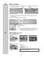
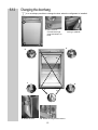
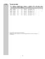
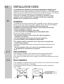
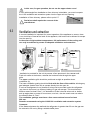
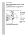
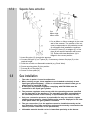
MANUAL ABSORPTION REFRIGERATOR for RECREATIONAL VEHICLES RM 6270 (L) RM 6271 (L) RM 6290 (L) RM 6291 (L) RM 6360 (L) RM 6361 (L) RM 6400 (L) RM 6401 (L) EN English Typ C40 / 110 T.B. 04/02 © Dometic GmbH - 2002 - Subject to change without notice - Printed in Germany These operating instructions should be kept in a safe place. If this device is passed on, please include these operating instructions with it. 2 TABLE OF CONTENTS 1.0 2.0 3.0 INTRODUCTION FOR YOUR SAFETY 4 4 2.1 Warning and safety notices 4 2.2 Coolant 4 WARRANTY AND CUSTOMER SERVICE 5 3.1 5 Damage in transit 4.0 5.0 DESCRIPTION OF MODEL REFRIGERATOR GUIDE 6.0 INSTALLATION GUIDE 17 6.5 6.6 6.7 6.8 6.9 20 21 22 23 25 5.1 5.2 5.3 5.4 5.5 5.6 5.7 5.8 5.9 5.10 5.11 5.12 5.13 5.14 5.15 5.16 5.17 5.18 5.19 6.1 6.2 6.3 6.4 Cleaning Switching on the refrigerator Switching off the refrigerator Defrosting Storing food Making ice cubes Door locking Winter operation Interior light Changing the decor panel Positioning the storage racks Changing the doorhang Troubleshooting Maintenance Environmental hints Disposal Energy-saving tips Technical data Declaration of conformity Installation Draught-free installation Ventilation and air extraction Installation of the ventilation system Securing the refrigerator Installation recess Fume extraction Gas installation Electrical installation 3 5 5 5 6 8 9 9 9 9 10 10 11 11 12 13 13 14 14 14 15 16 17 18 19 20 1.0 INTRODUCTION You have made an excellent choice in selecting the Dometic Absorption Refrigerator. We are sure that you will be fully satisfied with your new appliance in all respects. The appliance, which works silently, meets high quality standards and guarantees the efficient utilisation of resources and energy throughout its entire life cycle, during manufacture, in use and when being disposed of. Before you start to use the appliance, please read the installation and operating instructions carefully. The refrigerator is designed for installation in leisure vehicles such as caravans or motorcaravans. The appliance has been certified for this application in accordance with EU Gas Directive 90/396/EEC. 2.0 2.1 FOR YOUR SAFETY Danger Warning and safety notices Attention Never use a naked flame to check the appliance for leaks. Protect children! When disposing of the refrigerator, remove all refrigerator doors and leave the storage rack in the refrigerator. This will prevent accidental locking in or suffocation. If you smell gas: - close the locking tap of the gas supply and the valve on the cylinder. - open the windows and leave the room. - do not switch on anything electrical. - extinguish naked flames. Never open the cooling unit; it is under high pressure. Work on the gas, flue system and electrical components must only be carried out by qualified service personnel. It is imperative that the operating pressure should correspond to the data given on the model plate of the appliance. Compare the operating pressure data given on the model plate with the data on the pressure monitor of the liquid gas cylinder. Liquid gas cylinders may only be changed by qualified personnel. Gas operation of the appliance is not permitted while travelling on ferries. Covers ensure electrical safety and must only be removed using a tool. The appliance must not be exposed to rain. The refrigerator is not suitable for the proper storage of medications. 2.2 Coolant Ammonia is used as a coolant. This is a natural compound also used in household cleaning agents (1 litre of Salmiak cleaner contains up to 200g of ammonia - about twice as much as is used in the refrigerator). Sodium chromate is used for corrosion protection (less than 2% of the coolant). In the event of leakage (easily identifiable from the unpleasant odour): switch off the appliance. air the room thoroughly. inform the authorised Customer Service department. 4 3.0 WARRANTY AND CUSTOMER SERVICE Warranty arrangements are in accordance with EC Directive 44/1999/CE and the normal conditions applicable for the country concerned. For warranty or other servicing, please contact our Dometic Service department. Any damage due to improper use is not covered by the warranty. The warranty does not cover any modifications to the appliance or the use of non-original Dometic parts; the warranty does not apply if the installation and operating instructions are not adhered to and no liability shall be entertained. Parts can be ordered throughout Europe from our Dometic Service department. Your Service Centre contact numbers numbers are found in the European Service Network booklet When contacting Dometic Service, please state the model and product numbers, together with the MLC Code, if applicable. You will find this information on the data plate inside the refrigerator. 3.1 Damage in transit After removing the packaging, check whether the refrigerator has been damaged during transportation. Any damage sustained in transit must be reported to the transportation company concerned no later than seven days after delivery of the goods. 4.0 DESCRIPTION OF MODEL e.g. RM 6270 L Refrigerator Mobil / Mobile Absorber Refrigerator 5.0 5.1 L with interior light Last digit 1 = automatic ignition Last digit 0 = manual ignition REFRIGERATOR GUIDE Cleaning Before using the refrigerator, it is advisable to clean the appliance both inside and out. Use a soft cloth and lukewarm water with a mild detergent. Then rinse the appliance with clean water and dry thoroughly. Remove dust from the refrigerator unit at yearly intervals using a brush or soft cloth. To avoid deterioration of materials: Do not use soap or hard, abrasive or soda-based cleaning agents. Do not allow the door seal to come into contact with oil or grease. 5 5.2 Using the refrigerator The refrigerator is silent in operation. When the appliance is first put into operation, there may be a mild odour which will disappear after a few hours. Ensure the living area is well ventilated. The freezer compartment should be cold about one hour after switching on the refrigerator. The refrigerator will take several hours to reach its operating temperature. 5.2.1 Controls A. Manual Ignition (e.g. RM 6270L) A B C A = energy selector switch B = gas/electric thermostat C = manual ignition button (Piezo ignition) B. Automatic Ignition ( e.g. RM 6271L) B A A = energy selector switch B = gas/electric thermostat D = automatic ignition indicator Note: The refrigerator is equipped to operate off mains power, DC or liquid gas. The desired power option is selected by means of energy selector switch (A). Energy selector switch (A) has four settings: AC mains power, DC (12V), gas (liquid gas), O (off). Off AC DC Gas 6 D 5.2.2 Electrical operation 1. 12V DC The refrigerator should only be used while the motor is running. 1. Set energy selector switch (A) to. The refrigerator operates without thermostatic control (continuous operation). A 2. Mains power This option should only be selected where the supply voltage of the connection for power supply corresponds to the value specified on the data plate. Any difference in values may result in damage the appliance. A 5.2.3 1. Set energy selector switch (A) to. B 2. Use rotary switch (B) to regulate the temperature in the main refrigerator compartment. Gas operation The refrigerator should only be operated using liquid gas (propane, butane). Operation using gas is prohibited in petrol stations. 1. Open the valve of the gas cylinder 2. Open the shut-off valve to the gas supply. Proceed to the description that applies to YOUR model. 1. Manual ignition 1. Set energy selector switch (A) to gas. 2. Press and hold rotary switch. B A C 3. Activate Piezo ignition (C) several times at intervals 1-2 seconds. 7 4. Check the inspection glass to see whether there is a flame (the inspection glass is inside the refrigerator at the bottom left). 5. 6. 7. 8. Keep rotary switch (B) depressed for another 10-15 seconds, then release. Check the inspection glass to see whether a flame is burning. Repeat the entire process if the flame has gone out. Use rotary switch (B) to regulate the temperature in the main refrigerator compartment. 2. Automatic ignition A B 2. Press and hold rotary switch (B). 1. Set energy selector switch (A) to Gas. D 3. The ignition process is activated automatically, accompanied by a ticking sound; the indicator lamp (D) will flash. Upon successful ignition, the sound and the flashing will stop. 4. Keep rotary switch "B" depressed for another 10-15 seconds, then release. 5. If the flame goes out, the ignition system will repeat the ignition process automatically. 6. Adjust the temperature in the main refrigerator compartment using rotary switch "B". All refrigerators, whether manual or automatic ignition, are equipped with automatic flame protection, which automatically cuts off the supply of gas approximately 30 seconds after the flame goes out. When using for the first time, and after changing the gas cylinder, the gas pipes may contain air. By means of brief operation of the refrigerator and any other gas appliances (e.g. cookers), air is removed from the gas pipes. The gas will then ignite without delay. 5.3 Switching off A 1. Set energy selector switch (A) to position "0" (OFF). The appliance is now fully switched off. 2. Secure the door open by means of the door stop. The door will be slightly ajar; this is to prevent mould from forming inside the appliance. Switching off gas operation If the refrigerator is to be taken out of service for an extended period of time, the on-board shut-off valve and the cylinder valve must be closed. 8 5.4 Defrosting As time goes by, frost builds up on the fins. When the layer of frost is about 3mm thick, the refrigerator should be defrosted. 1. Switch off the refrigerator, as described in Section 5.3 - "Switching off". 2. Remove the ice cube tray and food. 3. Leave the refrigerator door open. 4. After defrosting (freezer compartment and fins free of frost), wipe the cabinet dry with a cloth. 5. Use a cloth to mop up the water from the freezer compartment. 6. Switch the refrigerator back on again. The layer of ice must never be removed forcibly, nor may defrosting be accelerated using a heat source. Note: Water thawing in the main compartment of the refrigerator runs into an appropriate container at the back of the refrigerator. From there, the water evaporates. 5.5 Storing food Always store food in sealed containers, aluminium foil or similar. Never put hot food into the refrigerator; always let it cool first. Products that could emit volatile, flammable gases must not be stored in the refrigerator. The two-star freezer compartment is suitable for making ice cubes and for short-term storage of frozen food. It is not suitable as a means of freezing foods. 5.6 Making ice cubes Ice cubes are best frozen overnight. At night, the refrigerator has less work to do and the unit has more reserves. 1. Fill the ice cube tray with drinking water. 2. Place the ice cube tray in the freezer compartment. Only use drinking water! 5.7 Door locking Park-position: 9 5.8 Winter operation 1. Check that the ventilation grills and the extractor have not been blocked by snow, leaves or similar. Lower ventilation grille Upper ventilation grille with flue vent 2. When the ambient temperature falls below 8°C, the optional winter covers should be fitted. This protects the unit from excessively cold air. 3. Affix the cover and fasten it. It is also recommended that the winter covers should be used when the vehicle is taken out of service for an extended period of time. 5.9 Interior light (when fitted) Changing the light bulbs 1. 2. 1. Remove cover. 90° 2. Detach defective light bulb. 3. Fit new light bulb. Note: for 12V DC : 1 light bulb 8V, 2W for 24V DC : 2 light bulbs 28V, 1,5W 4. Clip the cover back in place. Please contact Dometic Service centres for replacement light bulbs. 10 5.10 Changing the decor panel 1. Open the door and loosen the hinge screw. 4. Remove the decor plate and insert a new decor plate. 5.11 2. Take off the door by moving it upwards. 5. Screw the door strip back in position. 3. Unscrew the door strip (3 screws). 6. Put the door back on. Dimensions of the panels in mm: Model Height RM 6270/71 713+/-1 RM 6360/61 713+/-1 Width 453,5+1 453,5+1 Thickness 3,2 3,2 RM 6290/91 RM 6400/01 491,5+1 491,5+1 3,2 3,2 718+/-1 718+/-1 Positioning the storage rack Dismantling: 2. 1. 1. Loosen the front and back securing brackets. 2. Move the storage rack to the left and remove it. To fit the storage rack, the reverse order applies. 11 7. Tighten the hinge screw. 5.12 Changing the doorhang It is not always possible to change the door when the refrigerator is installed. 1. Open the door, unscrew the hinge screw and keep it to hand. 2. Take off the door by moving it upwards. 6. 5. 4. 5. 7. 4. 3. 9. Attach the door. 8. 10. Screw the hinge screw back in. 12 5.13 Troubleshooting Before calling the authorised Service department, please check whether: 1.The instructions in the section "Using the refrigerator" have been followed. 2. The refrigerator is not tilted excessiveley. 3. It is possible to operate the refrigerator with an available power source. Problem 1: The refrigerator does not work in gas operation mode. Possible cause Action you can take a.) Gas bottle empty. a.) Change gas bottle. b.) Is the supply cut-out device open?. b.) Open the cut-out device. Problem 2: The refrigerator does not work on 12V. Possible cause Action you can take a.) Fit new fuse. a.) On-board fuse defective. Problem 3: The refrigerator does not cool sufficiently. Possible cause 5.14 Action you can take a) Inadequate ventilation to the unit. a) Check that the ventilation grilles are not covered. Check whether the refrigerator was installed properly (Installation Guide). b) The thermostat setting is too low. b) Turn the thermostat to a higher setting. c) There is too much ice on the condenser. c) Check that the refrigerator door seals when shut. d) Too much warm food put inside. d) Let food cool down first. Maintenance EN 1949 stipulates that the appliance´s gas equipment and its associated fume system must be inspected after installation and a certificate issued. Afterwards a qualified technician must inspect according to EN 1949 every two years and a certificate issued. It is the users responsibily to arrange for inspections after purchase. It is recommended that the gas burner be inspected and cleaned as necessary at least once a year. 13 5.15 Environmental hints 5.16 Disposal Refrigerators manufactured by Dometic GmbH are CFC-free. Ammonia (a natural compound of hydrogen and nitrogen) is used in the cooling unit as a coolant. The non-ozone-hazardous cyclopentan is used as a propellant in the manufacture of the PU foam insulation. In order to ensure that the recyclable packaging materials are re-used, these should be sent to the usual local collection system. The appliance should be transferred to a suitable waste disposal company that will ensure re-use of the recyclable components and proper disposal of the rest. For eco-friendly draining of the coolant from all absorber refrigeration units, a suitable disposal plant should be used 5.17 Energy-saving tips At an average ambient temperature of approx. 25°C, it is sufficient to operate the refrigerator at the middle thermostat setting (for both gas and mains voltage). Where possible, always store goods that have previously been cooled. Do not position the refrigerator in direct sunlight. Constant circulation of air must be supplied to the refrigerator unit. Defrost regularly. Open the door only for a short time when removing goods from the refrigerator. Run the refrigerator for about 12 hours before filling it. 14 5.18 Technical data Model Dimensions H x W x D (mm) depth incl. door RM 6270 RM 6271 RM 6290 RM 6291 RM 6360 RM 6361 RM 6400 RM 6401 821x486x541 821x486x541 821x525x541 821x525x541 821x486x541 821x486x541 821x525x541 821x525x541 Groos capacity Usable Connection incl. freezer capacity of Mains / Battery compartment freezer compartment 77 lit. 77 lit. 86 lit. 86 lit. 88 lit. 88 lit. 97 lit. 97 lit. 9,5 lit. 9,5 lit. 10,5 lit. 10,5 lit. 9,5 lit. 9,5 lit. 10,5 lit. 10,5 lit. 125W / 120W 125W / 120W 125W / 120W 125W / 120W 135W / 130W 135W / 130W 135W / 130W 135W / 130W * Consumption electricity / gas in 24 hrs Netweight approx. 2,5KWh / 270g approx. 2,5KWh / 270g approx. 2,5KWh / 270g approx. 2,5KWh / 270g approx. 2,6KWh / 270g approx. 2,6KWh / 270g approx. 2,6KWh / 270g approx. 2,6KWh / 270g 26kg 26kg 27kg 27kg 28kg 28kg 29kg 29kg Ignition Ignition Piezo Reigniter X X X X X X X We reserve the right to make technical changes. *Average consumption measured at an average ambient temperature of 25°C in pursuance of ISO Standard. 15 X Steppedcabinet X X X X 5.19 Declaration 16 6.0 INSTALLATION GUIDE On installation of the appliance, the technical and administrative regulations of the country in which the vehicle will first be used must be adhered to. Otherwise the refrigerator must be installed as described in these instructions. In some OEM applications it may not be possible for these instructions to be followed exactly. In this case an authorised Dometic representative may issue supplementary instruction In Europe, for example, gas appliances, cable laying, installation of gas cylinders, as well as approval and checking for leaks must comply with DIN EN 1949 for liquid gas units in vehicles. 6.1 Installation The appliance and its fume extraction shall be installed in such a way as to be accessible for servicing at all times and must be capable of easy removal and installation. The appliance may only be installed by authorised personnel. Installation and connection of the appliance must comply with the latest technical regulations, as follows: Technical regulations, liquid gas (TRF 1996) Technical regulations, DVGW Worksheet G 607 (DIN EN 1949) Technical regulations, EN 732 The electrical installation must comply with national regulations ( EN 60335-1 for Europe). The gas installation must comply with national regulations. Local and building control department requirements The appliance shall be installed in such a way that it is shielded from excessive heat radiation. Excessive heat impairs performance and raises the energy consumption of the refrigerator. Any installation that is not carried out by qualified persons will jeopardize the manufacturer's guarantee. 6.1.1 Side Installation If the appliance is installed on the same side of the vehicle as the entrance door, it is desirable that the door does not cover the refrigerators vents. If this cannot be avoided there must be a gap of at least 25mm between the door and the vents. 6.1.2 Rear installation If the refrigerator is mounted at the rear of the vehicle you must ensure the lower grille is not covered by the bumper or rear lights. This would be prevent the air from circulating properly and cause problems in warm weather. Air vent grille not blocked: OK! Fig.2 17 6.2 Draught-free installation Your refrigerator must be sealed in accordance with EN 1949. Illustrated below are two typical approved methods of sealing. Proposal 1: Insert lipped seals (A) into the installation recesses at the bottom and at each side. Insert deflector plate (B), fitted with a lipped seal (A) of heavy-duty, nonflammable material, into the installation recess (see Fig. 1). Insert deflector plate (B) in such a way that the hot air escapes through the air vent grating into the open air. Affix the discharge plate to the caravan wall, not to the refrigerator! In addition, discharge plate (B) with its lipped seal (A) must seal the refrigerator off from the living area (see Fig. 1). Ensure that the refrigerator is installed level in the recess. Fig.1 Proposal 2: Another option is to provide the refrigerator with a cowl (A). The cowl (A) should ideally be affixed to the caravan wall, not to the refrigerator. Insert sealing strips at the bottom and sides of the cover. Finally, push the refrigerator into the cover from the front. Both of these installation options facilitate the removal and installation of the appliance for servicing. Comment: Other methods of sealing may be approved. However the chosen method must prevent draughts entering the living space of the caravan or motorhome. Failure to seal correct ly will allow warm air to collect around the refrigerator and its performance will be affected. If the cavity between the caravan wall and the refrigerator is sealed so that fumes cannot penetrate the living area it is possible to vent the flue gas directly through the upper grille without using the aluminium flue pipe. For this installation method, it is recommended that the same air vent grille should be used at the top and at the bottom (L200), and that the T-piece of the flue pipe is turned 45 degrees. 18 In this case, for gas operation, do not use the upper winter cover! If even with draught-free installation a fume chimney is desirable, you must incorporte the L100 ventilation and extraction system into the upper air vent opening. Installation of fume chimney: please refer to point 6.7. Deviations shall require the consent of the manufacturer. 6.3 Ventilation and extraction A correct installation is important for correct operation of the appliance to ensure, there is no a build-up of heat at the back of the appliance; this heat must be allowed to escape into the open air. In the event of high ambient temperatures, full performance of the cooling unit can only be achieved by means of adequate ventilation and extraction. 15-20mm 13cm² without step 15-20mm 13cm² with step Ventilation is provided for the unit by means of two apertures in the caravan wall. Fresh air enters at the bottom, extracts the heat and exits through the upper grille. The upper ventilation grille should be positioned as high as possible above condenser (A). The lower ventilation grating should be flush with the floor of the vehicle, allowing any gas leakages (heavier than air) to escape directly into the open air. If such an arrangement is not possible a hole must be provided under the refrigerator (not close to the burner) so that any leaking LP gas can escape. This must have an effictive area of at least 13cm². It is desirable to fit the hole with wire mesh or similar, and an angle plate to protect it from stones, mud etc., the wire mesh must not reduce the effective area of 13cm² The ventilation gratings must have a free cross-sectional area of at least 250 cm2. Dometic recommends using the L100/L200 ventilation and extraction system. Comment: If the distance between the wall and the refrigerator is greater than 20 mm the gap can be reduced to 20 mm by fitting a suitable baffle piece. 19 6.4 Installing the ventilation system To install the ventilation grilles, cut two rectangles (451mm x 156mm) in the outer wall of the vehicle (for position of the cuts, see point 6.3). 6.5 1. Seal the mounting frame, making it waterproof. 2. Insert the frame and screw into position. 4. Lock the ventilation grilles. 5. Clip the extractor insert in position (only for upper ventilation system) Securing the refrigerator 3. Insert the ventilation grilles. In the sidewalls of the refrigerator, there are four plastic sleeves with screws for securing the refrigerator. The sidewalls or rails attached for securing the refrigerator must be designed in such a way that the screws will remain firmly in place even when under increased load (while the vehicle is moving). Always insert screws through the sleeves provided; otherwise, structural parts embedded in the foam, such as cables, etc., may be damaged. Once the refrigerator is in its final position, secure the screws into the wall of the recess. The screws must penetrate through the sheet metal casing of the refrigerator. 20 6.6 Installation recess The refrigerator must be installed draught-free in a recess. The measurements of the recess are given in the table below. Step (A) is only required for cabinets with a step. Push the appliance far enough into the recess until the front edge of the refrigerator casing is flush with the front of the recess. Allow a gap of 15-20 mm between the back wall of the recess and the refrigeration unit. The floor of the recess must be level, allowing the appliance to be pushed easily into its correct position. The floor must be substantial enough to bear the weight of the appliance. Ensure that the refrigerator is installed level in the recess. Recess measurements: Width of recess = W Width of recess = W Model RM RM RM RM RM RM RM RM 6270 6271 6290 6291 6360 6361 6400 6401 Hight H 825 825 825 825 825 825 825 825 mm mm mm mm mm mm mm mm Width W 490 490 529 529 490 490 529 529 21 mm mm mm mm mm mm mm mm Depth T 515 mm 515 mm 515 mm 515mm 515 mm 515 mm 515 mm 515 mm Hight HSt 220 220 220 220 - mm mm mm mm Depth TSt 235 235 235 235 - mm mm mm mm 6.7 Fume extraction Fume extraction must be arranged in such a way as to provide complete extraction of all products of combustion to an area outside the living area. The flue system must slope in an upward direction in order to avoid a build-up of condensation. An installation that is not carried out by qualified persons causes a reduction in the cooling capacity and will jeopardize the manufacturer's guarantee. 6.7.1 Fitting the fume flue in the upper ventilation grille min. 10 mm max. 20 mm 4. Put cap (B) on flue pipe (C). 5. Insert extractor insert (A) into ventilation grille (D). This type of fume extraction allows use a winter cover. 22 1. Connect T-piece (E) to adaptor (F) or flue pipe (K) as required and affix with screw (G). Ensure that heat baffle (H) is lodged in the correct position. 2. Insert flue pipe with cover plate (C) through the appropriate aperture in frame (I) and connect to T-piece (E). If necessary, shorten flue pipe (C) to the required length. 3. Insert ventilation grille (D) into mounting frame (I) and fasten, using the locking handle on the left of the grille. 6.7.2 Separate fume extraction min. 10 mm max. 20 mm Cut: 80mm high 40mm wide 1. Cut an 80mm x 40mm rectangle in the outer wall of the caravan. The position of the cut must be appropriate to the particular model of refrigerator and installation conditions. 2. Connect T-piece (E) to adaptor (F) or flue pipe (K) as required and affix with screw (G). Ensure that heat distributor (H) is lodged in the correct position. 3. Insert flue pipe (C) through the aperture. 4. Connect flue pipe (C) to T-piece (E). If necessary, shorten flue pipe (C) to the required length. 5. Pack the cut with non-flammable material (e.g. Rock Wool). 6. Screw securing plate (D) into position. 7. Put cap (B) on flue pipe (C). 8. Screw on outer plate (A). 6.8 Gas installation The rules in point 6.1 must be adhered to. When running on gas, these appliances are intended exclusively to use liquid gas (propane/butane) - under no circumstances should town gas or natural gas be used (EN 27418). A fixed, pre-set pressure regulator complying with EN 12864 must be connected to the liquid gas cylinder. The pressure regulator must concur with the operating pressure specified on the data plate of the appliance. The operating pressure corresponds to the standard pressure of the country of specification (EN 1949, EN 732). Only one connection pressure is permissible for any one vehicle. A plate showing the permanent, clearly legible notice must be displayed in full view at the point where the gas cylinder is installed. The gas connection (1) to the appliance must be installed securely and at zero potential using tube connectors and must be securely connected to the vehicle (a hose connection is not permissible). Inflamable material should not be in immediate proximity to the burner. 23 The gas connection to the appliance is effected by means of a suitable coupling tube fitting L8, DIN 2353-ST, complying with Worksheet G607 of DVGW or EN1949 respectively. (e.g. Ermeto) The gas connection may only be carried out by a qualified personnel. SW 14 SW 17 Following proper installation, a testing for leakage and a flame test must be carried out by *qualified personnel in compliance with Worksheet G607 or EN1949 respectively. A certificate of testing must be issued. * qualified personnel Qualified personnel are accredited experts who are able, by virtue of their training and knowledge, to vouch for the correct implementation of the leakage test. The refrigerator must be equipped with a gas cock (C) in the supply line to allow the supply to be disconnected. Such a cutout device must be readily accessible to the user. C Gas-pressure Category mbar I3P(30) 30 I 3P(37) I3P(50) 37 50 BE I3+ 28-37 30-37 I3B/P(50) I3B/P(30) 50 30 X DK X DE X FI X X FR X GR X IE X X X IS X IT X LU X X NL X X NO X AT PT X X X SE X CH X ES UK X X X X 24 X 6.9 Electrical installation 6.9.1 Power line connection Electrical installation may only be carried out by qualified personnel. The connection cables must be laid in such a way that they do not come in contact with hot components of the unit/burner or with sharp edges. The electrical installation must comply with national regulations (EN 60335-1 for Europe). The power must be supplied via a properly earthed socket outlet or hardwired connection. Where a socket outlet is used for the mains connection lead, the outlet must be freely accessible. It is advisable to run the incoming supply through an on-board fuse or automatic . circuit breaker. The power cable must be laid in such a way that it does not come in contact with hot components of the unit/burner or with sharp edges. If the connection cable is damaged it must be replaced by the Customer Service at Dometic, or by respectively qualified personnel, in order to prevent any hazards. 6.9.2 Battery connection The machine's mains 12V connection cable is connected (observing correct polarity) to a terminal strip. The cabling must be direct and by the shortest possible route to the battery and alternator respectively. The heating element circuit must be connected to the vehicle battery by a suitable ignition operated relay in order that the 12V supply is only live while the vehicle ignition is switched on. It is recommended that the electronic re-igniter and the interior light is connected to the on-board auxiliary battery. Cross-sectional area of cable Length of cable 4mm2 < 6m 6mm2 > 6m The 12V circuit must be protected with a 16A fuse. A = ground heating element DC (white) B = connection to the heating element DC (only live while the vehicle ignition is switched on, red). C = ground for lighting or/and reigniter (black), D = connection for lighting or/and reigniter, permanent DC (12V) available (violet). 25 6.9.3 Wiring diagrams 1. Wiring diagram with manual ignition and no interior light. mains connection AC battery connection DC heatingelement DC thermo cut-off current heatingelement AC 2. Wiring diagram with manual ignition and interior light Battery connection 12V/24V A = Ground heating element DC, white B = heating element DC-, red C = Ground interior light, black D = Interior light, violet battery connection 12V/24V -- resistor (replaced by a bridge for 24V battery voltage) reed contacts (sensor switching) heatingelement DC- thermo cut-off current light DC -- to casing mains connection ~ heatingelement AC~ to casing 26 3. Wiring diagram with automatic ignition and no interior light reigniter battery connection 12V/24V -- spark plug ground ignition control lamp heating-element DC - Battery connection 12V/24V A = Ground heating element DC, white B = Heating element DC-, red C = Ground automatic ignition, black D = Automatic ignition violet to casing mains connection ~ thermo cut-off current from battery to casing to casing heatingelement AC~ 4. Wiring diagram with automatic ignition and interior light battery connection 12V/24V -- spark plug ignition control lamp A = Ground heating element DC, white B = Heating element DC-, red C = Ground, automatic ignition black and interior light, D = Automatic ignition and violet interior light heating-element DC - Battery connection 12V/24V - * resistor to casing ground reed contacts (sensor switching) thermo cut-off current light DC -- mains connection ~ from battery to casing heatingelement AC~ to casing * resistor (replaced by a bridge for 24V battery voltage) 27 Dometic GmbH In der Steinwiese 16 D-57074 Siegen Tel.: +49-(0) 271 / 692-0 Fax.: +49-(0) 271 / 692 - 300 www.dometic.de/caravan