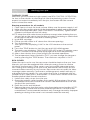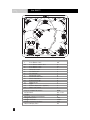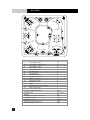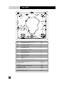
1
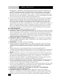
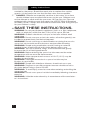
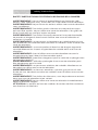
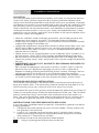
owner’s manual
Please enjoy your new spa, but think safety first. Read your Owner’s Manual
in its entirety before installing your spa and encourage all spa users to do
the same. More than just common sense, this Owner’s Manual provides
vital safety and operational information.
We sincerely hope your spa life is a pleasant experience. If problems should
arise, contact your authorized dealer. Or contact Marquis Corp. at any of the
following:
Email: [email protected]
Web: www.marquisspas.com
Marquis Corp.
596 Hoffman Road
Independence, OR 97351
serial number location
You will find the serial number on the silver tag in the equipment area.
PLEASE FILL OUT AND KEEP FOR FUTURE REFERENCE
Name of Purchaser____________________________________________________
Date of Purchase __________________________________________________
Address ______________________________________________________________
City ____________________________________State _____Zip Code ______________
Signature ___________________________________________________________
Telephone _________________________________________________________
Spa Model/Color ____________________________________________________
Spa Serial # _______________________________________________________
Pack Serial # _______________________________________________________
Dealer’s Name ______________________________________________________
Dealer’s Address __________________________________________________
City ___________________________________State______Zip Code______________
Telephone ___________________________________________________________
Every effort has been made to ensure the accuracy of this manual. However, Marquis Corp. reserves the right to improve its product without notice.
This could create a minor variation between this manual and the actual
product you receive. We apologize for any inconvenience this may cause.
1
owner’s manual index
IMPORTANT SAFETY INSTRUCTIONS
120V, Cord Connected Models ..............................................................2
240V, Permanently Installed or Converted Models ............................2-3
Safety ..........................................................................................................3-7
INSTALLATION INSTRUCTIONS
Location .....................................................................................................8-9
Filter Cartridge ...........................................................................................9
Electrical Requirements ...........................................................................10-11
STARTING YOUR SPA .............................................................................12
SPA SPECIFICATIONS
660 ..............................................................................................................13-14
545...............................................................................................................15-16
530...............................................................................................................17-18
435...............................................................................................................19-20
425...............................................................................................................21-22
322 ..............................................................................................................23-24
SPA CONTROL OPERATION
All Models....................................................................................................25-30
Audio Systems...........................................................................................30-31
EQUIPMENT DIAGRAM
660 and 545...............................................................................................32
530 and 435...............................................................................................33
435 2-pump and 425...............................................................................34
322...............................................................................................................35
TROUBLESHOOTING ...............................................................................36
LCD Diagnostic Messages ......................................................................36-37
MAINTENANCE ..........................................................................................38-43
WARRANTY..................................................................................................44-45
STEREO WARRANTY................................................................................46-47
2
safety instructions
The following instructions contain important safety information. We strongly encourage you to read and apply them.
IMPORTANT SAFETY
INSTRUCTIONS
WHEN INSTALLING AND USING THIS ELECTRICAL EQUIPMENT,
BASIC SAFETY PRECAUTIONS SHOULD ALWAYS BE FOLLOWED,
INCLUDING THE FOLLOWING:
READ AND FOLLOW ALL
INSTRUCTIONS
1. 2. WARNING: To reduce the risk of injury, do not permit children to use this
product unless closely supervised at all times.
3. DANGER: RISK OF CHILD DROWNING. Extreme caution must be exercised to prevent unauthorized access by children. To avoid accidents,
ensure that children cannot use the spa or hot tub unless they are supervised at all times.
120 VOLT, CORD CONNECTED MODELS
4. DANGER: RISK OF INJURY. Connect only to a grounded source.
5. Do not bury the power cord.
6. WARNING: To reduce the risk of electric shock, replace a damaged cord
immediately.
7. A ground terminal (pressure wire connector) is provided on the surface
of the control box inside the equipment compartment. This connector
should be bonded with a minimum No. 8 AWG (8.4mm2) (No. 6 AWG
in Canada) solid copper wire between this unit and any metal ladders,
metal water pipes, metal enclosures of electrical equipment, conduit, or
metal equipment within five feet (1.5m) of the spa. If the spa is located on
a reinforced concrete pad, the reinforced steel should also be bonded to
the ground terminal.
8. WARNING: Your spa may be equipped with a ground fault circuit interrupter (GFCI) on the end of the power supply cord. Before each use
of the spa, with the plug connected to the power supply and the unit
operating, press the “test” button. The unit should stop operating and the
GFCI power indicator will go out. Wait thirty seconds and then reset the
GFCI by pressing the “Reset” button. The GFCI power indicator will turn
on, restoring power to the spa. If the interrupter does not perform in this
manner, it is an indication of an electrical malfunction and the possibility of
an electric shock. Disconnect the plug from the receptacle until the fault
has been identified and corrected.
240 VOLT, PERMANENTLY INSTALLED OR CONVERTED MODELS
9. A ground terminal is provided on the terminal block (TB-1, terminal 7) located inside the control box. To reduce the risk of electric shock, connect this terminal to the grounding terminal of your electrical service or
supply panel with a continuous green, insulated copper wire. The wire
must be equivalent in size to the circuit conductors supplying the
3
safety instructions
equipment. In addition, a bonding terminal (pressure wire connector) is
provided on the outside of the control box for bonding to local ground
points. To reduce the risk of electric shock, this connector should be
bonded with a No. 8 AWG (8.42mm2) (No. 6 AWG in Canada) solid copper wire to any metal ladders, water pipes, or other metal within five feet
(1.5m) of the spa to comply with local requirements.
10. Your spa uses ground fault circuit interrupters in the electrical subpanel.
Before each use of the spa and with the unit operating press the Test
button on each breaker. The switch should click over to the “Trip” position. Wait thirty seconds and reset each GFCI breaker by switching it
completely off and then completely on. The switch should then stay on. If
either of the interrupters does not perform in this manner, it is an indication of an electrical malfunction and the possibility of an electric shock.
Disconnect the power until the fault has been identified and corrected.
ALL SPA MODELS
11.Install the spa so proper drainage is provided.
12.DANGER: RISK OF ELECTRIC SHOCK. Install the spa at least five feet
(1.5m) away from metal surfaces, in accordance with the National Electric
Code ANS/NMFPA70-1993. Each metal surface must be permanently
connected to a minimum No. 8 (8.42mm2) (No. 6 AWG in Canada) solid
copper conductor attached to the wire bonding connector on the terminal box provided for this purpose.
13.DANGER: risk of electric shock. Do not permit any appliance,
such as a light, telephone, radio, or television, etc. within five feet (1.5m)
of the spa or hot tub.
14.WARNING: To reduce the risk of injury:
• Water temperatures between 100°F (38°C) and 104°F (40°C) are considered safe for a healthy adult. Lower water temperatures are recommended for extended use (exceeding 10 minutes) and for young children.
• Since excessive water temperatures have a high potential for causing fetal damage during the early months of pregnancy, pregnant or
possibly pregnant women should limit spa water temperatures to 100°F
(38°C).
• Before entering a spa, the user should measure the water temperature
with an accurate, waterproof, fever thermometer since the tolerance of
temperature-regulating devices may vary as much as +/- 5°F (3°C).
• The use of drugs, alcohol, or medication before or during spa use may
lead to unconsciousness with the possibility of drowning.
• Persons suffering from obesity or with a medical history of heart disease,
low or high blood pressure, circulatory system problems, or diabetes
should consult a physician before using the spa.
• Persons using medications should consult a physician before using a spa
since some medication may induce drowsiness while other medication
may affect heart rate, blood pressure, and circulation.
15.DANGER: TO REDUCE THE RISK OF INJURY TO PERSONS. Do not remove the suction fittings.
16.DANGER: RISK OF INJURY: Never operate a spa if the suction
guard(s) is broken or missing. Never replace a suction guard with one
rated less than the flow rate marked on the original suction guard. The
suction guard(s) in the spa are sized to match the specific water flow
4
safety instructions
created by the pump. Should the need arise to replace the suction
guard(s) or the pump, be sure that the flow rates are compatible.
17. DANGER: Children are especially sensitive to hot water. At no time should children have unsupervised access to the spa. Children must
not be allowed to climb onto the spa cover. All Everyday Hot Tubs are
equipped with a locking cover that meets the ASTM F1346-91 Standard
for Safety Covers. Always lock the child resistant locks after using the spa
for your children’s safety.
SAVE THESE INSTRUCTIONS.
18.
Warning: Do not permit electric appliance (such as a light, telephone, radio, or television) within five feet (1.5m) of this spa or hot tub.
Warning: Children should not use spas or hot tubs without adult supervision.
Warning: Do not use spas or hot tubs unless all suction guard(s) are
installed to prevent body and hair entrapment.
Warning: Do not use drugs or alcohol before or during the use of a
spa or hot tub to avoid unconsciousness and possible drowning.
Warning: People using medications and/or having an adverse medical history should consult a physician before using a spa.
Warning: The use of alcohol, drugs, and medication can greatly increase the risk of fatal hyperthermia.
Warning: Before entering the spa or hot tub measure the water temperature with an accurate thermometer.
Warning: Water temperature in excess of 104°F (40°C) may be injurious to your health.
Warning: Prolonged immersion in a spa or hot tub may be injurious to your health.
Warning: People with infectious diseases should not use a spa.
Warning: Pregnant or possibly pregnant women should consult a physician before using a spa or hot tub.
Warning: To avoid injury, exercise care when entering and exiting the
spa or hot tub.
Warning: Do not use a spa or hot tub immediately following strenuous
exercise.
warning: Maintain water chemistry in accordance with manufacturer’s instructions.
5
safety instructions
safety instructions for French speaking spa owners
Avertissement: Ne pas placer d’appareil électrique (luminaire, téléphone, radio, téléviseur, etc.) moins de 1.52 m de cette cuve de relaxation.
Avertissement: Ne pas laisser les enfants utiliser une cuve de relaxation
sans surveillance.
Avertissement: Pour éviter que les cheveux ou une partie du corps
puissent être aspirés, ne pas utiliser une cuve de relaxation si les grilles de
prise d’aspiration ne sont pas toutes en place.
Avertissement: Pour éviter l’évanouissement et la noyade éventuelle,
ne prendre ni drogue ni alcool avant d’utiliser une cuve de relaxation ni
quand on s’y trouve.
Avertissement: Les personnes qui prennent des médicaments ou ont
des problemès de santé devraient consulter un médecin avant d’utiliser une
cuve de relaxation.
Avertissement: La consommation d/alcool ou de drogue augmente considérablement les risques d’hyperthermie motrelle dans une cuve de
relaxation.
Avertissement: Avant d’utiliser une cuve de relaxation mesurer la température de l’eau l’aide d’un thermométre précis.
Avertissement: Il peut être dangereux pour la santé de se plonger dans
de l’eau plus de 40°C.
Avertissement: L’utilisation prolongée d’une cuve de relaxation peut
être dangereuse pour la santé.
Avertissement: Les personnes atteintes de maladies infectieuses ne
devraient pas utiliser une cuve de relaxation.
Avertissement: Les femmes enceintes, que leur grossesse soit confirmée ou non, devraient consulter un médecin avant d’utiliser une cuve de
relaxation.
Avertissement: Pour éviter des blessures, user de prudence en entrant
dans une cuve de relaxation et en sortant.
Avertissement: Ne pas utiliser une cuve de relaxation immédiatement
aprés un exercice fatigant.
Attention: La tenteur de l’eau en matières dissoutes doit être conforme
aux directives du fabricant.
6
safety instructions
PERSONAL SAFETY
Prolonged immersion in hot water can result in HYPERTHERMIA, a dangerous condition which occurs when the internal temperature of the body
reaches a level above normal (98.6°F, 37°C). The symptoms of hyperthermia include dizziness, fainting, drowsiness, lethargy, and a body temperature
above 98.6°F (37°C). The physical effects of hyperthermia include unawareness of impending hazard, failure to perceive heat, failure to recognize the
need to exit the spa, physical inability to exit the spa, fetal damage in pregnant women, and unconsciousness resulting in a danger of drowning.
WARNING: The use of alcohol, drugs, or medication can greatly increase
the risk of fatal hyperthermia in hot tubs and spas.
Persons taking medications which induce drowsiness such as tranquilizers,
antihistamines, or anticoagulants should not use the spa. Pregnant women
and persons with a medical history of heart disease, diabetes, or high blood
pressure should consult a physician before using the spa.
PERSONAL SAFETY DOs:
• Be sure your spa is connected to the power supply correctly – only use
a licensed electrical contractor.
• Shut off power supply (unplug 120V models) before draining the spa or
servicing the electrical components.
• Test the Ground Fault Circuit Interrupter (GFCI) monthly.
• Always test the water temperature with an accurate thermometer before entering the spa to be sure that it’s a safe temperature.
• Remember that wet surfaces can be very slippery. Take care when entering and exiting the spa.
• Lock the spa cover when the spa is not in use, whether it is empty or full
of water.
• Keep the water clean and sanitized with correct chemical care.
• Turn on the jets when adding ANY chemicals to the spa water.
• Clean the filter cartridge monthly to remove debris and mineral buildup
which affects the performance of the hydrotherapy jets, limits the flow,
or trips the high limit thermostat which will turn off the entire spa.
PERSONAL SAFETY DO NOTs:
• Don’t use the spa with the equipment compartment door removed.
• Don’t use the spa for more than 10 minutes of time at water temperatures in excess of 100°F (38°C).
• Don’t allow the jet pump to operate for an extended period of time with the cover in place. Extended pump operation causes a slow heat
buildup due to water friction. The spa equipment controls are equipped
with a built-in safety timer that automatically shuts off the jet pump after
15 minutes of continuous operation should it have been left on inadvertently.
• Don’t operate the spa at any time with the filter cartridges removed.
• Don’t lift or drag the cover by using the tie-down straps; always lift and
carry by using the external handles.
• Don’t store chemicals in the spa’s equipment compartment.
• Don’t hesitate to call your authorized dealer with any questions or main7 tenance concerns.
installation instructions
LOCATION
For your portable spa to function properly and safely, it must be located on
a hard, flat, level surface. Inground spas require special installation techniques and should be planned in conjunction with your spa dealer. Improper
installation can result in structural damage to the spa and the voiding of your
spa warranty. Items to discuss with your dealer include: local construction
codes; electrical service requirements; serviceability of equipment; present
underground obstructions such as gas, water, and telephone lines; safety
measures such as fences and locks; and visibility of the spa installation from
the home, street, and neighbors.
• Allow for sufficient water drainage around the spa to help preserve the
equipment and support structure. This includes indoor installations.
• A filled spa can weigh in excess of 4,000 pounds and the location should
support the weight of the filled spa.
• Locate the equipment compartment where it will be accessible. Your spa
MUST be installed to permit access for servicing the equipment above
and/or below any decks or floors. Access is essential and must allow adequate room for service.
• Leave access to the circuit breakers in the subpanel (240V models) or to
the interrupter switch (GFCI, 120V models) on the end of the power cord.
• Be sure the spa is level and in the final position BEFORE filling with water.
Check for power cords, tools, and hoses that may be caught underneath
the spa.
• IMPORTANT: DO NOT LET AN EMPTY SPA REMAIN EXPOSED TO
DIRECT SUNLIGHT. Spa surface temperatures can reach in excess of 150°F (65°C) if left exposed to the sun. Significant damage can occur if this is allowed to happen, including warping and blistering of the surface. Damage, that occurs as a result of this exposure is not covered under the warranty.
• CAUTION: Never try to move a spa that has not been fully drained. To do
so could result in damage to the spa and physical injury to the mover.
OUTDOOR AND PATIO INSTALLATION
To install the spa outdoors, we recommend a reinforced concrete pad at
least four inches thick. The reinforcing material should be attached to a #8
AWG bonding wire per national and local electrical code.
If you place the spa on the ground, even temporarily, place the spa empty of
water on concrete pavers under the entire bottom of the spa. The concrete
pavers should be a least two inches thick and level across the entire surface. The spa will inevitably settle and not remain level on this surface, thus
it’s important to get the spa onto a solid foundation as soon as possible.
Instructions for prefabricated spa pads
If you are using a prefabricated spa pad for a foundation, please use the following guidelines:
1. Designate the area where the spa is to be installed. Please make sure
the ground is flat and level.
2. Using 2”x 6” weather resistant lumber and 3” outdoor deck screws,
build a frame large enough for the prefabricated spa pad to fit inside
with minimum 1” clearance on all sides.
3. Install the frame in the area that has been leveled.
8 4. Using crushed gravel, fill the frame to the top.
installation instructions
5. Lay a straight piece of lumber across the frame and level any high spots
in the gravel by pushing the straight lumber across the frame. Fill in any
low areas with more gravel and re-level using the straight piece of lumber.
6. Compact the gravel to make the surface is hard and flat. You may need
to add more gravel to bring the level back up to the top of the frame. If
so, please re-level and re-compact until you have a hard, flat level surface that is even with the top of the frame.
7. Place the prefabricated spa pad on top of the gravel. Be careful not to
disturb the hard, flat, level surface.
8. Make sure no portion of the spa pad is outside or on top of the framing.
9. Place the spa on top of the pad and fill the spa with water.
DECK INSTALLATION
Be sure the deck can support the weight of your filled spa by checking the
deck’s maximum load capacity. Consult a qualified building contractor or
structural engineer. Minimum requirement is 100 pounds per square foot.
INDOOR INSTALLATION
There are special requirements if you place your spa indoors. Flooring material must provide adequate traction when wet. Proper drainage is essential
to prevent water puddling. Proper ventilation to the area is required. The addition of a ventilation system is recommended. See contractor for details.
SHUT-OFF VALVES
Your spa is equipped with shut-off valves (see Equipment Diagram) that
shut off the water flow to the equipment system for dealer service. At times,
a new spa or one that has recently been serviced, may have the shut-off
valves partially closed which can restrict the water flow and hinder jet performance. Be sure the valves are fully open.
FREEZE PROTECTION
When a freeze condition is detected (which occurs when the temperature in
the heater housing drops to 55°F (13°C) the jet pump is automatically activated. In areas with extremely cold winter conditions, your spa should be fine as
long as it is left running at normal operating temperatures. For extra protection see your dealer for an optional freeze sensor. If you plan to turn the spa
off, follow instructions (SUSPENDED USE OR WINTERIZING YOUR SPA).
OVERHEATING
In the case of extended hot weather, the spa water temperature may reach
and maintain 104°F to 106°F (40°C to 41°C) or higher. This is due to the ambient temperature and the full insulation in the spa cabinet. You may have
the option of shortening the pump-run time. See SPA CONTROL OPERATION for available options.
SUCTION GUARDS
The suction guard(s) in the footwell of your spa is an opening through which
the jet pump draws water. Suction fittings are equipped with a safety guard.
Suction through the fittings can be strong. The safety guard(s) must remain
in place and undamaged. A fitting with a damaged guard(s) can be dangerous, especially to small children or people with long hair. Should any part of
the body become drawn to a fitting, turn the jet pump off immediately. Long
hair should be restrained in a bathing cap, never allow it to float freely in the spa. Replace any missing or damaged suction guard(s). NOTE: It is 9
normal for the flow rates of the suction fittings to vary from strong to barely noticeable.
installation instructions
ELECTRICAL REQUIREMENTS
It is the responsibility of the spa owner to ensure that all electrical connections are made by a qualified electrician in accordance with all national,
state, and local electrical codes in effect at the time of installation.
240 Volt
All connections must be made in accordance with the wiring diagram found
on the inside of the control box cover. Connections must be made with
copper conductors only – do NOT use aluminum wire. All conductors, circuit
breakers, and fuses and the GFCI must be sized in accordance to the total
amperage load as specified:
• Permanently connected (Hard wired).
• Rated 240V, 60Hz, 50A, three wires (#6 copper) plus ground (#8 copper),
[4 wires total].
• Circuit breaker or fuse size: 50A.
• A disconnecting means must be installed within sight from the equipment
and at least 5 feet (1.52m) from the inside walls of the spa.
• Connect only to a circuit protected by a Class A Ground Fault Circuit Interrupter (GFCI).
• For units used in other than single-family dwellings, a clearly labeled emergency switch shall be provided as part of the installation. The switch shall be readily accessible to the occupants and shall be installed at
least five feet (1.52 m) away, adjacent to, and within sight of the unit.
• A pressure wire connector is provided on the exterior of the control box
to allow connection of a bonding wire to any metal ladder, metal water pipe, common bonding grid (reinforced concrete slab, ground plate
beneath the spa), or any other metal within 5 feet (1.52 m) of the spa.
The bonding wire shall be copper and at least #8 AWG (8.42mm²), #6 in
Canada.
NOTE: Ensure that a Ground Fault
Circuit Interrupter (GFCI) is properly
installed. Failure to do so may result in
spa malfunction or damage which is not
warranted. GFCIs are available from your
authorized dealer.
120 Volt
120 Volt spas shall be plugged into a properly grounded, grounding type 15
amp receptacle on a dedicated circuit. A dedicated circuit is a circuit with
no other components that consume power, such as lights, televisions, radios, computers, or other electronic devices. These could cause your spa to
malfunction by any of the following: unusual text on the control panel, slow
heating, poor jet action, tripping house breaker, or blown fuses. Failure to
follow these instructions could lead to premature failure of spa components
that would not be covered under the warranty. The dedicated circuit shall
meet the following specifications:
10
installation instructions
• Rated 120V, 60Hz, 15A (2 wires plus ground)
• Circuit breaker or fuse size: 15A
• The receptacle must be at least 5 feet (1.52 m) from the spa.
• The 15 foot GFCI power cord provided with the spa must be plugged
directly into the receptacle. Do NOT use an extension cord or any other adaptor. Actual exposed length of cord will vary by model, but will never
be less than 12 feet.
Convert 120 Volt to 240 Volt
120 Volt spas may be converted to operate on 240V, 50A. All connections
must be made by a licensed electrician.
1.Disconnect the power by unplugging the GFCI power cord from the receptacle. Remove the cord from the terminal block on the circuit board.
2.Locate the white jumper wire on the bottom circuit board at J29 and J33.
Remove this wire and save if the spa ever needs to be converted back to
120 volt.
3.For 50A operation, move dip switch number 2 to the on position.
4.Rated 240V, 60HZ, 50A, three wire (#6 copper) plus ground (#8 copper),
4 wires total.
5.For 30A do not move dip switch number 2.
6.Rated 240V, 60HZ, 30A three wire (#8 copper) plus ground (#10 copper,
4 wires total.
STARTUP PROCEDURE
Your spa is equipped with solid-state controls specific to your spa model.
Please see SPA CONTROL OPERATION.
To start your spa, you will need a water test strip. It is important to follow
each of these steps when starting your spa. Once you have completed the
following steps, refer to the WATER TREATMENT section for proper start-up
water maintenance.
NOTE: Your spa has been filled and test-run at the factory. The first time
your spa is filled with water, some discoloration from residual test water may
appear. This will disappear when the spa is completely filled and the filtration
system is functioning. Test the water for the proper chemical balance and
adjust as necessary. PROPER CHEMICAL BALANCE IS IMPORTANT for
your safety and the longevity of your spa.
11
starting your spa
THERAPY PUMP
Allow the spa to circulate on high-speed (see SPA CONTROL OPERATION)
for four to five minutes to discharge air from the plumbing system. Do not
expect hot water immediately from the jets; the heater will take several
hours to heat the water.
Startup procedure for all models
1. Place spa on a hard, flat, level surface. Make sure the power supply is off.
2. Make sure the suction guard(s) in the footwell are in place and undamaged.
3. Open the equipment door. (SEE EQUIPMENT DIAGRAM). Tighten all disconnects and open all shut-off valves.
NOTE: Keep the drain valve closed at all times except when draining the spa
(do not rely on the cap to stop the flow of water). Not doing so could result
in damage to the drain valve due to freezing water.
4. Install filter cartridge.
5. Fill the spa with water to 3” above the skimmer openings.
6. Turn the power on.
7. Your spa is now displaying “LINK” in the LCD window on the control
panel.
8. Press the TEMP button to start the spa and LINK will disappear.
9. The spa is now displaying “RUN PMPS PURG AIR” in the LCD window, press
the JET 1 button to run the pump and purge the air from the plumbing.
10.After a few minutes the system will go into standard operations.
11.The temperature factory default is 100°F; you can change the temperature by pressing the TEMP button. The maximum set point is 104°F.
SPA COVER
When the spa is not in use, the spa cover should be kept on the spa. Your
Marquis spa must be equipped with a Marquis energy cover to receive
full acrylic shell warranty. Other covers may not provide adequate protection. Fading and staining of the spa cover and broken foam cores are not
covered under warranty for any reason. Spa covers do not qualify for labor
coverage under warranty. Purchase or exchange parts under warranty at
authorized Marquis dealer. For your safety, the cover is equipped with adjustable straps, safety locks, and handles. To avoid stress on the cover and
handles please follow these instructions:
1. Unlock the safety straps from the spa.
2. Grasp the exterior cover handles and carefully lift the edge of the cover.
To facilitate removal first break the vacuum seal between the cover and
the lip of the spa interior.
3. Raise the cover and fold back.
4. Remove the cover from the spa by using the exterior cover handles. NOTE:
When opening a cover with a cover removal mechanism, use one of the
manufacturer’s recommended methods only. Damage caused by improper
opening or closing of the cover is not covered under the warranty.
12
the 660™
13
#
1
1N
2
3
4
5
6
7
8
9
10
11
12
13
14
Component Identification
200 Series Jets
200 Series Neck Jets
300 Series Jets
400 Series Jets
Control Panel
Jet Selectors Air Control
Waterfall Valve
Waterfall features
Filter Canisters
Suction Fittings
Floor Drain
Light
Stereo Speakers (option)
Neck Jet Valve
Physical Specifications
Dimensions
Height
Seating Capacity/Positions
Weight Dry/Lbs.
Weight Full/Lbs.
Water Capacity/Gallons
Total Therapy Jets
Qty.
33
2
21
4
1
2
1
2
2
2
3
1
1
2
1
Size
90” x 90”
34”
6
780
4032
390
60
the 660™ zones
PUMP 2
ZONE 2
PUMP 1
ZONE 2
14
PUMP 2
ZONE 1
PUMP 1
ZONE 1
the 545™
15
#
1
1N
2
3
4
5
6
7
8
9
10
11
12
13
14
Component Identification
200 Series Jets
200 Series Neck Jets
300 Series Jets
400 Series Jets
Control Panel
Jet Selector Air Controls
Waterfall Valve
Waterfall features
Filter Canisters
Suction Fittings
Floor Drain
Light
Stereo Speakers (option)
Neck Jet Valve
Physical Specifications
Dimensions
Height
Seating Capacity/Positions
Weight Dry/Lbs.
Weight Full/Lbs.
Water Capacity/Gallons
Total Therapy Jets
Qty.
27
2
12
4
1
1
2
1
2
2
3
1
1
2
1
Size
84” x 84”
34”
6/6
740
3659
350
45
the 545™ zones
PUMP 2
ZONE 2
PUMP 1
ZONE 2
16
PUMP 1
ZONE 1
the 530™
7
4
13
8
2
3
12
2
1
1
1
1
2
1 1
11
1
1
2
3
9
1
9
2
1
9
5
10
2
2
1
2
2
1
13
1
6
17
#
1
1N
2
3
4
5
6
7
8
9
10
11
12
13
14
2
8
Component Identification
200 Series Jets
200 Series Neck Jets
300 Series Jets
400 Series Jets
Control Panel
Jet Selector Air Controls
Waterfall Valve
Waterfall features
Filter Canisters
Suction Fitting(s)
Floor Drain
Light
Stereo Speakers (option)
Neck Jet Valve
Physical Specifications
Dimensions
Height
Seating Capacity/Positions
Weight Dry/Lbs.
Weight Full/Lbs.
Water Capacity/Gallons
Total Therapy Jets
1
1N
1
1
1N
14
Qty.
16
2
10
2
1
1
2
1
2
2
1
1
1
2
1
Size
84” x 84”
34”
6/6
740
3659
350
30
the 530™ zones
PUMP 2
ZONE A
ZONE B
ZONE A
ZONE B
PUMP 1
18
the 435™
5
1
13
1
1
2
2
2
1
1
2
2
3
3
2
3
3
1
10
1
7
1
2 2
2
13
19
2
2
11
2
2
8
6
13
9
2
12
1N
1
1
10
1N
22
6
1
1
14
1
4
#
Component Identification
1
200 Series Jets
1N
200 Series Neck Jets
2
300 Series Jets
3
400 Series Jets
4
Control Panel
5
Jet Selector (option)
6
Air Control
7
Waterfall Valve
8
Waterfall Feature
9
Filter Canister
10
Suction Fittings
11
Floor Drain
12
Light
13
Stereo Speakers (option)
Physical Specifications
Dimensions
Height
Seating Capacity/Positions
Weight Dry/Lbs.
Weight Full/Lbs.
Water Capacity/Gallons
Total Therapy Jets
Qty.
13
2
16
4
1
1
2
1
1
1
2
1
1
2
Size
77” x 77”
34”
4/5
500
3085
310
35
the 435™ zones
ZONE 2*
ZONE 1*
*Jet selector is optional
16
20
the 425™
21
#
Component Identification
1
200 Series Jets
1N
200 Series Neck Jets
2
300 Series Jets
3
400 Series Jets
4
Control Panel
5
Jet Selector (option)
6
Air Control
7
Waterfall Valve
8
Waterfall Feature
9
Filter Canister
10
Suction Fittings
11
Floor Drain
12
Light
13
Stereo Speakers (option)
Physical Specifications
Dimensions
Height
Seating Capacity/Positions
Weight Dry/Lbs.
Weight Full/Lbs.
Water Capacity/Gallons
Total Therapy Jets
Qty.
10
2
11
2
1
1
2
1
1
1
2
1
1
2
Size
77” x 77”
29.5”
4/5
475
2977
300
25
the 425™ zones
ZONE 1
ZONE 2
16
22
the 322™
13
4
6
13
12
2
2
1
1
1 1
9
10
7
8
14
11
1
1
5
3
2
2
2
2
2
2
1
2
1
3
2
1
2
23
#
Component Identification
1
200 Series Jets
2
300 Series Jets
3
400 Series Jets
4
Control Panel
5
Jet Selector
6
Air Control
7
Waterfall Valve
8
Waterfall Feature
9
Filter Canister
10
Suction Fitting
11
Floor Drain
12
Light
13
Stereo Speakers (option)
Physical Specifications
Dimensions
Height
Seating Capacity/Positions
Weight Dry/Lbs.
Weight Full/Lbs.
Water Capacity/Gallons
Total Therapy Jets
Qty.
9
11
2
1
1
1
2
1
1
1
1
1
2
Size
60” x 84”
29.5”
3/4
400
2026
195
22
the 322™ zones
ZONE 2
ZONE 1
16
24
spa control operation
system controls
Start-up
1. At initial power up, the LCD display on the panel will flash “LINK”. Press
any on the buttons on the control panel to link the panel to the control
box and remove the “LINK” message from the display.
2. “RUN PMPS PURG AIR -- -- -- --” will be displayed on the panel. This is an
opportunity to run the pumps and purge any air from the system and associated plumbing lines. This period will last 4-5 minutes or can be exited
by pressing the Temp +/- button.
3. “SET TIME” will be displayed on the panel window. To enter the time,
press the listed buttons in the following sequence. Button presses must
occur within 3-5 seconds of each other.
a. Temp +/ b. Light: Press until you see “TIME” displayed in the LCD display on the panel.
c. Temp +/- To display clock
d. Temp +/- To adjust hour (note the AM – PM indicator in the display)
e. Light: To move to minutes
f. Temp +/- To adjust minutes
g. Light: To hold and exit or wait 10 seconds for automatic exiting
Note: In the event of a power interruption/loss, the start-up sequence
will need to be repeated.
Operating the spa
Jets 1
Press Jets 1 button to turn on pump one to low speed. Pressing a second
time will turn the pump on to high speed. Pressing a third time will turn the
pump off. The high speed of pump 1 will run for 15 minutes and then switch
to low speed. Once on low speed, the pump will run for 15 minutes and
then shut off. The high and low speed operation will stop after 15 minutes of
use. If the system is in a filter cycle or calling for heat, low speed will continue to run. To restart the pump, press the Jets 1 button.” The yellow LED
indictor under the LCD display will illuminate anytime the pump is running.
25
spa control operation
Jets 2 (Two Pump Models Only)
Press Jets 2 button to turn on pump two high speed. Pressing a second
time will turn the pump off. The high speed of pump 2 will run for 15 minutes
and then turn off. To restart the pump, press the Jets 2 button.
Adjusting temperature (factory default 100° F)
To adjust the temperature of the water, press the Temp +/ – button. The
display always shows actual water temperature. The first press of the button will display the set temperature and begin to flash. Continue to press or
hold the Temp +/ – to reach the desired set temperature. Once the display
stops blinking the new temperature setting will be set. The factory default
setting is 100° F (38° C). The minimum temperature that can be set is 80° F
(27° C) and the maximum temperature that can be set is 104° F (40° C). If
a lower set temperature is desired, see User Programming section – Dual
Temperature Range.
Soak
Pressing the Soak button will turn off all pump operation. This is a useful feature when soaking in the hot water with no jets running is desired. The Soak
feature will last 60 minutes and then resume normal operation. Pressing
any jet button will override the soak feature and turn on the pumps or you
can simply press the Soak button to exit the mode. Turning the LED lights
on and off will not affect the quite soak mode. The yellow LED indictor light
under the LCD display will illuminate anytime this feature is engaged.
Note: If the system is heating it will take a few moments for the Quiet Soak
feature to engage.
Timer
Press the Timer button to start the timer. The display will start at E00 and
begin timing how long you have been in the spa or using a certain feature.
“E” is for elapsed and the two trailing characters track time in one minute
intervals. The display will alternate with the current water temperature every
10 seconds. The timer will continue to run up to 60 minutes. To turn off,
press the Timer button one time. The yellow LED indictor below the LCD
display will illuminate anytime this feature is running.
Light
Press the Light button to turn the interior spa lights on and off. Pressing
the button repeatedly (within 2-3 seconds of each press) will allow for color
scrolling of the LED lights. If left on the lights will run for 60 minutes and then
turn off automatically.
User programming
The following features allow for additional control and setting of the onboard electronics. In most cases the factory default settings are adequate
for normal use and operation. To access any of the following features press
Temp +/- and then Light: then scroll through the features by continuing to
press the Light button.
26
spa control operation
You exit the programming mode at any time by continuing to press the Light
button until you arrive back at the temperature display or by simply pausing
for 10 to 20 seconds.
Dual Temperature Range (Factory default “Range p" recommended)
The system supports the choice of two temperature ranges for controlling
heat. This feature can be useful if you plan on being gone for an extended
period of time or anticipate infrequent use of the spa. The temperature
range indicator is located on the bottom half of the LCD display and will be
shown as “Range p” for high range or “Range q” for low range. The default
temperature range, or high range, is 80° F (27° C) to 104° F (40° C). The
optional low range is 55° F (13° C) to 80° F (27° C). To change the range
setting, press the listed buttons in the following sequence. Button presses
must occur within 3-5 seconds of each other.
1. Temp +/2.Light – until “TEMP” is displayed in the LCD window
3.Temp +/- to change range setting to p for high or q for low.
4.Light – to select and exit. To return the display to the original position, follow the same sequence.
Mode (Ready mode is factory default - recommended)
This feature can be used for periods of when you are planning on being
gone for an extended amount of time and don’t want the spa running
more regularly. Putting the unit in “Ready” mode will ensure the spa is at
full temperature and ready for use at any time. Putting the unit in “Rest”
mode will only allow the spa to heat during a scheduled filtration cycle. To
access and change the mode, press the listed buttons in the following
sequence. Button presses must occur within 3-5 seconds of each
1. Temp +/2.Light: Press until “MODE” appears in the LCD display
3.Temp +/- To toggle between ready and rest options. The options will appear in the bottom of the LCD display in small print
4.Light: To select and exit
Time
Use this function to reset or change the internal time clock. Note that
this feature is not an actual clock that will display on the panel. The clock
feature is used as a basis for running filter cycles during the correct time of
the day. To set or adjust the clock, press the listed buttons in the following
sequence. Button presses must occur within 3-5 seconds of each other.
1. Temp +/2.Light: Press until you see “TIME” displayed in the LCD display on the
panel.
3.Temp +/- To display clock
4.Temp +/- To adjust hour (note the AM – PM indicator in the display)
5.Light: To move to minutes
6.Temp +/- To adjust minutes
7.Light: To hold and exit
27
spa control operation
“FLIP” (Invert Display)
Your spa will come preset from the factory with the display viewable from
inside the spa (recommended). The system will allow the LCD display on
the panel to invert or “FLIP” to allow reading the display from outside of the
spa if desired. To “FLIP” the display, press the listed buttons in the following
sequence. Button presses must occur within 3-5 seconds of each other.
1.Temp +/2.Light: Until the word “FLIP” appears in the LCD
3.Temp +/- to invert the display
4.Light: To select and exit
To return the display to the original position, follow the same sequence
Temperature Lock or Panel Lock (Unlocked is the factory default Recommended)
The electronic controls can be locked in two levels, temperature lock and
panel lock. Temperature lock will lock the temperature control/button only.
Panel lock will lock all of the controls and buttons on the panel. These
choices can be a useful feature to keep others from accidentally changing
the settings or operating functions available through the control panel. To
engage temperature lock, press the listed buttons in the following sequence. Button presses must occur within 3-5 seconds of each other.
1.Temp +/2.Light: Until you see the word “LOCK” in the LCD display
3.Temp +/- Which will display “TEMP” on the first press. Continue pressing
to change between on and off
4.Light: To select and exit
To engage panel lock, press the listed buttons in the following sequence.
Button presses must occur within 3-5 seconds of each other.
1.Temp +/2.Light: Press until you see the word “LOCK” in the LCD display
3.Temp +/- to enter the menu, “TEMP” will be displayed
4.Light: To display “PANL” in LCD display
5.Temp +/- to display on/off choice
6.Light: To select and exit
To unlock either temperature or panel lock feature, use the following directions.
1.Press and hold down the Temp +/- button
2.While holding down the Temp +/- button, press the Light button two (2)
times
3.The LCD display will read “UNLK” restoring the panel buttons to full operation.
Hold
This is a feature that can be used while servicing your spa such as cleaning the spa shell or the filter. The Soak button on the panel can also
perform the same function. If you choose to use the Hold mode, press
the listed buttons in the following sequence. Button presses must occur
within 3-5 seconds of each other.
28
spa control operation
1. Temp +/2. Light: Press until you see “HOLD” in the LCD display.
3. Temp +/- to engage the hold mode. The panel will scroll “HOLD – ING – FOR
– 0:60” and continue to count down. LCD display will read “DONE”
4. Light: To stop and exit the hold mode at any time. LCD display will read
“DONE”
Filtration Cycles (Factory default is 2 hours one time per day)
The electronic controls will allow for additional control for up to two independent filtration cycles to be set. This can be useful if your usage patterns vary
from light to heavy and/or you need more or less filtration time to aid in maintaining clean water. To adjust the filtration times, press the listed buttons in
the following sequence. Button presses must occur within 3-5 seconds of
each other.
1. Temp +/2. Light: Press until you see the word “FLTR” with a small “1” in the LCD screen
3. Temp +/- Which will change display to “BEGN”. This will be when the cycle
starts during the day or night.
4. Temp +/- To show time. Continue to press to adjust the hour in one hour
intervals
5. Light: To change the display to minutes
6. Temp +/- To change minutes in increments of 15 intervals
7. Light: To set and move to next screen which will be “RUN HRS”. This is how
long the cycle will run.
8. Temp +/- To choose the number of hours you want the spa to filter in one
hour intervals
9. Light: To change the display to minutes
10.Temp +/- To choose the number of minutes you want the spa to filter in 15
minute intervals.
11.Light: To set and show end time. This will be displayed in the LCD window
as “F 1 – ENDS – TIME”
12.Light: To move on to filter cycle 2 which will be displayed in the LCD window
as “FLTR” with a small “2”.
13.Temp +/- to choose on or off. If on is chosen, repeat steps 3 through 11 to
set filter cycle 2.
14.Light: To exit.
Light Timer (Factory default is off – Recommended)
The LED spa lights can be set to come on and go off at specified times
during the day or night. To set the light timer, press the listed buttons in the
following sequence. Button presses must occur within 3-5 seconds of each
other.
1. Temp +/2. Light: Press until you see the word “LITE TIMR” in the LCD display
3. Temp +/- To toggle between on and off
4. Light: To set and change the display to “BEGN” This is when the timer will
start.
29
spa control operation
5. Temp +/- To display hour window and change hour in increments of 1 hour
intervals
6. Light: To set and move to next screen which will be minutes.
7. Temp +/- To choose the number of minutes to run in 15 minute intervals.
8. Light: To set and display “RUN HRS” This is how long the timer will run.
9. Temp +/- To display hour window and change hours to run in 1 hour increments.
10.Light: To set and show minutes
11.Temp +/- to choose minutes of operation in 15 minutes intervals.
12.Light: To set, LCD display will show “TIMR – ENDS – XX:XX” XX:XX being the
time the light will turn off.
13.Temp +/- to exit the mode
Preferences
Fahrenheit or Celsius to be displayed on the LCD panel (F is the default)
1. Temp +/2. Light: Press until you see “PREF” in the LCD screen
3. Temp +/- Which will show F/C in the LCD display
4. Temp +/- To toggle between F (Fahrenheit) or C (Celsius)
5. Light: To set and exit
24 hour or 12 hour clock. (12 hour is the default)
1. Temp +/2. Light: Press until you see “PREF” in the LCD screen
3. Temp +/- Which will show “24-12” in the LCD display
4. Temp +/- To toggle between 24HR and 12HR
5. Light: To set and exit
Clean-Up Cycle (0 to 4 hour choice – factory default 1 hour)
1. Temp +/2. Light: Press until you see “PREF” in the LCD screen
3. Temp +/- Which will show “CLN-- UP” in the LCD display
4. Temp +/- To toggle between 0 (Off) and up to 4 hours in 30 minute intervals
5. Light: To set and exit
Utilities
The information listed in the Utilities section is system information only.
These are features normally used for service technicians and should not
need to be accessed by the consumer.
AUDIO SYSTEM
Please refer to the manufacturer’s owner’s manual for features, operation,
and troubleshooting.
NOTE: Avoid water splashing on the stereo face. Never insert a disk or
operate the stereo with wet hands. Moisture can damage internal components. Water intrusion into stereo is not covered under warranty. See manufacturer’s owner’s manual for coverage information. Consult your Limited
Warranty for more information about coverage.
30
spa control operation
Speakers
Gently push the top of the self-rising speakers to raise them. Hold the
speaker top, avoiding the speaker screens, and gradually rotate the speakers as desired. To lower the speakers gently push the speaker top until it
is completely closed. Make sure speakers are in the down position before
closing the spa cover. Speaker lift mechanism is manufacturer-warranted
against failure to lift due to manufacturing defects only. Closing the spa
cover with speakers in the up position or forcing the speaker down too rapidly can result in damage.
• CAUTION - Risk of Electric Shock. Do not leave compartment door open.
• CAUTION - Risk of Electric Shock. Replace components only with identical components.
• Do not operate the audio controls while inside the spa.
• WARNING – Prevent Electrocution. Do not connect any auxiliary components (for example, cable, additional speakers, headphones, additional
audio/video components, etc.) to the system, except as provided by the
following: The 3.5 mm auxiliary jack is designed for input only from devices
such as an MP3 player operating at 4.5 V or less.
• These units are not provided with an outdoor antennae; it should be installed
in accordance with Article 810 of the National Electrical Code, ANSI/NFPA 70.
• Do not service this product yourself as opening or removing covers may expose you to dangerous voltage or other risk of injury. Refer all servicing
to qualified service personnel.
• If the power supply connections or power supply cord(s) are damaged;
if water is entering the audio compartment or any electrical equipment
compartment area; if the protective shields or barriers are showing signs
of deterioration; or if there are signs of other potential damage to the unit,
turn off the unit and refer servicing to a qualified service personnel.
• This unit should be subjected to periodic routine maintenance (i.e. once
every three months) to make sure that the unit is operating properly.
Audio Expansion Port
The built-in audio expansion port allows you to connect optional accessories. Use the supplied 3.5 cm cord to attach MP3 player. NOTE: The 3.5 cm
auxiliary jack is designed for input only from devices such as an MP3 player
operating at 4.5V or less.
Tempo Audio System
This system will support a wide range of personal audio players with 3.5mm
jacks operating at 4.5V or less. Typically this would be the headphone jack
on the device. To use, pull on the recessed handle of the device drawer that
is located on the door of the spa. Once fully extended, open the lid of the
drawer exposing the supplied 3.5mm cable and plug in the personal audio
player. Song selection, volume, and tone are controlled by the personal
audio device. Once the unit is playing, stow the personal audio device in the
drawer, close the lid and push the drawer back in place. This will ensure the
personal audio device is protected during use.
31
equipment diagram
MODEL 660
10
11
12
13
9
14
4
5
4
2
5
15
1
3
6
7
8
6
MODEL 545
10
11
9
4
12
13
14
5
5
1
3
2
6
4
7
6
8
#Component Qty.
1
Control box and heater 1
2 two-speed pump 1
3 one-speed pump 1
4 Slice valves 2
5 Pump unions 4
6 Pump plugs 2
7 Motor mounts 8
8 Hose bib drain 1
9 Light bulb 1
10 Ozone fitting 1
11 Check valve 1
12 Ozonator 1
13 Stereo power supply (optional) 1
14 Stereo MP3 plug (optional) 1
15 Stereo head unit (optional) 1
32
15
equipment diagram
MODEL 530
10
11
12
9
4
13
14
5
4
1
15
2
8
6
7
MODEL 435
11
13
10
12
14
9
15
5
4
1
2
8
6
7
#Component Qty.
1
Control box and heater 1
2 Two-speed pump 1
4 Slice valves 2
5 Pump unions 2
6 Pump plug 1
7 Motor mounts 4
8 Hose bib drain 1
9 Light bulb 1
10 Ozonator fitting 1
11 Check valve 1
12 Ozonator 1
13 Stereo power supply (optional) 1
14 Stereo MP3 plug (optional) 1
15 Stereo head unit (optional) 1
33
equipment diagram
MODEL 435 2-PUMP
11
13
14
12
4
9
15
4
5
5
1
3
2
6
10
8
6
7
MODEL 425
11
13
10
12
14
9
15
5
4
1
2
8
6
7
#Component Qty.
1
Control box and heater 1
2 Two-speed pump 1
3 Slice valves 2
4 GFCI 1
5 Pump unions 2
6 Pump plug 1
7 Motor mounts 4
8 Light bulb 1
9 Hose bib drain 1
10 Ozonator fitting 1
11 Ozonator 1
12 Check valve 1
13 Stereo power supply (optional) 1
14 Stereo MP3 plug (optional) 1
15 Stereo head unit (optional) 1
34
equipment diagram
MODEL 322
#Component Qty.
1
Control box and heater 1
2 Two-speed pump 1
3 Slice valves 2
4 GFCI 1
5 Pump unions 2
6 Pump plug 1
7 Motor mounts 4
8 Light bulb 1
9 Hose bib drain 1
10 Ozonator fitting 1
11 Ozonator 1
12 Check valve 1
13 Stereo power supply (optional) 1
14 Stereo MP3 plug (optional) 1
15 Stereo head unit (optional) 1
35
troubleshooting guide
PLEASE NOTE: The following corrective actions may be performed by the
spa owner. If the trouble cannot be corrected in the steps below, please
contact your authorized dealer for service. (Improper servicing by an unauthorized service provider or spa owner could result in damage not covered
by the warranty and could cause serious injury.)
EQUIPMENT WILL NOT OPERATE
• Check the control panel LCD window for diagnostic code.
• 240V Spas: Check the circuit breaker on the main circuit panel.
• 120V Spas: Check the GFCI power cord and reset if necessary (see Important Safety Instructions at beginning of manual).
• Check the condition of the power cord.
INADEQUATE JET ACTION
• Be sure the shut-off valves are completely open. • Open the jets by turning the jet face to allow for maximum water flow. • Check for obstruction or restrictions at suction guard(s) or filters, such as
leaves, etc.
• Check to ensure water is at proper level and add water if needed.
NO HEAT
• Check temperature displayed in the LCD window for desired temperature
setting.
• Inspect the filter cartridge for dirt and debris.
• Check that the water is at proper level, 3” above skimmer opening.
• Check to make sure spa is in High Range. Check page 27 for programming the temperature range.
• Lower ambient temperatures may result in heat loss.
NOTE: Do not expect instant hot water from the jets. It will take the heater
12-24 hours to heat the water to the temperature you desire.
LIGHT DOES NOT WORK
• Press the light pad on the control panel.
• Reposition the light bulb in the socket. (See REPLACING LIGHT BULB.)
LCD DIAGNOSTIC MESSAGES
The advanced technology built into the spa allows it to perform a number
of self-diagnostic system checks and it can display a variety of messages in
the LCD window on the control panel.
TOO COLD: Freeze protection has been activated and no correction action
is required. This normal on a fresh fill.
WATR TOO HOT: One of the sensors has reached 110°F. Do not enter the
water; contact your dealer for service.
HTR FLOW LOSS: There is not enough water flow through the heater. Clean
or install new filter(s) and check that the slice valves or fully open. Call dealer
for service.
36
troubleshooting guide
HTR MAY BE DRY: There is little to no water flow through the heater. Check
that the slice valves are fully open. Contact dealer for service.
HTR TOO HOT: One of the sensors has reached 118°F. Do not enter the water. Contact dealer for service.
PRES BTTN TO RSET: Some codes require a button press or power to be
removed and restored.
SNSR BAL-- ANCE: The sensors are reading a temperature of 2°F or more.
This can occur on a fresh fill, no corrective action required. Contact dealer
for service.
SNSR A: Sensor A is non-functional. Contact dealer for service.
SNSR B: Sensor B is non-functional. Contact dealer for service.
MEM FAIL: There is a problem with the firmware. Contact dealer for service.
MEM RSET: Memory has failed. Contact dealer for service.
CLOK FAIL: Clock has failed. Contact dealer for service.
CNFG FAIL: Contact dealer for service.
STUK PUMP: Water may be overheated (DO NOT ENTER THE WATER).
Contact dealer for service.
HOT FALT: A pump may be stuck on. Contact dealer for service.
CHEK PH: Maintenance reminder to check the water pH. Comes up every 7
days, press any button to reset.
CHEK CHEM: Maintenance reminder to check the water sanitizer level.
Comes up every 7 days, press any button to reset.
CLN FLTR: Maintenance reminder to clean the filter. Comes up every 30
days, press any button to reset.
CHNG WATR: Maintenance reminder to change the water. Comes up every
90 days, press any button to reset.
CLN COVR: Maintenance reminder to clean the cover. Comes up every 180
days, press any button to reset.
CHNG FLTR: Maintenance reminder to change the filter. Comes up every
365 days, press any button to reset.
37
maintenance
WEEKLY MAINTENANCE
1.Removing Debris
Remove any debris from the Vortex skimmer and suction guard(s) on
the inside of the spa. Blocked intakes can impede the flow of water
through the jetting system.
2. Water Level
Replenish the water level if necessary so that it is approximately twothirds up the Vortex skimmer opening. (See STARTING YOUR SPA.)
MONTHLY MAINTENANCE
1. Filter Care
We cannot stress enough the importance of a clean filter for proper
water filtration. Dirty filters can restrict water flow, cause hazy water,
and prevent your chemicals from working properly. Many water treatment products clear or clarify the water by clumping microscopic
particles and minerals together so that these larger particles can be
effectively trapped in the filter. A filter clogged with debris and calcium
deposits does not trap particles properly.
The Maintenance Reminder on the control panel indicates a CL every
30 days to remind you to clean your filter.
EVERY three to four MONTHS
Draining and Filling the Spa
The average spa needs to be drained every three to four months. After months of continually adding chemicals to the water and introducing
body oils and lotions, the water can be difficult to manage and chemicals
are not as effective as usual. You may also notice excessive foaming. A
maintenance reminder appears on the control panel as “CHNG WATR”
to remind you to change water. More frequent draining may be required
depending on use.
38
maintenance
1.Leakage Detection
Open the equipment door and check for signs of water leakage around
the pump. Pump seals wear out over time, especially with improper
water chemistry. Early detection of pump seal failure can significantly
reduce repair costs.
2.Ozonator Operation
The ozonator functions whenever the system is running on filter or
clean up cycles. Check to see if the bulb is lighted. The end cap of the
ozonator should glow if functioning properly. If not, the bulb has burned
out. Contact your dealer for service.
3.Draining the Spa
A. Turn off the power to the spa.
B. Open the equipment compartment (see EQUIPMENT DIAGRAM). Remove the hose bib cap from the connection and attach a hose.
C. Open the drain valve. Gravity causes the water to drain out of the
hose.
D. When the spa is empty, close the drain valve and remove the hose. Reinstall the hose bib plug.
NOTE: Keep the drain valve closed at all times except when draining
the spa (do not rely on the cap to stop the flow of water). Not doing so
could result in damage to the drain valve due to freezing water.
AS NEEDED MAINTENANCE
1.Cover Care
Proper care of the cover increases the cover life. Note: Do not use
regular household products or products that contain silicone, alcohol,
steel wool, or bleach.
2.Synthetic Exterior
Clean the exterior of the spa with a mild soap and water solution.
Cleaners containing alcohol, Acetone, Nitrobenzene, and Cyclohexanol
can dissolve and discolor the synthetic exterior.
4.Clean the Acrylic Interior
Once the spa is drained, clean the acrylic interior thoroughly – especially
at the water line. Bleach (diluted) is the recommended cleaning agent
for acrylic – other products should be avoided except as stated below.
To maintain the high gloss of the acrylic surface just follow these simple
steps: For normal care and cleaning use a soft cloth or sponge and
water. Rinse well and dry with a soft, clean cloth. Never use abrasive
cleaners. Do not allow your acrylic surface to come into contact with
products such as ketones or esters such as acetone or ethyl acetate
(nail polish remover), Wintergreen oil (methyl salicylate), nail polish, dry
cleaning solution or other chlorinated organic solvents, lacquer thinners,
gasoline, aromatic solvents, citrus cleaners, pine oil, etc. Remove dust
and dry dirt with a soft, damp cloth. Clean grease, oil, paint and ink
stains with diluted isopropyl (rubbing) alcohol (do not let alcohol pool or
remain on acrylic). Dry with a clean, soft cloth. Avoid using razor blades
or other sharp instruments that might scratch the surface.
39
NOTE: Due to the high-gloss, fine finish of the acrylics, imperfections
in the surface texture may occur. A natural aging process in acrylic can
lead to a process called crazing. Fine spider web-like lines can form on
the cosmetic surface of acrylic over time after exposure to the elements and chemicals. Crazing represents no structural weakening
of acrylic and is not covered under the warranty. Fading, staining and
discoloration may also occur but represent no structural degradation
and are not covered under warranty.
maintenance
NOTE: Do not leave an empty spa uncovered. Direct sunlight on the
spa surface can cause severe damage or blemishing and cause fittings
to discolor and can result in the voiding of any surface warranties.
5.Excess Debris
Grit and debris tracked into the spa should be removed with a spa
vacuum.
6.Water Line
To avoid buildup of oils and lotions at the water line, clean the interior
when needed. We suggest the Glove Sponge to clean without scratching. Note: Do not use the same brush or sponge to clean the exterior
of the spa and the interior of the spa. Soap and other product residue
used on the outside of the spa can cause foaming of the spa water
and scratches to the spa surface.
6. Light Bulb Replacement
A. Turn off the power to the spa.
B. Remove the equipment area door to find the light access. (See
EQUIPMENT DIAGRAM.)
C. Remove the lamp socket from the back of the light assembly by
turning counterclockwise and pulling at the same time.
SUSPENDED USE OR WINTERIZING THE SPA
If you decide to discontinue the use of your spa for any extended period
of time, we suggest you follow the steps below.
NOTE: During long periods of inactivity, damage can occur to equipment
from condensation within the equipment compartment.
1. Turn off the power to the spa.
2. Drain the spa. (See DRAINING AND REFILLING THE SPA.)
3. Remove all residual water from the seating and footwell. If necessary, bail out the remaining water then dry the spa with towels. A
wet/dry vacuum is recommended for best results.
4. Using the wet/dry vacuum, place vacuum nozzle over each jet
nozzle to remove water from plumbing lines, starting with the highest jet and finishing with the lowest jet.
5. Unscrew the pump plug from the pump. (See STARTING YOUR
SPA.)
6. Again, using the wet/dry vacuum, place nozzle over the exposed
pump opening to remove excess water. The pump should be removed from the spa and stored in a climate-controlled room.
7. Clean the spa interior.
8. Clean the filter cartridge.
9. Reinstall the spa cover and lock in place.
NOTE: Direct sunlight on the spa surface can cause severe damage or blemishing and can result in the voiding of any surface warranties.
40
maintenance
Important Chemical Safety Procedures
1. Always keep chemicals out of reach of children.
2. Read product labels carefully prior to use.
3. When dissolving, always add chemicals to water, do not add water to
chemicals. Some dry chemicals should be dissolved prior to adding
them to the spa. Using a clean container, dip some water from the
spa. Mix until dissolved, then add to circulating water.
4. CAUTION: Do not mix chemicals together. Add them separately to
the spa water.
5. All chemical products should be stored in a cool, dry, well-ventilated
area where the average temperature does not exceed 90°F (32°C).
Keep storage area clean of debris such as rags, newspaper, and combustible materials.
6. Keep chemicals away from open flame or other heat source. Do not
smoke near chemicals. If a dry chlorine chemical fire should occur, use
water only. Do not use a dry chemical fire extinguisher to attempt to
put out the fire.
7. When adding chemicals, always keep the water circulating in the spa
with jets in a downward circular pattern for better chemical distribution.
Add chemicals to the spa water one at a time. Allow several minutes
between any new chemical additions using the jet action to evenly
distribute throughout the spa.
8. After adding chemicals, wait the amount of time recommended on
the chemical container before retesting your water for an accurate reading. Retest your spa water before using.
9. If you have any questions or concerns about the correct procedures
for handling chemicals, please contact your authorized dealer.
WATER CARE
There are three things necessary for clean safe water:
1. CIRCULATE: Water has to be circulated regularly; it can not be
stagnant.
2. FILTER: Water has to be filtered to remove particulate and debris.
3. SANITIZE: Water has to be sanitized to kill organisms like algae,
bacteria and virus.
The control system in your spa will automatically circulate and filter. (See
Spa Control Operation.) The sanitation requires minimal effort if
done consistently and properly.
To sanitize spa water, three things are required:
1. BALANCE: The water must be balanced so the sanitizer can work and
spa equipment is protected.
2. SHOCK: Shock to oxidize organics and maximize sanitizer efficiency.
3. SANITIZE: Maintain a proper level of sanitizer at all times.
41
maintenance
WATER CARE TROUBLESHOOTING
P: Problem
S: Solution
Cloudy Water
P: Inadequate filtration or dirty filter.
S: Ensure that the filter is securely installed. Clean or replace filter.
Increase the length of clean up and/or filter cycles.
P: Water is not balanced.
S: Test water and adjust pH, alkalinity, and sanitizer as needed. Shock
to oxidize and destroy organics in the water.
P: Unfiltered particles or chemically saturated.
S: Use Water Clarifier to combine particles.
P: High total dissolved solids
S: Drain, clean, and refill the spa.
Chemical Odor
P: Too many chloramines/bromamines in the water.
S: Treat water with Spa Shock then adjust sanitizer level as necessary.
P: Dull looking water, difficult to manage. High total dissolved solids
(TDS) may be the cause.
S: Drain and refill with fresh water.
Musty Odor
P: Not enough sanitizer in water – bacteria or algae in water.
S: Add sanitizer as necessary and shock. Readjust sanitizer level if necessary.
Yellow Water
P: Low pH and/or low alkalinity.
S: Test and adjust pH with pH and Alkalinity Up. Adjust alkalinity if necessary.
Foaming
P: High concentration of body oils, lotions or soaps, as well as excessive organics.
S: Use Spa Defoamer and adjust pH and sanitizer as needed.
Scum Line in Spa
P: Body oils and dirt.
S: Use Glove Sponge to clean the spa. Test and adjust the sanitizer and
pH if necessary. Increase the clean up cycle.
No Sanitizer Reading
P: Sanitizer level is too low.
S: Shock until the sanitizer registers in the recommended range.
P: Test strip remains “white” even after sanitizer has been added.
S: Sanitizer level could be extremely high. It can bleach the reagents on
42
maintenance
the test strip and give a false reading. Remove spa cover and activate
jets and air control. Allow jets to run for 30 minutes. Test water to see if
desired level has been reached.
High Sanitizer Reading
P:Too much chlorine or bromine added or dispensed into the spa.
S: Remove spa cover and activate jets and air control. Allow jets to run
for 30 minutes. Test water to see if desired level has been reached. Reduce bromine level.
Eye or Skin Irritation
P:Contaminants or excessive amount of chloramines/bromamines in
water.
S: Treat water with Spa Shock. Adjust sanitizer level.
P:pH is low.
S: Adjust as needed.
Corrosion of Metal
P:Low pH.
S: Adjust pH with pH and Alkalinity Up.
Green Water/Algae
P:Low sanitizer level or high pH.
S: Adjust pH and shock as necessary.
Erratic pH
P: Alkalinity and/or calcium hardness are too low causing pH “bounce”.
S: Test and adjust alkalinity and/or calcium hardness to bring them into the ideal range.
43
limited warranty
WHAT THE MARQUIS CORP. LIMITED WARRANTY COVERS
Marquis Corp. warrants that our products will be free from defects in materials
and workmanship for the term set forth exclusively in this warranty. Accessories
purchased from Marquis Corp. or a Marquis Corp. authorized dealer and added to
the spa after manufacture of the spa are not covered under this warranty but may
have other warranties. Refer to owner’s manual for proper use, maintenance and
installation of your spa. The Limited Warranty is made only to the original purchaser of
the spa and is not transferable.
[5] STRUCTURE: The fiber glass structure is warranted for five years not to leak.
Fittings and attachments are not included.
[2] SURFACE: The acrylic surface is warranted for two years against blisters, cracks
and delamination.
[2] PLUMBING: Plumbing and fittings are warranted against water loss for two
years. Warranty coverage does not include gaskets or seals.
[2] EQUIPMENT: Electronic equipment is warranted against defects in materials and
workmanship for two years. Equipment includes equipment packs, PC boards,
pumps, control panels, heater and heat sensors.
[1] EXTERIOR: The synthetic skirt exterior is warranted against cracking and peeling
for one year.
[1] COMPONENTS: The ozonator and GFCI are warranted against defects in
material and workmanship for one year.
[1] PARTS: LED lights, remote controls, valves, spa cover, stereo components, jet
inserts and overlays are warranted for one year. These parts do not qualify
for labor coverage under this warranty. Fuses, non-LED lights, filter, filter lid,
cushioned headrests and other items not specifically mentioned in this warranty
are warranted to be free from defects in materials and workmanship at time of
delivery. These parts do not qualify for labor coverage under this warranty.
TERM OF THE MARQUIS CORP. LIMITED WARRANTY
The term of your warranty begins on the date the product is sold to you and
continues for the term described in this warranty for each component.
WHAT YOU SHOULD DO IF YOU EXPERIENCE A PROBLEM
Unless otherwise designated in writing by Marquis Corp., Marquis Corp. or its agent
are the only parties authorized to perform warranty service on Marquis Corp. spas.
Upon experiencing a problem, please contact your authorized dealer. You will be
asked to provide the following information when requesting warranty service: your
name, address and contact information; serial number; a description of your spa and
a description of the problem. You will be required to provide proof of purchase of your
spa prior to receiving warranty service.
WHAT MARQUIS CORP. WILL DO IN THE EVENT OF A PROBLEM
Marquis Corp. agrees to repair any plumbing or surface defects and to repair or
furnish a replacement for any factory-installed component covered under this
warranty which, upon test and examination by Marquis Corp., proves to have
manufacturing defects. All materials for examination must be returned to Marquis
Corp. freight prepaid.
Marquis Corp. will provide parts and labor where applicable (according to predetermined schedule) at no charge to repair or replace components that fail due to
manufacturing defects. Responding authorized dealer may charge additional service
and travel fees.
In the event that Marquis Corp. or its agent determines that your problem can be ad-
dressed by providing a replacement part to you for installation in your
44
limited warranty
spa, a replacement part will be provided to you at no charge when you return the defective part. All replacement parts assume the original warranty status of the spa into
which they are installed, including time remaining on warranty, and have no separate
or independent warranty of any kind.
To facilitate repairs, Marquis Corp. or its agent may require access to spa equipment.
It is your responsibility to provide unencumbered access.
WHAT THE MARQUIS CORP. LIMITED WARRANTY DOES NOT COVER
No warranty will apply to any spa that has been (i) modified, altered or adapted without Marquis Corp.’s written consent; (ii) maltreated or used in a manner other than in
accordance with the spa owner’s manual; (iii) repaired by any third party not authorized by Marquis Corp.; (iv) improperly installed by any party; (v) used with equipment
not covered by this warranty, to the extent that problems are attributable to such
use; (vi) relocated to the extent that problems are attributable to the relocation; (vii)
located on any support surface other than specified in the spa printed instructions;
and (viii) damage caused by pH level outside the range of 7.4 to 7.6 and other chemical abuse. Refer to instructions in the owner’s manual for proper use, maintenance
and installation of your spa.
Other items not included in this warranty are freight expenses; labor and material cost
associated with removal and or replacement of the spa; damage to or fading of the
spa surface and staining of the spa surface or equipment caused by impact, scratching, abrasive or corrosive cleaners; damage due to extreme water temperatures
outside the range of 32°F to 120°F (0°C to 49°C) even if the damage was the result
of a covered failure; or damage to the spa surface or equipment caused by acts of
nature, including wind and power surges. Damage to the spa surface and fittings
caused by leaving the spa uncovered and empty of water with direct exposure to
sunlight may cause solar heat distress and also invalidates this warranty.
Other costs not associated with the direct repair of the spa, such as phone charges
and missed work are not included in this warranty. In the event that the Marquis Corp.
serial number tag on the spa has been removed or tampered with, the warranty will
be void. Customer may not dismantle spas, and any attempt to dismantle systems,
other than described herein, constitutes a modification or alteration of the spa which
voids the applicable warranty.
LIMITATIONS
Your sole and exclusive remedy and Marquis Corp.’s entire liability in connection with
manufacture and sales of its spa products is repair or replacement (at Marquis’ option) of a defective part, as expressed in the limited warranty. Any other express or
implied representation or warranty, including the implied warranties of merchantability
and of fitness for a particular purpose as well as non-infringement, is excluded to the
maximum extent permitted by law.
Except as may be required by applicable law, Marquis Corp. shall not be liable for
injury, loss, or damage to person or property, however arising, in connection with
manufacture or sale of its spa products. This includes indirect, punitive, special, incidental, or consequential damages (including but not limited to loss of use) whether
the claim for such injury, loss, or damage is based on breach of contract, breach of
warranty, or tort, even if Marquis Corp. has previously been advised of the possibility
of such damages.
This limited warranty gives you specific legal rights, and you may also have
other rights which vary from state to state.
45
stereo system limited warranty
Stereo system One Year Limited Warranty
Marquis Corp. warrants to the original retail purchaser, the components of the stereo
system will be free from defects in material and workmanship for a period of one year
from date of purchase. One year coverage includes parts. Labor is covered for 90
days and is based on a predetermined schedule. Optional remote and IR/RF sending
unit not included in this warranty: other warranties may apply from the original manufacturer of the optional remote. The stereo system Limited Warranty is made only to
the original purchaser of the spa and is not transferable.
In no event shall any obligation of Marquis Corp. extend beyond the original period of
any applicable warranty determined according to the effective warranty date of the
original purchaser.
Performance of Warranty
Marquis Corp. agrees to repair or furnish a replacement for any defects in stereo
system material or workmanship which upon test and examination by Marquis Corp.
proves defective. Stereo components including CD player/radio, speakers, subwoofer, mechanical speaker lift device, stereo access door, power supply are warranted
against defects in material and workmanship for one year. Labor to replace stereo
components is covered for 90 days. Water intrusion of any kind is not covered. All
materials for examination must be returned to Marquis Corp. freight prepaid.
Your authorized Marquis Dealer reserves the right to assess travel charges for service
calls.
Invalidation of Warranty
This warranty is void if the stereo system has been subjected to alteration, misuse or
abuse or if any repairs on the stereo system are performed or attempted by anyone
other than an authorized Marquis Corp. service center. Alteration is defined as any
component change, electrical conversion or the addition of any alternative sound
system components which contribute to component failure.
Misuse and abuse shall include without limitation any external power source attached
to the stereo system other than approved source, or use in a particular manner that
the stereo system was not designed, or operation of the stereo system other than in
accordance with Marquis Corp. printed instruction (located in the Owner’s Manual)
that leads to any component failure. Under no circumstances shall Marquis Corp.
or any of its representatives be held liable for injury to any person or damage to any
property, however arising.
Other costs not associated to the direct repair of the spa, such as phone charges,
missed work, and damage caused to the stereo system beyond Marquis control,
are not included in this warranty. Items beyond Marquis control include but are not
limited to damage resulting from: improper connections, accidents, failure to follow
procedures defined in the Owner’s Manual, damaged from excessive wattage to the
system, lightning, extreme temperatures or any other natural occurrences.
IMPORTANT: Some jurisdictions do not allow the exclusion or limitation of incidental or
consequential damages, therefore the limitation or exclusions may not apply to you.
46
stereo system limited warranty
Disclaimers
There are no additional warranties, express or implied, which extend beyond the
terms of this limited warranty. Marquis Corp. makes no warranty of merchantability of
the goods or the fitness of the goods for a particular purpose.
No other person or entity has been authorized to make any warranty, representation
or promise of performance not included in this express written warranty, and Marquis
Corp. shall not be bound by any such additional warranty, representation or promise.
This warranty gives you specific legal rights. You may also have other rights that may
vary from state to state.
47