1
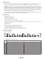
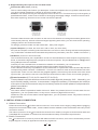
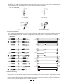
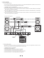
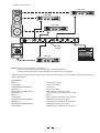
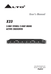
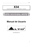
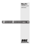
User's Manual
X34
3-WAY STEREO/ 4-WAY MONO
ACTIVE CROSSOVER
R
LTO
www.altoproaudio.com
Version 1.0 April 2002
English
SAFETY RELATED SYMBOLS
wire or disconnect the wiring of protective grounding
terminal.
CAUTION
Operating Conditions
This apparatus shall not be exposed to dripping or
splashing and that no objects filled with liquids,
such as vases, shall be placed on this apparatus.
To reduce the risk of fire or electric shock, do not
expose this apparatus to rain or moisture.
Do not use this apparatus near water.
Install in accordance with the manufacturer's
instructions. Do not install near any heat sources
such as radiators, heat registers, stoves, or other
apparatus (including amplifiers) that produce heat.
Do not block any ventilation openings.
No naked flame sources, such as lighted candles,
should be placed on the apparatus.
RISK OF ELECTRIC SHOCK
DO NOT OPEN
This symbol, wherever it appears, alerts you
to the presence of uninsulated dangerous voltage
inside the enclosure-voltage that may be sufficient to constitute a risk of shock.
This symbol ,wherever it appears ,alerts you
to important operating and maintenance
instructions in the accompanying literature .
Read the manual .
Protective grounding terminal .
Alternating current /voltage .
Hazardous live terminal .
ON: Denotes the apparatus turns on .
IMPORTANT SAFETY INSTRUCTIONS
OFF: Denotes the apparatus turns off ,because of
using the single pole switch ,be sure to unplug the
AC power to prevent any electric shock before you
proceed your service .
Read these instructions.
Follow all instructions.
Keep these instructions.
Heed all warnings.
Only use attachments/accessories specified by the
manufacturer.
WARNING: Describes precautions that should
be observed to prevent the danger of injury or
death to the user .
Power Cord and Plug
Do not defeat the safety purpose of the polarized
or grounding type plug. A polarized plug has two
blades with one wider than the other. A grounding
type plug has two blades and a third grounding
prong. The wide blade or the third prong are provided
for your safety. If the provided plug does not fit into
your outlet, consult an electrician for replacement
of the obsolete outlet.
Protect the power cord from being walked on or
pinched particularly at plugs, convenience receptacles ,
and the point where they exit from the apparatus.
CAUTION: Describes precautions that should
be observed to prevent danger of the apparatus .
WARNING
Power Supply
Ensure the source voltage matches the voltage of
the power supply before turning ON the apparatus.
Unplug this apparatus during lightning storms or when
unused for long periods of time .
External Connection
The external wiring connected to the output hazardous
live terminals requires installation by an instructed
person, or the use of ready-made leads or cords.
Cleaning
When the apparatus needs a cleaning, you can blow
off dust from the apparatus with a blower or clean
with rag etc. Don't use solvents such as benzol,
alcohol, or other fluids with very strong volatility and
flammability for cleaning the apparatus body.
Clean only with dry cloth.
Do not Remove any Cover
There are maybe some areas with high voltages
inside , to reduce the risk of electric shock, do not
remove any cover if the power supply is connected.
The cover should be removed by the qualified personnel
only.
No user serviceable parts inside.
Servicing
Refer all servicing to qualified personnel. To reduce
the risk of electric shock, do not perform any servicing
other than that contained in the operating instructions
unless you are qualified to do so .
Fuse
To prevent a fire, make sure to use fuses with specified
standard (current, voltage, type). Do not use a different
fuse or short circuit the fuse holder.
Before replacing the fuse, turn OFF the apparatus and
disconnected the power source.
Servicing is required when the apparatus has
been damaged in any way ,such as power supply
cord or plug is damaged , liquid has been spilled
or objects have fallen into the apparatus, the
apparatus has been exposed to rain or moisture,
does not operate normally, or has been dropped.
Protective Grounding
Make sure to connect the protective grounding to prevent
any electric shock before turning ON the apparatus.
Never cut off the internal or external protective grounding
1
Preface
Dear Customer:
Thanks for choosing
LTO Active Crossover and thanks for choosing the one of results of
AUDIO TEAM job and researches.
LTO
For our LTO AUDIO TEAM, music and sound are more than a job...are first of all passion and let us say...
our obsession!
We have been designing professional audio products for a long time in cooperation with some of the major
brands in the world in the audio field.
The LTO line presents unparalleled analogue and digital products made by Musicians for Musicians in
our R&D Centres in Italy, Netherlands, United Kingdom and Taiwan. The core of our digital audio products
is a sophisticated DSP (Digital sound processor) and a large range of state of the art algorithms which
have been developed by our Software Team for the last 7 years.
Because we are convinced you are the most important member of LTO AUDIO TEAM and the one confirming the quality of our job, we'd like to share with you our work and our dreams, pay attention to your
suggestions and your comments.
Following this idea we create our products and we will create the new ones! From our side, we guarantee
you and we will guarantee you also in future the best quality, the best fruits of our continuous researches
and the best prices.
Our LTO Active Crossover is the result of many hours of listening and tests involving common people,
area experts, musicians and technicians.
The results of this effort is an efficient and effective electronic crossover solution, which will give you precise
control and superior sound from your loudspeaker system.
Nothing else to add, but that we would like to thank all the people that made the LTO Active Crossover a
reality available to our customers, and thank our designers and all the LTO staff, there to make possible
the realization of products containing our idea of music and sound and there to support you, our customers,
in the best way, conscious that you are our best richness.
Thank you very much.
LTO AUDIO TEAM
2
TABLE OF CONTENTS
1. INTRODUCTION .......................................................................................... ........ .........4
2. FEATURE LIST .............................................................................................................4
3. CONTROL ELEMENTS ...................... ....................................................... .....................4
3.1 The Front Panel
a. Guidable Map for The Front Panel
b. Supplementary Descriptions for The Front Panel
3.2 The Rear Panel
a. Guidable Map for The Rear Panel
b. Supplementary Descriptions for The Rear Panel
4. INSTALLATION & CONNECTION ............................................................... ......... ...........6
4.1 Mains Connection
4.2 Audio Connection
4.3 Rack Mounting
5. APPLICATION ...................... ............................................................................ .............7
5.1 X34 3-Way Stereo
5.2 X34 4-Way Mono
6. TECHNICAL SPECIFICATIONS ...................... ...................................................... ...........9
7. WARRANTY ........... ...................... ........................................................... ......................9
3
1. INTRODUCTION
Thank you very much for expressing your confidence in LTO products by purchasing our X34 Active
Crossover. With the X34 you have acquired an extremely musical and flexible Active Crossover.
The LTO X34 Active Crossover is a single rack unit, dual channels electronic crossover capable of
managing the frequency control for stereo 3-way and mono 4-way speaker systems. The X34 Active
Crossover is an ideal crossover solution for most small and large PA systems, live sound venues, commercial
installations, recording studio monitors and DJ set-ups. In addition to its flexibility in configuring to
different sound systems, the X34 Active Crossover has advanced features such as Clip LED Indicators,
CD Horn Equalization, and individual Phase and Mute switches per frequency band.
The X34 Active Crossover is an effective and efficient electronic crossover solution, which will give you
precise control and superior sound from your loudspeaker system.
2. FEATURE LIST
Single rack unit ( 1U)
Robust and Compact design
Phase inversion switches
Servo-balanced XLR inputs/outputs.
State-variable Linkwitz / Riley 24dB/Octave filters
Switchable constant directivity horn equalization circuit for use with horns requiring a high frequency boost
Clip LED indicators
Mute switches
Designed for the most precise accurate control
Top audio performances with high slew rate circuity
Over than 115dB dynamic range for transparent sound
Manufactured Under ISO9001 Certified management system
3. CONTROL ELEMENTS
3.1 The Front Panel
CLIP
CLIP
LOW
MID
LOW
HIGH
MID
HIGH
CHANNEL 1
0
CHANNEL 2
350
200
0
1.6K
0
3K
0
0
0
200
1.6K
0
350
3K
X34
0
R
LTO
100
OFF
+6
INPUT LEVEL
(INPUT LEVEL)
2 3
+6
OFF
MUTE
LOW GAIN
4
5
700
90
1K
1K
+6
OFF
XOVER FREQ
MID GAIN
6
7
MUTE
800
10K
XOVER FREQ
(XOVER FREQ)
8
9
700
100
7K
OFF
+6
MUTE
+6
OFF
INPUT LEVEL
(INPUT LEVEL)
HIGH GAIN
(HIGH GAIN)
10 11
12 13
OFF
+6
MUTE
LOW GAIN
(SUB GAIN)
14 15
90
1K
XOVER FREQ
(XOVER FREQ)
16
1K
OFF
+6
MUTE
800
10K
XOVER FREQ
(XOVER FREQ)
MID GAIN
(LOW GAIN)
17
7K
18
19
ON
+6
OFF
OFF
MUTE
HIGH GAIN
(MID GAIN)
3W- STEREO
(4W- MONO) POWER
20 21
1
a. Guidable Map for The Front Panel
X34 3-way stereo / 4-way mono active crossover
3-WAY STEREO MODE
1
2
3
4
5
6
7
8
9
10
11
4-WAY MONO MODE
Power Switch
Ch1 MID Gain
Ch1 MID Mute
Ch1 MID-HIGH Crossover Frequency
Input Level
HIGH Clip LED
(not used)
(not used)
(not used)
(not used)
(not used)
MID-HIGH Crossover Frequency
Ch1 HIGH Gain
Ch1 HIGH Mute
HIGH Gain
HIGH Mute
Ch1 Input Level
Ch1 LOW,Ch1 MID&Ch1 HIGH Clip LEDs
Ch1 LOW Gain
Ch1 LOW Mute
Ch1 LOW-MID Crossover Frequency
4
3-WAY STEREO
4-WAY MONO
ACTIVE CROSSOVER
12
13
14
15
16
17
18
19
20
21
Ch2 Input Level
Ch2 LOW,Ch2 MID&Ch2 HIGH Clip LEDs
(not used)
SUB, LOW & MID Clip LEDs
Ch2 LOW Gain
Ch2 LOW Mute
Ch2 LOW-MID Crossover Frequency
SUB Gain
SUB Mute
SUB-LOW Crossover Frequency
Ch2 MID Gain
Ch2 MID Mute
Ch2 MID-HIGH Crossover Frequency
LOW Gain
LOW Mute
LOW-MID Crossover Frequency
Ch2 HIGH Gain
Ch2 HIGH Mute
MID Gain
MID Mute
b. Supplementary Descriptions for The Front Panel
Power switch(1)
Turn the apparatus ON/OFF.
Clip LED (3 for Ch1 and 13 for Ch2)
This LED will light when output capability is being exceeded with clipping distortion. Occasional flickering
of the Clip LED is acceptable, but if it remains on continuously, you should turn down the level control
or reduce the output level of the proceeding component to avoid audible distortion.
Mute switch (5,8,11 for Ch1 and 15,18,21 for Ch2)
These mute switches mute the input signal of each frequency range.
3.2 The Rear Panel
PUSH
110-120V
220-240V
STEREO
MONO
CD
BOOST
MODE
95-120V /210-240V 60-50Hz
Rated Power Consumption 10W
NEW
HIGH
PHASE
FUSE:
210-240V: T100mAL 250VAC
95-120V: 200mA 250VAC
REPLACE FUSE WITH CORRECT
TYPE ONLY
3WAY- STEREO
/ (4WAY- MONO)
22
23
PUSH
AC INPUT
HIGH OUT 2 / (MID OUT)
MID
PHASE
MID OUT 2 / (LOW OUT)
TIDE
NEW
LOW OUT 2 / (SUB OUT)
1
INPUT 2 / (NOT USED)
MID
PHASE
HIGH
PHASE
3
2
HIGH OUT 1 / (HIGH OUT)
MID OUT 1 (NOT USED)
CHANNEL 2
38
37
36
35
CD
BOOST
LOW OUT 1 / (NOT USED)
1
INPUT 1 / (INPUT)
CHANNEL 1
34
33 32
31
30
29
28
27
26
25
a. Guidable Map for The Rear Panel
X34 3-way stereo / 4-way mono active crossover
3-WAY STEREO MODE
22
23
24
25
26
27
28
29
30
31
32
33
34
35
36
37
38
TIDE
3
2
4-WAY MONO MODE
Fuse Holder
AC Inlet
Ch1 Line Input
Ch1 Constant Directivity Boost
Ch1 LOW Output
Ch1 MID Phase Inversion
Ch1 MID Output
Ch1 HIGH Phase Inversion
Ch1 HIGH Output
Ch2 Line Input
Stereo / Mono Mode
Ch2 Constant Directivity Boost
Ch2 LOW Output
Ch2 MID Phase Inversion
Ch2 MID Output
Ch2 HIGH Phase Inversion
Ch2 HIGH Output
5
Line Input
Constant Directivity Boost
(not used)
(not used)
(not used)
(not used)
HIGH Output
(not used)
(not used)
SUB Output
LOW Phase Inversion
LOW Output
MID Phase Inversion
MID Output
24
b. Supplementary Descriptions for The Rear Panel
Fuse holder & AC inlet ( 22 & 23 )
This is a dual voltage unit. Before you attempt to connect and operate the unit, please make sure that
your local voltage matches the voltage on the fuse-holder cover.
Caution: The fuse protecting the AC supplies circuits of this unit. The fuse can only be changed by a
qualified technician, in the event of a fault or changing the supply voltage. If the fuse continues to
blow after replacing, discontinue use of this unit before repaired.
220-240V
110-120V
220-240V
110-120V
THIS IS SET FOR
110V AC TO 120V
AC OPERATION
THIS IS SET FOR
220V AC TO 240V
AC OPERATION
The fuse-holder above the AC connector on the rear of the chassis has 3 triangular markers (please refer
to the above pictures), with two of these triangles opposing each other, your unit is set to the operating
Voltage printed next to these markers.
To change, pull fuse-holder out and rotate 180 ,then push in again.
Inputs & Outputs ( 24 & 26, 28, 30 for Ch1 and 31 & 34, 36, 38 for Ch2 )
All inputs and outputs are floating and balanced when connected to other floating and balanced equipment.
Any combination of balanced and unbalanced operation is permitted. ( see also " Audio Connection " )
CD Boost ( 25 for Ch1 and 33 for Ch2 )
The Constant Directivity horn equalization circuit is to be used with horns that require a high frequency
boost, to smooth the high frequency response of the sound system. The provided boost is [email protected]
rising 6dB per octave to 22.5kHz.
Consult your horn manufacturer to determine whether it is needed in your circumstance.
No changes need to be made to operate without the constant directivity boost.
If the constant directivity equalization circuit is desired on a particular channel then depress the
corresponding switch labeled " CD BOOST" . There is one switch for each channel located near to the
input socket. If two or more channels are ganged together, then use only the switch near to the used
input socket. ( the switch near to the unused input socket has no effect on the circuit when ganged ).
Phase inversion (27, 29, for Ch1 and 35,37 for Ch2)
These phase inversion switches reverse the audio signal's phase by 180 . Normally, you
won't need this switch, however, in some cases, it might be necessary. For example, the inversion
of the pins of the XLR connector may be necessary to alter the audio phase to compensate for
phase cancellation.
Mode switch (32)
This switch sets the operational mode of this unit. When it is pressed, this unit is in the state of mono
application, you can operate it as a 4-way mono crossover (high/mid/ low/ sub).
Otherwise, this unit is in the state of stereo application, you can operate it as a 3- way stereo crossover
(high/mid/low).
4. INSTALLATION & CONNECTION
4.1 Mains Connection
Please ensure that the LTO X34 Active Crossover is set to the correct supply voltage before plugging
the power cord into the wall outlet , use the same fuse as marked on the fuse holder at the AC power
connection socket.
The mains connection of the LTO X34 Active Crossover is made by using the enclosed mains cable and
a standard IEC receptacle. It meets all of the international safety certification requirements.
4.2 Audio Connection
The LTO X34 Active Crossover presents with balanced XLR connectors, and it can be interfaced by several
ways to support a variety of applications without any signal loss.
6
a. Wiring Configuration
Either the 1/4" TRS (Tip-Ring-Sleeve) jack or the XLR servo connector can be wired in balanced and
unbalanced modes. Please wire your systems as the following examples:
For 1/4" TRS jack
1/4"TRS jack
Unbalanced Input
1/4"TRS jack
Balanced Input
For XLR connector
XLR Unbalanced Input
XLR Balanced Input
b. In Line Connection
For these applications, the X34 Active Crossover provides XLR connectors to easily interface with most
professional audio devices. Follow the configuration examples below for your particular connection.
Balanced
TIP RING SLEEVE
Tip
Ring
Sleeve
SLEEVE RING TIP
TIP RING SLEEVE
Tip
Ring
Sleeve
1
2
3
1
2
3
Tip
Ring
Sleeve
1
2
3
Tip
Ring
Sleeve
1
2
3
Tip
1
2
3
Unbalanced
TIP RING SLEEVE
Sleeve
TIP SLEEVE
1
2
3
Tip
TIP SLEEVE
TIP RING SLEEVE
SLEEVE TIP
SLEEVE RING TIP
Centre
Screen
Tip
Sleeve
Sleeve
Tip
Ring
Sleeve
Tip
Ring
Sleeve
Tip
Centre
Screen
Sleeve
TIP SLEEVE
Tip
Ring
Sleeve
TIP RING SLEEVE
1
2
3
Centre
Screen
1
2
3
4.3. Rack Mounting
The most secure mounting is on a universal rack shelf available from various rack manufactures or your
music dealer. The X34 Active Crossover fits into one standard 19" rack unit of space. Please allow at least
an additional 4" depth for the connectors on the rear panel. Be sure that there is enough air space around
the unit for sufficient ventilation and please do not place the X34 Active Crossover on high temperature
devices such as power amplifiers etc. to avoid overheating.
7
5. APPLICATION
5.1 X34 3-Way Stereo
If you want to present your X34 Active Crossover in a 3-way stereo application, please connect the unit
in your system as the following illustration step by step:
1. Set Mode switch into stereo Mode.
2. Plug the Left line-in into INPUT 1 and the Right line-in into INPUT 2.
3.Connect the LOW OUT 1 to the Left input of the Low frequency amplifier, and the LOW OUT 2 to the Right
input of the Low frequency amplifier.
4.Connect the MID OUT 1 to the Left input of the Mid frequency amplifier, and the MID OUT 2 to the Right
input of the Mid frequency amplifier.
5.Connect the HIGH OUT 1 to the Left input of the High frequency amplifier, and the HIGH OUT 2 to the Right
input of the High frequency amplifier.
no patch cord required.
HIGH AMP
MID AMP
LOW AMP
PUSH
110-120V
220-240V
STEREO
MONO
CD
BOOST
MODE
PUSH
AC INPUT
95-120V /210-240V 60-50Hz
Rated Power Consumption 10W
NEW
HIGH
PHASE
FUSE:
210-240V: T100mAL 250VAC
95-120V: 200mA 250VAC
REPLACE FUSE WITH CORRECT
TYPE ONLY
3WAY- STEREO
HIGH OUT 2 / (MID OUT)
/ (4WAY- MONO)
MID
PHASE
MID OUT 2 / (LOW OUT)
LOW OUT 2 / (SUB OUT)
TIDE
NEW
1
INPUT 2 / (NOT USED)
MID
PHASE
HIGH
PHASE
3
2
HIGH OUT 1 / (HIGH OUT)
MID OUT 1 (NOT USED)
CHANNEL 2
CD
BOOST
LOW OUT 1 / (NOT USED)
TIDE
3
2
1
INPUT 1 / (INPUT)
CHANNEL 1
STEREO
MODE
MIXER
5.2 X34 4-Way Mono
Otherwise, if you want to present your X34 Active Crossover in a 4-way mono application, please connect
the unit to your system as the following illustration step by step:
1.Set Mode switch to mono Mode.
2.Plug the line-in into INPUT 1.
3.Connect LOW OUT 2 to the Sub frequency amplifier.
4.Connect MID OUT 2 to the Low frequency amplifier.
5.Connect HIGH OUT 2 to the Mid-range frequency amplifier.
6.Connect HIGH OUT 1 to the High frequency amplifier.
8
no patch cold required
HIGH AMP
MID AMP
LOW AMP
PUSH
110-120V
220-240V
STEREO
MONO
CD
BOOST
MODE
PUSH
AC INPUT
95-120V /210-240V 60-50Hz
Rated Power Consumption 10W
NEW
HIGH
PHASE
FUSE:
210-240V: T100mAL 250VAC
95-120V: 200mA 250VAC
REPLACE FUSE WITH CORRECT
TYPE ONLY
3WAY- STEREO
HIGH OUT 2 / (MID OUT)
/ (4WAY- MONO)
MID
PHASE
MID OUT 2 / (LOW OUT)
LOW OUT 2 / (SUB OUT)
TIDE
NEW
1
INPUT 2 / (NOT USED)
MID
PHASE
HIGH
PHASE
3
2
HIGH OUT 1 / (HIGH OUT)
MID OUT 1 (NOT USED)
CHANNEL 2
CD
BOOST
LOW OUT 1 / (NOT USED)
TIDE
3
2
1
INPUT 1 / (INPUT)
CHANNEL 1
MONO
MODE
SUB AMP
MIXER
NOTE: Do not connect anything to INPUT 2.
Do not connect anything from LOW OUT 1 and from MID OUT 1
(These inputs/outputs are automatically normalled when unplugged).
The same time, please pay more attention to the front panel control, for it is really different from the 3-way
stereo application .
Front Panel
INPUT 1
LOW Gain 1
LOW-MID XOVER FREQ 1
MID Gain 1
MID-HIGH XOVER FREQ 1
HIGH Gain 1
INPUT 2
LOW Gain 2
LOW-MID XOVER FREQ 2
MID Gain 2
MID-HIGH XOVER FREQ 2
HIGH Gain 2
main input control
set to 0 and Mute
(not used)
set to 0 and Mute
MID-HIGH Crossover control
High frequency amplifier level control
set to 0
Sub frequency amplifier level control
SUB-LOW Crossover control
Low frequency amplifier level control
LOW-MID Crossover control
Mid frequency amplifier level control
9
6. TECHNICAL SPECIFICATIONS
Electrical
LOW-MID Frequency Range
MID-HIGH Frequency Range
HUM & Noise
LOW Section (Output@0dB)
MID S ection (O utput @0dB)
HIGH Section(Output @0dB)
S/N Ratio
90Hz-1KHz
800Hz-10KHz
Av=0db, fc=230Hz,2.3KHz
98dBu
-95dBu
93dBu
114dB
Controls
Input Level
Output Level
CD Boost
Mute
Phase
Power Supply
Connector type
Type
Mains supply
Power Rating
continuously variable
low, high continuously variable
rear panel switch
low, mid, high front panel switches
rear panel switch
3-pole IEC , grounded
Servo controlled , stabilized
95-120V /210-240V ,60-50Hz
10W
Physical
Dimensions
Weight
483(W) 194.5(D)
2.5Kg(5.51lb)
10
44(H)mm (19"
7.7"
1.7")
7. WARRANTY
1. WARRANTY REGISTRATION CARD
To obtain Warranty Service, the buyer should first fill out and return the enclosed Warranty Registration
Card within 10 days of the Purchase Date.
All the information presented in this Warranty Registration Card gives the manufacturer a better understanding of the sales status, so as to purport a more effective and efficient after-sales warranty service.
Please fill out all the information carefully and genuinely, miswriting or absence of this card will void your
warranty service.
2. RETURN NOTICE
2.1 In case of return for any warranty service, please make sure that the product is well packed in its original
shipping carton, and it can protect your unit from any other extra damage.
2.2 Please provide a copy of your sales receipt or other proof of purchase with the returned machine ,and
give detail information about your return address and contact telephone number .
2.3 A brief description of the defect will be appreciated.
2.4 Please prepay all the costs involved in the return shipping, handling and insurance.
3. TERMS AND CONDITIONS
3.1
LTO warrants that this product will be free from any defects in materials and/or workmanship for
a period of 1 year from the purchase date if you have completed the Warranty Registration Card in
time.
3.2 The warranty service is only available to the original consumer, who purchased this product directly
from the retail dealer, and it can not be transferred.
3.3 During the warranty service, LTO may repair or replace this product at its own option at no charge to
you for parts or for labor in accordance with the right side of this limited warranty.
3.4 This warranty does not apply to the damages to this product that occurred as the following conditions:
Instead of operating in accordance with the user's manual thoroughly, any abuse or misuse of this
product.
Normal tear and wear.
The product has been altered or modified in any way.
Damage which may have been caused either directly or indirectly by another product / force / etc
Abnormal service or repairing by anyone other than the qualified personnel or technician.
And in such cases, all the expenses will be charged to the buyer.
3.5 In no event shall LTO be liable for any incidental or consequential damages. Some states do not allow
the exclusion or limitation of incidental or consequential damages, so the above exclusion or limitation
may not apply to you.
3.6 This warranty gives you the specific rights, and these rights are compatible with the state laws, you
may also have other statutory rights that may vary from state to state.
11