1
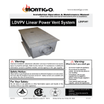
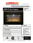
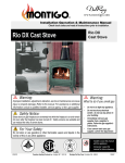
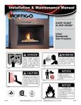
Installation & Maintenance Manual LDVPV47 LDVPV Linear Power Vent System DANGER Read and understand this manual. Improper installation, adjustment, alteration, service or maintenance can cause serious injury, property damage or even death. For assistance or additional information consult a qualified installer, service agency or the gas supplier. CAUTION Glass doors on gas fireplaces are extremely hot while the fireplace is on and remain hot even after the fireplace has been turned off. Safety screens are available and can reduce the risks of severe burns. Please keep children away from the fireplace at all times. WARNING Do not store or use gasoline or any other flammable vapors and liquids in the vicinity of this or any other gas burning appliance. A fire or explosion my occur causing serious injury, property damage or even death. NOTICE Installer: Leave this manual with the appliance. Do not remove. Consumer: Retain this manual for maintenance and future reference. Do not Discard. DANGER Blank IF YOU SMELL GAS Do not try to light any appliance. Do not touch any electrical switch; do not use any phone in your building. Immediately call your gas supplier from a neighbor's phone. Follow the gas supplier's instructions. If you cannot reach your gas supplier, call the fire department. Blank Flammable materials Toxic Corrosive Danger overhead crane Blank Flammable materials Explosion risk Toxic Corrosive Danger overhead crane Fork lift trucks High voltage General Warning Laser Radiation Explosion risk Biohazard Oxidising Hot surface Danger of entrapment Fork lift trucks Danger of death High voltage Flammable materials Explosion risk Toxic Corrosive Danger overhead crane Fork lift trucks High voltage General Warning Laser Radiation Biohazard Oxidising Hot surface Danger of entrapment Danger of death Slippery floor Watch your step High temperatures Glass hazard Danger of suffocation Hot surface Irritant Cutting Blank ® C XG0750 US General Warning Laser Radiation Biohazard Danger of entrapment Danger of death Irritant Slippery floor Watch your step Cutting High temperatures Glass hazard Danger of suffocation Gas bottles Watch for falling objects Explosion risk Electricity Danger for cutter Entrapment hazard Battery hazard Rotating parts Corrosive Danger overhead crane Flammable materials Toxic Oxidising Fork lift trucks High voltage Glass hazard Danger of suffocation Irritant Slippery floor Watch your step Cutting High temperatures Gas bottles Watch for falling objectsfield Strong magnetic Electricity Danger for cutter Entrapment hazard Battery hazard Rotating parts Low temperature Optical radiation Laser Radiation Biohazard Non ionizing radiation Oxidising Radiation General Warning Hot surface Hazardous to the Environment Danger of entrapment Danger of harming your hands Danger of death Gas bottles Watch for falling objects Strong magnetic field Electricity Danger for cutter Optical radiation Entrapment hazard Battery hazard Non ionizing radiation Radiation Hazardous to the Environment Danger of harming your hands Irritant Slippery floor Watch your step Cutting High temperatures Glass hazard Danger of suffocation Low temperature Strong magnetic field Optical radiation Non ionizing radiation Radiation Hazardous to the Environment Danger of harming your hands Gas bottles Watch for falling objects Electricity Danger for cutter Entrapment hazard Battery hazard Rotating parts Low temperature Rotating parts Canadian Heating Products Inc. Langley, BC V4W 4A1 | Montigo Del Ray Corp. Ferndale, WA 98248 112911 LDVPV47 Linear Power Vent System Safety Alert Key DANGER Indicates a hazardous situation which, if not avoided, WILL result in death or serious injury or property damage. CAUTION Indicates a hazardous situation which, if not avoided, WILL result in minor or moderate injury. WARNING Indicates a hazardous situation which, if not avoided, COULD result in death or serious injury or property damage. NOTICE Address practices that are important, but not related to personal injury Table of Contents Safety Alert Key ..................................................................................2 Introduction ..................................................................................3 Before you Start ..................................................................................3 Section 1: Installation ........................................................................4 - 9 Unit Dimensions ..................................................................................4 Installation of Pipe Diluter.........................................................................5 Installation of Pipe Reducer & Diluter.......................................................5 Flush Vent Option ..................................................................................6 Installation for Horizontal Venting.............................................................7 Installation for Horizontal Downward Vent...............................................8 Installing the Vertical Linear Power Vent..................................................8 Installing the Horizontal Linear Power Vent..............................................8 Mounting of Linear Power Vent...............................................................9 Wiring Installation ..................................................................................9 Wiring Schematic ................................................................................10 Parts List ................................................................................ 11 Appendix A. Termination Locations................................................................12 B. Warranty ................................................................................13 C. State of Massachusetts.............................................................14 Page 2 XG00750 - 112911 LDVPV47 Linear Power Vent System NOTICE You must read and understand this manual prior to installation, operation or troubleshooting this appliance. Please retain this owner’s manual for furure reference and maintenance. Introduction Selecting and Installing the Fireplace The Linear Power Vent System must only be used with a Montigo Direct Vent Fireplace. When selecting a gas fireplace for use with the Linear Power Vent System, take into consideration the various requirements and limitations in the venting installation section of the Model's manual: Models Must Be Equipped with Electronic Ignition (HSI/IPI) Only models equipped with an electronic ignition system may be installed with the Linear Power Vent System. This system allows for greater flexibility on venting requirements. For example downward vertical vent runs are possible with an HSI/IPI system, as outlined in the Venting Section. All fireplaces with 5"/8" venting must be reduced to 4"/7" venting in order to be used with the Linear Power Vent System. General Information This installation guide covers installation of the Linear Power Vent System only. This system is designed to allow installation of gas fireplaces that cannot be done with a standard Direct Vent gas fireplace installation. Specifications and instructions pertaining to your chosen fireplace must be followed. Please read this Installation Operation and Maintenance Instructions carefully before operating this equipment. Standard Series (4"/7" dia.) Termination System: LDVPV47 - Linear Power Vent System Pre/Post Purge Control Box RHSIT05 -Control module, provides pre/post purge. (HSI System) ECB-007 Post Purge control box (IPI System) Power Cord Harnesses: LPVH10 -10 foot power cord and harness LPVH20 -20 foot power cord and harness LPVH30 -30 foot power cord and harness LPVH40 -40 foot power cord and harness LPVH50 -50 foot power cord and harness LPVH60 -60 foot power cord and harness LPVH70 -70 foot power cord and harness LPVH80 -80 foot power cord and harness CAUTION Ensure perforated air holes in the new pipe adapter / restrictor are not covered when installing new pipe connection. XG0750 - 112911 Before You Begin Minimum clearances of 1" from vent to all combustible materials must be maintained. The LDVPV must only be installed with Montigo venting components. The LDVPV may be used with any of the available Montigo terminations. In order to maintain the power vent system integrity all 4" and 7" venting connections must be fastened with three self tapping screws. Installation of the LDVPV must comply with this manual, and be completed by a qualified professional. Plan the layout of the installation's venting run before starting the installation. The MAXIMUM total allowable length; Refer to Linear Power Vent Installation Section, Page 4-6. Downward venting is allowable. Please refer to Page 5 for a table and illustrations regarding the limitations of this type of installation. Minimum length of straight pipe between the Fireplace and the Power Vent is: 2 feet Access / Service Panel, must maintain 1" clearance. Minimum 30% free air must be supplied to the motor. Disconnect the power supply when installing and/or servicing the fireplace or the power vent system. CAUTIO N When cold air enters warm building interiors, primarily at the air intake end, condensation may occur on the exterior of the flex pipe. To limit condensation, install insulation over the last 20 feet of flex pipe. Sloping the last 20 - 0 feet of flex pipe downward to the exterior of the building may also aid in eliminating condensation. Ensure the termination is securly fastened and is sealed to the flex pipe. Fasten the termination to building exterior with water tight sealant and appropriate fasteners. CAUTION Due to high operating temperatures, this appliance should be located out of traffic & away from furniture and draperies. Children and adults should be alerted to the hazards of the high surface temperature, which could cause burns or clothing ignition. Young children should be carefully supervised when they are in the same room as the appliance. Clothing or other flammable materials should not be placed on or near the appliance. Page 3 LDVPV47 Linear Power Vent System Installation 2 7/16" 10 1/16" 1 5/16" 1.0 FAN SHIELD 27 15/16" 33 3/4" 26 16 5/16" 14 7/16" 4 16 7/16" 7 1.0 Figure 1. LDVPV47 Linear Power Vent dimensions. Page 4 XG0750 - 112911 LDVPV47 Linear Power Vent System Installation Section: CAUTION Ensure perforated air holes in the new pipe adapter / diluter are not covered when installing the new pipe connection. Installation of Pipe Diluter The Installation of the LDV Air Circulator Pipe Reducer on your fireplace: Model No's. that use 4" /7" Vent 1. Install the Pipe Diluter as shown below. Fllue Diluter Collar Installation of Pipe Reducer & Diluter The Installation of the LDV Air Circulator Pipe Reducer on your fireplace: Model No's. that use 5" /8" Vent 1. Install the Pipe Reducer & Diluter as shown below. 8" to 7" Reducer Flue Reducer / Diluter Slide Reducer over 4" Flue Adapter Slide Reducer/ Diluter over 4" Flue Adapter Top of Fireplace Top of Fireplace Existing 4" Flue Adapter Existing 4" Flue Adapter Figure 2a. Installation of 4" / 7" Flue Reducer. Figure 2b. Installation of 5"/8" Flue Reducer. See page 11 for detailed part numbers. See page 11 for detailed part numbers. Venting Installation The Internal Power Vent must be installed with a gas fireplace equipped with an electronic ignition system. When installing the venting, the installation must adhere to the Venting Installation Section in the fireplace's Installation Operation and Maintenance Instructions, as well as the following guidelines: Ensure that the planned termination location is acceptable as shown in Appendix A. Minimum of 2 feet of straight pipe before the power vent. XG0750 -112911 Page 5 LDVPV47 Linear Power Vent System Installation LDVP47 Power Vent Intake Termination Exhaust M Wall Switch Exterior Wall Adapter, See Appendix II Remote wiring to Power Vent from Post Purge Control Fireplace Post Purge Hot Service Igniter Electronic Ignition Gas Control 110VAC Not Switched Figure 2. Schematic for the Linear Power Venter Non-combustble Overhang LDVPV47, 110V power supply, 2Amp MAX. Power Cord 10’ Long, Part No.__EPVH-1 20’ Long, Part No.__EPVH-2 30’ Long, Part No.__EPVH-3 40’ Long, Part No.__EPVH-4 50’ Long, Part No.__EPVH-5 60’ Long, Part No.__EPVH-6 70’ Long, Part No.__EPVH-7 80’ Long, Part No.__EPVH-8 90’ Long, Part No.__EPVH-9 100’ Long, Part No._EPVH-100 Hot Service Igniter Electronic Ignition Gas Control 110V power supply, 4Amp MAX. Exterior Wall Optional Stainless Steel louvered Termination kit. Wall Switch Transformer for HSI, 2Amp MAX. Part No. __ECB006__ Figure 3. Flush vent Option for the Linear Power Venter Page 6 XG0750 - 112911 LDVPV47 Linear Power Vent System Installation Section: WARNING Montigo is not responsible for any water damage that may occur from installing equipment other than what is specified in this document. Linear Power Vent - Horizontal Vent Multi-elbow installations are possible up to a maximum one-hundred feet (100'-0"), with three (3) 90° elbows. Minimum vent run from Fireplace to Power Vent must be two feet, (2'-0"). Maximum allowable vent run must be reduced by Ten feet (10'-0") for every 90° elbow added. With a snorkel Termination, reduce the total vent run by an additional twenty feet (20'-0"). Figure's 3a and 3b. Linear Power Vent - Vertical Vent Multi-elbow installations are possible up to a maximum one-hundred thirty feet (130'-0"), with three (3) 90° elbows. Minimum vent run from Fireplace to Power Vent must be two feet, (2'-0"). Maximum allowable vent run must be reduced by Ten feet (10'-0") for every 90° elbow added. Figure's 4a and 4b. Example A. Vertical Mounting with Vertical Vent Run Termination 2’-0 ” MIN Vertical Flex Pipe Example A. Vertical Mounting with horizontal Vent Run 90deg Elbow Termination 90deg Elbow Horizontal Run Flex Pipe 90deg Elbow Vertical Flex Pipe Vertical Installed Linear Power Vent Snorkel Termination Vertical Installed Linear Power Vent 2’-0 ” MIN 2’-0 ” MIN 90deg Elbow 90deg Elbow 90deg Elbow Important: 90deg Elbow Maximum Vent Run not to exceed One-Hundred Thirty (130’-0”) feet. Important: Maximum Vent Run not to exceed One-Hundred feet (100’-0”) feet. Figure 4a. Vertical Vent for the Linear Power Venter Figure 3a. Vertical Mounting for the Linear Power Venter Example B. Vertical Mounting with Vertical Vent Run Example B. Horizontal Mounting with horizontal Vent Run 90deg Elbow Horizontal Installed Linear Power Vent Termination 2’-0 ” MIN Horizontal Run Flex Pipe Termination 90deg Elbow 90deg Elbow Available Option Vertical Flex Pipe Vertical Installed Linear Power Vent Snorkel Termination 90deg Elbow 90deg Elbow 90deg Elbow 90deg Elbow Important: Maximum Vent Run not to exceed One-Hundred feet (100’-0”) feet. Figure 3b. Horizontal Vent for the Linear Power Vent Termination Snorkel Vertical Flex Pipe Important: Maximum Vent Run not to exceed One-Hundred Thirty (130’-0”) feet. Figure 4b. VerticaI Linear Power Vent with Vertical Vent Run. XG0750 -112911 Page 7 LDVPV47 Linear Power Vent System Installation Linear Power Vent - Horizontal / Downward Vent Multi-elbow installations are possible up to a maximum eighty feet (80'-0"), with three (3) 90° elbows. Minimum vent run from Fireplace to Power Vent must be two feet, (2'-0"). Maximum allowable vent run must be reduced by Ten feet (10'-0") for every Additional elbow added. Deduct ten feet (10'-0") of vent length for every Additional one foot (1'-0") of vent run traveling in a downward direction. Horizontal Installed Linear Power Vent 90deg Elbow 90deg Elbow Vertical Flex Pipe Optional location of Horizontal mounted Linear Power Vent Horizontal Run Flex Pipe Installing the Horizontal Linear Power Vent 1. The linear power vent can be installed to existing stud construction or directly to cement wall or roof. The LDVPV must maintain the clearance to combustibles shown in Figure, 4a. The required service access panel must be framed at 18" X 18". To enclose the service access panel, (at less than 1") a minimum 30% free air must be supplied at all times. 2. Plug the power chord into the available slot in the linear power vent. 3. Secure all venting joints with at least three self-tapping screws. Combustible Materials 3” Clearance 6’-0” Termination Important: Maximum Vent Run not to exceed Eighty feet (80’-0”) feet. 3” Clearance Figure 5a. HorizontaI Linear Power Vent with Horizontal Vent Run. (Optional installation location shown). Selecting A Termination Location Combustible Materials Top View Combustible Materials 1” Clearance Please consult Appendix I, to ensure that the location of the vent run termination is within the guidelines. Installing the Vertical Linear Power Vent 1. The linear power vent can be installed to existing stud construction or directly to cement wall or roof. The LDVPV must maintain 1" clearances to combustibles. The required service access panel must be framed at 18" X 18". To enclose the service access panel, (at less than 1") a minimum 30% free air must be supplied at all times. 2. Plug the power chord into the available slot in the linear power vent. 3. Secure all venting joints with at least three self-tapping screws. 2” Clearance 10” Clearance 10” Clearance Combustible Drywall ceiling, with access panel Side View Figure 6a. LDVPV47 Linear Power Vent, Horizontal framing dimensions. 18 18 Note: The required service access panel must be framed at 18" X 18". To enclose the service access panel , (at less than 1") a minimum 30% free air must be supplied at all times. Figure 6. LDVPV47 Linear Power Vent, Vertical framing dimensions. Page 8 XG0750 - 112911 LDVPV47 Linear Power Vent System Installation Section: Mounting of Linear Power Vent for specific Model Fireplaces L52-DF, and L52-DF-ST Gas fireplace models. 4 -0 Clearance / void must be maintained at both ends of Power vent unit, thru to exterior termination. This clearance does not include wire conduit, pipe or other neccessary building component. It does however include fibre insulation, and/or other heat retaining materials. 4’-0” MIN 4’-0” MIN Power Vent 1” MIN Figure 7. LDVPV47 Linear Power Vent Framing in steel studs. Figure 8. L52-DF and L52-DF-ST vent clearances. Wiring Installation Connect the wiring to the linear power vent as outlined in the previous section, and connect the wiring to the fireplace as outlined in the schematic below. Ensure that the proper clearances are maintained for the wiring and conduit. Important: 0” Clearance is required on mounting surface if LDVPV is Listed under 28,000Btu. If over 28,000Btu 1” must be maintained or 30% free air space surounding LDVPV. When installing the wiring it must never run above the vent run and it must be at least 1" clear of all venting. Figure 7a. LDVPV47 Linear Power Vent Framing to cement roof. 1” Clearance Figure 9. Conduit and Wiring Clearances. XG0750 -112911 Page 9 LDVPV47 Linear Power Vent System Installation Wiring Installation Main Junction Box BX Conduit Receptical Upper Casing of Fireplace To 115V AC Supply W Bk Motor W L2 Bk L1 W 115V G R Transformer R 24V Limit Switch Air Proving Switch Strain Relief TDR W TDR Coil Bk Fuse Bl Wall Switch Bk Bl W Strain Relief Legend Denotes Line Voltage Denotes Low Voltage Denotes Wire Connector Bk R Gas Control Connector Figure 10. Wiring schematic for the Post Purge Control Module. Page 10 XG0750 - 112911 LDVPV47 Linear Power Vent System Replacement Parts Description Order Code LPVC56 (Installed with LDVPV47 on the Following models) LVA52ST 4" L52DF-ST ONLY 5" Dilution holes: 2@ 1.250" Exhaust hole: Ø 3" 7" / 8" Adapter collar Included in kit LPVC55 (Installed with LDVPV47 on the Following models) L52DFN ONLY LVA522H 4" 5" Dilution holes: 2@ 1.250" Exhaust hole: Ø 2.375" 7" / 8" Adapter collar Included in kit LPVC54 (Installed with LDVPV47 on the Following models) M40-Series L38DFN, L42DFN H38DFN, HL38DFN H42DFN, HL42DFN L38DF-ST, L42DF-ST H38DF-ST, HL38DF-ST H42DF-ST, HL42DF-ST LVA5487 4" Dilution holes: 2@ 1.250" Exhaust hole: Ø 2.375" 7" / 8" Adapter collar Included in kit 5" H52CA03 (Installed with LDVPV58 on the Following models) H34DFN, HL34DFN, H34DFL HR34DFN XG0181 - 112811 LVA47 4" 4" Dilution holes: 4@ 1.250" Exhaust hole: Ø 2.375" Page 11 LDVPV47 Linear Power Vent System Appendix Appendix A: Termination Locations A = clearance to the termination frame above grade, veranda, porch, deck, or balcony [16 inches (41 cm) minimum] B = clearance to door, or sides and top of window, that may be opened [16 inches (41 cm) minimum for appliances ≤100 000 BTU/H (30kW)] C = clearance to bottom of window that may be opened horizontally [36 inches (92 cm) minimum for appliances ≤100 000 BTU/H (30kW)] D = no clearance to permanently closed window when installed with approved glass penetration termination E = clearance to permanently closed window [16 inches 41 cm recommended to prevent condensation on window] F = vertical clearance to ventilated soffit located above the termination within a horizontal distance of 2 feet (61 cm) from the centreline of the termination [22 inches (56 cm) minimum] G = clearance to unventilated soffit [16 inches (41 cm) minimum to noncombustibles] [22 inches (56 cm) minimum to combustibles] H = clearance to outside corner [9 inches (23 cm) minimum] I = clearance to inside corner [12 inches (31 cm) minimum] J = * not to be installed above a meter/regulator assembly within 40" (103 cm) horizontally from the centreline of the regulator K = clearance to service regulator vent outlet [3 feet minimum in the United States] [*6 feet (1.8 m) minimum in Canada] L = clearance to non-mechanical air supply inlet to building or the combustion air inlet to any other appliance [16 inches (41 cm) minimum for appliances ≤100 000 BTU/H (30kW)] M = clearance to mechanical air supply inlet [*6 feet (1.8 m) minimum] N = † clearance above paved sidewalk or a paved driveway located on public property [*7 feet (2.1 m) minimum] P = clearance under veranda, porch, deck, or balcony [16 inches (41 cm) minimum‡ to non-combustibles] [22 inches (56 cm) minimum‡ to combustibles] Q = clearance above a roof [24 inches (61 cm) minimum] R = clearance to adjacent walls and neighboring buildings [18 inches (46 cm) Page 12 minimum] S = clearance from corner in recessed location [12 inches (31 cm) minimum] T = maximum depth in recessed location [48 inches (122 cm) minimum] U = minimum width for back wall of recessed location [24 inches (61 cm) minimum] V = no horizontal clearance between the frames of two terminations that are level. W = horizontal clearance between the frames of two terminations that are not level. [36 inches (92 cm) minimum] † a vent shall not terminate directly above a sidewalk or paved driveway which is located between two single family dwellings and serves both dwellings ‡ only permitted if veranda, porch, deck, or balcony has an open side that is equal to or greater than the depth of the enclosed area * as specified in CGA B149 Installation Codes. Note: local Codes or Regulations may require different clearance. XG0181 - 112811 LDVPV47 Linear Power Vent System Appendix Appendix B: Warranty The Warranty The Companies warrants the Montigo Gas Appliance to be free from defects in materials and workmanship at the time of manufacture. On the Montigo fireplace, there is a ten-year warranty on the firebox and its components, a five-year warranty on the main burner and pilot burner, and a one-year warranty on the gas control valve, fibre logs and Power Vent Module. The Glass, plated / painted finishes, and refractory lining are exempt from the warranty. Remedy And Exclusions The coverage of this Warranty is limited to all components of the Gas Appliance manufactured by The Companies. This Warranty only covers Montigo Gas Appliances installed in the United States or Canada. If the components of the Gas Appliance covered by this Warranty are found to be defective within the time frame stated (see The Companies right of investigation outlined below). The Companies will, at its option, replace or repair defective components of the Gas Appliance manufactured by The Companies at no charge, and will also pay for reasonable labour costs incurred in replacing or repairing components. If repair or replacement is not commercially practical, The Companies will, at its option, refund the purchase price of the Montigo Gas Appliance. This Warranty covers only parts and labour as provided above. In no case shall The Companies be responsible for materials, components, or construction which are not manufactured or supplied by The Companies, or for the labour necessary to install, repair or remove such materials, components or construction. All replacement or repair components will be shipped F.O.B. the nearest The Companies factory. Qualifications To The Warranty The Gas Appliance Warranty outlined above is further subject to the following qualifications: (1) The Gas Appliance must be installed in accordance with The Companies installation instructions and local building codes. The Warranty on this Montigo Gas Appliance covers only the component parts manufactured by The Companies. The use of components manufactured by others with this Montigo Gas Appliance could create serious safety hazards, may result in the denial of certification by recognized national safety agencies, and could be in violation of local building codes. This warranty does not cover any damages occurring from the use of any components not manufactured or supplied by The Companies (2) The Montigo Gas Appliance must be subjected to normal use. The Gas Appliances are designed to burn gas only. Burning conventional fireplace fuels such as wood, coal or any other solid fuel will cause damage to the Gas Appliance, will produce excessive temperatures and will result in a fire hazard. Limitations On Liability It is expressly agreed and understood that The Companies sole obligation, and purchaser's exclusive remedy under this Warranty, under any other warranty, expressed or implied, or in contract, tort or otherwise, shall be limited to replacement, repair, or refund, as specified above. In no event shall The Companies be responsible for any incidental or consequential damages caused by defects in its products, whether such damage occurs or is discovered before or after replacement or repair, and whether or not such damage is caused by The Companies negligence. Some states do not allow the exclusion or limitation of incidental or consequential damages, so the above limitation or exclusion may not apply to you. The duration of any implied warranty with respect to this Montigo Gas Appliance is limited to the duration of the foregoing warranty. Some states do not allow limitation on how long an implied warranty lasts, so the above may not apply to you. Investigation Of Claims Against Warranty The Companies reserves the right to investigate any and all claims against this Warranty and to decide upon method of settlement. The Companies Are Not Responsible For Work Done Without Written Consent The Companies shall in no event be responsible for any warranty work done without first obtaining The Companies written consent. Dealers Have No Authority To Alter This Warranty The Companies employees and dealers have no authority to make any warranties nor to authorize any remedies in addition to or inconsistent with those stated above. How To Register A Claim Against Warranty In order for any claim under this Warranty to be valid, The Companies must be notified of the claimed defect in writing or by telephone, as soon as reasonably possible after the defect is discovered. Claims against this Warranty in writing should include the date of installation, and a description of the defect. Other Rights This Warranty gives you specific legal rights, and you may also have other rights which vary from state to state. NOTE: The Companies as stated above refer to - Canadian Heating Products Inc. and/or Montigo Del Ray Corp. Canadian Heating Products Inc. and/or Montigo DelRay Corp. reserves the right to make changes at any time, without notice, in design, materials, specifications, prices and also to discontinue colors, styles and products. XG0181 - 112811 Page 13 LDVPV47 Linear Power Vent System Appendix Appendix C: State of Massachusetts Amendment (Gas Fireplace / Equipment sold in the State of Massachusetts) 5.08: Modifications to NFPA-54, Chapter 10 (1) Revise NFPA-54 section 10.5.4.2 by adding a second exception as follows: Existing chimneys shall be permitted to have their use continued when a gas conversion burner is installed, and shall be equipped with a manually reset device that will automatically shut off the gas to the burner in the event of a sustained back-draft. (2) Revise 10.8.3 by adding the following additional requirements: (a) For all side wall horizontally vented gas fueled equipment installed in every dwelling, building or structure used in whole or in part for residential purposes, including those owned or operated by the Commonwealth and where the side wall exhaust vent termination is less than seven (7) feet above finished grade in the area of the venting, including but not limited to decks and porches, the following requirements shall be satisfied: 1. INSTALLATION OF CARBON MONOXIDE DETECTORS. At the time of installation of the side wall horizontal vented gas fueled equipment, the installing plumber or gas fitter shall observe that a hard wired carbon monoxide detector with an alarm and battery back-up is installed on the floor level where the gas equipment is to be installed. In addition, the installing plumber or gas fitter shall observe that a battery operated or hard wired carbon monoxide detector with an alarm is installed on each additional level of the dwelling, building or structure served by the side wall horizontal vented gas fueled equipment. It shall be the responsibility of the property owner to secure the services of qualified licensed professionals for the installation of hard wired carbon monoxide detectors a. In the event that the side wall horizontally vented gas fueled equipment is installed in a crawl space or an attic, the hard wired carbon monoxide detector with alarm and battery back-up may be installed on the next adjacent floor level. b. In the event that the requirements of this subdivision can not be met at the time of completion of installation, the owner shall have a period of thirty (30) days to comply with the above requirements; provided, however, that during said thirty (30) day period, a battery operated carbon monoxide detector with an alarm shall be installed. 2. APPROVED CARBON MONOXIDE DETECTORS. Each carbon monoxide detector as required in accordance with the above provisions shall comply with NFPA 720 and be ANSI/UL 2042 listed and IAS certified. 3. SIGNAGE. A metal or plastic identification plate shall be permanently mounted to the exterior of the building at a minimum height of eight (8) feet above grade directly in line with the exhaust vent terminal for the horizontally vented gas fueled heating appliance or equipment. The sign shall read, in print size no less than one-half (1/2) inch in size, “GAS VENT DIRECTLY BELOW. KEEP CLEAR OF ALL OBSTRUCTIONS”. 4. INSPECTION. The state or local gas inspector of the side wall horizontally vented gas fueled equipment shall not approve the installation unless, upon inspection, the inspector observes carbon monoxide detectors and signage installed in accordance with the provisions of 248 CMR 5.08(2)(a)1 through 4. (b) EXEMPTIONS: The following equipment is exempt from 248 CMR 5.08(2)(a)1 through 4: 1. The equipment listed in Chapter 10 entitled “Equipment Not Required To Be Vented” in the most current edition of NFPA 54 as adopted by the Board; and 2. Product Approved side wall horizontally vented gas fueled equipment installed in a room or structure separate from the dwelling, building or structure used in whole or in part for residential purposes. (c) MANUFACTURER REQUIREMENTS - GAS EQUIPMENT VENTING SYSTEM PROVIDED. When the manufacturer of Product Approved side wall horizontally vented gas equipment provides a venting system design or venting system components with the equipment, the instructions provided by the manufacturer for installation of the equipment and the venting system shall include: 1. Detailed instructions for the installation of the venting system design or the venting system components; and 2. A complete parts list for the venting system design or venting system. (d) MANUFACTURER REQUIREMENTS - GAS EQUIPMENT VENTING SYSTEM NOT PROVIDED. When the manufacturer of a Product Approved side wall horizontally vented gas fueled equipment does not provide the parts for venting the flue gases, but identifies “special venting systems”, the following requirements shall be satisfied by the manufacturer: 1. The referenced “special venting system” instructions shall be included with the appliance or equipment installation instructions; and 2. The “special venting systems” shall be Product Approved by the Board, and the instructions for that system shall include a parts list and detailed installation instructions. (e) A copy of all installation instructions for all Product Approved side wall horizontally vented gas fueled equipment, all venting instructions, all parts lists for venting instructions, and/or all venting design instructions shall remain with the appliance or equipment at the completion of the installation. (3) After NFPA-54 section 10.10.4.2 add a new section 10.10.4.3 as follows: When more than four gas appliances are to be vented through a common gas vent or common horizontal vent manifold, a plan of the proposed vent installation shall be submitted to the Inspector and the serving gas supplier for review and approval. Extraction from: Massachusetts Rules and Regulations 5.00: Amendments To 2002 Edition Of ANSI Z223.1-NFPA-54 Page 14 XG0181 - 112811 L42DF* Indoor Gas Fireplace Notes XG0181 - 053111 Notes Page 15 LDVPV47 Linear Power Vent System Ferndale, Washington TF: 1.800.789.6236 FX: 1.866.3000.0927 XG0750 - 112911 Langley, British Columbia TF: 1.800.378.3115 FX: 1.604.607.6462