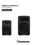
1
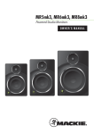
SRM550 and SRM650 1600W 2-WAY POWERED LOUDSPEAKERS OWNER’S MANUAL SRM550/SRM650 Powered Loudspeakers Important Safety Instructions 1. Read these instructions. 2. Keep these instructions. 3. Heed all warnings. 4. Follow all instructions. 5. Do not use this apparatus near water. 6. Clean only with a dry cloth. 7. Do not block any ventilation openings. Install in accordance with the manufacturer’s instructions. 8. Do not install near any heat sources such as radiators, heat registers, stoves, or other apparatus (including amplifiers) that produce heat. 9. Do not defeat the safety purpose of the polarized or grounding-type plug. A polarized plug has two blades with one wider than the other. A groundingtype plug has two blades and a third grounding prong. The wide blade or the third prong are provided for your safety. If the provided plug does not fit into your outlet, consult an electrician for replacement of the obsolete outlet. 10.Protect the power cord from being walked on or pinched particularly at plugs, convenience receptacles, and the point where they exit from the apparatus. 11.Only use attachments/accessories specified by the manufacturer. 12.Use only with a cart, stand, tripod, bracket, or table PORTABLE CART WARNING specified by the manufacturer, or sold with the apparatus. When a cart is used, use caution when moving the cart/apparatus combination to avoid injury from tip-over. 13.Unplug this apparatus during lightning storms or when unused for long periods of time. 14.Refer all servicing to qualified service personnel. Servicing is required when the apparatus has been damaged in any way, such as power-supply cord or plug is damaged, liquid has been spilled or objects have fallen into the apparatus, the apparatus has been exposed to rain or moisture, does not operate normally, or has been dropped. 15.This apparatus shall not be exposed to dripping or splashing, and no object filled with liquids, such as vases or beer glasses, shall be placed on the apparatus. 16.Do not overload wall outlets and extension cords as this can result in a risk of fire or electric shock. 17.This apparatus has been designed with Class-I construction and must be connected to a mains socket outlet with a protective earthing connection (the third grounding prong). 18.This apparatus has been equipped with a rocker-style AC mains power switch. This switch is located on the rear panel and should remain readily accessible to the user. 19.The MAINS plug or an appliance coupler is used as the disconnect device, so the disconnect device shall remain readily operable. CAUTION RISK OF ELECTRIC SHOCK. DO NOT OPEN CAUTION: TO REDUCE THE RISK OF ELECTRIC SHOCK DO NOT REMOVE COVER (OR BACK) NO USER-SERVICEABLE PARTS INSIDE. REFER SERVICING TO QUALIFIED PERSONNEL The lightning flash with arrowhead symbol within an equilateral triangle is intended to alert the user to the presence of uninsulated "dangerous voltage" within the product's enclosure, that may be of sufficient magnitude to constitute a risk of electric shock to persons. The exclamation point within an equilateral triangle is intended to alert the user of the presence of important operating and maintenance (servicing) instructions in the literature accompanying the appliance. 20.NOTE: This equipment has been tested and found to comply with the limits for a Class B digital device, pursuant to part 15 of the FCC Rules. These limits are designed to provide reasonable protection against harmful interference in a residential installation. This equipment generates, uses, and can radiate radio frequency energy and, if not installed and used in accordance with the instructions, may cause harmful interference to radio communications. However, there is no guarantee that interference will not occur in a particular installation. If this equipment does cause harmful interference to radio or television reception, which can be determined by turning the equipment off and on, the user is encouraged to try to correct the interference by one or more of the following measures: • Reorient or relocate the receiving antenna. • Increase the separation between the equipment and the receiver. • Connect the equipment into an outlet on a circuit different from that to which the receiver is connected. • Consult the dealer or an experienced radio/TV technician for help. CAUTION: Changes or modifications to this device not expressly approved by LOUD Technologies Inc. could void the user's authority to operate the equipment under FCC rules. 21.This apparatus does not exceed the Class A/Class B (whichever is applicable) limits for radio noise emissions from digital apparatus as set out in the radio interference regulations of the Canadian Department of Communications. ATTENTION — Le présent appareil numérique n’émet pas de bruits radioélectriques dépassant las limites applicables aux appareils numériques de class A/de class B (selon le cas) prescrites dans le réglement sur le brouillage radioélectrique édicté par les ministere des communications du Canada. 22.Exposure to extremely high noise levels may cause permanent hearing loss. Individuals vary considerably in susceptibility to noise-induced hearing loss, but nearly everyone will lose some hearing if exposed to sufficiently intense noise for a period of time. The U.S. Government’s Occupational Safety and Health Administration (OSHA) has specified the permissible noise level exposures shown in the following chart. According to OSHA, any exposure in excess of these permissible limits could result in some hearing loss. To ensure against potentially dangerous exposure to high sound pressure levels, it is recommended that all persons exposed to equipment capable of producing high sound pressure levels use hearing protectors while the equipment is in operation. Ear plugs or protectors in the ear canals or over the ears must be worn when operating the equipment in order to prevent permanent hearing loss if exposure is in excess of the limits set forth here: Duration, per Sound Level dBA, Typical Example day in hours Slow Response 8 6 4 3 2 1.5 1 0.5 0.25 or less 90 92 95 97 100 102 105 110 115 Duo in small club Subway Train Very loud classical music John screaming at Troy about deadlines Loudest parts at a rock concert WARNING — To reduce the risk of fire or electric shock, do not expose this apparatus to rain or moisture. CAUTION — To prevent electric shock hazard, do not connect to mains power supply while grille is removed. Correct Disposal of this product: This symbol indicates that this product should not be disposed of with your household waste, according to the WEEE Directive (2002/96/EC) and your national law. This product should be handed over to an authorized collection site for recycling waste electrical and electronic equipment (EEE). Improper handling of this type of waste could have a possible negative impact on the environment and human health due to potentially hazardous substances that are generally associated with EEE. At the same time, your cooperation in the correct disposal of this product will contribute to the effective usage of natural resources. For more information about where you can drop off your waste equipment for recycling, please contact your local city office, waste authority, or your household waste disposal service. 2 SRM550/SRM650 Powered Loudspeakers Important Safety Instructions................................... 2 Contents.................................................................. 3 Features.................................................................. 3 Introduction............................................................. 4 How To Use This Manual.......................................... 4 Getting Started........................................................ 4 Things To Remember................................................. 4 Hookup Diagrams..................................................... 5 SRM Loudspeaker: Rear Panel Features................... 10 1. Power Connection........................................ 10 2. Power Switch.............................................. 10 3. XLR and 1/4" Combo Inputs......................... 10 4. Gain Knobs.................................................. 11 5. RCA Inputs [Channel 2 Only]........................ 11 6. Thru Output................................................. 12 7. Ch 1/Mix Switch [Thru Output].................... 12 8. Speaker Mode............................................. 12 9. Feedback desTROYer.................................... 12 10. Main Logo Switch / Limit LED..................... 12 11. Extra Knobs, Buttons and LEDs................... 13 12. Rock ‘n Roll............................................... 13 Smart Protect........................................................ 14 Limiting........................................................... 14 Overexcursion Protection................................. 14 Thermal Protection........................................... 14 AC Power.............................................................. 14 Care and Maintenance............................................ 14 Placement.............................................................. 15 Room Acoustics................................................ 16 Rigging................................................................ 17 Rigging Design Practices................................... 17 Rigging Hardware and Accessories.................... 17 Rigging Notes.................................................. 17 Important Rigging Reminder............................. 18 Features • 1600W system power paired with custom transducers deliver gig-level volumes with room to spare • 12" high-output LF driver / 1.4" titanium dome compression driver [SRM550] • 15" high-output LF driver / 1.4" titanium dome compression driver [SRM650] • “Built-Like-A-Tank” all-wood, internally braced cabinet delivers professional-grade road-worthiness • Rugged 18-gauge steel grille and fine-textured, sleek black cabinet finish • Front ported for maximum low-end extension and punch • Owner’s Manual Contents High-Definition Audio Processing for professional sound with unmatched clarity • Patented acoustic correction developed with touring geniuses at EAW® • Precision 2-way digital crossover • Driver time alignment and phase correction • Quick one-button Speaker Mode selection for application-specific voicing (PA, DJ, Monitor and Soloist) • Effortlessly eliminate nasty feedback with one-button automatic Feedback Destroyer • Integrated 2-channel mixer featuring dual Wide-Z™ inputs • Handles anything from mics to guitars to mixers with a single twist of the gain knob • Includes stereo RCA inputs for easy connection to music source • Perfect for the singer/songwriter, plug in and leave the mixer at home • Smart Protect™ DSP kicks in to protect your investment when things get pushed a little too hard • Monitor-specific 60˚ angle and voicing mode perfect for cutting through on stage Appendix A: Service Information............................. 19 Appendix B: Connections ........................................ 21 Appendix C: Technical Information........................... 22 SRM Loudspeaker Dimensions........................... 24 SRM Loudspeaker Frequency Responses............ 25 SRM Loudspeaker Block Diagram...................... 26 Limited Warranty................................................... 27 Like us Follow us Watch our dang videos Part No. SW0985 Rev. A 08/13 ©2013 LOUD Technologies Inc. All Rights Reserved. Owner’s Manual 3 SRM550/SRM650 Powered Loudspeakers Introduction Getting Started The SRM550 and SRM650 1600W High-Definition Powered Loudspeakers deliver a new level of SRM ruggedness, output, clarity, simplicity and unmatched bass response, ideal as a main or monitor. Truly “BuiltLike-A-Tank,” huge system power is paired with custom transducers within professional-grade, internally-braced all-wood cabinets that redefine tough. The following steps will help you set up the loudspeakers quickly. The SRM550 and SRM650 feature our High Definition Audio Processing™, including patented acoustic correction DSP for the ultimate in high-definition sound, plus system optimization tools like applicationspecific speaker modes and an amazingly accurate feedback destroyer. Ready for anything, the integrated 2-channel mixer with Wide-Z™ inputs can handle any signal with ease. The SRM550 and SRM650 deliver the modern output, amazing sound and proven durability you demand from a portable loudspeaker. 1. Make all initial connections with the power switches OFF on all equipment. Make sure the master volume, level, or gain controls are all the way down. 2. Connect the line-level outputs from the mixing console (or other signal source) to the inputs on the rear panel of the SRM550 / SRM650 loudspeakers. 3. Make sure that the loudspeaker’s gain knobs are set to (or near) “line”. 4. Connect the supplied AC power cords to the IEC sockets on the rear panel of each loudspeaker. Plug the other end into an AC outlet properly configured with the correct voltage as indicated below the IEC socket. 5. Turn the mixer (or other signal source) on. 6. Turn the loudspeakers on. How to Use This Manual: After this introduction, a getting started guide will help you get things set up fast. The hookup diagrams show some typical setups, while the remaining sections provide details of the SRM550 and SRM650 loudspeakers. This icon marks information that is critically important or unique to the loudspeakers. For your own good, read and remember them. 7. Start the signal source and raise the mixer’s main L/R fader up until audio may be heard through the loudspeakers. 8. Adjust the master volume of the mixer to a comfortably loud listening level. 9. Read the rest of this manual to learn how to set the speaker mode and feedback destroyer to really dial in a sound for the venue. Things to Remember: • Never listen to loud music for prolonged periods. Please see the Safety Instructions on page 2 for information on hearing protection. Please write your serial number here for future reference (i.e., insurance claims, tech support, return authorization, make dad proud, etc.) • As a general guide, SRM loudspeakers should be turned on last, after any mixer or other signal source. As such, they should also be turned off first. This will reduce the possibility of any turn-on or turn-off thumps and other noises generated by any upstream equipment from coming out of the speakers. • Save the shipping boxes and packing materials! You may need them someday. Besides, the cats will love playing in them and jumping out at you unexpectedly. Remember to pretend like you are surprised! Purchased at: Date of purchase: • Save your sales receipt in a safe place. 4 SRM550/SRM650 Powered Loudspeakers SIG/OL SIG/OL SIG/OL SIG/OL Owner’s Manual Hookup Diagrams POWER CONSUMPTION 200W SIG/OL POWER CONSUMPTION 200W SIG/OL SIG/OL SIG/OL SRM loudspeakers are the perfect tool for singer-songwriters touring the local coffee shops. Bring your favorite axe and mic, SRM loudspeakers and cables and power cords. In this example, a dynamic microphone is connected to the channel 1 input of an SRM650 loudspeaker. Be sure that the gain knob is set to “mic” in order to get an extra boost for the mic. If anything other than a microphone is attached to a channel input, make sure the gain knob is set to anything other than “mic” [“line” is a safe bet]. From there, adjust the gain as described on page 11. Now grab your axe and plug it directly into the channel 2 input. Or if you use effects, connect the guitar to the effects input and another cable from the effects output to the channel 2 input. Set the channel two gain knob to “line”. An additional SRM550 or SRM650 loudspeaker is great for monitoring. Simply connect a cable from the main SRM loudspeaker’s THRU jack to the monitor loudspeaker’s channel 1 input [gain knob set to “line”]. Also, make sure the Ch 1/Mix switch is down on the main SRM, as well, so a mix of the vocals and guitar is relayed to the monitor. For the output, you will want to set a speaker mode, described in detail on page 12. For this type of setup, PA works well for the main SRM650. However, don’t count out the soloist mode! It has a nice low cut and a brilliant high end. Select the monitor mode for the SRM550 monitor. Lastly, you can ring out before you play, utilizing the SRM’s feedback destroyer [page 12] or just let it kill the feedback while playing. Small Coffee Shop Owner’s Manual 5 SRM550/SRM650 Powered Loudspeakers Hookup Diagrams continued... SIG/OL SIG/OL SIG/OL SIG/OL SIG/OL MIC MIC MIC MIC (UNBALANCED) L L TAPE IN TAPE OUT R R 1 LINE HI-Z 2 3/4 5/6 (MONO) BAL / UNBAL LINE/HI-Z IN 1 LINE IN 2 LINE IN 3 INSERT INSERT U U L BAL / UNBAL LINE IN 5 IC GAIN M POWER CONSUMPTION 200W U -20dB IC GAIN M LEVEL SET U -20dB +50 +30dB GAIN HI 12kHz HI 12kHz MID 2.5kHz MID 2.5kHz -15 +15 -15 +15 AUX U +15 +15 U OO +15 +15 U OO +15 -15 +15 AUX U AUX U MON OO +15 U OO +15 FX MON OO +15 U OO +15 FX PAN 250 500 1K 2K MAIN MIX MON MID 2.5kHz -15 +15 MON OO FX PAN 15 15 125 LOW 80Hz FX PAN 48V SRM 550 0 5 10 4K POWER MAIN METERS 0dB=0dBu OL 15 10 6 3 0 2 4 7 10 20 30 USB FX PRESETS 01 BRIGHT ROOM 02 WARM LOUNGE 03 SMALL STAGE 04 WARM THEATER 05 WARM HALL 06 CONCERT HALL 07 PLATE REVERB 08 CATHEDRAL 09 CHORUS 10 CHORUS + REV 11 DOUBLER 12 TAPE SLAP 13 DELAY 1 (300ms) 14 DELAY 2 (380ms) 15 DELAY 3 (480ms) 16 REVERB + DLY (250ms) PAN 8K EQ IN BYPASS -15 +15 U LOW 80Hz AUX U MON OO FX PAN MID 2.5kHz -15 +15 AUX U MON +15 U POWER CONSUMPTION 200W HI 12kHz PHANTOM POWER 5 5 10 -15 +15 U -15 +15 U LOW 80Hz PHONES 15 10 0 EQ U HI 12kHz -15 +15 U LOW 80Hz LOW 80Hz GAIN -15 +15 U MID 2.5kHz -15 +15 U -15 +15 U OO HI 12kHz FOOTSWITCH R MAIN OUT 15 10 5 LOW CUT 100Hz -15 +15 U BAL / UNBAL FX SEND STEREO GRAPHIC EQ U EQ L BAL / UNBAL MON SEND R ST RETURN -20 +20 GAIN U BAL / UNBAL LINE IN 8 LEVEL SET BAL / UNBAL L BAL / UNBAL R +50 EQ U -15 +15 U -15 +15 U U LOW CUT 100 Hz EQ U C GAIN MI LEVEL SET +50 (MONO) L LINE IN 6 GAIN LOW CUT 100 Hz EQ OO U GAIN LOW CUT 100 Hz U C GAIN MI LEVEL SET +50 +30dB (MONO) LINE IN 7 R LINE IN 4 PROFESSIONAL MIC/LINE MIXER WITH FX 7/8 (MONO) L BAL / UNBAL R SIG/OL U OO +20 INPUT LEVEL L SRM 650 VAR R PRESETS MUTE USB THRU U BREAK (MUTES ALL CHANNELS) U U OL L L R MUTE L MUTE OL dB 10 R MUTE OL 1 dB 10 L R L MUTE OL 2 R dB 10 OO OL 5/6 +15 FX MASTER MUTE OL 3/4 dB 10 R dB 10 OO +15 OO dB 10 ST RTN OO dB 10 FX RTN dB 10 MAIN dB 10 5 5 5 5 5 5 5 5 5 U U U U U U U U U 5 5 5 5 5 5 5 10 10 10 10 10 10 10 +20 TAPE LEVEL MON MUTE OL 7/8 MAX PHONES FX TO MON 5 5 10 10 20 20 20 20 20 20 20 20 20 30 30 30 30 30 30 30 30 30 40 50 60 40 50 60 40 50 60 40 50 60 40 50 60 40 50 60 40 50 60 40 50 60 40 50 60 OO OO OO OO OO OO OO OO OO SRM 550 SRM 650 VAR POWER CONSUMPTION 200W In this example, an SRM1850 subwoofer and additional SRM650 loudspeaker have been added to the mix, giving our sound system some extra beef. It is a perfect setup for a small club. Here, the L/R outputs of a ProFX8 mixer are connected directly to the channel A and B inputs of a single SRM1850 subwoofer. The channel A and B high pass outputs of the SRM1850 subwoofer are connected directly to the channel 1 inputs of each SRM650 loudspeaker. Be sure that the gain knob on each is set to “line” or get ready to be blasted! Select the SRM650 high pass mode on the SRM1850 for a matched system. SRM loudspeakers are also perfect for use as stage monitors. Simply connect a cable from each aux send to the channel 1 input of each SRM loudspeaker used as a monitor. For the output, you will want to set a speaker mode, described in detail on page 12. For this type of setup, we recommend selecting the PA speaker mode for live sound on your SRM loudspeakers. If using any SRM loudspeakers as monitors, select the monitor speaker mode. Small Club System 6 SRM550/SRM650 Powered Loudspeakers Owner’s Manual Hookup Diagrams continued... SIG/OL SIG/OL SIG/OL SIG/OL SIG/OL SIG/OL POWER CONSUMPTION 200W POWER CONSUMPTION 200W 2 MONITOR OUT USB R L Y X MIC PR E ON BAL /UNBAL 1 Y X MIC PR E ON BAL/UNBAL SRM 550 SRM 650 VAR SRM 550 SRM 550 SRM 650 SRM 650 VAR VAR POWER CONSUMPTION 200W POWER CONSUMPTION 200W Perhaps you’re a DJ playing bumpin’ tunes in the middle of the night to a crowd that’s groovin’ and dancin’ to your fine selection. In this example, a laptop is connected to the channel 1 and 2 inputs of an Onyx Blackjack and a set of headphones are connected to the phones jack. The L/R monitor outputs of the Onyx Blackjack are connected directly to the channel A inputs of each SRM1850 subwoofer. The channel A high pass output of each SRM1850 subwoofer is connected directly to the channel 1 input of each SRM650 loudspeaker. Be sure that the gain knob on each is set to “line” or get ready to be blasted! Select the SRM650 high pass mode on both of the SRM1850s for a matched system. For the output, you will want to set a speaker mode, described in detail on page 12. For this type of setup, we recommend selecting either the PA or DJ speaker mode. The DJ speaker mode has more bass and sparkling high end. Try them both out and go with the one that best suits your needs. DJ System Owner’s Manual 7 SRM550/SRM650 Powered Loudspeakers Hookup Diagrams continued... To next SRM loudspeaker input SIG/OL SIG/OL To next SRM loudspeaker input Main Outs SIG/OL SIG/OL SIG/OL SIG/OL SIG/OL SIG/OL DL806 Mixer SRM loudspeakers may be daisy-chained via the male XLR connector labeled “THRU”. Simply plug the signal source (i.e., mixer output) into the input jack(s), and patch that loudspeaker’s THRU jack to the next loudspeaker’s input jack, and so on, daisy-chaining multiple SRM loudspeakers. Make sure that the Ch 1 / Mix button is OUT [Ch 1]. See above for a visual representation of daisy-chaining. Daisy-Chaining Multiple SRM Loudspeakers 8 SRM550/SRM650 Powered Loudspeakers SIG/OL SIG/OL SIG/OL SIG/OL SIG/OL SIG/OL SIG/OL SIG/OL SIG/OL SIG/OL SIG/OL SIG/OL SIG/OL POWER CONSUMPTION 200W POWER CONSUMPTION 200W POWER CONSUMPTION 200W POWER CONSUMPTION 200W SIG/OL Owner’s Manual Hookup Diagrams continued... SRM 550 SRM 550 SRM 650 SRM 650 VAR VAR SRM 550 SRM 550 SRM 550 SRM 550 SRM 650 SRM 650 SRM 650 SRM 650 VAR VAR VAR VAR POWER CONSUMPTION 200W POWER CONSUMPTION 200W POWER CONSUMPTION 200W POWER CONSUMPTION 200W Here’s how to set up a large club system. In this example, the L/R outputs of a DL1608 mixer are connected directly to the channel A inputs of two SRM1850 subwoofers. The channel A full range outputs of these two SRM1850 subwoofers are connected directly to the channel A inputs of another set of SRM1850 subwoofers. Talk about beefy low end...and we’ve only connected the subs! The channel A high pass outputs of the last two SRM1850 subwoofers are connected directly to the channel 1 inputs of the main pair of SRM650 loudspeakers. Be sure that the gain knob on each is set to “line” or get ready to be blasted! Select the SRM650 high pass mode on each SRM1850 for a matched system. SRM loudspeakers are also perfect for using as stage monitors. Simply connect a cable from an aux send to the channel 1 input of an SRM loudspeaker. For the aux to monitor output, you will want to set a speaker mode, described in detail on page 12. Since these are monitors, select the appropriately named monitor speaker mode. Select PA speaker mode for the main loudspeakers. You may also turn the feedback eliminator ON on all four SRM loudspeakers, if desired. Large Club System Owner’s Manual 9 SRM550/SRM650 Powered Loudspeakers SRM550/SRM650 Loudspeaker: Rear Panel Features 8 9 SIG/OL 2.Power Switch 10 SIG/OL 4 3 7 5 6 Press the top of this rocker switch inwards to turn on the loudspeaker. The front panel Running Man logo will glow with happiness...or at least it will if the loudspeaker is plugged into a suitable live AC mains supply and the main logo switch [10] is disengaged. Press the bottom of this rocker switch inwards to turn off the loudspeaker. As a general guide, SRM loudspeakers should be turned on last, after any mixer or other signal source. As such, they should also be turned off first. This will reduce the possibility of any turn-on or turn-off thumps and other noises generated by any upstream equipment from coming out of the speakers. 3.XLR and 1/4" Combo Inputs 11 Both channels feature 1/4" Wide-Z™ inputs with combo jacks that may accept balanced/unbalanced XLR and 1/4" connections. The gain range of the Wide-Z inputs may handle anything from an instrument level to a high-output mic signal. Simply connect an XLR, TRS or TS connector into the channel and adjust the gain accordingly. Please be aware of the position of the gain knob [4]. NEVER connect the output of an amplifier directly to the input of the loudspeaker. This could damage the input circuitry of the active loudspeaker. 2 They are wired as follows, according to standards specified by the AES (Audio Engineering Society): 1 Balanced XLR Input Connector POWER CONSUMPTION 200W 1.Power Connection This is a standard 3-prong IEC power connector. Connect the detachable power cord (included in the packaging with the loudspeaker) to the power receptacle, and plug the other end of the power cord into an AC outlet. Pin 1 – Shield (ground) Pin 2 – Positive (+ or hot) Pin 3 – Negative (– or cold) 2 SHIELD HOT COLD 3 1 Make sure that the AC power is matched to the AC power indicated on the rear panel (below the IEC receptacle). Disconnecting the plug’s ground pin is dangerous. Don’t do it! 10 SRM550/SRM650 Powered Loudspeakers 3 1 SHIELD COLD 2 Balanced XLR Input Connector HOT To connect balanced lines to these inputs, use a 1/4" Tip-Ring-Sleeve (TRS) plug. “TRS” stands for Tip-Ring-Sleeve, the three connection points available on a stereo 1/4" or balanced phone jack or plug. TRS jacks and plugs are used for balanced signals and stereo headphones and are wired as follows according to standards specified by the AES (Audio Engineering Society): 8 9 SIG/OL 10 SIG/OL Balanced 1/4" TRS Connector 4 Sleeve – Shield (ground) Tip – Positive (+ or hot) Ring – Negative (– or cold) RING SLEEVE SLEEVE RING TIP 7 3 5 Owner’s Manual SRM550/SRM650 Loudspeaker: Rear Panel Features continued... 6 TIP RING TIP SLEEVE Balanced 1/4" TRS Connector To connect unbalanced lines to these inputs, use a 1/4" mono (TS) phone plug, wired as follows according to standards specified by the AES (Audio Engineering Society): Unbalanced 1/4" TS Connector Sleeve – Shield (ground) Tip – Positive (+ or hot) The accompanying LED will illuminate red when the amplifier in the SRM loudspeaker is near the clipping point. It is okay if this LED blinks occasionally, because this means that the transient peaks are just reaching the maximum output of the amplifiers and you are getting the most out of your loudspeaker. If connecting mixer outputs to loudspeaker inputs, set the gain knob to 10:00 [“Line”] for optimal sound and performance. 5. RCA Inputs [Channel 2 Only] SLEEVE SLEEVE TIP TIP TIP SLEEVE Unbalanced 1/4" TS Connector The stereo unbalanced RCA inputs allow you to play a CD player, iPod®, or other line-level source. The RCA jacks accept an unbalanced signal using standard hi-fi [RCA] hookup cables. NEVER connect the output of an amplifier directly to the input of the loudspeaker. This could damage the input circuitry of the active loudspeaker. For more information on these connectors, see Appendix B on page 21. They are wired as follows, according to standards specified by the AES (Audio Engineering Society): 4. Gain Knobs Unbalanced RCA Connector The gain knobs adjust the input sensitivity of the mic and mic/line/RCA inputs. This allows signals from the outside world to be adjusted to run through each channel at optimal internal operating levels. Sleeve – Shield (ground) Tip – Positive (+ or hot) There is – dB of gain with the knob fully down (off), ramping up to 50 dB of gain fully up (max). The accompanying LED will illuminate green when the channel’s input signal is present, indicating signal. It will remain lit so long as there is signal above –20 dBu present in that channel. SLEEVE TIP SLEEVE TIP Unbalanced RCA Connector For more information on these connectors, see Appendix B on page 21. Owner’s Manual 11 SRM550/SRM650 Powered Loudspeakers SRM550/SRM650 Loudspeaker: Rear Panel Features continued... 6. Thru Output This is a male XLR-type connector that produces exactly the same signal that is connected to the main input jack or a mix of channels 1 and 2. Use it to daisy-chain several SRM loudspeakers together off the same signal source(s). They are wired as follows, according to standards specified by the AES (Audio Engineering Society): Balanced XLR Output Connector SOLO(ist) Speaker Mode – This mode features a low frequency roll-off to get rid of unwanted thumps and adds boost and sparkle to mid-range and high frequencies. This plug-and-play mode is perfect for singer-songwriters. 8 Pin 1 – Shield (ground) Pin 2 – Positive (+ or hot) Pin 3 – Negative (– or cold) SHIELD COLD 3 HOT 9 10 1 2 1 3 SHIELD COLD 2 HOT Balanced XLR Output Connector See page 8 to learn more about daisy-chaining SRM loudspeakers. For more information on these connectors, see Appendix B on page 21. 7. Ch 1/Mix Switch [Thru Output] This switch allows you to choose whether only the channel 1 signal (pre-gain) is sent out to the next loudspeaker [switch out – Ch 1] or if a mix of the channel 1 and 2 signals are sent out to the next loudspeaker [switch in – Mix] (post-gains). 8. Speaker Mode Here you are able to change the loudspeaker’s speaker mode to tailor it to best suit your particular application. There are four modes: PA, DJ, Monitor and Soloist. Press the speaker mode button repeatedly until the LED of the speaker mode you desire is illuminated. Refer to the Frequency Response graphs on page 25 for further information. PA Speaker Mode – This mode is full range, but focuses on mid-range clarity where vocals often reside. This is the place to start for most sound reinforcement applications. DJ Speaker Mode – This mode bumps the lows and highs with a mild tuck to the mids, perfect for music playback. 12 MON(itor) Speaker Mode – This mode features a low frequency roll-off and a reduction around 2 kHz to ensure maximum gain before feedback in monitor applications. SRM550/SRM650 Powered Loudspeakers SIG/OL SIG/OL 9. Feedback desTROYer: The multi-band feedback destroyer hunts down offending feedback frequencies and applies up to four notch filters automatically to destroy feedback and maximize gain prior to feedback. This is a great tool for performers without a dedicated engineer. The integrated and amazingly accurate Feedback Destroyer instantly employs up to four incredibly narrow 1/16th octave filters to locate and eradicate feedback so you know you can perform fearlessly. Plus, the entire system is protected by our Smart Protect™ DSP which kicks in to protect your investment when things get pushed a little too hard. 10. Main Logo Switch / Limit LED The Running Man logo on the front of the SRM loudspeaker illuminates when this switch is disengaged and AC power is available at the mains input [1]. Engage the switch if you do not want the Running Man logo to illuminate. SRM550 and SRM650 loudspeakers have a built-in limiter that helps to prevent the amplifier outputs from clipping or overdriving the transducers. The limit indicator illuminates yellow when the limiter is activated. It’s okay for it to blink yellow occasionally, but if it blinks frequently or lights continuously, turn down the gain knob [4] until it only blinks occasionally. Excessive limiting may lead to overheating, which in turn trips the thermal protect circuitry and interrupts the performance. See ‘Thermal Protection’ on page 18 for more information. Owner’s Manual SRM550/SRM650 Loudspeaker: Rear Panel Features continued... 11. Extra Knobs, Buttons and LEDs What’s cooler than extra bells and whistles on a new toy? Well, a lot of things, I suppose, but that didn’t stop us! The rear panel of each SRM550 and SRM650 loudspeaker is stacked with a variety of extra knobs, buttons and LEDs. The following is a list of just some of the features and functions of each (in alphabetical order): Beer Tap – What good is a live show without a pint or two...or more? Simply push and hold in the momentary switch until your pint glass is filled. Liquor Tap – Not everyone is a beer drinker. That’s why we installed the handy-dandy liquor tap, as well. 11 Modem – Are you old enough to remember the sound of a modem? Press this switch once to have that sound pour out the speakers. Press this switch twice if you would rather hear the joyful sounds of a dot-matrix printer instead. My Favorite Band – Press the my favorite band button repeatedly until your favorite band is displayed on the silkscreen. Whatever song(s) you play through the SRM550 or SRM650 loudspeakers will sound like the band you selected! Sports – Music and sports demand two completely different sets of sounds. If used as a sports PA, set the switch to sports. Stadium – If the audience consists of the bartender, wait staff and significant others, engage this switch. In between songs it will sound like a stadium filled with adoring fans near and wide, not crickets. Even with all that, we’re still trying to figure out what else our crazy engineers packed into these things! The manual will be revised once we’ve discovered what the other knobs, buttons and LEDs do. Until then, appreciate the joy of new discoveries! 12. Rock ‘n Roll Congratulations, you have reached the end of the features section! At this point, you should have a pretty good understanding of how the SRM loudspeakers function. If this is true, the next step is to rock ‘n roll! If this is not true, head back to page 10 and read it all over again. The following pages discuss SRM loudspeaker placement, room acoustics, an in-depth look at rigging and Smart Protect, technical information and more. Check it out! Owner’s Manual 13 SRM550/SRM650 Powered Loudspeakers Smart Protect There are advanced DSP protection mechanisms Be sure the SRM loudspeaker is plugged into an designed into the SRM550 and SRM650 to safeguard the outlet that is able to supply the correct voltage specified loudspeakers and amplifiers from inadvertent damage. for your model. It will continue to operate at lower voltages, but will not reach full power. The protection circuits are designed to protect the loudspeakers under reasonable Be sure the electrical service can supply enough and sensible conditions. Should you choose amperage for all the components connected to it. to ignore the warning signs [e.g. excessive distortion], We recommend that a stiff (robust) supply of AC you can still damage the speaker by overdriving it past power be used because the amplifiers place high the point of amplifier clipping. Such damage is beyond current demands on the AC line. The more power that is the scope of the warranty. available on the line, the louder the speakers will play and the more peak output power will be available for a Limiting cleaner, punchier bass. A suspected problem of “poor bass performance” is often caused by a weak AC supply The driver has its own compression circuit which to the amplifiers. helps protect it from damaging transient peaks. Never remove the ground pin on the power The compressor is designed to be transparent and cord or any other component of the SRM is not noticeable under normal operating conditions. loudspeaker. This is very dangerous. Overexcursion Protection An 18 dB/octave high-pass filter just prior to the low-frequency amplifier prevents very low frequencies from being amplified. Excessive low-frequency energy can damage the woofer by causing it to “bottom out,” also know as overexcursion, which is equivalent to a mechanical form of clipping. Thermal Protection All amplifiers produce heat. SRM loudspeakers are designed to be efficient both electrically and thermally. In the unlikely event of the amplifier overheating, a built-in thermal switch will activate, muting the signal. When the amplifier has cooled down to a safe operating temperature, the thermal switch resets itself, and the SRM loudspeaker resumes normal operation. If the thermal switch activates, try turning down the level control a notch or two on the mixing console (or the back of the loudspeaker) to avoid overheating the amplifier. Be aware that direct sunlight and/or hot stage lights may be the culprit of an amplifier overheating. 14 AC Power SRM550/SRM650 Powered Loudspeakers Care and Maintenance The SRM550/SRM650 loudspeakers will provide many years of reliable service if you follow these guidelines: • Avoid exposing the loudspeakers to moisture. If they are set up outdoors, be sure they are under cover if rain is expected. • Avoid exposure to extreme cold (below freezing temperatures). If you must operate the loudspeakers in a cold environment, warm up the voice coils slowly by sending a low-level signal through them for about 15 minutes prior to high-power operation. • Use a dry cloth to clean the cabinets. Only do this when the power is turned off. Avoid getting moisture into any of the openings of the cabinet, particularly where the drivers are located. WARNING: Installation should only be done by an experienced technician. Improper installation may result in damage to the equipment, injury or death. Make sure that the loudspeaker is installed in a stable and secure way in order to avoid any conditions that may be dangerous for persons or structures. SRM550 and SRM650 loudspeakers are NOT designed to array horizontally. If you feel you must put two speakers side-by-side, you should have a good understanding of the relationship between the splay angle (the angle between the facing sides of the cabinets) and frequency cancellation effects between cabinets. SRM550 and SRM650 loudspeakers are designed to sit on the floor or stage as the main PA or as monitors. They may also be pole-mounted via the built-in socket on the bottom of the cabinet. Be sure the pole is capable of supporting the weight of the loudspeaker. The SPM200 is a great option when using an SRM1850 subwoofer, as it allows for greater extension than most other poles available north of the South Pole. When two cabinets are positioned side-by-side such that the rear-angled faces of the enclosures are parallel, the splay angle will be 90º. This matches the 90˚ horizontal coverage pattern of each individual loudspeaker; the interference between the two cabinets will be minimized, but the total coverage of 180˚ may be too wide for some applications. The mid and high frequencies may also be reduced for those in the center who are too close to the loudspeakers. These loudspeakers may also be flown via its three integrated fly points as detailed on page 16. Be sure to read the PA-A2 Eyebolt Installation Instructions, as well. Check to make sure that the support surface (e.g. floor, etc.) has the necessary mechanical characteristics to support the weight of the loudspeaker(s). When pole-mounting loudspeakers, be sure that they are stabilized and secured from falling over or being accidentally pushed over. Failure to follow these precautions may result in damage to the equipment, personal injury, or death. Owner’s Manual Placement Reducing the splay angle will reduce the total horizontal coverage, but it also creates an area both speakers are covering. Instead of a nearfield hole, this will cause comb-filtering effects in the frequency response in the overlapping area. The smaller the splay angle, the more energy will be delivered on-axis, but the comb-filtering effects will get worse at the same time. To reiterate, though, we strongly suggest NOT arraying these loudspeakers horizontally. Experimentation and experience will help you find the right trade-off for your application. As with any powered components, protect them from moisture. Avoid installing the loudspeaker in places exposed to harsh weather conditions. If you are setting them up outdoors, make sure they are under cover if you expect rain. Owner’s Manual 15 SRM550/SRM650 Powered Loudspeakers 16 Room Acoustics SRM550 and SRM650 loudspeakers are designed to sound fantastic in nearly every application. But, room acoustics play a crucial role in the overall performance of a sound system. Here are some additional placement tips to help overcome some typical room problems that might arise: • Placing loudspeakers in the corners of a room increases the low frequency output and can cause the sound to be muddy and indistinct. • Placing loudspeakers against a wall increases the low frequency output, though not as much as corner placement. However, this is a good way to reinforce the low frequencies, if so desired. • Avoid placing the speakers directly on a hollow stage floor. A hollow stage can resonate at certain frequencies, causing peaks and dips in the frequency response of the room. It is better to place them on a sturdy stand designed to handle the weight of the loudspeaker. • Position the loudspeakers so the highfrequency drivers are two to four feet above ear level for the audience (making allowances for an audience that may be standing/dancing in the aisles). High frequencies are highly directional and tend to be absorbed much easier than lower frequencies. By providing direct line-of-sight from the loudspeakers to the audience, you increase the overall brightness and intelligibility of the sound system. SRM550/SRM650 Powered Loudspeakers • Highly reverberant rooms, like many gymnasiums and auditoriums, are a nightmare for sound system intelligibility. Multiple reflections off the hard walls, ceiling, and floor play havoc with the sound. Depending on the situation, you may be able to take some steps to minimize the reflections, such as putting carpeting on the floors, closing draperies to cover large glass windows, or hanging tapestries or other materials on the walls to absorb some of the sound. However, in most cases, these remedies are not possible or practical. So what do you do? Making the sound system louder generally doesn’t work because the reflections become louder, too. The best approach is to provide as much direct sound coverage to the audience as possible. The farther away you are from the speaker, the more prominent will be the reflected sound. Use more speakers strategically placed so they are closer to the back of the audience. If the distance between the front and back speakers is more than about 100 feet, you should use a delay processor to time-align the sound. (Since sound travels about 1 foot per millisecond, it takes about 1/10 of a second to travel 100 feet.) Keep in mind that the speaker mode and feedback destroyer are two great ways to compensate for some of these issues. See page 12 for more information [8, 9]. Rigging Hardware and Accessories SRM550 and SRM650 loudspeakers may be individually flown using a PA-A2 Eyebolt Kit, part number 0028272 [M10 x 1.5 x 37 mm forged shoulder eyebolts]. Rigging our loudspeakers will invariably require hardware not supplied by us. Various types of load-rated hardware are available from a variety of third-party sources. There are a number of such companies specializing in manufacturing hardware for, designing, and installing rigging systems. Each one of these tasks is a discipline in its own right. Because of the hazardous nature of rigging work and the potential liability, engage companies that specialize in these disciplines to do the work required. WARNING: Installation should only be done by an experienced technician. Improper installation may result in damage to the equipment, injury or death. Make sure that the loudspeaker is installed in a stable and secure way in order to avoid any conditions that may be dangerous for persons or structures. WARNING: The cabinet is suitable for rigging via its fly points. NEVER attempt to suspend an SRM loudspeaker by its handle. Rigging Design Practices Rigging a loudspeaker requires determining: 1. The rigging methods and hardware that meet static, shock, dynamic, and any other load requirements for supporting the loudspeaker from structure. 2. The design factor and required WLL (Working Load Limit) for this support. We strongly recommend the following rigging practices: 1. Documentation: Thoroughly document the design with detailed drawings and parts lists. 2. Analysis: Have a qualified professional, such as a licensed Professional Engineer, review and approve the design before its implementation. We do offer certain accessory rigging items and some of them may be used with a variety of products. While these accessories are intended to facilitate installation, the wide variety of possible installation conditions and array configurations do not permit us to determine their suitability or load rating for any particular application. Owner’s Manual Rigging We are not in the business of providing complete rigging systems, either as designers, manufacturers, or installers. It is the responsibility of the installer to provide a properly engineered, load-certified rigging system for supporting the loudspeaker from structure. Rigging Notes The SRM loudspeaker’s integral mounting points are designed to support only the weight of their own loudspeaker with suitable, external hardware. This means that each SRM loudspeaker must be supported independently of any other SRM loudspeaker and any other loads. All three rigging points must be used to hang an SRM loudspeaker. 3. Installation: Have a qualified professional rigger do the installation and inspection. 4. Safety: Use adequate safety precautions and back-up systems. 3 Fly Points MP = Mounting Point MP MP MP Top Rear Owner’s Manual 17 SRM550/SRM650 Powered Loudspeakers 18 Important Rigging Reminder: To reiterate, we are not in the business of providing complete rigging systems, either as designers, manufacturers, or installers. It is the responsibility of the installer to provide a properly engineered, load-certified rigging system for supporting the loudspeaker from structure. Top Fly Points Rear Fly Point (adjusts angle) SRM550/SRM650 Powered Loudspeakers If you think the SRM loudspeaker has a problem, please check out the following troubleshooting tips and do your best to confirm the problem. Visit the Support section of our website (www.720trees.com) where you will find lots of useful information such as FAQs and other documentation. You may find the answer to the problem without having to part with your loudspeaker. Troubleshooting No power Poor bass performance • Check the polarity of the connections between the mixer and the loudspeakers. You may have your positive and negative connections reversed at one end of one cable, causing one loudspeaker to be out-of-phase with the other. • Poor bass performance may be the result of bad AC power. See the section titled ‘AC Power’ on the previous page for further details. • Our favorite question: Is it plugged in? Make sure the AC outlet is live [check with a tester or lamp]. Poor sound • Our next favorite question: Is the power switch on? If not, try turning it on. • Is it loud and distorted? Make sure that you’re not overdriving a stage in the signal chain. Verify that all level controls are set properly. • Is the Running Man logo on the front panel illuminated? If not, make sure the AC outlet is live. If so, refer to “No sound” below. • Is the input connector plugged completely into the jack? Be sure all connections are secure. • The internal AC line fuse may be blown. This is not a user serviceable part. If you suspect the AC line fuse is blown, please see the "Repair" section next. No sound • Is the input gain knob for the input source turned all the way down? Verify that all the gain knobs in the system are properly adjusted. Look at the level meter to ensure that the mixer is receiving a signal. • Is the signal source working? Make sure the connecting cables are in good repair and securely connected at both ends. Make sure the output level control on the mixing console is turned up sufficiently to drive the inputs of the speaker. Owner’s Manual Appendix A: Service Information Noise • What is the position of the gain knob? It should be at (or near) “mic” when a mic is connected and at (or near) “line” when a line-level signal is connected. It should be “off” for all unused inputs. • Make sure all connections to the active loudspeakers are good and sound. • Make sure none of the signal cables are routed near AC cables, power transformers, or other EMI-inducing devices. • Is there a light dimmer or other SCR-based device on the same AC circuit as the SRM loudspeaker? Use an AC line filter or plug the loudspeaker into a different AC circuit. • Make sure the mixer does not have a mute on or a processor loop engaged. If you find something like this, make sure the level is turned down before disengaging the offending switch. • Has it shut down? Make sure there is at least six inches of free space behind each SRM loudspeaker. Owner’s Manual 19 SRM550/SRM650 Powered Loudspeakers 20 Hum • Try disconnecting the cable connected to the main input jack. If the noise disappears, it could be a “ground loop,” rather than a problem with the SRM loudspeaker. Try some of the following troubleshooting ideas: • Use balanced connections throughout your system for the best noise rejection. • Whenever possible, plug all the audio equipment’s line cords into outlets which share a common ground. The distance between the outlets and the common ground should be as short as possible. Repair For warranty service, refer to the warranty information on page 27. Non-warranty service is available at a factoryauthorized service center. To locate the nearest service center, visit www.720trees.com, click “Contact Tech Support” and select “Locate a Service Center or Distributor” [3]. Service for SRM loudspeakers living outside the United States can be obtained through local dealers or distributors. If you do not have access to our website, you may call the Tech Support department at 1-800-898-3211, Monday-Friday, during normal business hours, Pacific Time, to explain the problem. Tech Support will tell you where the nearest factory-authorized service center is located in your area. SRM550/SRM650 Powered Loudspeakers Balanced XLR Input Connector Balanced 1/4" TRS Connector Each SRM loudspeaker has two female XLR/TRS/TS combo inputs. Be sure the cables are wired per AES (Audio Engineering Society) standards: TRS stands for Tip-Ring-Sleeve, the three connections available on a stereo 1/4" cable. This allows for a direct connection to the channel 1 and 2 input jacks on SRM loudspeakers. Be sure the cables are wired per AES (Audio Engineering Society) standards: Balanced XLR Input Connector Pin 1 – Shield (Ground) Pin 2 – Positive (+ or hot) Pin 3 – Negative (– or cold) 2 SHIELD HOT Balanced 1/4" TRS Connector Sleeve – Shield (Ground) Tip – Positive (+ or hot) Ring – Negative (– or cold) RING SLEEVE COLD Owner’s Manual Appendix B: Connections SLEEVE RING TIP 1 3 TIP SHIELD 1 3 RING COLD 2 TIP HOT SLEEVE Balanced XLR Input Connector Balanced 1/4" TRS Connector Unbalanced 1/4" TS Connector Balanced XLR Output Connector There is also a male XLR output on each SRM loudspeaker labeled “THRU”. Be sure the cables are wired per AES (Audio Engineering Society) standards: Balanced XLR Output Connector Pin 1 – Shield (Ground) Pin 2 – Positive (+ or hot) Pin 3 – Negative (– or cold) TS stands for Tip-Sleeve, the two connections available on a mono 1/4" cable. This allows for a direct connection to the channel 1 and 2 input jacks on SRM loudspeakers. Be sure the cables are wired per AES (Audio Engineering Society) standards: Unbalanced 1/4" TS Connector Sleeve – Shield (Ground) Tip – Positive (+ or hot) SLEEVE SHIELD SLEEVE TIP 1 TIP TIP COLD 3 HOT 2 1 3 SLEEVE SHIELD Unbalanced 1/4" TS Connector COLD 2 HOT Balanced XLR Output Connector SRM loudspeakers may be daisy-chained via the male XLR connector labeled “THRU”. Simply plug the signal source (i.e., mixer output) into the input jack(s), and patch that loudspeaker’s THRU jack to the next loudspeaker’s input jack, and so on, daisy-chaining multiple SRM loudspeakers. See page 8 for a visual representation of daisy-chaining. Unbalanced RCA Connector RCA-type plugs (also known as phono plugs) and jacks are often used in home stereo and video equipment and in many other applications. RCA plugs are unbalanced. Connect the signal to the center post and the ground (earth) or shield to the surrounding “basket.” Be sure the cables are wired per AES (Audio Engineering Society) standards: Unbalanced RCA Connector Sleeve – Shield (Ground) Tip – Positive (+ or hot) SLEEVE TIP SLEEVE TIP Unbalanced RCA Connector Owner’s Manual 21 SRM550/SRM650 Powered Loudspeakers Appendix C: Technical Information SRM Loudspeaker Specifications Acoustic Performance: Input/Output Frequency Response (-3 dB) 55 Hz–17 kHz [SRM550] 50 Hz–17 kHz [SRM650] Frequency Response (-10 dB) Channel 1 Mic-Line8 k balanced 1/4" TRS, Wide-Z™ 1 M unbalanced 49 Hz–20 kHz [SRM550] Channel 2 39 Hz–20 kHz [SRM650] Mic-Line8 k balanced Max peak SPL 132 dB [SRM550] 1/4" TRS, Wide-Z™ 1 M unbalanced 133 dB [SRM650] RCA25 k unbalanced Crossover Point 3 kHz Dispersion [H x V] 90˚ x 50˚ Thru Male XLR balanced [Passive when the Ch 1 / Mix switch is in the “out” (Ch 1) position] High-Frequency Section Voice Coil Diameter 1.0 in / 25 mm Horn Entry Diameter 1.4 in / 36 mm Diaphragm Material Titanium Magnet MaterialFerrite Low-Frequency Section Woofer Diameter [Active when the Ch 1 / Mix switch is in the “in” (Mix) position] Line Input Power US detachable line cord 90 – 130 VAC, 60 Hz, 200W EU detachable line cord 190 – 240 VAC, 50 Hz, 200W AC Connector 3-pin IEC 250 VAC Power Supply Type Switchmode 12 in/305 mm [SRM550] 15 in/381 mm [SRM650] Safety Features Voice Coil Diameter Input Protection Peak and RMS limiting, power supply and amplifier thermal protection 2.6 in/66 mm [SRM550] 3.0 in/76 mm [SRM650] Diaphragm Material Paper Magnet MaterialFerrite Display LEDs Defeatable front power ON (Running Man logo), Front load power limiter, Speaker Mode, Feedback Destroyer, input signal Power Amplifiers System Power Amplification Rated Power 800 watts rms 1600 watts peak Construction Features Cabinet 15 mm Poplar Low Frequency Power Amplifier Finish High durability black paint Rated Power 400 watts rms 800 watts peak Handles One on each side Grille Powder-coated 18 gauge steel Fly Points Three M10 x 1.5 x 37 mm Monitor Angle 60˚ Rated THD < 1% CoolingConvection DesignClass D High Frequency Power Amplifier Rated Power 400 watts rms 800 watts peak Rated THD < 1% CoolingConvection DesignClass D 22 SRM550/SRM650 Powered Loudspeakers Owner’s Manual SRM Loudspeaker Specifications continued... Physical Properties SRM550: Height 23.0 in / 585 mm Width 14.2 in / 360 mm Depth 14.9 in / 377 mm Weight 37 lb / 16.8 kg SRM650: Height 26.7 in / 677 mm Width 17.5 in / 445 mm Depth 17.4 in / 441 mm Weight 46 lb / 21 kg Mounting Methods Floor mount, pole mount or fly via three integrated M10 mounting points (using M10 x 1.5 x 37 mm forged shoulder eyebolts). See pages 16-17 for more information. Options SRM550 Cover P/N 2036809-22 SRM650 Cover P/N 2036809-23 SPM200 Loudspeaker Pole Mount P/N 2035170-01 PA-A2 Forged Shoulder Eyebolt Kit (3 x M10 x 1.5 x 37 mm) P/N 0028272 Disclaimer Since we are always striving to make our p roducts better by incorporating new and improved materials, components, and manufacturing methods, we reserve the right to change these specifications at any time without notice. The “Running Man” figure is a registered trademark of LOUD Technologies Inc. All other brand names mentioned are trademarks or r egistered trademarks of their respective holders, and are hereby acknowledged. ©2013 LOUD Technologies Inc. All Rights Reserved. Owner’s Manual 23 SRM550/SRM650 Powered Loudspeakers SRM550 Loudspeaker Dimensions WEIGHT 37 lb 16.8 kg 23.0 in 585 mm 22.6 in 575 mm 14.2 in 360 mm 14.9 in 377 mm 14.9 in 377 mm 60° 10.9 in 278 mm 15.9 in 403 mm SRM650 Loudspeaker Dimensions WEIGHT 46 lb 21 kg 26.7 in 677 mm 26.4 in 670 mm 17.5 in 445 mm 17.4 in 441 mm 17.4 in 441 mm 60° 14.3 in 362 mm 24 SRM550/SRM650 Powered Loudspeakers 18.8 in 476 mm PA Speaker Mode – This mode is full range, but focuses on mid-range clarity where vocals often reside. DJ Speaker Mode – This mode bumps the lows and highs with a mild tuck to the mids, perfect for music playback. Soloist Speaker Mode – This mode features a low frequency roll-off to get rid of unwanted thumps and adds boost and sparkle to mid-range and high frequencies. This mode is perfect for plug-and-play singer-songwriters. Monitor Speaker Mode – This mode features a low frequency roll-off and a reduction around 2 kHz to ensure maximum gain before feedback in monitor applications. Owner’s Manual SRM550 and SRM650 Loudspeaker Frequency Response Legend SRM550 Loudspeaker Frequency Response +10 Normalized to 0 dB SPL 0 -10 -20 -30 -40 20 100 1000 20000 Frequency (Hz) SRM650 Loudspeaker Frequency Response +10 Normalized to 0 dB SPL 0 -10 -20 -30 -40 20 100 1000 20000 Frequency (Hz) Owner’s Manual 25 26 THRU SRM550/SRM650 Powered Loudspeakers 2 1 R RCA L XLR XLR + TRS COMBO XLR + TRS COMBO CH1 MIX -20 dB PAD -20 dB PAD -20 dB PAD Limit + - 0 dB fixed gain GAIN: CCW XLR: OFF TRS (WIDE-Z): OFF RCA: OFF + - Limit | 12:00 | | +20 dB | | 0 dB | | 0 dB | LEVEL CW +40 dB +20 dB +20 dB Limit GAIN: CCW | 12:00 | CW TRS (WIDE-Z): OFF | 0 dB | +20 dB XLR: OFF | +20 dB | +40 dB + - LEVEL ADC ADC ADC LEVEL DETECT LEVEL DETECT Feedback Destroyer DIGITAL BUS Speaker Mode Acoustic Correction FIR Smart Protect AMP STATUS XOver Acoustic Correction FIR Smart Protect High Definition Audio Processing XOver DSP DAC DAC DAC AMP AMP LIT LOGO 1 ON 2 3 4 ON / OFF HOLD TO CLR FEEDBACK DESTROYER USER CONTROLS THRU Lo Hi DAC MODE PA DJ MON SOLO SPEAKER MODE SIGNAL 2 SIGNAL 1 LIMIT LOGO ON / OFF MAIN SRM550/SRM650 Powered Loudspeakers SRM550 and SRM650 Loudspeaker Block Diagram Please keep your sales receipt in a safe place. This Limited Product Warranty (“Product Warranty”) is provided by LOUD Technologies Inc. (“LOUD”) and is applicable to products purchased in the United States or Canada through a LOUD-authorized reseller or dealer. The Product Warranty will not extend to anyone other than the original purchaser of the product (hereinafter, “Customer,” “you” or “your”). For products purchased outside the U.S. or Canada, please visit www.720trees.com to find contact information for your local distributor, and information on any warranty coverage provided by the distributor in your local market. Owner’s Manual Limited Warranty LOUD warrants to Customer that the product will be free from defects in materials and workmanship under normal use during the Warranty Period. If the product fails to conform to the warranty then LOUD or its authorized service representative will at its option, either repair or replace any such nonconforming product, provided that Customer gives notice of the noncompliance within the Warranty Period to the Company at: www.720trees.com or by calling LOUD technical support at 1.800.898.3211 (toll-free in the U.S. and Canada) during normal business hours Pacific Time, excluding weekends or LOUD holidays. Please retain the original dated sales receipt as evidence of the date of purchase. You will need it to obtain any warranty service. For full terms and conditions, as well as the specific duration of the Warranty for this product, please visit www.720trees.com. The Product Warranty, together with your invoice or receipt, and the terms and conditions located at www.720trees.com constitutes the entire agreement, and supersedes any and all prior agreements between LOUD and Customer related to the subject matter hereof. No amendment, modification or waiver of any of the provisions of this Product Warranty will be valid unless set forth in a written instrument signed by the party to be bound thereby. Need help with your loudspeaker? • Visit www.720trees.com and click Support to find: FAQs, manuals, addendums, and other documents. • Email us at: [email protected]. • Telephone 1-800-898-3211 to speak with one of our splendid technical support chaps (Monday through Friday, normal business hours, Pacific Time). Owner’s Manual 27 16220 Wood-Red Road NE Woodinville, WA 98072 • USA Phone: 425.487.4333 Toll-free: 800.898.3211 Fax: 425.487.4337 www.720trees.com