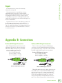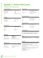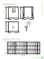
1
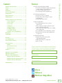
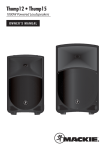
Thump18S 1200W 18" Powered Subwoofer OWNER’S MANUAL Thump18S Powered Subwoofer Important Safety Instructions 1. 2. 3. 4. 5. 6. 7. Read these instructions. Keep these instructions. Heed all warnings. Follow all instructions. Do not use this apparatus near water. Clean only with a dry cloth. Do not block any ventilation openings. Install in accordance with the manufacturer’s instructions. 8. Do not install near any heat sources such as radiators, heat registers, stoves, or other apparatus (including amplifiers) that produce heat. 9. Do not defeat the safety purpose of the polarized or grounding-type plug. A polarized plug has two blades with one wider than the other. A grounding-type plug has two blades and a third grounding prong. The wide blade or the third prong are provided for your safety. If the provided plug does not fit into your outlet, consult an electrician for replacement of the obsolete outlet. 10.Protect the power cord from being walked on or pinched particularly at plugs, convenience receptacles, and the point where they exit from the apparatus. 11.Only use attachments/accessories specified by the manufacturer. 12.Use only with a cart, stand, tripod, bracket, or table specified PORTABLE CART WARNING by the manufacturer, or sold with the apparatus. When a cart is used, use caution when moving the cart/apparatus combination to avoid injury from tip-over. 13.Unplug this apparatus during lightning storms or when unused for long periods of time. 14.Refer all servicing to qualified service personnel. Servicing is required when the apparatus has been damaged in any way, such as power-supply cord or plug is damaged, liquid has been spilled or objects have fallen into the apparatus, the apparatus has been exposed to rain or moisture, does not operate normally, or has been dropped. 15.This apparatus shall not be exposed to dripping or splashing, and no object filled with liquids, such as vases or beer glasses, shall be placed on the apparatus. 16.Do not overload wall outlets and extension cords as this can result in a risk of fire or electric shock. 17.This apparatus has been designed with Class-I construction and must be connected to a mains socket outlet with a protective earthing connection (the third grounding prong). 18.This apparatus has been equipped with a rocker-style AC mains power switch. This switch is located on the rear panel and should remain readily accessible to the user. 19.The MAINS plug or an appliance coupler is used as the disconnect device, so the disconnect device shall remain readily operable. CAUTION RISK OF ELECTRIC SHOCK! DO NOT OPEN! CAUTION: TO REDUCE THE RISK OF ELECTRIC SHOCK DO NOT REMOVE COVER (OR BACK). NO USER-SERVICEABLE PARTS INSIDE. REFER SERVICING TO QUALIFIED PERSONNEL. The lightning flash with arrowhead symbol within an equilateral triangle is intended to alert the user to the prescence of uninsulated “dangerous voltage” within the product’s enclosure, that may be of significant magnitude to constitute a risk of electric shock to persons. 20. NOTE: This equipment has been tested and found to comply with the limits for a Class B digital device, pursuant to part 15 of the FCC Rules. These limits are designed to provide reasonable protection against harmful interference in a residential installation. This equipment generates, uses, and can radiate radio frequency energy and, if not installed and used in accordance with the instructions, may cause harmful interference to radio communications. However, there is no guarantee that interference will not occur in a particular installation. If this equipment does cause harmful interference to radio or television reception, which can be determined by turning the equipment off and on, the user is encouraged to try to correct the interference by one or more of the following measures: • Reorient or relocate the receiving antenna. • Increase the separation between the equipment and the receiver. • Connect the equipment into an outlet on a circuit different from that to which the receiver is connected. • Consult the dealer or an experienced radio/TV technician for help. CAUTION: Changes or modifications to this device not expressly approved by LOUD Technologies Inc. could void the user's authority to operate the equipment under FCC rules. 21.This apparatus does not exceed the Class A/Class B (whichever is applicable) limits for radio noise emissions from digital apparatus as set out in the radio interference regulations of the Canadian Department of Communications. ATTENTION — Le présent appareil numérique n’émet pas de bruits radioélectriques dépassant las limites applicables aux appareils numériques de class A/de class B (selon le cas) prescrites dans le réglement sur le brouillage radioélectrique édicté par les ministere des communications du Canada. 22.Exposure to extremely high noise levels may cause permanent hearing loss. Individuals vary considerably in susceptibility to noise-induced hearing loss, but nearly everyone will lose some hearing if exposed to sufficiently intense noise for a period of time. The U.S. Government’s Occupational Safety and Health Administration (OSHA) has specified the permissible noise level exposures shown in the following chart. According to OSHA, any exposure in excess of these permissible limits could result in some hearing loss. To ensure against potentially dangerous exposure to high sound pressure levels, it is recommended that all persons exposed to equipment capable of producing high sound pressure levels use hearing protectors while the equipment is in operation. Ear plugs or protectors in the ear canals or over the ears must be worn when operating the equipment in order to prevent permanent hearing loss if exposure is in excess of the limits set forth here: Duration, per day in hours 8 6 4 3 2 1.5 1 0.5 0.25 or less Sound Level dBA, Slow Response Typical Example 90 92 95 97 100 102 105 110 115 Duo in small club Subway Train Very loud classical music Greg screaming at Troy about deadlines Loudest parts at a rock concert The exclamation point within an equilateral triangle is intended to alert the user of the prescence of important operating and maintaining (servicing) instructions in the literature accompanying the appliance. WARNING — To reduce the risk of fire or electric shock, do not expose this apparatus to rain or moisture. Laite on liitettävä suojakoskettimilla varustettuun pistorasiaan. Apparatet må tilkoples jordet stikkontakt. Apparaten skall anslutas till jordat uttag. Correct disposal of this product: This symbol indicates that this product should not be disposed of with your household waste, according to the WEEE directive (2012/19/EU) and your national law. This product should be handed over to an authorized collection site for recycling waste electrical and electronic equipment (EEE). Improper handling of this type of waste could have a possible negative impact on the environment and human health due to potentially hazardous substances that are generally associated with EEE. At the same time, your cooperation in the correct disposal of this product will contribute to the effective usage of natural resources. For more information about where you can drop off your waste equipment for recycling, please contact your local city office, waste authority, or your household waste disposal service. 2 Thump18S Powered Subwoofer Important Safety Instructions................................... 2 Contents.................................................................. 3 Features.................................................................. 3 Introduction............................................................. 4 How To Use This Manual.......................................... 4 Getting Started........................................................ 4 Things To Remember................................................. 4 Hookup Diagrams..................................................... 5 Thump18S Subwoofer: Rear Panel Features............... 9 1. Power Connection.......................................... 9 2. Power Switch................................................ 9 2. Power LED..................................................... 9 4. XLR Inputs.................................................... 9 5. High Pass Outputs....................................... 10 6. Full Range Outputs....................................... 10 7. Level Knob / OL LED.................................... 11 8. Normal / Invert Switch [Polarity]................. 11 Questionairre......................................................... 11 Final Thoughts....................................................... 11 Placement.............................................................. 12 Care and Maintenance............................................ 12 The Ins and Outs of Polarity................................... 12 Protection Circuitry................................................ 13 Limiting........................................................... 13 Overexcursion Protection................................. 13 Thermal Protection........................................... 13 AC Power.............................................................. 13 Appendix A: Service Information............................. 14 Appendix B: Connections ........................................ 15 Appendix C: Technical Information........................... 16 Thump18S Subwoofer Dimensions..................... 17 Thump18S Subwoofer Frequency Response........ 17 Thump18S Subwoofer Block Diagram................ 18 Features • 1200W of Room-Shaking Low End • Professional band-pass design for maximum output and deep, room-filling lows • 18" custom high-output woofer • Cool-running Class-D amplification • Total System Optimization • Precision crossover (140 Hz) • Tuning filters deliver highly accurate bass response • Robust system protection Owner’s Manual Contents • Application Flexible • Dual XLR inputs for mono or stereo applications • Stereo high-pass outputs optimize sound when connecting top boxes • Stereo full-range outputs perfect for adding more subwoofers • User-adjustable level and polarity controls • Easily mount your full-range loudspeaker via pole cup • Solid All-Wood Design • Robust all-wood enclosure with high-durability finish • “Built-Like-A-Tank” construction • 82 lb / 37.2 kg Please write the serial number here for future reference (i.e., insurance claims, tech support, return authorization, make dad proud, etc.) Purchased at: Date of purchase: Limited Warranty................................................... 19 Like us Follow us Watch our dang videos Part No. SW1050 Rev. A 03/14 ©2014 LOUD Technologies Inc. All Rights Reserved. Owner’s Manual 3 Thump18S Powered Subwoofer Introduction Getting Started The Thump18S 1200W 18" Powered Subwoofer features a professional band-pass design that delivers class-leading output and deep, room-filling lows. Designed by the world’s leader in portable live sound, the Thump18S provides ample power for high-output applications, bringing your Thump or SRM system to an entirely new level. The following steps will help you set up the subwoofers quickly. A full set of professional input and output connections provide simple integration and sonic optimization of any system. Plus, there’s ample system protection in place to protect your investment. With tons of power and a high-output/deep punch band-pass design, the Thump18S is the perfect subwoofer to complete your professional PA. 1. Make all initial connections with the power switches OFF on all equipment. Make sure the master volume, level, or gain controls are all the way down. 2. Connect the line-level outputs from the mixing console (or other signal source) to the XLR inputs on the rear panel of the Thump18S subwoofers. 3. Connect the high pass outputs from the Thump18S subwoofers to the inputs of powered loudspeakers (or to an amplifier powering passive loudspeakers). 4. Connect the supplied AC power cords to the IEC sockets on the rear panel of each subwoofer. Plug the other end into an AC outlet properly configured with the correct voltage as indicated below the IEC socket. 5. Turn the mixer (or other signal source) on. 6. Turn the subwoofers on. 7. Turn the loudspeakers on. 8. Start the signal source and raise the mixer’s main L/R fader up until audio may be heard. 9. Adjust the master volume of the mixer to a comfortably loud listening level. Things to Remember: How to Use This Manual: After this introduction, a getting started guide will help you get things set up fast. The hookup diagrams show some typical setups, while the remaining sections provide details of the Thump18S subwoofer. This icon marks information that is critically important or unique to the subwoofer. For your own good, read and remember them. • Never listen to loud music for prolonged periods. Please see the Safety Instructions on page 2 for information on hearing protection. • As a general guide, the mixer (or other signal source) should be turned on first, Thump18S subwoofers next, and loudspeakers last. As such, the loudspeakers should also be turned off first, followed by the subwoofers, then the mixer. This will reduce the possibility of any turn-on or turn-off thumps and other noises generated by any upstream equipment from coming out of the speakers. • Save the shipping boxes and packing materials! You may need them someday. Besides, the cats will love playing in them and jumping out at you unexpectedly. Remember to pretend like you are surprised! • Save your sales receipt in a safe place. 4 Thump18S Powered Subwoofer Owner’s Manual Hookup Diagrams MIC MIC MIC MIC (UNBALANCED) L L TAPE IN TAPE OUT R R 1 LINE HI-Z 2 3/4 BAL / UNBAL LINE/HI-Z IN 1 LINE IN 2 LINE IN 3 5/6 (MONO) (MONO) L L BAL / UNBAL LINE IN 5 INSERT INSERT U IC GAIN M U -20dB U IC GAIN M LEVEL SET U -20dB +50 +30dB GAIN HI 12kHz HI 12kHz MID 2.5kHz MID 2.5kHz OO +15 +15 U OO +15 FX +15 U OO +15 FX PAN +15 U OO +15 FX PAN LOW 80Hz AUX U MON OO MON OO +15 U OO +15 FX PAN 125 -15 +15 AUX U MON OO 15 15 250 500 1K 2K MAIN MIX MON MID 2.5kHz -15 +15 AUX U MON OO FX PAN 48V 0 5 10 4K POWER MAIN METERS 0dB=0dBu OL 15 10 6 3 0 2 4 7 10 20 30 USB FX PRESETS 01 BRIGHT ROOM 02 WARM LOUNGE 03 SMALL STAGE 04 WARM THEATER 05 WARM HALL 06 CONCERT HALL 07 PLATE REVERB 08 CATHEDRAL 09 CHORUS 10 CHORUS + REV 11 DOUBLER 12 TAPE SLAP 13 DELAY 1 (300ms) 14 DELAY 2 (380ms) 15 DELAY 3 (480ms) 16 REVERB + DLY (250ms) PAN 8K EQ IN BYPASS -15 +15 U LOW 80Hz -15 +15 AUX U MON HI 12kHz PHANTOM POWER 5 5 10 -15 +15 U MID 2.5kHz LOW 80Hz -15 +15 AUX +15 U PHONES 15 10 0 EQ U -15 +15 U FOOTSWITCH R MAIN OUT 15 10 5 GAIN HI 12kHz -15 +15 U LOW 80Hz LOW 80Hz -15 +15 U -15 +15 U MID 2.5kHz -15 +15 U -15 +15 U U HI 12kHz BAL / UNBAL FX SEND STEREO GRAPHIC EQ -20 +20 EQ L BAL / UNBAL MON SEND R ST RETURN LOW CUT 100Hz -15 +15 U BAL / UNBAL LINE IN 8 LEVEL SET BAL / UNBAL L BAL / UNBAL R GAIN U (MONO) L +50 EQ U -15 +15 U -15 +15 U U LOW CUT 100 Hz EQ U C GAIN MI LEVEL SET +50 GAIN LOW CUT 100 Hz EQ OO U GAIN LOW CUT 100 Hz U C GAIN MI LEVEL SET +50 +30dB (MONO) LINE IN 7 LINE IN 6 LINE IN 4 PROFESSIONAL MIC/LINE MIXER WITH FX 7/8 BAL / UNBAL R R U OO PRESETS +20 INPUT LEVEL L R MUTE USB THRU U BREAK (MUTES ALL CHANNELS) U U OL L L R MUTE dB 10 R L MUTE OL dB 10 L R MUTE OL 1 dB 10 R L MUTE OL 2 dB 10 R OO OL 5/6 dB 10 +15 FX MASTER MUTE OL 3/4 OO +15 OO FX TO MON MUTE OL 7/8 dB 10 ST RTN dB 10 FX RTN MAX OO +20 PHONES TAPE LEVEL MON MAIN dB 10 dB 10 5 5 5 5 5 5 5 5 5 U U U U U U U U U 5 5 5 5 5 5 5 5 5 10 10 10 10 10 10 10 10 10 20 20 20 20 20 20 20 20 20 30 30 30 30 30 30 30 30 30 40 50 60 40 50 60 40 50 60 40 50 60 40 50 60 40 50 60 40 50 60 40 50 60 40 50 60 OO OO OO OO OO OO OO OO OO In this example, a Thump18S subwoofer is connected to two Thump12 loudspeakers. It is a perfect setup for a small club. Here, the L/R outputs of a ProFX8 mixer are connected directly to the channel A and B inputs of a single Thump18S subwoofer. The channel A and B high pass outputs of the Thump18S subwoofer are connected directly to the inputs of each Thump12 loudspeaker. Small Club System Owner’s Manual 5 Thump18S Powered Subwoofer Hookup Diagrams continued... MONITOR OUT USB R 2 L Y X MIC PR E ON BAL /UNBAL 1 Y X MIC PR E ON BAL/UNBAL Perhaps you’re a DJ playing bumpin’ tunes in the middle of the night to a crowd that’s groovin’ and dancin’ to your fine selection. In this example, a laptop is connected to the channel 1 and 2 inputs of an Onyx Blackjack and a set of headphones are connected to the phones jack. The L/R monitor outputs of the Onyx Blackjack are connected directly to the channel A inputs of each Thump18S subwoofer. The channel A high pass output of each Thump18S subwoofer is connected directly to the input of each Thump15 loudspeaker. DJ System 6 Thump18S Powered Subwoofer To next Thump18S subwoofer input Main Outs To next Thump18S subwoofer input Owner’s Manual Hookup Diagrams continued... DL1608 Mixer Thump18S subwoofers may be daisy-chained via the male XLR connector labeled “FULL RANGE”. Simply plug the signal source (i.e., mixer output) into the input jack(s), and patch that subwoofer’s full range jack to the next subwoofers’s input jack, and so on, daisy-chaining multiple Thump18S subwoofers. See above for a visual representation of daisy-chaining. Daisy-Chaining Multiple Thump18S Subwoofers Owner’s Manual 7 Thump18S Powered Subwoofer Hookup Diagrams continued... Here’s how to set up a large club system. In this example, the L/R outputs of a DL1608 mixer are connected directly to the channel A inputs of two Thump18S subwoofers. The channel A full range outputs of these two Thump18S subwoofers are connected directly to the channel A inputs of another set of Thump18S subwoofers. Talk about beefy low end...and we’ve only connected the subs! The channel A high pass outputs of the last two Thump18S subwoofers are connected directly to the inputs of the main pair of Thump12 loudspeakers. The aux 1 and aux 2 sends from the mixer are connected directly to the inputs of a pair of Thump15 loudspeakers to be used as monitors for the band. Large Club System 8 Thump18S Powered Subwoofer 3 8 7 3.Power LED When the power switch is turned on – and the power cord is connected to an active AC mains supply – this LED illuminates green to indicate that the subwoofer is indeed really on. The cool green LED on the front of the subwoofer works the same way. 4.XLR Inputs 4 5 6 Balanced XLR female connectors are provided for the left and right inputs. Connect the full-range line-level signal from the mixer (or other signal source) to these input jacks. Owner’s Manual Thump18S Subwoofer: Rear Panel Features If you are connecting a single subwoofer output, or LFE (low-frequency effects) output to the subwoofer, you may use either the A or B input connector. NEVER connect the output of an amplifier directly to the input of the subwoofer. This could damage the input circuitry of the active subwoofer. 2 They are wired as follows, according to standards specified by the AES (Audio Engineering Society): 1 Balanced XLR Input Connector 1.Power Connection This is a standard 3-prong IEC power connector. Connect the detachable power cord (included in the packaging with the subwoofer) to the power receptacle, and plug the other end of the power cord into an AC outlet. Make sure that the AC power is matched to the AC power indicated on the rear panel (below the IEC receptacle). Disconnecting the plug’s ground pin is dangerous. Don’t do it! 2.Power Switch Pin 1 – Shield (ground) Pin 2 – Positive (+ or hot) Pin 3 – Negative (– or cold) 2 SHIELD HOT COLD 3 1 3 1 SHIELD COLD 2 HOT Balanced XLR Input Connector For more information on these connectors, see Appendix B on page 15. Press the top of this rocker switch inwards to turn on the subwoofer. Press the bottom of this rocker switch inwards to turn off the subwoofer. As a general guide, the mixer (or other signal source) should be turned on first, Thump18S subwoofers next, and loudspeakers last. As such, the loudspeakers should also be turned off first, followed by the subwoofers, then the mixer. This will reduce the possibility of any turn-on or turn-off thumps and other noises generated by any upstream equipment from coming out of the speakers. Owner’s Manual 9 Thump18S Powered Subwoofer Thump18S Subwoofer: Rear Panel Features continued... 8 7 5 6 Connect the full range outputs to the inputs of another powered subwoofer, powered loudspeakers, or to an amplifier powering passive loudspeakers. Balanced XLR male connectors are provided for the line-level A and B full range outputs. The signal at these outputs is a direct copy of the input signals. These outputs allow you to daisy-chain multiple subwoofers and/or send the full range signals to loudspeakers. It’s a great way to add side fills, too! The level control and polarity switch have no effect on the full range outputs. The outputs are separate and maintain the stereo separation of the input signals. They are wired as follows, according to standards specified by the AES (Audio Engineering Society): 5. High Pass Outputs Balanced XLR Output Connector Typically, full-range loudspeakers are connected to the high pass outputs to “split” the work with the Thump18S subwoofer. The subwoofer handles all of the low frequencies and the loudspeakers handle the rest. As a result, it is more efficient and a bit louder. Balanced XLR male connectors are provided for the line-level A and B high pass outputs. The subwoofer’s crossover splits the input signals into two frequency bands. The low frequency range below 140 Hz goes to the internal amplifier that powers the subwoofer. The frequency range above 140 Hz is sent to these line-level output jacks. Pin 1 – Shield (ground) Pin 2 – Positive (+ or hot) Pin 3 – Negative (– or cold) SHIELD COLD 3 HOT 1 2 1 3 SHIELD COLD 2 HOT Balanced XLR Output Connector The level control and polarity switch have no effect on the high pass outputs. The outputs are separate and maintain the stereo separation of the input signals. See page 7 to learn more about daisy-chaining Thump18S subwoofers. They are wired as follows, according to standards specified by the AES (Audio Engineering Society): For more information on these connectors, see Appendix B on page 15. Balanced XLR Output Connector Pin 1 – Shield (ground) Pin 2 – Positive (+ or hot) Pin 3 – Negative (– or cold) SHIELD COLD 3 HOT 1 2 1 3 SHIELD COLD 2 Balanced XLR Output Connector 10 6. Full Range Outputs Thump18S Powered Subwoofer HOT 7. Level Knob / OL LED Questionnaire The level knob adjusts the input sensitivity of the inputs. This allows signals from the outside world to be adjusted to run through each channel at optimal internal operating levels. There is –6 dB of gain with the knob fully down (off), ramping up to 6 dB of gain fully up (max). The level control has no effect on the high pass outputs or full range outputs. There is quite a bit of blank space left over, so why not fill it with a questionnaire? • Beatles or Stones? • Star Wars or Star Trek? • Chocolate or vanilla? The accompanying OL (overload) indicator illuminates red when the amplifier in the Thump18S is near the clipping point. It is OK if the OL LED blinks occasionally, because this means that the transient peaks are just reaching the maximum output of the amplifier and you are getting the most out of the subwoofer. • Batman or Superman? However, if the OL LED is blinking frequently or continuously, turn down the level control on the Thump18S or turn down the signal at its source (e.g., the mixing console) until the OL LED blinks occasionally or not at all. • Playstation or Xbox? 8. Normal/Invert Switch [Polarity] • What is your favorite color? Owner’s Manual Thump18S Subwoofer: Rear Panel Features continued... • Dogs or cats? • Beer or whiskey? • Pizza or cheeseburger? • Football or baseball? • Jimmy Page or Jimi Hendrix? • Family Guy or South Park? • Coffee or tea? This switch reverses the polarity of the signal going into the subwoofer amplifier by 180˚. It has no effect on the signal at the outputs. • What is the air-speed velocity of an unladen swallow? There is no right or wrong setting for this switch. Listen to the overall blend of the subwoofer with the rest of the system and select the switch position that gives you the best sound for your audience. In fact, your system may vary when positioned differently and in alternate venues. Don’t be afraid to experiment with the position of the polarity switch. See page 12 for more information. Final Thoughts The following pages discuss Thump18S placement, an in-depth look at polarity, protection circuitry, technical information and much more. Check it out! Owner’s Manual 11 Thump18S Powered Subwoofer Placement The Ins and Outs of Polarity The Thump18S subwoofer is designed to sit on the floor or stage. It is not designed to be pole-mounted or suspended. Thump18S subwoofers include a switch that allows you to quickly invert the polarity of the subwoofer’s output relative to the input signal it is receiving from the mixer or other sound source. But what exactly does that mean? A subwoofer works by literally pumping air as the woofer cone moves in and out with respect to the cabinet in which it is housed. It does so according to the low-frequency portion of the signal it receives from the sound source. When pole-mounting loudspeakers, be sure that the Thump18S subwoofers are stabilized and secured from falling over or being accidentally pushed over. For stacked scenarios, it is highly suggested that straps are utilized. Failure to follow these precautions may result in damage to the equipment, personal injury, or death. The cabinet has no rigging points and is not suitable for rigging. NEVER attempt to suspend an Thump18S subwoofer by its handles. As with any powered components, protect them from moisture and extreme cold and follow the other Care and Maintenance suggestions below. Care and Maintenance Your Thump18S subwoofers will provide many years of reliable service if you follow these guidelines: • Avoid exposing the subwoofers to moisture. If they are set up outdoors, be sure they are under cover if rain is expected. • Avoid exposure to extreme cold (below freezing temperatures). If you must operate the subwoofers in a cold environment, warm up the voice coils slowly by sending a low-level signal through them for about 15 minutes prior to high-power operation. • Use a dry cloth to clean the cabinets. Only do this when the power is turned off. Avoid getting moisture into any of the openings of the cabinet, particularly where the drivers are located. The woofer cone is simply following the waveform as seen in the sine wave in Figure 1. As the sine wave rises, the woofer cone pushes out. Likewise, as the sine wave falls, the woofer cone pulls into the cabinet. A musical signal is much more complex, of course, but the same principle applies. Movement of the woofer cone causes air pressure changes that we perceive as sound. When the normal/invert [polarity] switch is engaged, the original waveform is simply reversed 180˚ [see Figure 2]. Again, the subwoofer cone follows the waveform. However, this time the woofer cone starts by pulling into the cabinet followed by the woofer cone pushing out. If you have ever experimented with a subwoofer polarity switch, you may not have noticed any changes to the sound regardless of its position, especially if you are listening to just the subwoofer. This is normal, as our ears perceive them both at the same time. The normal/invert [polarity] switch comes into play when the Thump18S subwoofer is paired with a loudspeaker. Ideally, the woofer cones of the subwoofer and full range loudspeaker would work together by pushing and pulling in unison. Thump18S subwoofers are designed to be used in a broad range of applications. The flexibility provided by the polarity switch is necessary to ensure that you are receiving the best possible sound from your system, regardless of your setup. Polarity Waveforms Figure 1: Normal [0˚] Figure 2: Invert [180˚] 12 Thump18S Powered Subwoofer <–– Time ––> Amplitude Amplitude <–– Time ––> Thermal Protection The Thump18S subwoofer employs a built-in limiter for less distortion at peak levels. Additional protection includes automatic thermal shutdown should the amp overheat. However, with Class-D amp technology, which is highly-efficient, this should never be a problem. All amplifiers produce heat. The Thump18S is designed to be efficient both electrically and thermally. The protection circuits are designed to protect the subwoofers under reasonable and sensible conditions. Should you choose to ignore the warning signs [e.g. excessive distortion], you can still damage the speaker in the Thump18S by overdriving it past the point of amplifier clipping. Such damage is beyond the scope of the warranty. When the amplifier has cooled down to a safe operating temperature, the thermal switch resets itself, and the Thump18S subwoofer resumes normal operation. Limiting The driver has its own compression circuit which helps protect it from damaging transient peaks. The compressor is designed to be transparent and is not noticeable under normal operating conditions. Overexcursion Protection A subsonic filter circuit just prior to the power amplifier prevents ultra-low frequencies from being amplified. Excessive low-frequency energy can damage the woofer by causing it to “bottom out,” also know as overexcursion, which is equivalent to a mechanical form of clipping. In the unlikely event of the amplifier overheating, a built-in thermal switch will activate, muting the signal. Owner’s Manual Protection Circuitry If the thermal switch activates, try turning down the level control a notch or two on the mixing console (or the back of the subwoofer) to avoid overheating the amplifier. Be aware that direct sunlight and/or hot stage lights may be the culprit of an amplifier overheating. AC Power Be sure the Thump18S subwoofer is plugged into an outlet that is able to supply the correct voltage specified for your model. It will continue to operate at lower voltages, but will not reach full power. Be sure the electrical service can supply enough amperage for all the components connected to it. We recommend that a stiff (robust) supply of AC power be used because the amplifiers place high current demands on the AC line. The more power that is available on the line, the louder the speakers will play and the more peak output power will be available for a cleaner, punchier bass. A suspected problem of “poor bass performance” is often caused by a weak AC supply to the amplifiers. Never remove the ground pin on the power cord or any other component of the Thump18S subwoofer. This is very dangerous. Owner’s Manual 13 Thump18S Powered Subwoofer Appendix A: Service Information If you think your Thump18S has a problem, please check out the following troubleshooting tips and do your best to confirm the problem. Visit the Support section of our website (www.720trees.com) where you will find lots of useful information such as FAQs and other documentation. You may find the answer to the problem without having to part with your subwoofer. Troubleshooting No power • Our favorite question: Is it plugged in? Make sure the AC outlet is live [check with a tester or lamp]. • Our next favorite question: Is the power switch on? If not, try turning it on. • Make sure the line cord is securely seated in the line cord socket and plugged all the way into the AC outlet. • Is the power LED on the front and rear panel illuminated? If not, make sure the AC outlet is live. If so, refer to “No sound” below. • The internal AC line fuse may be blown. This is not a user serviceable part. If you suspect the AC line fuse is blown, please see the "Repair" section next. No sound • Is the level knob for the input source turned all the way down? Verify that all the volume controls in the system are properly adjusted. Look at the level meter to ensure that the mixer is receiving a signal. • Is the signal source working? Make sure the connecting cables are in good repair and securely connected at both ends. Make sure the output level control on the mixing console is turned up sufficiently to drive the inputs of the speaker. • Make sure the mixer does not have a mute on or a processor loop engaged. If you find something like this, make sure the level is turned down before disengaging the offending switch. • Has it shut down? Make sure there is at least six inches of free space behind each Thump18S subwoofer. 14 Thump18S Powered Subwoofer Poor bass performance • Check the polarity of the connections between the mixer and the subwoofers. You may have your positive and negative connections reversed at one end of one cable, causing one subwoofer to be out-of-phase with the other. • Poor bass performance may be the result of bad AC power. See the section titled ‘AC Power’ on the previous page for further details. Poor sound • Is it loud and distorted? Make sure that you’re not overdriving a stage in the signal chain. Verify that all level controls are set properly. • Is the input connector plugged completely into the jack? Be sure all connections are secure. Noise • Make sure all connections to the active subwoofers are good and sound. • Make sure none of the signal cables are routed near AC cables, power transformers, or other EMI-inducing devices. • Is there a light dimmer or other SCR-based device on the same AC circuit as the Thump18S? Use an AC line filter or plug the subwoofer into a different AC circuit. Hum • Try disconnecting the cable connected to the input jack. If the noise disappears, it could be a “ground loop,” rather than a problem with the Thump18S subwoofer. Try some of the following troubleshooting ideas: • Use balanced connections throughout your system for the best noise rejection. • Whenever possible, plug all the audio equipment’s line cords into outlets which share a common ground. The distance between the outlets and the common ground should be as short as possible. Owner’s Manual Repair For warranty service, refer to the warranty information on page 19. Non-warranty service is available at a factoryauthorized service center. To locate the nearest service center, visit www.720trees.com, click “Contact Tech Support” and select “Locate a Service Center or Distributor” [3]. Service for Thump18S subwoofers outside the United States can be obtained through local dealers or distributors. If you do not have access to our website, you may call the Tech Support department at 1-800-898-3211, Monday-Friday, during normal business hours, Pacific Time, to explain the problem. Tech Support will tell you where the nearest factory-authorized service center is located in your area. Appendix B: Connections Balanced XLR Input Connector Balanced XLR Output Connector Each Thump18S subwoofer has two female XLR inputs. Be sure the cables are wired per AES (Audio Engineering Society) standards: There are also four male balanced XLR output connectors on each Thump18S subwoofer [two high pass and two full range]. Be sure the cables are wired per AES (Audio Engineering Society) standards: Balanced XLR Input Connector Pin 1 – Shield (Ground) Pin 2 – Positive (+ or hot) Pin 3 – Negative (– or cold) Balanced XLR Output Connector Pin 1 – Shield (Ground) Pin 2 – Positive (+ or hot) Pin 3 – Negative (– or cold) 2 SHIELD HOT COLD 3 SHIELD 1 1 3 SHIELD COLD 3 HOT Balanced XLR Input Connector HOT 2 1 COLD 2 1 3 SHIELD COLD 2 HOT Balanced XLR Output Connector Thump18S subwoofers may be daisy-chained via the male XLR connector labeled “FULL RANGE”. Simply plug the signal source (i.e., mixer output) into the input jack(s), and patch that subwoofer’s full range jack to the next subwoofer’s input jack, and so on, daisy-chaining multiple Thump18S subwoofers. See page 7 for a visual representation of daisy-chaining. Owner’s Manual 15 Thump18S Powered Subwoofer Appendix C: Technical Information Thump18S Subwoofer Specifications Acoustic Performance: Safety Features Frequency Response (–3 dB) 40 Hz – 120 Hz Frequency Response (–10 dB) 30 Hz – 132 Hz Max peak SPL 130 dB Crossover Point 140 Hz Slope Input Protection Peak and RMS limiting, power supply and amplifier thermal protection Display LEDs Front and rear power ON, Rear OL limiter 2nd order HP, 6th order LP Construction Features Transducer Cabinet Woofer Diameter 18 in / 457 mm Voice Coil Diameter 3.0 in / 76 mm Cone MaterialPaper Exterior grade 15 mm plywood Finish Textured black catalyzed polyurethane paint Handles One on each side Magnet MaterialFerrite Physical Properties Height 26.5 in / 672 mm Power Amplifier Width 22.6 in / 573 mm Rated Power 600 watts rms 1200 watts peak Depth 22.8 in / 580 mm Weight 82 lb / 37.2 kg Rated THD < 1% CoolingConvection DesignClass D Mounting Methods The Thump18S subwoofer is designed to sit on the floor or stage. It is NOT designed to be pole-mounted or suspended. The cabinet has no rigging points and is not suitable for rigging. Never attempt to suspend the Thump18S by its handles. Input/Output Input Type Female XLR balanced Input Impedance 20 k balanced, 20 k unbalanced Options Thump18S Cover P/N 2036809-25 Full Range Outputs Male XLR balanced SPM200 Loudspeaker Pole Mount P/N 2035170-01 High Pass Outputs Male XLR impedance balanced Disclaimer Line Input Power US detachable line cord 100 – 120 VAC, 50 – 60 Hz, 150W EU detachable line cord 220 – 240 VAC, 50 – 60 Hz, 150W AC Connector 3-pin IEC 250 VAC, 10 A male Power Supply Type Switchmode Since we are always striving to make our products better by incorporating new and improved materials, components, and manufacturing methods, we reserve the right to change these specifications at any time without notice. The “Running Man” figure is a registered trademark of LOUD Technologies Inc. All other brand names mentioned are trademarks or registered trademarks of their respective holders, and are hereby acknowledged. ©2014 LOUD Technologies Inc. All Rights Reserved. 16 Thump18S Powered Subwoofer Owner’s Manual Thump18S Subwoofer Dimensions 26.5 in 672 mm 26.5 in 672 mm 22.8 in 580 mm 22.6 in 573 mm WEIGHT 82 lb 37.2 kg 22.8 in 580 mm 22.6 in 573 mm Thump18S Subwoofer Frequency Response +10 dB 0 dB –10 dB –20 dB 10 100 1000 10000 20000 Frequency (Hz) Owner’s Manual 17 18 Thump18S Powered Subwoofer High Pass Output XLRs Input XLRs Full Range Output XLRs Crossover HPF Crossover HPF LPF Crossover HPF Overexcursion Protection - 6dB +6dB LEVEL Gain Inverted Normal Polarity Invert Thermal Mute Thermal Monitoring Limiter OL LED Amp Thump18S Powered Subwoofer Thump18S Subwoofer Block Diagram Please keep your sales receipt in a safe place. This Limited Product Warranty (“Product Warranty”) is provided by LOUD Technologies Inc. (“LOUD”) and is applicable to products purchased in the United States or Canada through a LOUD-authorized reseller or dealer. The Product Warranty will not extend to anyone other than the original purchaser of the product (hereinafter, “Customer,” “you” or “your”). For products purchased outside the U.S. or Canada, please visit www.720trees.com to find contact information for your local distributor, and information on any warranty coverage provided by the distributor in your local market. Owner’s Manual Limited Warranty LOUD warrants to Customer that the product will be free from defects in materials and workmanship under normal use during the Warranty Period. If the product fails to conform to the warranty then LOUD or its authorized service representative will at its option, either repair or replace any such nonconforming product, provided that Customer gives notice of the noncompliance within the Warranty Period to the Company at: www.720trees.com or by calling LOUD technical support at 1.800.898.3211 (toll-free in the U.S. and Canada) during normal business hours Pacific Time, excluding weekends or LOUD holidays. Please retain the original dated sales receipt as evidence of the date of purchase. You will need it to obtain any warranty service. For full terms and conditions, as well as the specific duration of the Warranty for this product, please visit www.720trees.com. The Product Warranty, together with your invoice or receipt, and the terms and conditions located at www.720trees.com constitutes the entire agreement, and supersedes any and all prior agreements between LOUD and Customer related to the subject matter hereof. No amendment, modification or waiver of any of the provisions of this Product Warranty will be valid unless set forth in a written instrument signed by the party to be bound thereby. Need help with the subwoofer? • Visit www.720trees.com and click Support to find: FAQs, manuals, addendums, and other documents. • Email us at: [email protected]. • Telephone 1-800-898-3211 to speak with one of our splendid technical support chaps (Monday through Friday, normal business hours, Pacific Time). Owner’s Manual 19 16220 Wood-Red Road NE Woodinville, WA 98072 • USA Phone: 425.487.4333 Toll-free: 800.898.3211 Fax: 425.487.4337 www.720trees.com