1
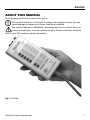
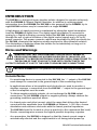
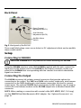
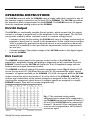
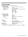
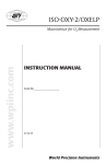
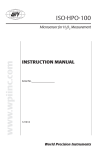
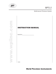
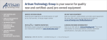
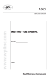
DLS100 Stimulus Isolator
www.wpiinc.com
For use with DS8000 Digital Stimulator
INSTRUCTION MANUAL
Serial No._____________________
121009
CAUTION: DS8000 must be
powered off before DLS100 is
attached.
World Precision Instruments
DLS100
Contents
About this Manual....................................................................................................................... 1
Introduction................................................................................................................................... 2
Notes and Warnings..................................................................................................................... 2
General Notes............................................................................................................................ 2
Parts List............................................................................................................................................ 3
Unpacking........................................................................................................................................ 3
Instrument Description........................................................................................................... 4
Instrument Description................................................................................................................ 4
Front Control Panel................................................................................................................. 4
Bottom End Panel.......................................................................................................................... 5
Top End Panel............................................................................................................................ 5
Back Panel.................................................................................................................................. 6
Setup ................................................................................................................................................. 6
Connecting to DS8000........................................................................................................... 6
Connecting the Output........................................................................................................... 6
Operating Instructions............................................................................................................ 7
DLS100 Output................................................................................................................................ 7
DLS Control...................................................................................................................................... 7
Quick Functional Check............................................................................................................... 8
Adjusting the DC Offset............................................................................................................... 9
Disabling Audible Alarm...................................................................................................... 10
Optional Accessories............................................................................................................... 10
Troubleshooting........................................................................................................................ 11
Specifications................................................................................................................................. 12
Index.................................................................................................................................................... 13
Warranty......................................................................................................................................... 15
Claims and Returns..................................................................................................................... 15
Repairs............................................................................................................................................. 15
Copyright © 2009 by World Precision Instruments, Inc. All rights reserved. No part of this publication
may be reproduced or translated into any language, in any form, without prior written permission of
World Precision Instruments, Inc.
World Precision Instruments
iii
iv
World Precision Instruments
DLS100
About this Manual
The following symbols are used in this guide:
This symbol indicates a CAUTION. Cautions warn against actions that can
cause damage to equipment. Please read these carefully.
This symbol indicates a WARNING. Warnings alert you to actions that can
cause personal injury or pose a physical threat. Please read these carefully.
NOTES and TIPS contain helpful information.
Fig. 1–DLS100
World Precision Instruments
1
Introduction
The DLS100 is a biological linear stimulus isolator designed to operate exclusively
with the DS8000 8-Channel Digital Stimulator. In addition to receiving signal
information from the DS8000, the DLS100 is also powered by the DS8000. Up to
eight DLS100 isolators may be connected to a single DS8000.
A high degree of signal precision is maintained by taking the signal information
from the DS8000 in digital form. The digital signal information is converted to
analog by a Digital-to-Analog converter within the DLS100. Isolation is achieved
through the use of optical isolation of the digital control signals and a DC-to-DC
power converter. This power converter, which was developed by WPI specifically for
the DLS100, eliminates the batteries usually employed in other stimulus isolators.
The elimination of batteries allows the isolator to run indefinitely as long as it is
connected with the DS8000.
Notes and Warnings
WARNING! Electric Shock Hazard! The DLS100 is capable of
producing hazardous voltages in excess of 100 Volts. Use
care not to create electrically exposed open connections to
the DLS100 so that you don’t come into contact with the
output voltage. It is up to the user to ensure safe connections.
CAUTION: DS8000 MUST be powered off before attaching the DLS100.
General Notes
•
If a monitoring device is connected to the DLS100, the “–” output of the DLS100
must always be connected to the ground input of the monitoring device.
•
In applications where a bio-amplifier and electrodes are used to monitor a
stimulus response, a connection from the DLS100 “–” output to the ground input
of the bio-amplifier must be made.
•
To obtain negative polarity outputs, do not exchange the DLS100 output
connections. Set the DS8000 output for negative polarity. Always observe the
grounding conditions specified above.
•
For lowest noise and offset current, select the range that delivers the desired
current with the amplitude from the DS8000 set between 1–10V. Also, choose
stimulation and reference electrodes with the lowest practical impedance.
•
The DLS100 should be located as close as practical to the experiment (the load).
Shorter connecting wires ensures the highest possible frequency response.
•
As a precaution, the DLS100 is designed so that the lowest current range is
automatically selected and the output switch is off during initial power up.
2
World Precision Instruments
DLS100
Parts List
After unpacking, verify that there is no visible damage to the instrument. Verify that
all items are included:
(1) DLS100
(1) Instruction Manual
(1) Accessory kit, including
(1) 2033 Black insulated miniature banana plug
(1) 2034 Red insulated miniature banana plug
(1) 3142 Mini banana adapter
(1) 83016 DS8000 cable
(1) 83017 10KW Dummy load test resistor
(1) 610023 Potentiometer adjustment tool
Unpacking
Upon receipt of this instrument, make a thorough inspection of the contents and
check for possible damage. Missing cartons or obvious damage to cartons should be
noted on the delivery receipt before signing. Concealed damage should be reported
at once to the carrier and an inspection requested. Please read the section entitled
“Claims and Returns” on page 15 of this manual. Please contact WPI Customer Service
if any parts are missing at 941.371.1003 or [email protected].
Returns: Do not return any goods to WPI without obtaining prior approval (RMA
# required) and instructions from WPI’s Returns Department. Goods returned
(unauthorized) by collect freight may be refused. If a return shipment is necessary,
use the original container, if possible. If the original container is not available, use a
suitable substitute that is rigid and of adequate size. Wrap the instrument in paper
or plastic surrounded with at least 100mm (four inches) of shock absorbing material.
For further details, please read the section entitled “Claims and Returns” on page 15 of
this manual.
World Precision Instruments
3
Instrument Description
Instrument Description
Front Control Panel
The DLS100 control panel is shown Fig. 2.
Output Connection
Output Button
Activity LED
Alarm LED
Constant Current Controls
Constant Voltage Controls
Range LEDs
Range Buttons
Power LED
Fig. 2–DLS100 front panel
Range Buttons and Range LEDs–Select the operating range by pressing one of
the range buttons. They are marked according to the full-scale current or voltage
available. The adjacent Range LED indicator illuminates to indicate the selected
range. The full-scale value of the selected current or voltage output range is
delivered when the signal level from the DS8000 is 10V. The polarity of the output
4
World Precision Instruments
DLS100
current or voltage corresponds directly to the polarity of the output signal from the
DS8000.
Power LED–The Power LED indicator illuminates when the DLS100 is connected to a
DS8000 and the DS8000 is powered on.
Activity LED–The Activity LED indicator illuminates whenever a digital signal is
received from the DS8000.
Alarm LED– The Alarm LED indicator illuminates whenever the DLS100 is in
constant current mode and unable to deliver the requested current. If the audible
alarm is enabled, an alarm sounds simultaneously. For more information, see
“Troubleshooting” on page 11.
Bottom End Panel
Fig 3–Bottom end panel of the DLS100
Input Connector–The input connector on the bottom end panel accepts the DLS100
interface cable (WPI # 83016), which may be connected to any of the 9-pin output
connectors on the back of the DS8000.
Top End Panel
Fig 4–Top end panel of the DLS100
Output Connectors–The output connectors are “miniature banana” jacks on the
top end panel (Fig. 4). Mating miniature banana plugs are included in the accessory
kit (WPI #2033, 2034) The red “+” connector must always be connected to the
stimulation electrode. The black “–“ connector must be connected to the reference
electrode and to the ground connection of the monitoring system.
On/Off Push button switch–This output button controls an output relay which
connects/disconnects the signal from the output terminal. The button illuminates
when the output is connected to the red terminal.
World Precision Instruments
5
Back Panel
Even Channel
Adjustment (POT1)
Odd Channel
Adjustment (POT2)
Audible Alarm
Switch
Fig. 5–Back panel of the DLS100
Three small black plugs cover access holes for DC adjustment offsets and an audible
alarm enable switch.
Setup
Connecting to DS8000
CAUTION: DS8000 MUST be powered off before attaching the DLS100.
Using the DS8000 interface cable (WPI #83016) supplied with the unit, connect the
Input port on the bottom end of the DLS100 to the Output connector on the rear
panel of the DS8000 that corresponding with the channel from which stimulation
signals are desired.
Connecting the Output
The DLS100 accessory kit includes several connectors that provide options for
connecting to the output. The 2033 and 2034 color-coded, single-pole, mini banana
connectors or the 3142 double-pole, mini banana connectors are used to connect
output wires. The optional 501670 dual mini-banana to BNC adaptor can be used to
convert the mini banana sockets on the DLS100 output into a standard female BNC
connector.
NOTE: When making a connection with coaxial cable (WPI #2851, BNC, 5-ft long),
use the 501670 Dual Mini-Banana-to-BNC adapter. See “Optional Accessories” on
page 10.
6
World Precision Instruments
DLS100
Operating Instructions
The DLS100 connects with the DS8000 using a single cable that connects to any of
the channel output connectors on the back of the DS8000. The DLS100 reproduces
the waveform that is programmed on the DS8000. The DLS100 sources its signals
from the combined analog matrix on the DS8000.
DLS100 Output
The DLS100 is a continually variable (linear) isolator, which means that the output
current or voltage is proportional to the amplitude of the input signal. The DLS100
can provide output in either constant current or constant voltage mode.
•
Constant current–In this setting, the DLS100 will vary its voltage continuously to
maintain a fixed level of current to the preparation. In the event that more than
100V is required to generate the desired current, a non-compliance alarm will
sound (if it’s enabled) to alert you that the experimental current requirements
are not met.
•
Constant voltage–The output voltage of the DLS100 tracks to the digital signal
from the DS8000.
DLS Control
The DS8000 control panel is the primary control center of the DLS100. Signal
waveshape, amplitude, timing and gating or triggering are all controlled from the
DS8000. Controls on the DLS100 are limited to a set of amplitude range selector
buttons and an output disconnect switch.
The DS8000 combined analog (CA) matrix assignment screen (Fig. 6) shows A1-A8
across the top and CA1-CA8 down the left side. A1-A8 represent the eight “virtual
channels” of signals available in the DS8000. CA1-CA8 correspond with the DLS100
output connectors which are labeled 1-8 on the back of the DS8000. A DLS100 can
receive any combination of the virtual channels as assigned in the CA matrix by
checking the assignment check boxes. If multiple signals are assigned to a single
DS8000 channel, they will be summed algebraically.
Fig. 6–The combined analog matrix
assignment screen shown left is configured to
send DS8000 signals from virtual channels A1,
A3 and A4 to the DLS100 that is connected to
channel 1. Channels 3-8 are configured with
a one-to-one correspondence, and channel 2
receives no signal.
World Precision Instruments
7
Quick Functional Check
To demonstrate the DLS100 and DS8000 are working as desired, complete the
following exercise.
CAUTION: DS8000 MUST be powered off before attaching the DLS100.
1.
Connect the DLS100 to any channel on the DS8000.
2.
Connect the 10KW “Dummy Load,” included in the Accessory Kit, to the DLS100
output.
3.
Connect an oscilloscope to the dummy load resistor.
NOTE: The ground lead of the oscilloscope probe MUST connect to the “–”
output of the DLS100.
4.
Turn power on to the DS8000. The Power LED and the 1µA range indicator on
the DLS100 illuminate.
5.
Press the 1mA range key. The 1mA indicator illuminates.
6.Refer to the DS8000 manual to set up the selected channel of the DS8000 for a
continuous uni-polar pulse, 1ms width, 5ms period, and 1V amplitude.
7.
Set the DS8000 output to on. The Activity LED on the DLS100 illuminates,
indicating that a signal is being received. The oscilloscope should not show any
signal on the load yet, because the Output switch on the top panel is not yet on.
8.
Press the On/Off (yellow) switch once. The switch button illuminates and a 1V
positive pulse should be observed on the oscilloscope.
TECHNICAL NOTE: The amplitude is 1V because the DS8000 is sending a 1V
signal to the DLS100, and the 1mA full scale range is selected. Since a 10V
signal is required to produce a full scale output, a 1V signal produces 10% of
full scale, or 100µA output. From Ohm’s Law, (E = I×R), 100µA through a 10KW load
produces 1V.
9.
Set the amplitude of the pulse from the DS8000 to 10V. The pulse observed on
the oscilloscope should be 10V, also.
10. Press the 100µA range switch on the DLS100. The pulse amplitude on the
oscilloscope should drop to 1V.
11. Set the pulse amplitude on the DS8000 to –10V. The output of the DLS100
should now be –1V.
You may try other signal waveforms, such as a sine wave. Or, you can program
different waveforms on other DS8000 channels and move the interface cable to
these other channels, one at a time, to see the DLS100 output change according to
which channel it is connected.
8
World Precision Instruments
DLS100
Adjusting the DC Offset
The DLS100 DC offset must be adjusted for both the even and odd channels. Adjust
the even channels first, because they are subject to the adjustment of the odd
channels. This calibration involves two potentiometers. POT1 is for even channels
on the DS8000, and POT2 is for odd channels.
CAUTION: DS8000 MUST be powered off before attaching the DLS100.
1.
Connect the DLS100 to the DS8000 channel 2 output (9-pin connection).
2.
Power on the DS8000.
3.
On the DS8000, program channel 2 in DC mode for 0.00V amplitude. Select
both the Run and Output check boxes on the DS8000 panel.
4.
Plug the 10KW dummy test resistor (WPI #83017) into the Output (red and black
mini-banana connectors) to the top of the DLS100.
5.
Set the DLS100 to the current range you intend to use by pressing the desired
Range button. The 1mA range is sufficient. The 10mA range may also be used,
but it is much more difficult to adjust to zero.
6.
Press the On/Off button to turn the DLS100 output on. Allow the unit to warm
up for 30 minutes before adjustment continues.
7.
Turn the DLS100 face down and remove the two black plugs covering POT1 and
POT2 (Fig. 7).
Even Channel
Adjustment (POT1)
Odd Channel
Adjustment (POT2)
Audible Alarm
Switch
Fig. 7–POT1 and POT2 are located on the underside of the DLS100 and are covered by
small black plugs
8.
Use a high quality digital volt meter with a scale greater than 20MW. Set the
meter in the millivolt scale and monitor the output voltage at the top of the load
resistor.
World Precision Instruments
9
9.
Using the provided adjustment tool (WPI #610023), carefully adjust POT1 until
the meter reads 0.00mV ±1mV.
10. Turn off the DS8000 and connect the DLS100 to the DS8000 channel 1 output
(9-pin connection).
11. Power on the DS8000 and bring up the channel 1 menu. Verify that channel 1
is set to Run and the Output is on. The output must be set to 0.00 amplitude.
12. With a digital volt meter set in the millivolt scale, monitor the output voltage of
the load resistor.
13. Using the provided adjustment tool (WPI #610023), carefully adjust POT2 until
the meter reads 0.00mV ±1mV.
14.Repeat this procedure for both channels to achieve the best zero balance.
15.Reinstall the two, small, black plugs.
Disabling Audible Alarm
If desired, the audible alarm may be disabled. The switch is accessible through a
small hole on the back of the unit (Fig. 7).
1.
Three black plugs are located on the back panel of the DLS100. Remove the
center black plug covering the audible alarm switch.
2.
Use a #1 or #0 Phillips screwdriver to rotate the switch counter-clockwise to
disable the audible alarm.
Optional Accessories
Table 1: Accessories
Part Number
2851
501670
83016
610023
503301
10
Description
BNC, 5-ft long
Dual Mini-Banana-to-BNC
Replacement DS8000-to-DLS100 Cable
Potentiometer adjustment tool
Cable, mini-DIN extension, 10’
World Precision Instruments
DLS100
Troubleshooting
Non-compliance
alarm sounding
No signal output (activity light off)
DLS has no power
Issue
Possible Cause
Solution
Poor cable connection
Check connections between the DS8000
and the DLS100. If necessary, reseat the
cable in the socket.
Bent pin on 9-pin connector on
the DLS100 cable
Examine the 9-pin connector. Carefully
straighten any bent pins. If any pin is
missing, replace the cable (WPI #83016).
Yellow DLS100 On/Off switch is
set to off
Press the yellow button on the DLS100
Green output switch on the
DS8000 is set to off
Set the output switch to on
DS8000 software “Run” check
box is not selected for the
appropriate channel
On the DS8000 screen, verify that
the Run and Output check boxes are
selected for the channel your DLS100 is
connected with
The appropriate channel check
box is not selected in the matrix
assignment screen on the
DS8000
Check the matrix assignment screen and
verify that the correct check boxes are
selected for the channel you are using.
See “DLS Control” on page 7.
Yellow DLS100 On/Off switch is
set to off
Press the yellow button on the DLS100
Open output circuit
Check the integrity of all the connections
in your preparation
DC offset is greater than 20mV
Adjust the DC offset. See “Adjusting the
DC Offset” on page 9.
NOTE: If you have a problem/issue with that falls outside the definitions of this
troubleshooting section, contact the WPI Technical Support team at 941.371.1003 or
[email protected].
World Precision Instruments
11
Specifications
The DLS100 conforms to the following specifications:
Current Source Mode
Full-scale* Current
10mA, 1mA, 100µA, 10µA, 1µA, bipolar
Compliance Voltage
± 100V
Output Impedance
Greater than 100MW
LinearityBetter than 0.05% of full-scale range setting
A/C Noise FloorRange Value
10mA ≥1µA
1mA
≥0.5µA
100µA ≥0.3µA
10µA ≥0.3µA
1µA
≥0.3µA
Voltage Source Mode
Full-scale* Voltage
± 100V
Maximum Current
10mA
Output Impedance
Less than 1W
LinearityBetter than 0.05% of full-scale range
setting
A/C Noise FloorRange Value
100V ≥20mV
10V
≥10mV
Isolation
Resistance
Capacitance
Dimensions
Output Terminal
Connecting Cable
Greater than 1000MW
Less than 0.01µF, from output terminals to
DS8000 and earth ground
14 x 9 x 3.5 cm (5.5 x 3.5 x 1.5 in.)
Mini-banana jacks
183cm (6’)
* A 10V signal from the DS8000 produces a full-scale output from the DLS100.
12
World Precision Instruments
DLS100
Index
Symbols
2033 3
2034 3
3142 3
83016 3, 6
83017 3
A
accessories 10
alarm 10
audible alarm 5, 10
P
parts list 2
R
range buttons 4
returns 3
S
signal waveforms 8
sine wave 8
sockets 6
specifications 12
B
banana 5
banana sockets 6
batteries 2
bio-amplifier 2
T
troubleshooting 11
C
cable 6
coaxial cable 6
combined analog matrix 7
connectors 6
control panel 4, 7
V
virtual channels 7
U
unpacking 3
D
DC adjustment offsets 6
DC offset 9
Digital-to-Analog converter 2
F
functional check 8
I
input connector 5
M
matrix assignment screen 7
mini banana sockets 6
N
negative polarity outputs 2
noise 2
O
offset current 2
Ohm’s Law 8
optical isolation 2
output connectors 5
World Precision Instruments
13
14
World Precision Instruments
DLS100
Warranty
WPI (World Precision Instruments, Inc.) warrants to the original purchaser that this equipment, including its components and parts, shall be free from defects in material and workmanship for a period
of one year* from the date of receipt. WPI’s obligation under this warranty shall be limited to repair
or replacement, at WPI’s option, of the equipment or defective components or parts upon receipt
thereof f.o.b. WPI, Sarasota, Florida U.S.A. Return of a repaired instrument shall be f.o.b. Sarasota.
The above warranty is contingent upon normal usage and does not cover products which have been
modified without WPI’s approval or which have been subjected to unusual physical or electrical stress
or on which the original identification marks have been removed or altered. The above warranty will
not apply if adjustment, repair or parts replacement is required because of accident, neglect, misuse,
failure of electric power, air conditioning, humidity control, or causes other than normal and ordinary
usage.
To the extent that any of its equipment is furnished by a manufacturer other than WPI, the foregoing
warranty shall be applicable only to the extent of the warranty furnished by such other manufacturer.
This warranty will not apply to appearance terms, such as knobs, handles, dials or the like.
WPI makes no warranty of any kind, express or implied or statutory, including without limitation any
warranties of merchantability and/or fitness for a particular purpose. WPI shall not be liable for any
damages, whether direct, indirect, special or consequential arising from a failure of this product to
operate in the manner desired by the user. WPI shall not be liable for any damage to data or property
that may be caused directly or indirectly by use of this product.
Claims and Returns
Inspect all shipments upon receipt. Missing cartons or obvious damage to cartons should be noted
on the delivery receipt before signing. Concealed loss or damage should be reported at once to the
carrier and an inspection requested. All claims for shortage or damage must be made within ten
(10) days after receipt of shipment. Claims for lost shipments must be made within thirty (30) days
of receipt of invoice or other notification of shipment. Please save damaged or pilfered cartons until
claim is settled. In some instances, photographic documentation may be required. Some items are
time-sensitive; WPI assumes no extended warranty or any liability for use beyond the date specified
on the container
Do not return any goods to us without obtaining prior approval and instructions from our Returns
Department. Goods returned (unauthorized) by collect freight may be refused. Goods accepted for
restocking will be exchanged or credited to your WPI account. Goods returned which were ordered
by customers in error are subject to a 25% restocking charge. Equipment which was built as a special
order cannot be returned.
Repairs
Contact our Customer Service Department for assistance in the repair of apparatus. Do not return
goods until instructions have been received. Returned items must be securely packed to prevent further damage in transit. The Customer is responsible for paying shipping expenses, including adequate
insurance on all items returned for repairs. Identification of the item(s) by model number, name, as
well as complete description of the difficulties experienced should be written on the repair purchase
order and on a tag attached to the item.
* Electrodes, batteries and other consumable parts are warranted for 30 days only from the date on which the
customer receives these items.
World Precision Instruments
15
World Precision Instruments, Inc.
USA
International Trade Center, 175 Sarasota Center Blvd., Sarasota FL 34240-9258
Tel: 941-371-1003 • Fax: 941-377-5428 • E-mail: [email protected]
UK
Astonbury Farm Business Centre • Aston, Stevenage, Hertfordshire SG2 7EG
Tel: 01438-880025 • Fax: 01438-880026 • E-mail: [email protected]
Germany
Zossener Str. 55, 10961 Berlin
Tel: 030-6188845 • Fax: 030-6188670 • E-mail: [email protected]
Japan
Physio-Tech Co., Ltd.
1-6-3 Iwamoto-cho, Chiyoda-ku, Tokyo 100-0032
Tel: 81-3-3864-2781 • Fax: 81-3-3864-2787 • E-mail: [email protected]
Australia
Coherent Life Sciences Pty. Ltd.
116 Sir Donald Bradman Dr • Hilton, South Australia 5033
Tel: (03) 9887-6262 • Fax: (03) 9887-9585 • E-mail: [email protected]
China & Hong Kong
WPI Shanghai Trading Co., Ltd.
Rm 20a, No8 Dong Fang Rd., Lu Jia Zui Financial District, Shanghai PRC
Tel: +86 688 85517 • E-mail:[email protected]
Internet
www.wpiinc.com