1
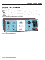
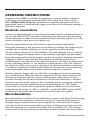
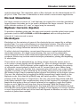
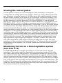
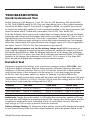
A365
www.wpiinc.com
Stimulus Isolator
INSTRUCTION MANUAL
Serial No._____________________
120514
World Precision Instruments
WARNING! High voltages produced can produce dangerous electrical
shock. This device is not approved for clinical applications. Do not turn on
power while you are holding bare high voltage wires or connectors.
Stimulus Isolator (A365)
CONTENTS
ABOUT THIS MANUAL ..................................................................................................................... 1
INTRODUCTION .................................................................................................................................. 2
Parts List ........................................................................................................................................... 2
Unpacking ....................................................................................................................................... 3
INSTRUMENT DESCRIPTION .......................................................................................................... 4
Controls ............................................................................................................................................ 4
Audible Alarms............................................................................................................................... 4
OPERATING INSTRUCTIONS........................................................................................................... 6
Electrode connections ................................................................................................................. 6
Microstimulation ........................................................................................................................... 6
Normal Stimulation ...................................................................................................................... 7
Biphasic Currents (bipolar) ......................................................................................................... 7
Electrolysis ...................................................................................................................................... 7
Viewing the current pulses ........................................................................................................ 8
Monitoring Current on a Data Acquisition system (Lab-Trax 4/16) ............................ 8
Monitoring Voltage on a Data Acquisition system (Lab-Trax 4/16) ............................ 9
Constant Voltage Operation ..................................................................................................... 9
Instrument Case Grounding (Earthing) ................................................................................10
Electrode Exhauster ....................................................................................................................10
Low Battery Indication ..............................................................................................................10
MAINTENANCE..................................................................................................................................11
Charging the NiMH Battery Stack (A365R) ........................................................................11
Full Charge or Partial Charge ..................................................................................................11
The A362 Charger ......................................................................................................................11
Replace Batteries Annually ......................................................................................................11
Changing the Batteries..............................................................................................................11
Procedure .......................................................................................................................................12
Expected Battery Life .................................................................................................................12
TROUBLESHOOTING .......................................................................................................................13
Quick Instrument Test ................................................................................................................13
Detailed Test .................................................................................................................................13
Calibration .....................................................................................................................................14
SPECIFICATIONS ................................................................................................................................15
DECLARATION OF CONFORMITY...............................................................................................16
WARRANTY ........................................................................................................................................19
Claims and Returns ....................................................................................................................19
Repairs ............................................................................................................................................19
Copyright © 2014 by World Precision Instruments, Inc. All rights reserved. No part of this publication
may be reproduced or translated into any language, in any form, without prior written permission of
World Precision Instruments, Inc.
World Precision Instruments
iii
iv
World Precision Instruments
Stimulus Isolator (A365)
ABOUT THIS MANUAL
The following symbols are used in this guide:
This symbol indicates a CAUTION. Cautions warn against actions that can
cause damage to equipment. Please read these carefully.
This symbol indicates a WARNING. Warnings alert you to actions that can
cause personal injury or pose a physical threat. Please read these carefully.
NOTES and TIPS contain helpful information.
Fig. 1—A365 Stimulus Isolator
World Precision Instruments
1
INTRODUCTION
The A365 is a specialized stimulus isolator for use in neuroscience and muscle
studies. Battery operated and electrically isolated from ground, its quiet internal
control circuitry minimizes artifacts and has very low leakage specifications. Stimulus
isolation is needed to assure the precise localization of stimulus current and to
prevent current flow from the stimulation site to ground. Two models are available:
A365D is powered by sixteen 9-volt alkaline transistor batteries; A365R is powered
by 16 rechargeable NiMH (nickel metal hydride) 9-volt cells (A362 battery charger
required). These instruments can pulse repetitively at rates and durations controlled
by front panel controls and/or be optically pulsed or gated for time durations of
a few microseconds to DC, by any pulse generator, D-to-A or interface unit which
can provide an adequate output voltage equal to or greater than the threshold
command levels specified below.
Because current threshold is the most quantitatively reproducible parameter for
stimulation of nerve and muscle, all WPI stimulus isolators are designed to supply
constant current. Model A365 dispenses current reproducibly from its output
terminals, the amplitude being determined by the selected current range and the
setting of the % of Range dial. Current amplitude is “constant”, that is, load resistance
independent, provided that the I x R (load) product does not exceed the available
battery supply voltage. An audible alarm (the compliance alarm) will sound if I x R
reaches this limit. Model A365D can generate a voltage of 135V or more across
its output terminals. The amplitude of the current will be as dialed as long as the
voltage drop across the load (stimulus electrode path) does not reach the magnitude
of the supply voltage. The compliance alarm would then sound, signifying that (a)
too much current was dialed for a given load or (b) inter-electrode resistance was
too high or the electrode circuit path was open (see the Quick Instrument Test,
below).
WARNING! High voltages produced can produce dangerous electrical
shock. This device is not approved for clinical applications. Do not turn on
power while you are holding bare high voltage wires or connectors.
Parts List
After unpacking, verify that there is no visible damage to the sensor. Verify that all
items are included:
(1) A365 Stimulus Isolator
(1) Instruction Manual
2
World Precision Instruments
Stimulus Isolator (A365)
Unpacking
Upon receipt of this instrument, make a thorough inspection of the contents and
check for possible damage. Missing cartons or obvious damage to cartons should be
noted on the delivery receipt before signing. Concealed damage should be reported
at once to the carrier and an inspection requested. Please read the section entitled
“Claims and Returns” on page 19 of this manual. Please contact WPI Customer Service
if any parts are missing at 941.371.1003 or [email protected].
Returns: Do not return any goods to WPI without obtaining prior approval (RMA
# required) and instructions from WPI’s Returns Department. Goods returned
(unauthorized) by collect freight may be refused. If a return shipment is necessary,
use the original container, if possible. If the original container is not available, use a
suitable substitute that is rigid and of adequate size. Wrap the instrument in paper
or plastic surrounded with at least 100mm (four inches) of shock absorbing material.
For further details, please read the section entitled “Claims and Returns” on page 19 of
this manual.
World Precision Instruments
3
INSTRUMENT DESCRIPTION
Controls
INPUT: An external command voltage level of approximately 5 volts (TTL) applied
to this connector enables current flow from the OUTPUT. Do not apply a continuous
DC input voltage greater than 9 volts.
DC/TEST: Current can be manually generated by toggling this switch. MOM
(momentary) position allows push-release operation. ON provides a sustained DC
output on the output connectors.
AUDIO: When the AUDIO switch is on, an audible tone will sound whenever a
stimulus current is being generated. A higher pitched audible signal will also sound,
independent of the AUDIO switch, if the OUTPUT voltage amplitude approaches that
of the battery power stack (the “compliance alarm”). A low frequency tone indicates
the batteries need replacement or recharging.
MODE: When this switch is set on Bipolar, every pulse applied to the input will cause
the polarity of the output current to reverse. Thus, any sequence of pulses applied
results in alternating plus and minus current pulses at the output terminals. In the Off
position, pulse polarity will be as indicated by the red polarity lamps above the red
and black output terminals.
POLARITY SELECT: A polarity reversing push button switch sets the red or black
OUTPUT terminal to be positive. The polarity lamps will toggle from red to black in
the bipolar mode as they are being switched.
RANGE: 0.1, 1 or 10 milliamperes can be selected as a maximum current.
% OF RANGE: This variable ten turn digital indicator control sets the exact current
amplitude as a percentage of the selected maximum current selected by the Range
switch. For ranges below 5% (05.0), it is recommended to use fixed 0.1% test
resistors and a digital meter to set and check the required current values.
OUTPUT: Current output terminals. Output voltage depends on load resistance. An
audible warning sounds when the maximum load voltage occurs. When the Output
switch is Off, the output terminals are disconnected from the circuitry.
POWER ON/OFF: Switch connects battery power to the isolator.
Turn the power switch off when instrument is not in use to avoid battery drain.
Audible Alarms
Audio on — This is a high frequency tone to indicate stimulation is present.
High tone with Audio off — compliance alarm, this indicates that the A365 cannot
supply enough voltage to drive the requested “dialed-up” current through the test
4
World Precision Instruments
Stimulus Isolator (A365)
subject. This is usually an indication of a broken cable, electrode disconnection or a
misplaced electrode. Warning, the maximum high voltage is present on the banana
connectors.
Low tone — Battery low alarm; batteries require replacement or recharging. This
alarm turns on when the high voltage stack reaches 90 volts and depending on
the experiment’s current requirements the A365 may only supply power for a
short duration (less than half an hour at 10 mA with NiMH). This is at the 6.0 volt
threshold of the NiMH battery and rapid voltage decay in the battery cell occurs
after this point. NiMH batteries that have decayed below 5.5V (82.5V in A365) may
not be further rechargeable and require replacement. Disposable alkaline batteries
may be discharged longer (two hours at 10 mA) to 5.0 volts or less (75 volts on
A365), however this not recommended as the cessation of the stimulation is not
predictable.
World Precision Instruments
5
OPERATING INSTRUCTIONS
Operation of the A365 is controlled by applying an external voltage command
to the input or by manually operating the DC/Test switch. Any source such as
WPI’s DS8000, A300, A310 pulse generators or equivalent generator will be an
appropriate source of command and trigger sync pulses for oscilloscope viewing of
bioelectric responses.
Electrode connections
Connect an appropriate pair of stimulating electrodes from the experimental site to
the red and black OUTPUT terminals, respectively. Any conductive wire (including
carbon wire) may be affixed to the terminals by either a banana plug (4 mm) or by
means of holding a bare wire on the plastic nut.
Keep the output switch in the OFF position to avoid accidental stimulation.
During the powering of any electronic circuit either up or down, the output may be
unstable due to internal oscillations or circuits powering at different times.
Turn the output switch to OFF. Turn POWER to ON. Select Biphasic Off (i.e., unipolar
current) and toggle the Polarity Select. A red indicator lamp lights over the output
electrode terminal which will be positive (usually, the negative electrode stimulates).
Toggling the AUDIO switch ON will allow the user to hear the advent of the
command pulse; normally this is left in the OFF position. Turn the % of Range knob
to zero and Range switch to 1 mA. Switch the Output switch to ON. This connects
the electrodes to the current source. Arriving at an optimal stimulation current level
is usually an empirical procedure in which the user increases the current gradually
from sub-threshold values until a desired stimulus response is achieved.
Always toggle the Output switch to OFF while connecting electrodes or powering
up or down the unit. When this switch is toggled to OFF, the output terminals are
disconnected from the stimulus current source and the current source is short
circuited internally (see Electrode Exhauster) if the Electrode Exhauster is enabled.
Check the accuracy of the setting on the % of Range dial by connecting a milliamp
meter directly across the output connectors and pushing the DC/TEST switch.
The direction of current flow is determined by which output connector has been
designated as the anode, i.e., RED + or BLACK + on the POLARITY switch. AUDIO
monitoring of the pulses can be switched ON or OFF at the user’s option.
Microstimulation
Microstimulation is considered to be stimulation currents of less than 500 μA passing
through electrodes and tissues. Currents in excess of 1 mA have been known to
damage tungsten metal electrodes by burning the tip of the electrode. Tungsten
and other metal electrodes are made by an electro-etching process that leaves the
electrode behaving as a capacitor (AC) rather than a conductor (DC). This etching
action results in the formation of an electrolytic interface between the metal surface
6
World Precision Instruments
Stimulus Isolator (A365)
and the electrolyte. The capacitive value of this electrode can be characterized as 0.2
pF/μ2 at 1 Khz. This form of stimulation is best suited to neuroscience applications.
Normal Stimulation
For larger currents in excess of 1 mA that may be required for muscular stimulation,
larger surface electrodes are to be used to distribute the larger currents. The use of
silver-chloride surfaces (0.1 mm2 or larger) may be necessary.
Biphasic Currents (bipolar)
To produce a biphasic pulse pair, the user must provide a double pulse from a pulse
generator (such as WPI’s DS8000 or A310 Accupulser) with an inter-pulse time
interval of 1 microsecond or more.
Electrolysis
Electrolysis or the emission of gases at the electrode tips are caused by a voltage
greater than 2 or more volts passing in an electrolyte solution. This effect can be
minimized by increasing the conductance of the electrodes to the tissue or by
lowering the voltage below the emission threshold.
To effect electrical stimulation, current must flow across a metal-electrode/fluidelectrolyte interface. At a high current density, this can result in undesirable
electro-chemical action at the metal-electrolyte interface as well as high voltage
gradients. Effects may include metal-electrolyte polarization, plating and deplating,
or electrolysis.
These effects can be diminished by: (a) Using a larger electrode surface area so
as to reduce current density and (b) biphasic (i.e., zero net charge) stimulus current
using brief pulses. A365’s biphasic mode enables the user to alternate the polarity
of successive current pulses so that the net DC current flow is zero. When using
the biphasic mode note that the first command pulse will result in an output pulse
opposite in polarity to that indicated by the polarity lamp prior to the pulse since
the leading edge of each command pulse reverses the polarity of the output current.
The user can confirm this by toggling the MOM (momentary) switch briefly in the
Biphasic mode. Note that the polarity lamp will switch position. Therefore, if the
polarity of the first pulse is of importance, the user can preset the polarity with the
push button switch to the complementary state of that required. For example, if one
wants the first pulse at the red output terminal to be negative, toggle the Polarity
button so as to light the red lamp over the red terminal. With the receipt of the
leading edge of the first command pulse, the lamp will switch to the black terminal.
Thus the first current pulse would have a polarity of red negative. If a burst of pulses
is used, the polarity at the end of the burst will depend on whether an odd or even
number of pulses were emitted.
World Precision Instruments
7
Viewing the current pulses
To view pulses of current on an oscilloscope it is first necessary to convert the
current pulses to voltage pulses (see “Voltage”, below ) by using a dummy electrode
pair. Therefore, connect a resistor of 1 K Ohm across the output terminals. Connect
the two output terminals to the input of an oscilloscope. Oscilloscope settings: 200
mV per cm, vertical sensitivity, DC coupled and 1 millisecond per cm sweep speed.
Set the frequency of a pulse generator to 200 Hz (INTERVAL= 5 ms) and pulse
WIDTH to 1 millisecond. Set the controls as follows: RANGE to 1 mA, AUDIO to OFF,
POLARITY to RED +. Dial % of Range to maximum and turn the POWER switch to
ON. When the oscilloscope is synchronized, 1 volt pulses (5 cm on the scope) should
be observed. Note the shape and speed of the rising and falling edges; they should
be fast and smooth. The true speed of a current pulse generator can be best seen
using low values of shunt resistance, as in the example above. As the load resistance
increases to 10 KΩ and larger, the effect of shunt capacity will be to slow the rising
and falling edges of the voltage waveform. It should be noted that in connecting the
oscilloscope to view the A365 output, one output terminal usually will be connected
to ground (thus, one cannot view or measure the output waveform without compromising
A365’s isolation from ground). The stimulation voltage may be monitored by a very
high-impedance, high-voltage-input amplifier / recorder, however the extra “load”
and cable capacitance of the monitor needs to be taken into account. The input
impedance of the recorder should be greater than 1010 ohms and the input voltage
requirements of the amplifier is ±150 volts. Please note that the isolation may be
compromised.
Monitoring Current on a Data Acquisition system
(Lab-Trax 4/16)
The Lab-Trax 4/16 has a voltage input limit of 10 volts and it has a 1M ohm
impedance. The isolator output is converted from a maximum range of 200 volts
to a usable range for the DataTrax4/16. One application would be to place a 475K
ohm resistor in series with a 25K resistor. This resistor set is placed across the black
and red connectors and the monitored signal is across the 25K ohm resistor. Larger
resistor pairs may be chosen to reduce the loading effects on the measured voltages.
This circuit passes 400 microamps and measures 0–10V across the 25K resistor. The
Lab-Trax 4/16 measures the voltage and is adjusted by a 20× conversion factor. The
500K total R does draw current and this does effect the total voltage and current of
the circuit and should be noted in the log.
8
World Precision Instruments
Stimulus Isolator (A365)
Fig. 2—Location of jumpers for the electrode exhauster circuit (shown disabled).
Monitoring Voltage on a Data Acquisition system
(Lab-Trax 4/16)
To monitor the outputs as a current meter on the data acquisition system, use a
shunt R resistor in series with the current flow along one of the electrodes (red
connector).
A 5 ohm resistor will drop 50 mV at 10 mA. The data conversion factor is 200×=
10mA
A 50 ohm resistor will drop 500 mV at 10 mA. The data conversion factor is 20×=
10mA
A 500 ohm resistor will drop 5000 mV at 10 mA. The data conversion factor is 2×=
10mA
The use of the above resistors will limit the maximum voltage that the A365 can
deliver, and the current will be reduced by a proportional amount.
Constant Voltage Operation
A365 can be used as a precise voltage source by placing a precision “dummy”
resistor load across the output terminals. Precision resistors (such as the 100 Ω, 1000
Ω and 10,000 Ω resistors in WPI’s optional Dummy Load Resistor Kit #DRL) when
placed across the output terminals convert the precision current levels to accurate
voltage levels. For example, 1 milliampere flowing through 1000 Ohms will produce
1 volt across the output terminal pair. Thus, models A365D and A365R can be used
as low noise sources of accurate voltage pulses or DC. To maintain less than 1%
error, avoid shunting the output dummy resistor with a load resistance less than 100
times the dummy resistance value.
World Precision Instruments
9
Instrument Case Grounding (Earthing)
The instrument case has not been connected to any part of the internal circuit of
A365. To make a connection to the case, a spade lug and wire can be inserted under
the head of any screw on the underside of the instrument case. This is useful in
reducing noise in a Faraday cage environment.
Electrode Exhauster
The A365 is equipped with an electrode exhauster circuit. When enabled, this circuit
will place a low resistance shunt across the output connections when the isolator
is not stimulating (no TTL). This removes the excess charge on the cables and
stimulation electrodes faster that allowing that voltage to decay through the tissue.
This excess voltage is decayed in microseconds rather than a much slower decay
in milliseconds. The value of this low resistance is approximately 5 to 15 ohms. To
enable the electrode exhauster, open the A365 and locate jumper pads 1, 2 and
3 behind the current range potentiometer on the right side of the forward printed
circuit board. As indicated by the printing on the board, if the soldered wire is
between pads 2 and 3 (shorting), then the electrode exhauster is enabled; if the wire
is between pads 1 and 2, then the electrode exhauster option is disabled. The A365
is factory shipped with this feature disabled. This can be tested with a voltmeter/
ohmmeter. Turn the A365 power on, Output switch to ON. Leave the DC/Test switch
to the center OFF position and do not move it. Check that the voltage across the
banana connectors is zero (0.0) volts (to protect the ohmmeter), then check with an
ohmmeter; the resistance should be below 20 ohms.
Low Battery Indication
A low-pitched tone (the battery alarm) will sound when the A365 is powered on.
This is an indication that the batteries require replacement or recharging. This
alarm turns on when the high voltage stack reaches 90 volts and, depending on
the experiment’s current requirements, the A365 may only supply power for a short
duration (less than half an hour at 10 mA with NiMH). This is at the 6-volt threshold
of the NiMH battery and rapid voltage decay in the battery cell occurs after this
point. NiMH batteries that have decayed below 5.5V (82.5V in A365) may not be
further rechargeable and require replacement. Disposable alkaline batteries may
be discharged longer (2 hours at 10mA) to the 5.0 volt or below level (75 volts
on A365), however this not recommended as the cessation of stimulation is not
predictable.
10
World Precision Instruments
Stimulus Isolator (A365)
MAINTENANCE
Charging the NiMH Battery Stack (A365R)
To recharge the battery stack of an A365R, a companion charger, model A362, is
designed to charge the A365’s batteries rapidly and safely. The charger cable plug
inserts into the charging receptacle on the rear panel of the A365R isolator. Connect
the charger’s power cord to the power line. The POWER switch on A365R must be
OFF to enable charger operation.
Full Charge or Partial Charge
The A365R battery stack will usually recharge overnight (16 hours) from a
completely discharged state. Do not exceed 20 hours on NiMH batteries as
overheating recharge-able batteries will lessen their overall recharge life cycles. For
less than a full discharge, less time is required to obtain a full charge.
Disconnect the battery charging cable from the A365R while the instrument is
in use. This avoids the possibility that power line noise will be introduced via the
charger cable (as well as a loss of isolation). The charging rate on either the high
voltage side (A=129.5V) or the low voltage side (B= 8.00 V) is 5.00 mA. The A362
and A365R can be placed on an multi-hour electronic AC timer to provide the
correct time of the charge without loss of battery charge due to battery leakage back
into the charger when the A362 is disconnected from the mains.
The A362 Charger
The A362 Charger has two high-voltage charging circuits built into it, and is used on
a number of isolators and may use the A or B charging circuit in a manner different
than described here. Both sides of the A362 provide 175 volts and are internally
regulated to provide the correct voltage charge at 5.00 mA to the stack of batteries.
The charger should not be attached to the isolator while in use. The two outer “D”
shaped connectors are GND and the two inner circular pins are the separate positive
outputs.
Replace Batteries Annually
Rechargeable batteries should be replaced on an annual basis. If the A365R is
placed in storage for over 90 days, the batteries should be removed and stored
separately. Rechargeable batteries can and do leak KOH (potassium hydroxide), a
caustic substance which can damage the internal circuitry of the instrument.
TO PRESERVE BATTERY LIFE, TURN THE POWER SWITCH OFF WHEN INSTRUMENT
IS NOT IN USE.
Changing the Batteries
Model A365D requires 16 nine-volt alkaline batteries. Depending on load current
World Precision Instruments
11
usage, the batteries will operate satisfactorily for two months or more. Replace
batteries when required or annually. Model A365R requires 16 Nickel-Metal Hydride
9-volt batteries (7.2 volt); type IEC-6F22 or equivalent is recommended. Alkaline
batteries in model A365D cannot be replaced with NiMH rechargeable batteries as
model A365D is not equipped for charging. Do not use the higher voltage 9.6.V
rechargeable cells in this instrument.
Procedure
Turn the POWER switch to OFF. Remove four screws on the bottom of the instrument
case. Gently remove the entire internal instrument assembly from the outer case
by sliding the front panel forward. Unscrew and the remove padded cover plate
over the battery assembly. Remove this plate by lifting up and moving out the right
side of the instrument. When removing the batteries work from the front row first
on either side and firmly pull up, but without tilting the batteries excessively as not
to damage the battery clips. Insert the new batteries with firm but moderate force
to seat the battery in the clips. Match with care the male and female connectors
on the battery tops to the mating connectors on the battery printed circuit board.
When all batteries have been installed, reattach the battery cover plate and test the
instrument by repeating the “Quick Instrument Tests” outlined above. Nickel-Metal
Hydride rechargeable batteries may require an initial 16-hour charge, depending
on their condition when purchased. Reinsert the instrument assembly into the
outer case and secure the bottom screws. Take care to push the copper contacts
down when inserting the case. Nickel-Metal Hydride rechargeable batteries will
discharge by themselves on the shelf. If the A365 is to be stored for a length of
time (up to 3 months), then test the unit and either recharge the batteries or replace
them as necessary. For long term storage remove the batteries from the A365.
Nickel-Metal Hydride rechargeable batteries should last approximately one to two
years with proper care. The replacement batteries should be chosen from the same
manufacturer (and the same manufacturing lot number, if possible) to ensure equal
levels of drain.
Expected Battery Life
9V Alkaline main high voltage stack: 57 hours at 100% duty cycle 10 mA load;
428h @ 1 mA, 1200h @ 100μA.
7.2 V NiMH main high voltage stack: 14 hours at 100% duty cycle 10 mA load;
100h @ 1mA; 306h @ 100μA.
Typical duty cycles are 1 to 5% (At a full load of 10mA and at a 1% duty cycle the
A365 can last approximately 1000hours on alkaline cells, on NiMH this duration
is approxi-mately 260 hours, both are due to the 9V power circuit discharging first.
Control circuit (powered by one 9V or 7.2V battery):
Power on and not stimulating: 1000 hours ( 9 V alkaline), 260 hours (7.2 V NiMH)
12
World Precision Instruments
Stimulus Isolator (A365)
TROUBLESHOOTING
Quick Instrument Test
Switch Output to OFF, Range to 1 mA, DC/Test to OFF, Bipolar to OFF and AUDIO
to ON. Turn POWER switch to ON. One red lamp above one of the output terminals
should be lit. When the DC/Test switch is toggled to MOM, an audible tone should
be heard (an externally applied +5 volt command applied to the input connector will
have the same effect). Sound will cease when Test is OFF. Turn Audio OFF.
Push the Polarity Select button and confirm that red lamps above the red and black
terminals switch back and forth when the button is pushed. Switch DC/Test to ON. A
high-pitched tone should sound. This is the “compliance” limit alarm which sounds
when the full battery supply voltage is across the output terminal pair, for example,
when the output leads are open-circuited and a trigger signal of 5 volts is applied to
the input. Turn DC/TEST to Off. The instrument is operational.
Another quick instrument test for the battery charge level: With the power on
and a digital voltmeter across the banana connectors, switch the output to ON and
hold down the MOM key. With 9V alkaline batteries at a full charge, the voltmeter
should read 135 V or more; less than 90 V indicates low batteries. With 7.2 V NiMH
batteries a full charge, the voltmeter should read 110 V or more; if less than 90V
these should be charged (the compliance alarm should sound).
Detailed Test
Equipment required for testing: a set of precision resistors such as WPI’s DRL, and
a precision digital voltmeter that has been recently calibrated. Measure the exact
resistance of the test resistors. Place a 1K 0.1% resistor across the output terminals
and the test leads of the voltmeter. Set the range to 1 mA and range percentage
to 50.0%. Turn the power switch on, audio on, polarity to positive. When the
momentary switch is activated a tone will be heard and the DVM will read 0.50 volts
(1000 ohms × 0.0005 A = 0.50 V). On the 100 μA scale the voltage will be 0.050 V
and on the 10 mA scale the voltage will be 5.00 V.
Resistor
100 ohm
10m A scale 50%
0.50 V +/- 0.0025 V
5.00 V +/- 0.025 V
1000 ohm
50.0 V +/- 0.25 V
10,000 ohm
1m A scale 50%
0.05 V +/- 0.00025 V
0.50 V +/- 0.0025 V
5.00 V +/- 0.025 V
100 μA scale 50%
0.005 V +/- 0.000025 V
0.05 V +/- 0.00025 V
0.50 V +/- 0.0025 V
Audio tests: Toggle the audio switch to OFF while the momentary switch is ON and
the tone will stop. With the momentary switch ON, remove the resistor pack and the
compliance alarm will sound, indicating a lack of controllable current. Warning: A
high voltage of 125V or more is present across the terminals.
Battery Voltage Testing: To determine that a battery stack is fully charged and ready
to use: Remove any loads from the output terminals, place the power switch in the
World Precision Instruments
13
on position, output to positive. Place a digital voltmeter test leads on the output
terminals. Apply the momentary switch and note the output voltage.
Alkaline: An alkaline stack of batteries will measure in the 135 volt range (9V ×
15). Alkaline 9V batteries can be discharged to approximately 5.0V per battery or
80V per stack of 16. However, replacement should be indicated at the 90V point to
ensure longevity during a procedure.
Rechargeable: A full charge of NiMH batteries will indicate a voltage range greater
than 108V (7.2V × 15). A low stack of rechargeable batteries for a NiMH stack will
be less than 96V (6.0V per cell, requiring recharge). Recharging should begin when
the voltage of the stack reaches 95V to ensure longevity during a procedure.
Calibration
There is no calibration for the A365D or A365R; any exacting current requirements
should be verified by the user by using ohm’s law and a set of precision resistors and
a traceable voltmeter. The current set knob should display all zeros at the minimum
counter-clockwise position, though this does not prevent the instrument from being
externally calibrated.
NOTE: If you have a problem/issue with that falls outside the definitions of this
troubleshooting section, contact the WPI Technical Support team at 941.371.1003 or
[email protected].
14
World Precision Instruments
Stimulus Isolator (A365)
SPECIFICATIONS
This unit conforms to the following specifications:
Output Waveform ............................Current pulses or DC
Output Polarity..................................Unipolar or electronically switched bipolar
Output Current Ranges ..................0.1, 1.0 and 10 milliamperes
Current Amplitude Error ................0.5 % of full scale, max.
Current Resolution ...........................0.1% of full scale
Output Load Voltage Range.........>100 volts
External Command Volts...............+2.2 V. min., 9 V (DC continuous) max.
Current Rise Time + Delay ...........6 μs, typical. (1000 Ω load)
Current Fall Time + Delay.............10 μs, typical. (1000 Ω load)
Impedance to ground.....................1012 Ω shunted by < 15 picofarads
Isolation Max. Volts .........................2500 VAC, input to output
Leakage ...............................................less than 9 nA at full scale 10 mA
Power ...................................................Model A365D: 16 alkaline 9V batteries
Model A365R: Rechargeable NiMH (7.2 V only
(Requires A362 battery charger)
World Precision Instruments
15
DECLARATION OF CONFORMITY
16
World Precision Instruments
Stimulus Isolator (A365)
World Precision Instruments
17
18
World Precision Instruments
Stimulus Isolator (A365)
WARRANTY
WPI (World Precision Instruments, Inc.) warrants to the original purchaser that this equipment,
including its components and parts, shall be free from defects in material and workmanship for a
period of one year* from the date of receipt. WPI’s obligation under this warranty shall be limited
to repair or replacement, at WPI’s option, of the equipment or defective components or parts upon
receipt thereof f.o.b. WPI, Sarasota, Florida U.S.A. Return of a repaired instrument shall be f.o.b.
Sarasota.
The above warranty is contingent upon normal usage and does not cover products which have been
modified without WPI’s approval or which have been subjected to unusual physical or electrical stress
or on which the original identification marks have been removed or altered. The above warranty will
not apply if adjustment, repair or parts replacement is required because of accident, neglect, misuse,
failure of electric power, air conditioning, humidity control, or causes other than normal and ordinary
usage.
To the extent that any of its equipment is furnished by a manufacturer other than WPI, the foregoing
warranty shall be applicable only to the extent of the warranty furnished by such other manufacturer.
This warranty will not apply to appearance terms, such as knobs, handles, dials or the like.
WPI makes no warranty of any kind, express or implied or statutory, including without limitation any
warranties of merchantability and/or fitness for a particular purpose. WPI shall not be liable for any
damages, whether direct, indirect, special or consequential arising from a failure of this product to
operate in the manner desired by the user. WPI shall not be liable for any damage to data or property
that may be caused directly or indirectly by use of this product.
Claims and Returns
Inspect all shipments upon receipt. Missing cartons or obvious damage to cartons should be noted
on the delivery receipt before signing. Concealed loss or damage should be reported at once to the
carrier and an inspection requested. All claims for shortage or damage must be made within ten
(10) days after receipt of shipment. Claims for lost shipments must be made within thirty (30) days
of receipt of invoice or other notification of shipment. Please save damaged or pilfered cartons until
claim is settled. In some instances, photographic documentation may be required. Some items are
time-sensitive; WPI assumes no extended warranty or any liability for use beyond the date specified
on the container
Do not return any goods to us without obtaining prior approval and instructions from our Returns
Department. Goods returned (unauthorized) by collect freight may be refused. Goods accepted for
restocking will be exchanged or credited to your WPI account. Goods returned which were ordered
by customers in error are subject to a 25% restocking charge. Equipment which was built as a special
order cannot be returned.
Repairs
Contact our Customer Service Department for assistance in the repair of apparatus. Do not return
goods until instructions have been received. Returned items must be securely packed to prevent
further damage in transit. The Customer is responsible for paying shipping expenses, including
adequate insurance on all items returned for repairs. Identification of the item(s) by model number,
name, as well as complete description of the difficulties experienced should be written on the repair
purchase order and on a tag attached to the item.
* Electrodes, batteries and other consumable parts are warranted for 30 days only from the date on which the
customer receives these items.
World Precision Instruments
19
World Precision Instruments, Inc.
USA
International Trade Center, 175 Sarasota Center Blvd., Sarasota FL 34240-9258
Tel: 941-371-1003 • Fax: 941-377-5428 • E-mail: [email protected]
UK
Astonbury Farm Business Centre • Aston, Stevenage, Hertfordshire SG2 7EG
Tel: 01438-880025 • Fax: 01438-880026 • E-mail: [email protected]
Germany
Zossener Str. 55, 10961 Berlin
Tel: 030-6188845 • Fax: 030-6188670 • E-mail: [email protected]
China & Hong Kong
WPI Shanghai Trading Co., Ltd.
Rm 20a, No8 Dong Fang Rd., Lu Jia Zui Financial District, Shanghai PRC
Tel: +86 688 85517 • E-mail:[email protected]
Internet
www.wpiinc.com