1
Servi
This manual is to be used by qualified appliance
technicians only. Maytag does not assume any
responsibility for property damage or personal
injury for improper service procedures done by
an unqualified person.
This Base Manual covers general
Refer to individual
for information
information
Technical
on specific
Sheet
models
This manual includes, but is
not limited to the following:
Sli e
C
Air C
Amana
AAC081SRA
AAC101SRA
AAC121SRA
AAC141SRA
AAC182SRA
AAC202SRA
AAC242SRA
m
|
e
16022061
May 2003
important
information
important
Notices
for Servicers
and Consumers
Maytag will not be responsible for personal injury or property damage from improper service procedures. Pride and
workmanship go into every product to provide our customers with quality products. It is possible, however, that
during its lifetime a product may require service. Products should be serviced only by a qualified service technician
who is familiar with the safety procedures required in the repair and who is equipped with the proper tools, parts,
testing instruments and the appropriate service information. IT IS THE TECHNICIANS RESPONSIBLITY TO
REVIEWALL APPROPRIATE SERVICE INFORMATION BEFORE BEGINNING REPAIRS.
_lb
WARNING
I
To avoid risk of severe personal injury or death, disconnect power before working!servicing
electrical shock.
on appliance to avoid
To locate an authorized servicer, please consult your telephone book or the dealer from whom you purchased this
product. For further assistance, please contact:
Customer
Service
Support
CAIR Center
Web Site
WWW.AMANA.COM
WWW.JENNAIR.COM
WWW.MAYTAG.COM
Center
...............................................
............................................
.............................................
CAIR Center in Canada ..........................................
Amana Canada Product ..........................................
Recognize
I
Safety Symbols,
_,
DANGER--Immediate
I
_
WARNING--Hazards
I
_ll
Telephone Number
1-800-843-0304
1-800-536-6247
1-800-688-9900
1-800-688-2002
1-866-587-2002
Words, and Labels
DANGER
hazards which WILL result in severe personal injury or death.
WARNING
I
or unsafepractices
which COULD
CAUTION
result
inseverepersonalinjury
ordeath.
I
CAUTION--Hazards
or unsafe practices which COULD result in minor personal injury, product or property
damage.
2
16022061
Rev. 0
©2003
MaytagAppliancesCompany
important Safety information
General
Information
[
This Service Manual describes the operation,
disassembly, troubleshooting, and repair of Amana
Room Air Conditioners. it is intended for use by
authorized servicers who troubleshoot and repair these
units.
ill WARNING
J
To avoidriskofpersonalinjury
or deathdue toelectrical
shock, grounding wires and wires colored like grounding
wires are NOT to be used as current carrying
conductors. The standard accepted color coding for
NOTE: It is assumed that users of this manual are
ground wires is green or green with a yellow stripe.
familiar with the use of tools and equipment used Electrical components such as the compressor and fan
to troubleshoot and repair electrical, mechanical, motor are grounded through an individual wire attached
and refrigeration systems; and understand the
to the electrical component and to another part of the air
terminology used to describe and discuss them. conditioner. Grounding wires should not be removed
from individual components while servicing, unless the
Maytag urges you read and follow all safety precautions
component is to be removed and replaced. It is
and warnings contained in this manual. Failure to comply
extremely important to replace all removed grounding
with safety information may result in severe personal
wires before completing service.
injury or death.
[
Related
Publications
This is a base service manual, covering a range of
similar models. It is intended to be used in conjunction
with the Parts Manual and Technical Sheet covering
specific model being serviced.
General
Precautions
WARNING
J
To avoid risk of heat exposure, which may cause death
or severe illness, air conditioner must be monitored
when malfunctions or shuts down.
and Warnings
WARNING
]
To avoid risk of personal injury or death due to electrical
shock, disconnect electrical power to unit before
attempting to service the unit.
WARNING
]
To avoid risk of personal injury or death due to electrical
shock, DO NOT, under any circumstances, alter the
grounding plug. Air conditioner must be grounded at all
times. Do not remove warning tag from power cord. If a
two-prong (non-grounding) wall receptacle is
encountered, contact a qualified electrician and have
the receptacle replaced with a properly grounded wall
receptacle in accordance with the National Electrical
Code.
©2003 Maytag Appliances
Company
16022061
Rev. 0
3
Table of Contents
Important Information ..................................................
Important Safety Information ........................................
Product Identification ....................................................
Troubleshooting Information .........................................
Testing Procedures .....................................................
Low Voltage ...........................................................
High Voltage .........................................................
Testing Capacitors ................................................
Checking Overload Protectors .............................
Checking Compressor Windings ..........................
Ground Test .........................................................
Compressor Burnout ............................................
Fan Motor .............................................................
Leak Testing .........................................................
Brazing .................................................................
Restriction Testing ................................................
Evacuation ...........................................................
2
3
5
6
13
13
13
13
13
13
14
14
14
14
15
15
15
Charging ..............................................................
Refrigerant Precautions .......................................
Using Line Piercing Valves ...................................
Open Lines ...........................................................
Disassembly Procedures ............................................
Air Filter Removal .................................................
Insert Removal .....................................................
Front Frame Removal ..........................................
Front Frame Clips Removal .................................
Chassis Removal .................................................
Rotary Control Assembly Removal .......................
16
17
17
17
18
18
18
19
19
19
20
4
16022061
Fan MotorAssembly and Disassembly ................ 21
Condenser Removal ............................................
21
Compressor Overload Protector Removal ............ 22
Compressor Removal ..........................................
22
Evaporator (Indoor Coil) Removal ........................ 23
Appendix A
Owner's Manual ....................................................
A-1
Rev. 0
@2003
MaytagAppliancesCompany
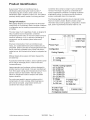
Product identification
Every Amana ® Room Air Conditioner has an
identification plate showing the model number, P
(manufacturing part) number, serial number of unit.
Identification plate is located on side of unit. Use plate to
positively identify specific model of unit being serviced.
Condenser fans contain a slinger ring for condensate
removal. The slinger ring picks-up condensate and
sprays it against the condenser, increasing condenser
evaporative cooling. In extreme humidity conditions,
excess condensate drains from base pan.
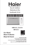
Design
The following diagram explains how to interpret Amana
Room Air model numbers. Model numbers contain
information about cooling capacity, configuration, chassis
type, power requirements and series index for unit.
information
Many design features are incorporated into all Amana ®
model Room Air Conditioners. Basic concepts of balance
in refrigeration and air handling components are used in
all models.
The outer case of unit, regardless of style, is designed to
help circulate air across evaporator, condenser,
compressor and fan motor. It must be in place to ensure
maximum efficiency of unit, to prevent overheating of
components, and to maintain system balance and
capacity.
Structural components of room air conditioners are
heavy, zinc-coated steel that is further treated with zinc
phosphate. Exterior parts are hot-dipped galvanized steel
that is chemically pretreated, then primed with electrocoated primer, and finished with a baked-on polyester top
coat.
Modular design allows easier and faster disassembly
and assembly.
Acoustical and thermal insulation, used on partition panel
and in side air discharge plenum, reduce noise and
increase efficiency.
Large evaporator and condenser coils are designed to
provide maximum heat transfer. Coils are manufactured
from rifled copper tubing and embossed aluminum fins to
achieve maximum heat transfer. Thermal mastic is
placed on refrigeration tubes to dampen and isolate
system vibrations.
Fan motors are sealed to prevent moisture and dirt
contamination of motor windings. Motor bearings are
permanently lubricated. Large blower wheels and
condenser fans reduce noise levels.
123456789
Brand
_Controt
-_
Product Type
Company
16022061
Series Index
Chassis Type
Configuration
--Voltage
Cooling Capacity
3 Configuration
C= Cooling
4-5 BTU cooling Capacity
05= 5,000 BTU
08= 8,000 BTU
10= 10,000 BTU
12= 12,000 BTU
20= 20,000 BTU
6 Voltage
1= 115 Volt
2= 230 Volt
7 Chassis Type
F= Fixed
S= Slide Out
8 Control Type
R= Rotary Knob
T= Electronic control
@2003 Maytag Appliances
Type
Rev. 0
9 Series Index
5
Troubleshooting
information
WARNING
To avoid risk of electrical shock, personal injury, or death, disconnect electrical power source to unit and
discharge capacitor through a 10,000 ohm resistor before attempting to service, unless test procedures require
power to be connected. Ensure all ground wires are connected before certifying unit as repaired and/or
operational.
CAUTION
Units covered in this manual are polarized. Reversing polarity of a unit or any of its components will cause
damage. To avoid reversing polarity, any wires disconnected or removed during service must be reconnected to
the same location. To ensure wires are reconnected to the proper location, tag or otherwise mark the wires
before disconnecting or removing.
Tools and Equipment
Troubleshooting
Accurate diagnosis and repair of malfunctioning air
conditioners requires proper tools and equipment. In
addition to standard hand tools (screw drivers, pliers,
sockets, etc.), the following equipment is required:
Multimeter (combination voltmeter, ammeter, and
ohmmeter) for reading current loads during start-up
and normal operation, verifying voltage levels, and
testing various components for continuity.
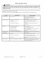
Troubleshooting table on the following pages contains
symptoms that may be seen in a malfunctioning air
conditioner. Each group of symptoms is accompanied by
one or more possible causes. Each possible cause is
accompanied by a remedy, or a test to determine if
suspect component(s) are working properly.
Table
,, Accurate leak detector, to check for refrigerant leaks.
,, Vacuum pump capable of removing all noncondensables in sealed system.
,, Charging manifold and related equipment to determine
and replenish exact refrigerant charges.
Recovery cylinder and related equipment to recover
and store refrigerant charge in sealed system.
Additional tools and equipment may be required.
6
16022061 Rev. 0
@2003
MaytagAppliancesCompany
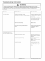
Troubleshooting
information
WARNING
To avoid risk of electrical shock, personal injury, or death, disconnect electrical power source to unit and
discharge capacitor through a 10,000 ohm resistor before attempting to service, unless test procedures require
power to be connected. Ensure all ground wires are connected before certifying unit as repaired and/or
operational.
Symptom
Possible Causes
Corrective Action
Fan motor will not operate.
No power supplied to unit.
Check fuse box/circuit
breaker for blown fuse or
tripped breaker. Replace/reset.
Check power cord for opens.
Replace cord if faulty.
Wire(s) disconnected or loose.
Ensure all connections are
tight and secure.
Fan blade will not rotate.
Fan motor capacitor faulty.
Check capacitor for open/
short. Replace if faulty.
NOTE: Discharge capacitor
before testing.
Fan motor faulty.
Check fan motor windings for
shorts/opens. Replace if
faulty.
Fan hitting shroud or blower wheel hitting scroll.
Check fan blade!blower wheel
for proper alignment on motor
shaft. Reposition if necessary.
Check fan motor for proper
position, ensure mounting
nuts/bracket tight and secure.
Fan motor operates
@2003 Maytag Appliances
intermittently.
Company
Wire(s) disconnected or loose.
Ensure all connections are
tight and secure.
Cycling on motor protector.
Replace motor.
16022061
Rev. 0
7
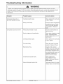
Troubleshooting
information
WARNING
To avoid risk of electrical shock, personal injury, or death, disconnect electrical power source to unit and
discharge capacitor through a 10,000 ohm resistor before attempting to service, unless test procedures require
power to be connected. Ensure all ground wires are connected before certifying unit as repaired and/or
operational.
Symptom
Possible Causes
Corrective
Action
Fan motor noisy.
Outside coil fan blade or inside
coil blower wheel loose or improperly aligned.
Check fan blade!blower wheel
for proper position. Reposition
if necessary.
Ensure hardware attaching
fan blade/blower wheel to
motor shaft is tight. Tighten if
loose, replace if stripped.
Worn fan motor bearings.
Replace motor.
Fan motor mounting hardware!bracket
loose.
Check mounting bolts/bracket
for tightness. Tighten if
necessary.
Wire(s) disconnected or loose.
Ensure all connections are
tight and secure. Correct as
required.
Compressor capacitor faulty.
Check capacitor for short.
Replace if faulty,
NOTE: Discharge capacitor
before testing.
Compressor faulty.
Check compressor motor
windings for open / shorts.
Compressor does not run,
fan motor operates normally.
Replace compressor if
faulty.
8
16022061 Rev. 0
@2003
MaytagAppliancesCompany
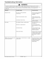
Troubleshooting
information
WARNING
To avoid risk of electrical shock, personal injury, or death, disconnect electrical power source to unit and
discharge capacitor through a 10,000 ohm resistor before attempting to service, unless test procedures require
power to be connected. Ensure all ground wires are connected before certifying unit as repaired and/or
operational.
Symptom
Possible Causes
Corrective Action
Compressor does not run,
fan motor operates normally.
Overload protector open.
Check protector for continuity.
If open, replace.
Rotary control faulty.
Ensure all control connections
are tight and secure. Check
control for proper operation
and installation. Replace if
faulty.
Wire(s) disconnected or loose.
Ensure all connections are
tight and secure.
Supply voltage out of specification.
Check input voltage for proper
levels. Take appropriate
action if voltage levels out of
specification.
Overload protector open.
Check protector for continuity.
If open, replace.
Fan motor faulty.
Check fan motor for proper
operation. Replace if faulty.
Restricted air flow.
Inspect air filter, indoor/
outdoor coil for dirt. Clean as
required. Check fins on coils
for damage. Straighten fins if
bent, attempt other repairs as
necessary. Replace coil if
repairs cannot be made.
Compressor capacitor faulty.
Check capacitor for
short. Replace if faulty.
NOTE: Discharge capacitor
before testing.
Sealed refrigerant system fault.
Test sealed system for proper
charge, leaks, and restrictions.
Compressor cycles on and off.
@2003 Maytag Appliances
Company
16022061
Rev. 0
9
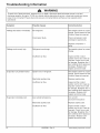
Troubleshooting
information
WARNING
To avoid risk of electrical shock, personal injury, or death, disconnect electrical power source to unit and
discharge capacitor through a 10,000 ohm resistor before attempting to service, unless test procedures require
power to be connected. Ensure all ground wires are connected before certifying unit as repaired and/or
operational.
Symptom
Possible Causes
Corrective Action
Insufficient cooling.
Low refrigerant charge.
Test sealed system for proper
charge. Ensure system is free
of leaks.
Restricted air flow.
Inspect air filter, indoor/
outdoor coil for dirt. Clean as
required. Check fins on coils
for damage. Straighten fins if
bent, attempt other repairs as
necessary. Replace coil if
repairs cannot be made.
Unit undersized for area/room.
Reduce area being cooled or
replace unit with larger
capacity model.
Outside coil fan blade or inside coil
blower wheel loose or improperly aligned.
Check fan blade!blower wheel
for proper position. Reposition
blade or bower wheel.
Excessive noise.
Ensure hardware attaching fan
blade/blower wheel to motor
shaft is tight.
10
Compressor mounting hardware loose or
grommets worn.
Check mounting bolts for
tightness. Tighten if
necessary. Don't overtighten.
Inspect grommets for wear.
Free parts, loose screws causing or allowing
excessive vibration.
Inspect unit for parts that may
have worked free, loose/
missing screws, other
)roblems that
may cause excessive
vibration.
Worn fan motor bearings.
Replace motor
16022061 Rev. 0
@2003
MaytagAppliancesCompany
Troubleshooting
information
WARNING
To avoid risk of electrical shock, personal injury, or death, disconnect electrical power source to unit and
discharge capacitor through a 10,000 ohm resistor before attempting to service, unless test procedures require
power to be connected. Ensure all ground wires are connected before certifying unit as repaired and/or
operational.
Symptom
Possible Causes
Corrective Action
Excessive noise.
Fan motor mounting hardware!
bracket loose.
Check mounting bolts/bracket
for tightness. Tighten if
necessary.
Copper tubing improperly routed.
Inspect copper tubing for
excessive vibration. Secure
tubing.
Compressor internal noise.
Inspect compressor for proper
operation. Replace.
No refrigerant charge in sealed system.
Test sealed system for leak.
Recharge unit.
Restriction in sealed system.
Evacuate sealed system.
Remove restriction, recharge
unit.
Compressor faulty.
Check compressor motor
windings for open / shorts.
Replace compressor.
Rotary Control faulty.
Ensure all control connections
No cooling.
are tight and secure. Check
control for proper operation
and installation. Replace if
faulty.
Wattage slowly decreases below
minimum specification.
@2003
MaytagAppliancesCompany
Undercharged, restricted strainer or plugged
capillary tube.
16022061
Rev. 0
Test sealed system for proper
charge. Ensure system is free
of leaks/restriction. Repair
Evacuate & recharge
sealed system.
11
Troubleshooting
information
WARNING
To avoid risk of electrical shock, personal injury, or death, disconnect electrical power source to unit and
discharge capacitor through a 10,000 ohm resistor before attempting to service, unless test procedures require
power to be connected. Ensure all ground wires are connected before certifying unit as repaired and/or
operational.
Symptom
Possible Causes
Corrective Action
Wattage decreases immediately.
No refrigerant.
Test sealed system for proper
charge. Ensure system is free
of leaks. Repair as required.
Compressor faulty.
Check compressor motor
windings for open/shorts.
Replace compressor if
faulty.
Wattage continuously high.
Evaporator coil partially frosted.
Evaporator completely iced.
12
Refrigerant overcharge.
Test sealed system for proper
charge.
Insufficient air flow.
Inspect air filter, indoor!
outdoor coil for dirt. Clean as
required. Check fins on coils
for damage. Straighten fins if
bent, attempt other repairs as
necessary. Replace coil if
repairs cannot be made.
System low on refrigerant.
Test sealed system for proper
charge. Ensure system is free
of leaks. Repair as required.
Restricted capillary tube.
Replace capillary tube.
Insufficient air flow.
Inspect air filter, indoor/
outdoor coil for dirt. Clean as
required. Check fins on coils
for damage. Straighten fins if
bent, attempt other repairs as
necessary. Replace coil if
repairs cannot be made.
Low outside temperature.
Turn unit off.
(Consumer education)
Restricted capillary tube.
Replace capillary tube.
Insufficient air flow.
Inspect air filter, indoor/
outdoor coil for dirt. Clean as
required. Check fins on coils
for damage. Straighten fins if
bent, attempt other repairs as
necessary. Replace coil if
repairs cannot be made.
16022061 Rev. 0
@2003
MaytagAppliancesCompany
Testing Procedures
WARNING
To avoid risk of electrical shock, personal injury, or death, disconnect electrical power source to unit and
discharge capacitor through a 10,000 ohm resistor before attempting to service, unless test procedures require
power to be connected. Ensure all ground wires are connected before certifying unit as repaired and/or
operational.
Low Voltage
Testing Capacitors
Low voltage can result in one or more of the following
problems:
Compressors in these units use permanent split
capacitor type motors, eliminating need for start
capacitors and relays. A low capacitance
"compressor run capacitor" assists during start, and
remains in system during operation. See directions
on capacitor, and wiring diagram (on Technical
Sheet) for unit under test.
Capacitors are also used on permanent split
capacitor (PSC) fan motors.
To test capacitors:
Unit will not operate.
Compressor motor cycling.
Premature failure of overload protector.
Frequent blown fuses or tripped circuit breakers.
Premature failure of compressor or fan motor.
Noticeable dimming of lights when unit is operating.
Common causes for low voltage include inadequate
supply circuit wiring; use of extension cords; and
loose fuses or connections in fuse box, circuit
breaker, or distribution panel.
NOTE: A good indication of voltage problems caused
by inadequate or faulty wiring is voltage
levels that do not remain constant under load
(supply voltage fluctuates).
A less common cause for low voltage is voltage from
local electric utility is low (sometimes called "brown
outs"). If this is the case, have consumer contact
local electric utility for assistance.
All units should operate normally if power stays within
specifications (refer to Technical Sheet for unit under
test). Test for low voltage using voltmeter. Verify
voltage level at circuit breaker/distribution panel for
unit under test, and at electrical outlet serving unit.
Take initial voltage readings with air conditioner
turned off. Take additional readings during start-up of
unit, and again while unit is operating. All readings
should be within specifications and remain constant.
NOTE: Supply voltage may drop momentarily during
initial start-up and when compressor first
starts, but should always remain within
specifications.
1. Disconnect power to unit.
2. Discharge capacitor by shorting capacitor
terminals through a 10,000 ohm resistor.
Disconnect leads attached to capacitor terminals.
3. Set ohmmeter on highest scale. Attach ohmmeter
leads to capacitor and observe ohmmeter display:
•Good condition--indicator
swings to zero and
slowly returns toward infinity.
•Shorted--indicator
swings to zero and remains.
•Open--indicator does not move.
4. Reverse ohmmeter leads on capacitor and repeat
step 3.
Checking
Overload
Protectors
Overload protectors protect compressor from current
and temperature overloads by removing power from
compressor before it is damaged.
To check overload protector:
1. Disconnect power to unit.
2. Remove overload lead from compressor terminal.
3. Use ohmmeter to test continuity between overload
terminals. If open, replace overload.
Checking
Compressor
Windings
High Voltage
Resistance Test
1. Disconnect power to unit.
2. Remove leads from compressor terminals.
3. Set ohmmeter to lowest scale.
4. Attach ohmmeter to compressor terminals C and
S. Note reading.
5. Attach ohmmeter to compressor terminals C and
R. Note reading. If either compressor winding
reads open (infinite or very high resistance) or
dead short (0 ohms), replace compressor.
16022061 Rev. 0
High voltage causes motors to overheat, cycle on
their protectors, or break down electrically. This
problem can only be solved by local electric utility.
@2003 Maytag Appliances
Company
13
Testing Procedures
WARNING
To avoid risk of electrical shock, personal injury, or death, disconnect electrical power source to unit and
discharge capacitor through a 10,000 ohm resistor before attempting to service, unless test procedures
require power to be connected. Ensure all ground wires are connected before certifying unit as repaired
and/or operational.
NOTE: Motor windings typically have very little
resistance. When checking windings for
shorts, ensure ohmmeter is set on lowest
scale. Good windings may indicate as little
as 2 ohms of resistance.
Ground
Test
1. Disconnect power to unit.
2. Remove leads from compressor terminals.
3. Set ohmmeter to highest scale.
4. Attach one lead of ohmmeter to body of
compressor. Ensure connection point is clean,
and makes good contact with compressor.
5. Attach remaining lead on ohmmeter to C, then S,
then R terminals on compressor. If ohmmeter
indicates continuity between compressor case
and any terminal, replace compressor.
Compressor
Burnout
To avoid personal injury, do not allow sludge or oil
from compressor to contact skin. Severe burns may
result.
NOTE: Before opening any refrigeration system, EPA
regulations require refrigerant in system to be
captured for safe disposal.
NOTE: Do not use captured or recycled refrigerant in
Amana units. Captured or recycled refrigerant
voids all Amana and/or compressor manufacturer's
warranties.
When a compressor burns out, high temperature
causes the refrigerant, oil, and motor insulation to
decompose, forming acids and sludge.
If a compressor is suspected of burning out:
1. Replace Compressor.
4. Check for continuity between each motor lead with
ohmmeter.
5. Check for ground by attaching one lead of
ohmmeter to motor frame (ground). Attach
remaining ohmmeter lead to each fan motor lead,
one at a time.
NOTE: Ensure contact point between ohmmeter lead
and motor frame is clean.
Replace fan motor if windings test open (very high or
infinite resistance), or if any continuity is indicated
between motor frame and windings.
Leak Testing
I
&
DANGER
To preventseriousinjury
ordeath from violent
explosions, NEVER use oxygen or acetylene for
pressure testing or cleanout of refrigeration
systems. Free oxygen will explode on contact with
oil. Acetylene will explode spontaneously when put
under pressure.
It is important to check sealed system for refrigerant
leaks. Undetected leaks can lead to repeated service
calls and eventually result in system contamination,
restrictions, and premature compressor failure.
Refrigerant leaks are best detected with electronic
leak detectors.
Testing Systems Containing a Refrigerant Charge
1. Stop the operation (turn air conditioner off).
2. Holding leak detector exploring tube as close to
system tubing as possible, check all piping, joints,
and fittings.
NOTE: Use soap suds on areas leak detector cannot
reach or reliably test.
Fan Motor
1. Disconnect power to unit.
2. Discharge capacitor by shorting capacitor
terminals through a 10,000 ohm resistor.
3. Disconnect fan motor leads from selector switch
and respective capacitor.
14
Testing Systems Containing No Refrigerant
Charge
1. Connect cylinder of nitrogen, through gauge
manifold, to process tube of compressor and
liquid line strainer.
2. Open valves on nitrogen cylinder and gage
manifold. Allow pressure to build within sealed
system.
16022061 Rev. 0
@2003
MaytagAppliancesCompany
Testing Procedures
WARNING
To avoid risk of electrical shock, personal injury, or death, disconnect electrical power source to unit and
discharge capacitor through a 10,000 ohm resistor before attempting to service, unless test procedures require
power to be connected. Ensure all ground wires are connected before certifying unit as repaired and/or
operational.
3. Check for leaks using soap suds.
If a leak is detected in a joint, do not to attempt to
repair by applying additional brazing material. Joint
must be disassembled, cleaned and rebrazed.
Capture refrigerant charge (if system is charged),
unbraze joint, clean all parts, then rebraze. If leak is
detected in tubing, replace tubing. If leak is detected
in either coil, replace coil.
•If temperature of condenser tubing drops at any
point, tubing is restricted at point of temperature
drop (if restriction is severe, frost may form at point
of restriction and extend down in direction of
refrigerant flow in system). Go to step 4.
3. Turn unit off and time how long it takes high and
low pressure gauges to equalize:
•If pressure equalization takes longer than 7
minutes, a restriction exists in the capillary tube/
strainer. Go to step 4.
[
CAUTION
]
To reduce risk of personal injury or property
damage, take necessary precautions against
high temperatures required for brazing.
4. Recover refrigerant in sealed system.
Satisfactory results require cleanliness, experience,
and use of proper materials and equipment.
Connections to be brazed must be properly sized
and cleaned.
Generally accepted brazing materials are:
-Copper to copper joints: SIL-FOS (alloy of 15
percent silver, 80 percent copper, and 5 percent
phosphorous). Use without flux. Recommended
brazing temperature
is approximately
1400°F.
DO NOT USE FOR COPPER TO STEEL
CONNECTION.
•Copper to steel joints: SILVER SOLDER (alloy of
30 percent silver, 38 percent copper, 32 percent
zinc). Use with fluoride based flux. Recommended
brazing temperature is approximately 1200°F.
Restriction
NOTE: Before opening any refrigeration system,
capture refrigerant in system for safe
disposal.
5. Remove power from unit.
CAUTION
1
To reduce risk of personal injury or property
damage, take necessary precautions against
high temperatures required for brazing.
6. Remove and replace restricted device.
7. Evacuate sealed system.
8. Charge system to specification.
NOTE: Do not use captured or recycled refrigerant in
units. Captured or recycled refrigerant voids
all and!or compressor manufacturer's
warranties.
Testing
Restrictions in sealed system generally occur in
capillary tube, but can exist anywhere in the system.
To determine if a restriction exists:
1. Attach gauge and manifold between suction and
discharge sides of sealed system.
2. Turn unit on, and allow pressure on each side to
stabilize. Inspect condenser side of system. Tubing
on condenser should be warm and temperature
should be equal throughout (no sudden drops at any
point along tubing):
•If temperature of condenser tubing is consistent
throughout, go to step 3.
@2003
•If pressure equalization takes less than 7 minutes,
system is not restricted. Check for other possible
causes of malfunction.
MaytagAppliancesCompany
16022061
Evacuation
l
CAUTION
J
To avoid risk of fire, sealed refrigeration system
must be air free. To reduce risk of air
contamination follow evacuation procedures
exactly.
Rev. 0
15
Testing Procedures
WARNING
To avoid risk of electrical shock, personal injury, or death, disconnect electrical power source to unit and
discharge capacitor through a 10,000 ohm resistor before attempting to service, unless test procedures
require power to be connected. Ensure all ground wires are connected before certifying unit as repaired
and/or operational.
NOTE: Before opening any refrigeration system, EPA
regulations require refrigerant in system to
be captured for safe disposal.
Proper evacuation of sealed refrigeration system is
an important service procedure. Usable life and
operational efficiency of air conditioner greatly
depends upon how completely air, moisture and
other non-condensables are evacuated from sealed
system.
Air in sealed system causes high condensing
temperature and pressure, resulting in increased
power requirements and reduced performance.
Moisture in sealed system chemically reacts with
refrigerant and oil to form corrosive hydrofluoric and
hydrochloric acids. These acids attack motor
windings and parts, causing Restriction / Burnout
condition.
Equipment required to evacuate sealed system
includes:
,, High vacuum pump, capable of producing a
vacuum equivalent to 25 microns.
,, Thermocouple vacuum gauge capable of providing
true readings of vacuum in system.
l
CAUTION
J
To avoid damage to compressor motor, never
use air conditioner compressor as a vacuum
pump or run compressor when system is under
high vacuum.
To evacuate sealed refrigeration system:
1. Connect vacuum pump, vacuum tight manifold set
with high vacuum hoses, thermocouple vacuum
gauge and charging cylinder as shown in
illustration.
2. Connect low side line to compressor process tube.
3. Connect high side line to process tube of liquid line
strainer.
NOTE: If a compression or flare fitting cannot be
attached to process tube(s) and still leave
room for a pinch-off, swage tube(s) and
braze on an additional length of tubing.
16
4. Start vacuum pump and open shut off valve to high
vacuum gauge manifold only.
5. After compound gauge (low side) drops to
approximately 29 inches gauge, open valve to
vacuum thermocouple gauge.
6. Ensure vacuum pump will blank-off to a maximum
of 25 microns.
NOTE: A high vacuum pump can only produce a
good vacuum if oil in pump is not
contaminated.
7. If vacuum pump is working properly, close valve to
vacuum thermocouple gauge.
8. Open high and low side valves of high vacuum
manifold set. With valve on charging cylinder
closed, open manifold valve to cylinder.
9. Evacuate system to at least 29 inches gauge.
Open valve to thermocouple vacuum gauge.
10.Continue to evacuate to a maximum of 250
microns. Close valve to vacuum pump and watch
rate of rise:
•If vacuum does not rise above 1500 microns in
three minutes, system can be considered properly
evacuated.
•If thermocouple vacuum gauge continues to rise,
then levels off above 5000 microns, moisture and
non-condensables are still present. Re-evacuate.
•If gauge continues to rise above 5000 microns, a
leak is present. Locate, repair, and re-evacuate.
11. When system is properly evacuated, close valve
to thermocouple vacuum gauge and vacuum
pump. Shut off pump and prepare to charge
system.
Charging
NOTE: Do not use captured or recycled refrigerant in
units. Captured or recycled refrigerant
voids all and/or compressor manufacturer's
warranties.
NOTE: Charge system with exact amount of
refrigerant. SeeTechnical Sheet or refer to
unit nameplate for correct refrigerant charge.
Inaccurately charged system will cause
future problems.
16022061 Rev. 0
@2003
MaytagAppliancesCompany
Testing Procedures
WARNING
To avoid risk of electrical shock, personal injury, or death, disconnect electrical power source to unit and
discharge capacitor through a 10,000 ohm resistor before attempting to service, unless test procedures require
power to be connected. Ensure all ground wires are connected before certifying unit as repaired and/or
operational.
To charge system:
NOTE: When using ambient compensated calibrated
charging cylinder, allow liquid refrigerant to
enter high side only.
1. With no power applied to unit, allow liquid
refrigerant to flow into system until no more
refrigerant can be added.
2. Close valve on high side of manifold.
3. Start (apply power to) system and charge to
specification through low side. Do not charge
through low side in a liquid form.
4. Close low side valve on manifold and pinch-off
both process tubes. Remove manifold set, crimp
shut open ends of process tubes and braze.
5. Recheck for refrigerant leaks.
Refrigerant
Precautions
To avoid personal injury, do not allow refrigerant to
contact eyes or skin.
To avoid risk of property damage, do not use
refrigerant other than that shown on unit serial
number identification plate.
NOTE: All precautionary measures recommended
refrigerant manufacturers and suppliers
apply and must be observed.
Using
Line Piercing
by
Valves
Line piercing valves can be used for diagnosis, but
are not suitable for evacuating or charging due to
holes pierced in tubing by valves.
NOTE: Do not leave line piercing valves on system.
Connection between valve and tubing is not
hermetically sealed. Leaks will occur.
Open Lines
During any processing of refrigeration system, never
leave lines open to atmosphere. Open lines allow
water vapor to enter system, making proper
evacuation more difficult.
@2003
MaytagAppliancesCompany
16022061
Rev. 0
17
Disassembly
Procedures
[
]
WARNING
To avoid risk of electrical shock, personal injury, or death, disconnect electrical power source to unit and
discharge capacitor through a 10,000 ohm resistor before attempting to service, unless test procedures
require power to be connected. Ensure all ground wires are connected before certifying unit as repaired
and/or operational.
The following paragraphs describe how to
disassemble the unit. Disassembly to some extent is
required to install unit, to perform troubleshooting
procedures, and to remove and replace faulty
corn ponents.
Component names used throughout disassembly
procedures are the same as those used in Parts
Manuals.
For quicker reassembly, disassemble unit under test
only to extent necessary to troubleshoot and repair.
Unless noted, reassembly is opposite of disassembly.
[
WARNING
To avoid risk of personal injury or death due to
electrical shock, ground wires and wires colored
like ground wires are NO'[" to be used as current
carrying conductors. The standard accepted
color coding for ground wires is green or green
with a yellow stripe. Electrical components
such as the compressor and fan motor are
grounded through an individual wire attached to
the electrical component and to another part of
the air conditioner. Ground wires should not be
removed from individual components while
servicing, unless the component is to be
removed and replaced. It is extremely important
to replace all removed ground wires before
completing service.
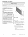
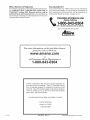
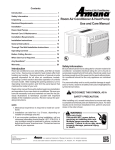
Swing filter cover to the
left to expose filter
Press two buttons
to release cover.
Air Filter Removal
To remove air filter:
1. Press two buttons on front air filter cover to
release tabs.
2. Swing air filter cover open to expose filter, then
pull filter out and away from front frame.
NOTE: If air filter is dirty, clean with vacuum, or
hand wash. Ensure filter is completely dry
before reinstalling in unit
Grill
Front (Insert)
Removal
1. Remove Front Frame ( see Front Frame
Removal).
2. Press two buttons on front air filter cover to
release tabs.
3. On back side of the hinged insert press bottom
hinge out to release top hinge from Front Frame.
18
16022061
Rev. 0
@2003
MaytagAppliancesCompany
Disassembly
Procedures
[
WARNING
To avoid risk of electrical shock, personal injury, or death, disconnect electrical power source to unit and
discharge capacitor through a 10,000 ohm resistor before attempting to service, unless test procedures
require power to be connected. Ensure all ground wires are connected before certifying unit as repaired
and/or operational.
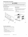
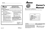
Front Frame Removal
Chassis
Removal
To remove front frame:
To remove Chassis:
1. Remove 2 screws securing front frame to air
conditioner chassis.
1. Remove Front Frame (See Front Frame Removal)
2. Remove one screw securing clip to case from
chassis. Remove one screw in back of unit
holding
2. Remove screw from behind air filter cover.
3. Pull front frame out and away from air conditioner.
case to chassis.
3. Remove chassis by sliding out of outer case.
Screws
Screw
Clips
Screw
Front Frame Clips Removal
1. Remove Front Frame (see Front Frame Removal).
2. Press two buttons on front air filter cover to release
tabs.
3. Swing Air Filter Cover open to expose back side of
Air Filter Cover.
4. On back side of Front Frame push Insert Grill Front
Clips through Front Frame.
5. To reinstall Air Filter Clips push clips into openings
in the front side of the Front Frame.
@2003
MaytagAppliancesCompany
16022061
Rev. 0
19
Disassembly
Procedures
[
WARNING
]
To avoid risk of electrical shock, personal injury, or death, disconnect electrical power source to unit and
discharge capacitor through a 10,000 ohm resistor before attempting to service, unless test procedures
require power to be connected. Ensure all ground wires are connected before certifying unit as repaired
and/or operational.
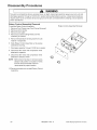
Rotary
Control
Assembly
Removal
Rotary Control Assembly Removal
To remove Rotary Control Assembly:
1. Remove Front Frame (see Front Frame Removal)
2. Remove control knobs.
3. Remove cover plate
4. Remove 2 screws holding Rotary Control
Assembly to chassis.
5. Remove temperature sensing bulb from bulb
retainer in evaporator.
6. Slide Rotary Control Assembly out to expose
switches and wiring.
7. Discharge capacitor through 10,000 ohm resistor.
8. Disconnect fan motor and compressor wires
attached to capacitor.
9. Disconnect fan motor and compressor wires
attached to selector switch.
NOTE: Before disconnecting or removing wires,
always note position or location of wires.
Ensure all disconnected wires are
reconnected to proper location.
10. Reverse procedure to reinstall Rotary Control
Assembly.
20
16022061
Rev. 0
@2003
MaytagAppliancesCompany
Disassembly
Procedures
[
A
WARNING
To avoid risk of electrical shock, personal injury, or death, disconnect electrical power source to unit and
discharge capacitor through a 10,000 ohm resistor before attempting to service, unless test procedures
require power to be connected. Ensure all ground wires are connected before certifying unit as repaired
and/or operational.
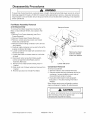
Fan Motor Assembly
and Disassembly
Removal
Remove
To remove Fan MotorAssembly (including Fan
Motor, (indoor) Blower Wheel, and (outdoor) Fan
Blade):
1. Remove Front Frame Assembly (see Front
Frame Removal).
2. Remove Chassis (see Chassis Removal).
3. Remove screws securing covers over blower
wheel and condenser fan.
4. Remove screws holding condensor coil to shroud
and chassis.
5. Carefully rotate condenser coil up and to the left to
expose condenser fan blade.
6. Loosen condenser fan blade with screwdriver and
remove fan blade.
7. Loosen set screw on blower wheel so it will slide
off shaft.
8. Disconnect motor wiring from Rotary switch
control compartment (See Rotary Control
Assembly Removal)
9. Remove 4 hex head screws holding motor in
bracket.
10. Slide motor out of blower wheel and remove from
bracket.
11. Reverse procedure to reinstall Fan Motor.
Covers
Loosen Set Screw
Remove hex head
screws to release
motor from bracket
Loosen Set Screw
Condenser
Removal
To remove condenser:
1. Remove chassis ( see Chassis Removal).
2. Remove screws securing condenser shroud to
condenser ( screws located on each side of
shroud)Shroud remains in place.
3. Evacuate sealed system (see paragraph
Evacuation, in Trouble shooting Information
section).
Note: Before opening any refrigeration system,
capture refrigerant in system for safe disposal.
I
CAUTION
I
To reduce risk of personal injury or property damage
take necessay precautions against high
temperatures required for brazing
@2003 Maytag Appliances
Company
16022061
Rev. 0
21
Disassembly
Procedures
[
]
,Ek WARNING
To avoid risk of electrical shock, personal injury, or death, disconnect electrical power source to unit and
discharge capacitor through a 10,000 ohm resistor before attempting to service, unless test procedures
require power to be connected. Ensure all ground wires are connected before certifying unit as repaired
and/or operational.
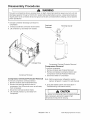
4. Unbraze condenser discharge connection to
compressor.
5. Unbraze condenser connection shown below.
Overload
Terminal
Cover
6. Lift condenser up and away from chassis.
Protecto
/
Unbraze Here
Compressor Overload Protector Removal
Compressor
Condenser Removal
Compressor
Overload
Protector
Removal
To remove compressor:
1. Remove chassis (see Chassis Removal).
2. Remove compressor overload protector (see
Compressor Overload Protector Removal).
3. Disconnect leads on compressor.
Removal
To remove compressor overload protector:
1. Remove chassis (see Chassis Removal).
2. Remove nut securing terminal cover to
compressor, then lift terminal cover up and away
from compressor.
3. Disconnect overload protector leads.
4. Lift overload protector up and away from
compressor.
Note: Before opening any refrigeration system,
capture refrigerant in system for safe disposal.
4. Evacuate sealed system (see Evacuation in
Troubleshooting Information section).
[
CAU'nON
J
To reduce risk of personal injury or property damage,
take nescessary precautions against high
J temperatures required for brazing
22
16022061
Rev. 0
@2003
MaytagAppliancesCompany
Disassembly
Procedures
[
WARNING
To avoid risk of electrical shock, personal injury, or death, disconnect electrical power source to unit and
discharge capacitor through a 10,000 ohm resistor before attempting to service, unless test procedures
require power to be connected. Ensure all ground wires are connected before certifying unit as repaired
and/or operational.
5. Unbraze compressor discharge tube
connection to condenser coil.
6. Unbraze compressor suction tube connection
to evaporator.
7. Remove nuts securing compressor to base
pan.
To reduce risk of personal injury or property
damage, take necessary precautions against
high temperatures required for brazing.
8. Lift compressor up and away from chassis.
4. Unbraze Evaporator Suction connection to
corn presson
Unbraze Here
5. Unbraze Evaporator connection to capillary tube.
6. Remove 4 screws holding Evaporator to housing.
7. Lift Evaporator out and away at top from chassis.
Unbraze Here
Evaporator
Removal
To remove Evaporator:
1. Remove Front Frame assembly (see Front
Frame assembly removal).
2. Remove Chassis (see Chassis Removal).
NOTE: Before opening any refrigeration system,
capture refrigerant in system for safe
disposal.
3. Evacuate sealed system (see paragraph
Evacuation, in Troubleshooting Information
section).
@2003 Maytag Appliances
Company
16022061
Rev. 0
23
[]
@2003
MaytagAppliancesCompany
16022061
Rev. 0
A-1
BUILT BETTER THAN IT HAS TO BE'"
Owner's
Ma.ual
Room
Air
Keep
for future
manual
Conditioner
reference.
Be sure
manual
stays
with
air conditioner.
Contents
I. Description ...................................................
II. Unpacking ....................................................
Ill. Electrical Requirements ..............................
IV. Installation ....................................................
V. Normal Care and Maintenance ..................
Vl. General Operating instructions ................
Vii. Controls ......................................................
Before Calling For Service ................................
When Service is Required ................................
Any Questions? .................................................
I. Description
This room air conditioner cools, dehumidifies and filters the
air inside your home.
Sections I through Vl of this manual provide general operating instructions, installation instructions, and maintenance
instructions for your room air conditioner. These general
instructions apply to all models. Section VII provides control
operation information for each model. After reading Sections I through Vl, turn to Section VII and find the control
layout that matches your specific room air conditioner model.
Read the information on this page carefully.
A - 2
16022061
A-2
A-3
A-3
A-4
A-15
A-16
A-16
A-17
A-18
A-19
important:
It is important, both for your personal
safety and to avoid possible damage to your appliance
or your home, that you observe the safety instructions
that are given following this symbol.
Rev. 0
A
RECOGNIZE
AS A SAFETY
@2003
THIS SYMBOL
PRECAUTION
MaytagAppliancesCompany
--
_k
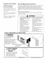
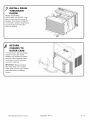
III. Electrical
WARNING
HiGH TEMPERATURE
STRESS
HAZARD
This room air conditioner
is not meant to
provide unattended
cooling or life support
for persons or animals that are unable to
react to failure of the product.
The failure of an unattended air conditioner
may result in extreme heat in the conditioned
space causing overheating
or death of
persons or animals.
Precautions must be taken to ward off or
guard against such an occurrence.
Requirements
ELECTRICAL GROUNDING INSTRUCTIONS
This appliance is equipped with a three-prong grounding
plug for protection against possible shock hazards Ifa twoprong wall receptacle is encountered, the customer is required to contact a qualified electrician and have the twoprong wall receptacle replaced with a properly grounded
three-prong wall receptacle in accordance with the National
Electrical Code.
Room air conditioners are designed to operate according to
requirements on the nameplate and as shown in Table 1
Fuse or circuit breaker ratings must be according to the fuse
instruction label and as shown in Table 1 and the label on the
electrical cord Do not plug models marked
"Use on Single Outlet Circuit Only"
into a circuit with another appliance or light fixture.
II. Unpacking
When unpacking visually inspect the unit. Report any
damage to the delivering carrier immediately. Remove and
discard all packing material. On some models the air
conditioner front and/or mounting kit hardware may be
packed separately.
Record the model, serial and manufacturing numbers of
your unit in the space provided below. This information is
found on a nameplate visible on the right hand side of the air
conditioner outer case. The rated voltage, amperage and
capacity for your specific model can also be found on this
nameplate. Read the warranty provided on the last page of
this manual. Keep this manual and a copy of your sales
receipt for future reference. You may also want to record in
the space provided the date purchased and the selling
dealer.
OWNER'S
PRODUCT
MODEL
NUMBER
SERIAL
NUMBER
IDENTIFICATION
_k
WARNING
To avoid death, personal injury or property
damage due to electrical
shock, this unit
must
be grounded.
Do not under any
circumstances
cut or remove the round
grounding
prong from the plug. Do not use
a two-prong
adapter.
WARNING
To avoid death, personal injury or property
damage due to electrical shock, do not use
an extension cord. Do not pinch the power
cord. Do not remove the warning tag from
the power cord.
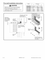
Circuit Rating
MANUFACTURING
NUMBER
Unit Plug Type
Owner's Name
(_
Receptacle
required
Breaker or
Time
Delay Fuse
_
NEMA No 5-15F
125V-15AMP
Voltage Rating
On Unit Nameplate
115V
NEMA No 5-15R
Address
City
State
/
(_
Zip
/
_
NEMA No. 6-15F
250V-15AMP
230/208V
at 12
amperes rated
or less
250V-20AMP
12 230/208V
amperes but
mor_
ratednotover
than 16 amperes
250V-30AMP
230/208V
at 24
amperes rated
or less
NEMA No. 6-15R
Date of Purchase
{_
Authorized
_
kIEMA No 6-20F
NEMA No. 6-20R
NEMA No. 6-30F
NEMA No 6-30R
Dealer
Address
_
City
(
State
Zip
/
Phone Number
@2003
Table 1
MaytagAppliancesCompany
16022061
Rev. 0
A-3
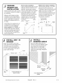
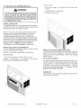
Installation
Requirements
nstaH
Consider
Description
Location
For proper air conditioner operation all vents, indoor and out, must be free of
obstructions.
Carefully survey installation location. Indoor obstructions could include, but are
not limited to, furniture, curtains, or plants. Outdoor obstructions could include,
but are not limited to, landscaping plants and materials, structural design, or
pathways.
Use window frame dimensions shown in this manual for easy installation.
Instant Mount Kit, supplied with unit, is designed for mounting in most doublehung windows without storm windows.
To accommodate unit in window frame with storm window, modify sill by adding
wood strips to inner and outer sills. This raises the unit and eliminates
interference of storm window frame.
Electrical Requirements
A separate (dedicated) circuit is required for units labeled "Use
on
Single Outlet Circuit Only."
DO NOT use an extension cord. If air conditioner power supply cord does not
reach intended wall outlet, have a qualified electrician install (or move) an
appropriate receptacle closer to unit.
DO NOT use an adapter plug. If plug on air conditioner does not match intended
outlet, have a qualified electrician replace outlet with correct type.
For more specific electrical information, see the power cord requirements section
in this manual.
Special Considerations
A - 4
Air conditioner weighs between 80 and 150 pounds (depending on model). Have
additional help for lifting and carrying.
16022061
Rev. 0
@2003
MaytagAppliancesCompany
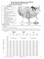
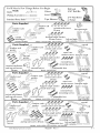
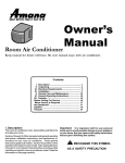
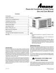
Do you have the right size air conditioner
for the room you want to cool?
Check the guide below and see.
InstructioRs
Measure the room to be cooled in
square feet.
Select the region (1,2, or 3) that
best fits your location from the
map.
Using the chart corresponding to
your region, find the column
marked (Size of Area to be Cooled
in square feet).
Reading down the column, select a
number that most closely matches
your room size.
Follow this row across to the
column that describes the air
conditioner exposure direction, and
room characteristics.
The number you select will be the
1.
2.
3.
4.
5.
6.
Rochester
New
Haven
Tucson
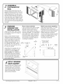
1
2
3
coo,aPpr°x'ma*e
noe0ed*Oyour
room.
b*u
s,ze
Additional
I11111111
conditions:
Region
Region 2
Region 3
,, If average occupancy of area is more than two people, add 600 Btu/hour per person. If average is one person, subtract
600 Btu/hour.
.
Add 1200 Btu/hour if area includes a kitchen.
,, If room is heavily shaded, subtract 10 percent from capacity. Increase capacity by 10 percent if area is very sunny.
Note: For best results, select a room air conditioner with cooling capacity (Btu/hour rating) closest to, but not exceeding,
estimated size.
NORTH OR
EAST OR
WEST
SHADED
SOUTH
8o
_•
z _=_
_ _
z _=_
8o
_ •
z _=_
a to
_e
Cc 3led
Required Air Conditioner Cooling
Capacity Btu/hour
Required Air Conditioner Cooting
Capacity Btu/hour
Required Air Conditioner Cooting
Capacity Btu/hour
in
_/L
sq
lar_
f_ et
G
O0
3,600
4,000
5.200
5,500
5,900
7,000
61600
7,000
81100
50
4,000
4,400
51900
6,000
6,400
7,800
71100
7,500
81900
oo
50
_,300
3,200
_,900
3,500
_1600
4,400
_,400
5,100
_,900
5,400
_,600
6,200
_1500
6.200
_,000
6,500
50
4,700
5.300
7,400
6,800
7,400
9,400
7.900
8,500
10,600
z 50
5,500
6.200
8.900
7,600
8,400
11.100
8.700
9,500
12,200
*00
_,800
d600
_1600
_,000
_,900
111900
51100
10,000
13,000
50
6,200
71100
10,400
8,400
9,400
121700
91500
10,500
13,800
00
6,600
7.600
11,100
8,900
9,900
13.500
10,000
11,000
14,600
50
_,900
_000
11,600
_,300
10.400
14.300
_00
7,300
8}400
12,600
9,700
101900
151100
10,400
10,800
11,500
12,000
15,400
16,200
} 50
7,700
8.900
13,400
10,100
11.400
15.900
11,200
12,500
17,000
8,000
91400
14,100
10,600
111900
161700
11,700
13,000
17,800
8,300
9.800
14,900
11,000
12.400
17,500
12,100
13,500
16,600
,oo
|
_
_1_
_00
50
'1
_ 00
_,100 _:600 _200
_1800
7.300
_,200 _,900 lO.300 _:300 _,000 11,400
8,700
10,200
15,600
11,400
121900
18.300
12,500
14,000
19,400
9,100
10,700
16,300
11,800
13.400
19.100
12,900
14,500
20,200
9,400 11,100 17,10012,300 14:000 19:90013,400 15,100 21,000
_!00_
@2003
00
10.100
12,000
18,500
13,100
14.900
21.400
14,200
16,000
22,600
i0_
101900
12,900
20,000
13,900
151900
231000
15,000
17,000
24,200
!0_
111600
13,800
21,500
14,700
16.900
241700
15,800
18,000
25,800
12.300
14,700
23,000
15,600
17.900
26.300
16,700
19,100
27,400
MaytagAppliancesCompany
16022061
Rev. 0
A -5
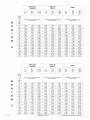
NORTH OR
SHADED
_> o
Size of
Area to
be
Cooled
(in
R
square
feet)
150
200
O
=_
Required Air Conditioner Cooling
Capacity Btu/hour
E>e
9==
___._=
Required Air Conditioner Cooling
Capacity Btu/hour
3,900
5,000
4,100
4,500
4,500
5,000
5,900
6,700
6,800
6,700
7,300
300
35O
4,900
5,500
7,600
7,300
7,900
5,300
6,000
8,500
8,500
10,900
4OO
450
5,800
6,200
6,600
7,100
9,400
10,200
7,800
8,300
8,700
9,100
9,600
11,900
12,800
500
6,600
7,600
7,000
8,100
11,100
12,000
9,200
9,700
10,200
10,800
13,700
550
6OO
65O
700
7,500
7,900
8,700
9,200
12,900
10,200
11,400
13,700
10,700
8,300
8,800
9,200
9,700
10,300
14,600
75O
11,200
11,700
800
65O
2
g-_
WEST
3,600
250
|
9.-=
EAST OR
SOUTH
9,600
5,800
6,300
6,100
_
_
=_
g-
9==
Required Air Conditioner Cooling
Capacity Btu/hour
7,100
8,100
7,100
7,600
7,400
8,000
8,400
9,400
9,000
8,100
8,600
10,300
I0,000
8,600
9,200
11,300
9,100
9,600
9,800
10,400
12,200
lO,OgO
10,900
10,500
11,000
11,500
12,100
15,000
11,500
12,700
12,000
15,600
16,600
12,000
13,800
16,900
17,900
12,600
17,500
18,500
19,400
12,500
13,000
13,900
14,500
12,200
13,200
13,800
13,500
15,100
14,000
14,500
15,700
16,300
21,600
14,700
13,200
14,100
16,000
18,800
10,800
15,500
16,400
19,800
20,700
11,300
11,800
17,300
18,100
12,700
13,200
14,400
15,000
20,300
15,000
16,900
15,500
17,500
23,500
24,500
900
10,000
950
1000
10,500
10,900
12,400
19,000
13,700
15,600
12,900
19,900
14,200
16,200
22,200
23,200
1100
11,700
13,900
21,600
15,100
17,300
25,000
16,40g
18,600
26,300
1200
12,600
13,400
15,000
16,000
23,400
25,100
16,100
17,100
18,500
19,700
26,900
28,800
17,400
18,400
19,800
21,000
28,200
30,100
14,300
17,100
26,900
16,100
20,900
30,700
19,400
22,200
32,000
1300
1400
NORTH OR
SHADED
b
o>
*_ .....
=
21,300
EAST OR
SOUTH
_*_1=-
_
22,600
WEST
___ _
oEo
>_
-*_Z
_-_
rY<
Size of
Area to
be
Cooled
(in
square
feet)
150
6,500
6,800
8,000
8,000
8,300
9,500
7,500
8,200
9,100
10,200
8,600
9,000
10,600
5,600
7,100
7,600
9,100
9,700
11,700
6,200
6,800
8,600
9,600
8,200
8,800
8,900
9,600
11,300
12,400
9,700
10,400
12,800
10,300
11,100
13,800
6,500
6,900
7,400
8,000
10,600
9,400
10,300
13,500
10,900
11,800
14,900
11,600
9,900
10,900
14,500
11,400
12,400
16,000
7,400
8,600
11,500
12,200
15,600
16,700
13,000
17,100
9,200
10,400
11,0O0
11,900
7,900
12,600
13,600
12,500
13,700
18,200
9,800
10,400
14,600
15,600
11,500
12,100
12,900
13,600
17,800
18,900
13,000
14,400
19,300
650
8,400
8,900
13,600
15,100
20,400
700
750
9,400
9,900
11,000
16,600
12,700
14,300
19,900
14,200
15,800
21,500
13,300
13,800
15,000
15,700
21,000
22,100
16,500
22,600
10,400
17,600
18,700
14,800
800
850
11,600
12,200
15,300
17,200
23,600
10,900
12,800
19,700
14,400
16,400
23,200
15,900
17,900
24,700
900
950
11,400
11,900
13,400
14,100
20,700
21,700
15,000
15,600
17,100
17,800
24,300
25,400
16,500
18,600
25,800
17,100
19,300
26,900
1000
12,400
14,700
22,700
16,200
18,500
26,500
17,600
19,900
28,000
1100
1200
13,300
14,300
15,900
17,100
24,700
26,700
17,300
18,400
19,700
21,100
28,600
30,800
18,700
21,200
30,100
19,800
22,600
32,300
1300
1400
15,300
16,300
18,300
19,500
28,700
30,800
19,500
20,600
22,500
23,900
32,900
35,100
21,000
24,000
34,400
22,100
25,300
450
500
550
600
4,300
5,000
5,000
5,500
6,000
Required Air Conditioner Cooling
Capacity Btu/hour
5,600
400
4,000
4,500
Required Air Conditioner Cooling
Capacity Btu/hour
6,600
7,600
200
250
300
350
A - 6
Required Air Conditioner Cooling
Capacity Btu/hour
16022061
Rev. 0
@2003 Maytag Appliances
36,600
Company
You'll
Knife
Need
Tools
Phillips
a Few Things
Before
You Begin
Putty
Parts
1/16"
Knife
I
Tape
Supplied
Measure
sill
sash
gasket
attachment
curtain
screws
lOilllm
gasket
curtain
gasket
and
Parts
sash
_
_-_
screws
%L)J_
angle
external
__
mounting
braces
_
adjustable
Model: AAC081SRA
toprail
__
_ (__
_>
a nchorscTews
_J
external
elbow
_
outer_3case
basepan
25-mm_
anglescrew
anchor
drain
screws
basepan
___J
___
"__
top rail screws
lO-mm
sash
25-ram
p rail
attachment
_
___U_
sash
curtain
_
Driver
25-mm
screws
basepan
angle anchor
Model: AAC051FRA, AAC071FRA
seal
_._"_'¢_'_
_'#_ _-'_
Bit
____
s Supplied
__
1/4" Nut
or Socket
_
curtain
25-ram
windowseat
gasket
Part
Drill
_____
gasket
_
Drill and
Level
Screwdriver
Standard
_^
Gloves
basepanangle
brace
__
screws
fi)ot
left and right
side curtains
Supplied
seal
sash
curtain
sash
screws
25-mm
(6___ _._
_top
l
_p_"
anchor
outer
n=lo
n hor
¢'9_"
external
_
drain
Supplied
indow
seal
external
tube
///_
//J//window
( (Zf
gasket
_
///top
rail
l _
gasket
_
uIS/ I,
_,
o_,
external
oraces
©2003
braces
_
adiustable
Models: AA101SRA, AAC121SRA
_A_/_/_
sash
__./_-"
curtain
sash screws
_/_/_J_
_/ _
basepan
._
_0
%w% _
_
__._
,__-_-_
curtain attachment
and top rail screws
basepan
angle
brace
251mm
_U _U _U
angle anchor
_
_
_]
fi)ot
left and right
side curtains
_
_
'w-s_!_
top rail
__'--
outYcase
anchor
screws
_ ,_ _ _
_-_
_>
basepan
external
brace
\/\/\\\\//
mounting
screws
\\\\\\/\\\
left and riffhtl/t\\/\\\/
k_adjustable
foot
side curtains
_
Models: AAS141SRA. AAC182SRA: AAC202SRA
MaytagAppliancesCompany
1"
top rail screws
lO-mm
Parts
screws
case
.ountin=--.w,
attachment
if"
and
__J_
10
curtain
rail
16022061
_
Rev. 0
angle
\\\\\\\\\
\\\\\\\\\
\\\\\\_\
_,
A -7
Important
Information
About
Ground
Safety
G oundmg
r
Wires
About
Standard accepted color coding for ground
x_ires is green or green with a yellow
stripe.
Personal
Protection
Always wear safety glasses and snug fitting work gloves when handling air
conditioner, or its parts.
WARNING
Grounding _ires and _ires colored like
grounding wires are NOT to be used as
current carrying conductors.
To avoid risk of personal injury or death due to electrical shock:
o
AACOS1FE_
Instructions
For safety, air conditioner must be grounded. All air conditioner power supply
cords are equipped with 3-prong grounding plug. Plug on cord must be
plugged into appropriate outlet that is properly installed and grounded in
accordance with all local codes and ordinances. Do not modify plug on air
conditioner cord. If plug will not fit outlet, have qualified electrician install proper
outlet.
In the event of an electrical short circuit, a
ground wire reduces the risk of electric
shock by ploviding an escape wire for the
electric current.
Models
o
Observe all local codes and
ordinances.
Disconnect electrical power to
unit before servicing.
Ground appliance properly.
Check with a qualified
electrician if you are not sure
this appliance is properly
grounded.
DO NOT ground to gas line.
DO NOT ground to cold water
pipe if pipe is interrupted by
plastic, nonmetallic gaskets,
or other insulating
(nonconducting) materials.
•
,
•
DO NOT modify plug on power
cord. If plug does not fit
electrical outlet, have proper
outlet installed by qualified
electrician.
DO NOT have a fuse in the
neutral or ground circuit. A fuse
in the neutral or ground circuit
could result in an electrical
shock.
DO NOT use an extension cord
with this appliance.
DO NOT use an adapter plug
with this appliance.
DO NOT pinch power cord.
and AAC071FE_
ASSEMBLE
CURTAINS
................ ---\
Unpack unit on floor next to
installation location.
Slide left-hand curtain assembly into
left ends of top and bottom rails.
Repeat for right-hand curtain
assembly. Fasten curtain retainer
strips to sides of outer case with six
10-ram screws.
Caution:
Never expose plastic front
or grille to extreme
temperatures.
GASKET
Raise indoor sash. Measure width
of window sash. Cut window sash
gasket to length and apply to
bottom of window sash. Cut
window sill gasket and apply.
A - 8
16022061
Rev. 0
©2003
MaytagAppliancesCompany
Storm window installation
If storm window frame does not allow
PREPARE
WINDOW
FOR
adequate clearance below sill (1/2"
iNSTALLATiON
required), remove storm window
Inspect window track, sash, and sill frame or create clearance by adding
for its ability to support the weight of a wood strip (at least 1 1/2' wide)
along entire width of sill. Fasten
air conditioner.
wood strip to sill with at least three
Measure width between window
countersunk wood screws (not
moldings to ensure Instant Mount
supplied with kit). This provides a
window mounting kit will fit window
smooth surface for mounting air
frame. Instant Mount models are
conditioner.
1/2"
Minimum
designed for windows from 24" to
1 1/2"
34' wide.
Minimum
"_
INSTALL
WINDOW
UNIT
_
_
- i
'
o°
Storm /Window
Frame
_
_
Window
-
/Frame
Strp
_/>5_
N
u
0
:_T
}
f
IN
_
'i
0
DTu
"
0
R
0
0
R
0R
INSTALL
BASi:PAN
_Level
sash
! !/2"
Mm'mum
D
until it rests behind front flange of top
rail. Bottom rail must rest behind
window sill. With a level adjust unit
to a 1/2 bubble slope to the rear for
proper water drainage.
JWindow
of 1/2" to clear
bottom rail on unit
,
Place unit in window. Lower sash
....
Must be a minimum
i
Wood
Instant Mount kit supplied with unit
is designed for mounting in most
double-hung windows without
storm windows, For installation in
window frame with storm window,
modify sill by adding wood strips to
inner and outer sills. This raises
unit and eliminates interference of
storm window frame.
,_
m
Mobile home window installation
Add wood strip (at least 1 1/2' wide)
along entire width of window sill.
Thickness of wood strip should match
height of front lip on window frame.
Fasten wood strip to sill with a
minimum of three countersunk wood
screws (not supplied with kit). This
provides a smooth surface for
mounting air conditioner.
ANGLE
Back front attachment screw out
several turns and slip Basepan Angle
over screw head. Snug screw with
angle resting on window ledge.
Install two 25-mm screws through
angle into window ledge. Repeat for
opposite side.
_
25-mm
screws
Basepan
angle
_ ................................................................................................................. j
Curtain assembly cut
away for clarity.
@2003
MaytagAppliancesCompany
Front attachment
screw
16022061
Rev. 0
A -9
INSTALL
GASKET
SEAL
Cut window seal gasket to width of
window. Stuff window seal gasket
between outdoor window glass
and top of indoor sash. This will
stop air leakage which reduces
efficiency.
Models:
AAC051SRA,
AAC141SRA,
f
4
PREPARE
AAC081SRA,
AAC101SRA,
AAC182SRA,
AAC121SRA
and AAC202SRA
UNiT
]
J for
iNSTALLATiON
|
Unpack unit on floor next to
/
/
installation location.
Rem°ve fr°nt attachment screw
|
Screw location based on unit style.
Swet
hPa:at:t I hk ° _te:tth:
p y e
/
/
_
A-1 0
_
" _I/'"
........
_
_
<,::..........
fr_c_ t_:i _rt:nt
ca
p
.
......::l
I............
!.
/ I_izb
|
|
Remove one screwsecurng
basepan locking bracket. Remove
two screws located in the rear of the
/
|
/
|
|
|
|
|
|
outercase securing basepan to
outercase(AAC08
AAC10 AAC12).
Using the basepan handles, slowly
and evenly pull chassis out from outer
case.
.....
Note","......
uover putty Knife bla(]e with
masking tape to guara against
damage of units finish. The filter is
L
removed in this illustration for clarity.
._
'
--,
J..........I}
....
/ i_,:','i_'_:_
'i!,
|
/
_
|
_
|
W
_f
designated by the arrows.
/
|
|
/j
//
/
|
E:r_:"_
i
/I I_,_::j
I
I
-"
[4_y
J[i:":: I
F
.......
J
-Caution: Never expose plastic
front or grille to extreme
temperatures.
_
" _
/
/
/
/
|
|
|
/
|
|
J
16022061
Rev. 0
©2003
MaytagAppliancesCompany
ASSEMBLE
CU RTAi N S/TO P
RAiL
Remove paper backing from top rail
gasket and adhere to bottom of top rail.
Install top rail with three or four 10-mm
screws depending on unit style. Slide
left-hand curtain assembly into left end
of top and bottom rails. Repeat for righthand curtain assembly. Fasten curtain
retainer strips to sides of outer case with
six or eight 10-mm screws depending on
unit style.
PREPARE FOR
WINDOW
iNSTALLATiON
Inspect window track, sash, and sill
for its ability to support the weight of
air conditioner.
"-,,
"--..
"
Storm window installation
If storm window frame does not allow
adequate clearance below sill (1/2'
required), remove storm window
frame or create clearance by adding a
wood strip (at least 1 1/2" wide) along
entire width of sill. Fasten wood strip
to sill with at least three countersunk
wood screws (not supplied with kit).
This provides a smooth surface for
mounting air conditioner.
Measure width between window
moldings to ensure Instant Mount
window mounting kit will fit window
frame. Instant Mount models are
designed for windows from 24" to
35" wide (AAC05,AAC07), 25" to
35" (AAC08), 26" to 36' (AAC10,
M1n t/2"
mum_
AAC12), 30" to 40" (AAC14), 32" to
44" (AAC18,
AAC20).
%
1/2"
Minimum
Mobile home window installation
Add wood strip (at least 1 1/2" wide)
along entire width of window sill.
Thickness of wood strip should match
height of front lip on window frame.
Fasten wood strip to sill with a
minimum of three countersunk wood
screws (not supplied with kit). This
provides a smooth surface for
mounting air conditioner.
Must be a minimum
of 1/2" to clear
bottom rail on unit
1 1/2" _
Minimum
Window
_
_/Frame
Strip [
Instant Mount kit supplied with unit
is designed for mounting in most
double-hung windows without
storm windows. For installation in
window frame with storm window,
modify sill by adding wood strips to
inner and outer sills. This raises
unit and eliminates interference of
storm window frame.
I
N
D
0
0
R
O
U
T
D
O
O
R
APPLY
WINDOW
SASH GASKET
Raise window sash. Measure width
of window sash, including portion
inside window track. Cut window
sash gasket to length and apply to
bottom of window sash. Cut and
apply window sill gasket.
@2003
MaytagAppliancesCompany
16022061
Rev. 0
A-1
iNSTALL
OUTER
CASE IN WINDOW
Place outer case in window. Lower sash
until it rests behind front flange of top rail.
Bottom rail must rest behind window sill.
o
.....
-Curtain assembly
.... removed for clarity.
Install outdoor supports on under
side of outer case. Mount outdoor
supports as close to sill as possible.
,CAUTION: Use a hard wood block
between the adjusting foot and the
surface it may contact. This will
protect the surface from damage.
Expand both curtains to contact the
window frame. Install five 25-mm screws
through curtains and top rail. Install two
outer case anchor screws into window sill.
NOTE: To make screws eas_er to drive,
drill a 1/8' diameter pilot hole into sash
through clearance hole in curtains and top
rail.
Turn each adjusting foot until it
begins to contact wood block, With a
level adjust unit to a 1/2 bubble slope
to the rear for proper water drainage.
BASEPAN ANGLE
& WINDOW
SEAL
GASKET
|
|
/
-..
_
Position baspan an le flush a ainst
g
g
outercase. Drive 25-mm screws
into window ledge to prevent unit
from moving.
_
_
_
Cut window seal gasket to wndth of
J
_
...._
_
_/."
|
|
|
/
|
_
._.-:':_
_
/
|
w,ndow. Stuff w,ndow seal str,p
between outdoor window glass and
top of indoor sash. This will stop air
-_. IIilIlllJ
II
leakage which reduces efficiency.
J_l_
/
_
_
|
/
25-mm /._/x.......<_
screws
Basepal_
angle
A-1 2
16022061
Rev. 0
!
jl_._ _.,
©2003
"
MaytagAppliancesCompany
/
/
J
RETURN
CHASSIS
TO
OUTER
CASE
Find someone to help you replace
chassis in outer case. Install
basepan clip. Replace front panel
and grille. Where possible, install
two screws in rear of outercase,
removed in step one.
IMPORTANT: Because window
sash helps keep unit in window,
make certain window sash contacts
outer case before reinstalling
chassis.
@2003
MaytagAppliancesCompany
\
\\
\
16022061
Rev. 0
A -13
Thru-wai|
installation
instructions
Model
A
CAUTION
AAC051 SRA
AAC081 SRA
AAC101SRA
AAC121SRA
AAC141SRA
AAC 182S RA
AAC202S RA
installing air conditioner through a wall requires
extensive carpentry and/or masonry experience.
Through wall installations performed by
inexperienced or unqualified individuals can result in
costly damage to home.
Install case
with 1/2 bubble
slope to outside
for condensate
drainage,
I
I
14
17
17
18
19
19
1/2
1/8
1/8
1/8
Dimension
B
21
22
22
26
28
28
1/2
1/2
1/2
1/8
1/8
C
7 1/2
10 5/8
10 5/8
10 5/8
11 5/16
11 5/16
Outercase must project
a minimum 3/4"
beyond inside wall
A
Framing
Lintel and
flashing
(if
® ®®
<
I
I
C .....
-I_
Front of outercase
to side air discharge
louvers
A
Framing
lumber
1
CdeUlsk
all"
_
Electrical outlet must
be located within 5-feet
of this point
A-1 4
16022061
Rev.
0
@2003 Maytag Appliances
Company
METHOD TWO:
V. Normal Care and Maintenance
1. Push the front grille on the upper and lower right hand
corners.
_,
WARNING
2. Swing grille open to expose filter.
3. Tip filter out and remove.
To reducethe riskofelectricshock,
personal
injury, or death, turn the fan control to the
off position and remove the unit plug from
the wall outlet before doing any inspection
or maintenance work.
ANNUAL INSPECTION
It is suggested that your unit be inspected by your dealer or
servicer once a year. It is advisable to have the outer case
removed and the unit thoroughly cleaned.
Note: The life of your unit may be greatly reduced if you live in
a salt air or other corrosive type environment. Under these
conditions the unit should be removed from its case and
completely cleaned at least once a year. At that time any
scratches or blisters on the painted surfaces should be sanded
and repainted. Placing an algaecide tablet in the outdoor side
of the unit's base pan is suggested in humid areas where algae
formation is common. Amana recommends the following
algaecide cleaners: PanGuard ® by Control Released
Technologies, Inc. and CDC Anti-Clog ® by Virginia KMP.
FRONT GRILLE AND FILTER REMOVAL
The front contains a removable air filter. To clean the filter
use one of the following methods.
Models: AAC051FRA, AAC051SRA, AAC071FRA
METHOD ONE:
Grasp the filter handle and slide the filter out of unit.
Models:
AAC081SRA,
AAC101SRA,
AAC121SRA,
AAC141SRA, AAC 182SRA, AAC202S RA
FRONT
The grille and com
water and mild soap or detergent.
compounds are not recommended,
plastic surfaces.
irm
Cleaning or polishing
as they may damage
AIR FILTER CLEANING
A dirty air filter reduces the operating efficiency of your unit.
The filter should be inspected at least once every week
during operation. It can be cleaned with a vacuum cleaner
or washed in warm water and mild detergent. The filter
should be thoroughly dried before it is replaced. Do not
operate the unit without a filter.
FAN MOTOR
The fan motor is permanently lubricated for long life. There
is no need to oil the motor.
@2003
MaytagAppliancesCompany
16022061
Rev. 0
A -15
VI. General
Operating
instructions
The operation and control of all units are very similar;
however, they do vary slightly from model to model. Section
VII shows the control panel of the unit you have purchased
and gives detailed information on the operation of the
controls.
INITIAL START UP/COOLING
Select the highest fan speed and set temperature control to
its coldest position. When the desired temperature is
reached, slowly move the temperature control toward a
warmer setting until the compressor shuts off. The thermostat will then cycle the compressor on and offto maintain this
selected temperature. Adjust the fan speed for desired air
circulation.
MODELS. AACO81SRA, AAC l Ol SRA, AAC121SRA
CHANGING AIR FLOW DIRECTION BAFFLES
All units are equipped with airflow baffles that allow you to
divert the air from a center flow to the left or right. The units
also have tilting louvers that provide upward and downward
air discharge. Adjust baffles and tilting louvers for desired
air flow pattern.
AIR FLOWAROUND
THE UNIT
Check the indoor grille and outdoor louvers for obstructions
to airflow. Do not block the airflow to and from the unit. If air
is obstructed and!or deflected back into the unit, the air
conditioner's compressor may cycle on and off rapidly. This
could damage your unit.
Fan Control
OFF - Completely shuts off the unit. To prevent blowing
fuses, wait three minutes after turning the unit off before
turning it on again.
VII.
LOW FAN - Select this setting for circulating or exhausting
room air without cooling.
Contro_ls
t ........
LOW COOL - Filters and circulates room air with the fan
running continuously on low speed. Also cools and dehumidifies while the compressor is running. Select this setting
for quiet cooling operation.
M EDI UM COOL- Filters and circulates room air with the fan
running continuously on medium speed. Also cools and
dehumidifies while the compressor is running.
MODELS. AACO51FRA, AACO51SRA, AACO71FRA,
HIGH COOL - Filters and circulates room air with the fan
running continuously on high speed. Also cools and dehumidifies while the compressor is running. Select this setting
for maximum air circulation and cooling effect.
HIGH FAN - Select this setting for circulating or exhausting
room air without cooling.
Temperature Control
Turn this control to the left for a warmer room temperature,
to the right for a cooler room temperature.
Vent Control- (Not available on all models)
Choose one of the following two settings by sliding the vent
control under the appropriate marking:
OPEN - Exhausts room airto the outdoors. Also circulates
and filters room air. This position can be used to exhaust
stale or smoky air.
CLOSED - Exhaust damper is closed. Unit circulates and
filters room air. This position should be used for normal
cooling operation.
A-1 6
16022061
Rev. 0
@2003
MaytagAppliancesCompany
Before
_Pm
Calling
For Service
WARNING
o reduce the risk of electric shock, personal injury, or death, turn the fan control to the off
osition and remove the unit plug from the wall outlet before doing any inspection or
aintenance
work.
The following is a list of problems that are sometimes encountered when using a room air conditioner.
suggested remedies are given for each problem.
Possible cause and
If the problem cannot be fixed using the suggested remedies, see WHEN SERVICE IS REQUIRED section.
PROBLEM
POSSIBLE
UNiT WILL NOT RUN
CAUSE
SUGGESTED
No power to the unit.
REMEDY
Set Fan Control to position other than OFF.
Make sure plug is firmly held in outlet.
Check for blown fuses or tripped circuit breakers.
Call for service.
LITTLE
OR NO COOLING
Obstructed
indoor or outdoor
air flow.
Remove obstruction
Clean the air filter.
Dirty air filters.
Unit undersized
Temperature
NOISY
UNIT
for application.
Control not properly
Loose front of mounting
Weak building
from indoor grille or outdoor
Check with dealer to determine
application.
For cooting turn Temperature
Call for service.
set.
assembly.
Tighten
construction.
louvers.
See Section V for details.
proper capacity
unit for your
Control to higher number.
any loose parts.
Provide additional
support for the unit.
Water hitting the fan blade.
Normal in high humidity. Stop noise by removing
adding a condensate drain.
Unit oversized for application.
(Compressor
cycles on and off frequently.)
Check with dealer to determine
application.
MOUNTING SUPPORT
NOT INSTALLED
Storm window frame has been installed into window.
Some models require the storm window frame to be removed
before installation.
FROST
Dirty air filter.
Clean the air filter.
Normal for low outdoor temperatures.
Turning the Temperature
occurrence and duration
Oversized
Check with dealer to determine
ON INDOOR
COIL
unit.
proper capacity
drain plug or
unit for
See Section V for details.
Control to a lower number will reduce
of frosting condition.
proper capacity unit for
application.
ODORS
tN COOLING
Mold, mildew, or algae formation
on wet surfaces.
To reduce growth use algacide
tablet in the unit base pan or
remove drain plug or add a condensate
thoroughly cleaned. See Section V.
@2003
MaytagAppliancesCompany
16022061
Rev. 0
drain. Have your unit
A -17
When
Service
Any Questions?
is Required
For answers to questions or to locate an authorized servicer,
call 1-800-NAT-LSVC (1-800-628-5782t inside USA or
319-622-5511 outside USA, Warranty service must be
performed by an authorized servicer. Amana Appliances
recommends contacting an authorized servicer if service is
required after warranty expires.
If you should have any matters which are not resolved by
your local Amana dealer, or if you would like information on
other heating and cooling products, kitchen appliances or
accessories offered by Amana - please call us:
CONSUMER INFORMATION
Amana Toll-Free
LINE
(Not a technical assistance line for dealers.)
Asure TMExtended Service Plan
E]I_i3ENIDL_31_
SERVICI_
prod_isit
www,
our Web
site
]
aiTlana,com
cal] Consumer
Af_':irs
Department
PLAN
]
at
]
Amana is pleased to offer long-term service protection on
this new room air conditioner. Asure TM Extended Service
Plan is specially designed to supplement Amana's strong
warranty. Asure TM provides budget-protecting coverage on
room air conditioner for up to five full years and includes
parts, labor, and travel charges.
A participating Amana dealer has details or contact:
Amana Appliances
Amana, IA 52204
1-800-528-2682
A-1 8
16022061
Rev. 0
@2003
MaytagAppliancesCompany
Warranty
BU,. e=TT_R
THA.,THASTOB_'
FIRST YEAR
ROOM AIR CONDITIONER
FULL ONE YEAR WARRANTY
FULL FIVE YEAR WARRANTY
ON SEALED SYSTEM
COMPONENTS
Amana will repair or replace, free of charge, any part which is defective due to workmanship
SECOND
THROUGH
or materials.
FIFTH YEAR
Amana will replace, free of charge, any defective sealed system component (evaporator, capillary lines,
compressor, condenser, interconnecting tubing and reversing valve) which is defective due to workmanship or
materials.
WARRANTY
LIMITATIONS:
OWNER'S
- Begins at date of original purchase.
- Provide proof of purchase (sales receipt).
Applies to product used within the United States.
- Provide normal care and maintenance. Replace
Applies to service performed by authorized
Amana servicer.
WARRANTY
LIMITATIONS:
owner replaceable items where directions appear in
use and care manual and installation instructions.
- Make the product reasonably accessible for service.
- Serial plate is defaced.
- Pay for premium service costs for service
outside servicer's normal business hours.
Product is used on commercial, rental or leased.
basis.
- Pay for service calls related to product installation
Product has defect or damage due to product
alteration, connection to an improper electrical
RESPONSIBILITIES:
or usage.
IN NO EVENT SHALL AMANA BE LIABLE FOR
INCIDENTAL OR CONSEQUENTIAL
DAMAGES*
supply, shipping and handling, installation in a
corrosive environment, accident, fire, flood,
*This warranty gives you specific legal rights and you may
lighting or other conditions beyond the control of
have others which vary from state to state. For example,
Amana.
some states do not allow the exclusion or limitation of
Product is installed in a non-Amana wall
incidental or consequential damages so this exclusion may
sleeve, used with a non-Amana outdoor grille
not apply to you.
or any other use which causes intake or
discharge air flow to be restricted.
For answers to questions regarding the above or to locate an authorized servicer, contact:
Amana Appliances
Amana, Iowa 52204
1-800-843-0304
1-319-622-5511 outside U.S.A.
@2003
MaytagAppliancesCompany
16022061
Rev. 0
A -19