1
INVERTER
INVERTER
Plug-in option
INVERTER
FR-A7NL
INSTRUCTION MANUAL
LONWORKS® communication function
FR-A7NL
PRE-OPERATION INSTRUCTIONS
1
INSTALLATION
2
WIRING
3
INVERTER SETTING
4
FUNCTION OVERVIEW
5
NETWORK VARIABLES
6
TROUBLESHOOTING
7
HEAD OFFICE: TOKYO BUILDING 2-7-3, MARUNOUCHI, CHIYODA-KU, TOKYO 100-8310, JAPAN
Printed in Japan
Specifications subject to change without notice.
INSTRUCTION MANUAL
IB(NA)-0600168ENG-E(1111) MEE
E
Thank you for choosing this Mitsubishi Inverter plug-in option.
This Instruction Manual gives handling information and
precautions for use of this equipment. Incorrect handling might
cause an unexpected fault. Before using the equipment, please
read this manual carefully to use the equipment to its optimum.
Please forward this manual to the end user.
This section is specifically about
safety matters
Do not attempt to install, operate, maintain or inspect this
product until you have read through this Instruction Manual and
appended documents carefully and can use the equipment
correctly. Do not use this product until you have a full
knowledge of the equipment, safety information and
instructions.
In this Instruction Manual, the safety instruction levels are
classified into "WARNING" and "CAUTION".
WARNING
CAUTION
Incorrect
handling
may
cause
hazardous conditions, resulting in
death or severe injury.
Incorrect
handling
may
cause
hazardous conditions, resulting in
medium or slight injury, or may cause
only material damage.
CAUTION level may even lead to a serious
The
consequence according to conditions. Both instruction levels
must be followed because these are important to personal
safety.
SAFETY INSTRUCTIONS
1. Electric Shock Prevention
WARNING
• While power is ON or when the inverter is running, do not
open the front cover. You may get an electric shock.
• Do not run the inverter with the front cover or wiring cover
removed. Otherwise, you may accidentally touch the exposed
high-voltage terminals and charging part and get an electric
shock.
• Even if power is OFF, do not remove the front cover except for
wiring or periodic inspection. You may accidentally touch the
charged inverter circuits and get an electric shock.
• Before wiring or inspection, power must be switched OFF. To
confirm that, LED indication of the operation panel must be
checked. (It must be OFF.) Any person who is involved in
wiring or inspection shall wait for at least 10 minutes after the
power supply has been switched OFF and check that there
are no residual voltage using a tester or the like. The
capacitor is charged with high voltage for some time after
power OFF, and it is dangerous.
• Any person who is involved in wiring or inspection of this
equipment shall be fully competent to do the work.
• The plug-in option must be installed before wiring. Otherwise,
you may get an electric shock or be injured.
• Do not touch the plug-in option or handle the cables with wet
hands. Otherwise you may get an electric shock.
• Do not subject the cables to scratches, excessive stress,
heavy loads or pinching. Otherwise you may get an electric
shock.
A-1
2. Injury Prevention
3) Usage
WARNING
CAUTION
• The voltage applied to each terminal must be the ones
specified in the Instruction Manual. Otherwise burst, damage,
etc. may occur.
• The cables must be connected to the correct terminals.
Otherwise burst, damage, etc. may occur.
• Polarity must be correct. Otherwise burst, damage, etc. may
occur.
• While power is ON or for some time after power-OFF, do not
touch the inverter as they will be extremely hot. Doing so can
cause burns.
3. Additional Instructions
Also the following points must be noted to prevent an accidental
failure, injury, electric shock, etc.
• Do not modify the equipment.
• Do not perform parts removal which is not instructed in this
manual. Doing so may lead to fault or damage of the inverter.
CAUTION
• When parameter clear or all parameter clear is performed, the
required parameters must be set again before starting operations
because all parameters return to the initial value.
• Static electricity in your body must be discharged before you
touch the product. Otherwise the product may be damaged.
4) Maintenance, inspection and parts replacement
1) Transportation and mounting
CAUTION
• Do not install or operate the plug-in option if it is damaged or
has parts missing.
• Do not stand or rest heavy objects on the product.
• The mounting orientation must be correct.
• Foreign conductive objects must be prevented from entering
the inverter. That includes screws and metal fragments or
other flammable substances such as oil.
2) Trial run
5) Disposal
CAUTION
• This inverter plug-in option must be treated as industrial
waste.
6) General instruction
CAUTION
• Before starting operation, each parameter must be confirmed
and adjusted. A failure to do so may cause some machines to
make unexpected motions.
A-2
CAUTION
• Do not test the equipment with a megger (measure insulation
resistance).
Many of the diagrams and drawings in this Instruction Manual
show the inverter without a cover or partially open for
explanation. Never operate the inverter in this manner. The
cover must be reinstalled and the instructions in the inverter
manual must be followed when operating the inverter.
⎯ CONTENTS ⎯
1
PRE-OPERATION INSTRUCTIONS
1.1
1.2
Inverter model ....................................................................................................................................1
Unpacking and product confirmation ..............................................................................................2
1.2.1
1.2.2
1.3
1.4
1.5
SERIAL number check ...................................................................................................................................2
Product confirmation....................................................................................................................................... 3
Parts ....................................................................................................................................................4
Operation status indication LED ......................................................................................................5
Specifications.....................................................................................................................................6
1.5.1
1.5.2
2
Inverter option specifications .......................................................................................................................... 6
Communication specifications ........................................................................................................................ 6
INSTALLATION
2.1
2.2
2.3
3
4
11
System configuration example.......................................................................................................11
Wiring................................................................................................................................................12
INVERTER SETTING
4.1
4.2
7
Pre-installation instructions .............................................................................................................7
Installation of the communication option LED display cover .......................................................8
Installation procedure .......................................................................................................................9
WIRING
3.1
3.2
1
17
Parameter list ...................................................................................................................................17
Operation mode setting...................................................................................................................18
4.2.1
4.2.2
Operation mode indicators ........................................................................................................................... 18
Operation mode switching and communication startup mode (Pr. 79, Pr. 340) ...........................................19
I
4.3
Operation and speed command source (Pr. 338, Pr. 339, Pr. 550)..............................................22
4.3.1
4.4
4.4.1
4.4.2
4.5
4.6
5
Operation selection at communication error occurrence (Pr. 500 to Pr. 502) .............................................. 27
Fault and measures...................................................................................................................................... 31
Inverter reset ....................................................................................................................................32
Frequency and speed settings .......................................................................................................34
FUNCTION OVERVIEW
5.1
5.2
5.3
6
Setting range of object ID ............................................................................................................................. 46
Object request (network input SNVT_obj_request nviRequest) ................................................................... 47
Object status (network output SNVT_obj_status nvoStatus)........................................................................ 48
Variable speed motor drive object .................................................................................................49
6.4.1
6.4.2
6.4.3
6.5
41
Object map .......................................................................................................................................41
Network variable list ........................................................................................................................42
LONWORKS object ..........................................................................................................................46
6.3.1
6.3.2
6.3.3
6.4
35
XIF file ...............................................................................................................................................35
Output from the inverter to the network ........................................................................................36
Input from the network to the inverter ...........................................................................................38
NETWORK VARIABLES
6.1
6.2
6.3
Start/stop and simple speed setting (network input SNVT_switch nviDrvSpeedStpt) .................................. 49
Speed adjustment (0.005% increments) (network input SNVT_lev_percent nviDrvSpeedScale)................ 50
Speed monitor (0.005% increments) (network output SNVT_lev_percent nvoDrvSpeed) ........................... 51
Inverter basic functions ..................................................................................................................52
6.5.1
6.5.2
6.5.3
6.5.4
II
Communication EEPROM write selection (Pr. 342) .....................................................................................26
Operation at communication error occurrence ............................................................................27
Inverter input signal (network input SNVT_state nviInvInputSig) ................................................................. 52
Inverter output signal (network output SNVT_state nvoInvOutputSig) ......................................................... 53
Set frequency write destination selection (network input SNVT_switch nviInvSetFreqSw).......................... 54
Set frequency (0.1Hz increments) (network input SNVT_freq_hz nviInvSetFreq) ....................................... 55
6.5.5
6.5.6
6.5.7
6.5.8
6.5.9
6.5.10
6.5.11
6.5.12
6.5.13
6.5.14
6.5.15
6.5.16
6.5.17
6.5.18
6.6
Inverter PID control functions ........................................................................................................68
6.6.1
6.6.2
6.6.3
6.7
PID set point (network input SNVT_lev_percent nviInvPIDTarget) .............................................................. 69
PID measured value (network input SNVT_lev_percent nviInvPIDValue) ................................................... 70
PID deviation (network input SNVT_lev_percent nviInvPIDDev) ................................................................. 71
Inverter extended functions............................................................................................................72
6.7.1
6.7.2
6.7.3
6.7.4
6.7.5
6.7.6
6.7.7
6.7.8
6.8
Set frequency (0.005% increments) (network input SNVT_lev_percent nviInvSetFreqP)............................ 55
Output frequency monitor (0.1Hz increments) (network output SNVT_freq_hz nvoInvOutFreq) ................. 56
Output frequency monitor (0.005% increments) (network output SNVT_lev_percent nvoInvOutFreqP) ..... 57
Output current monitor (0.1A increments) (network output SNVT_amp nvoDrvCurnt) ................................ 58
Output voltage monitor (0.1V increments) (network output SNVT_volt nvoDrvVolt) .................................... 58
Actual operation time monitor (1h increments)
(network output SNVT_time_hour nvoDrvRunHours) .................................................................................. 58
Cumulative power monitor (1kWh increments) (network output SNVT_elec_kwh nvoDrvRunPower)......... 59
Cumulative power monitor 2 (0.1kWh increments)
(network output SNVT_elec_kwh_l nvoDrvRunPower_l) ............................................................................. 60
Fault reset (network input SNVT_switch nviInvAlarmReset) ........................................................................ 60
Fault occurrence definition (network output SNVT_str_asc nvoInvAlarmStr)............................................... 61
Product information (maker name, type) (network output SNVT_str_asc nvoInvTypeInfo) ......................... 64
Emergency stop command (network input SNVT_hvac_emerg nviEmergOverride).................................... 65
Emergency stop status (network output SNVT_hvac_emerg nvoEmergStatus) .......................................... 66
Fault status (network output SNVT_switch nvoDrvAlarm)............................................................................ 67
Monitor code (network input SNVT_count nviInvMonCode)......................................................................... 72
Monitor data (network output SNVT_count nvoInvMonData) ....................................................................... 77
Set frequency (0.01Hz increments) (network input SNVT_count nviInvSetFreq2)....................................... 78
Output frequency monitor (0.01Hz increments) (network output SNVT_count nvoInvOutFreq2) ................ 78
Command request (network input SNVT_str_asc nviInvCmdReq) .............................................................. 79
Command request (binary) (network input SNVT_preset nviInvCmdBinReq).............................................. 80
Command reply (network output SNVT_str_asc nvoInvCmdReply)............................................................. 86
Command reply (binary) (network output SNVT_preset nvoInvCmdBinRply).............................................. 87
Configuration properties.................................................................................................................89
6.8.1
6.8.2
6.8.3
Initial communication delay time (network input config SNVT_time_sec nciPwUpOutTm) .......................... 89
Forward/reverse rotation prevention (network input config SNVT_count nciInvFwdRevLock)..................... 90
% set reference frequency (network input config SNVT_freq_hz nciInvSetFreqBas) .................................. 91
III
6.8.4
6.8.5
6.8.6
6.8.7
6.8.8
6.8.9
6.8.10
6.8.11
6.8.12
6.8.13
6.8.14
6.8.15
6.8.16
6.8.17
6.8.18
6.8.19
6.8.20
6.8.21
6.8.22
7
Maximum frequency (0.1Hz increments) (network input config SNVT_freq_hz nciInvMaxFreq) ................. 92
Minimum frequency (0.1Hz increments) (network input config SNVT_freq_hz nciInvMinFreq) ................... 92
Heartbeat send time interval (network input config SNVT_time_sec nciSndHrtBt) ...................................... 93
Minimum heartbeat send time (network input config SNVT_time_sec nciMinOutTm) ................................. 93
Acceleration time (network input config SNVT_time_sec nciRampUpTm)................................................... 96
Deceleration time (network input config SNVT_time_sec nciRampDownTm).............................................. 97
PID action selection (network input config SNVT_count nciInvPIDSwitch) .................................................. 98
PID proportional band (network input config SNVT_count nciInvPIDPro).................................................. 100
PID integral time (network input config SNVT_time_sec nciInvPIDIntTm) ................................................. 100
PID differential time (network input config SNVT_time_sec nciInvPIDDiffTm)........................................... 101
PID manipulated variable bias (0.1Hz increments)
(network input config SNVT_freq_hz nciInvPIDOpeBias) .......................................................................... 101
PID manipulated variable gain (0.1Hz increments)
(network input config SNVT_freq_hz nciInvPIDOpeGain).......................................................................... 102
Heartbeat receive time interval (network input config SNVT_time_sec nciRcvHrtBt) ................................ 103
Maximum speed (0.005% increments) (network input config SNVT_lev_percent nciMaxSpeed).............. 105
Minimum speed (0.005% increments) (network input config SNVT_lev_percent nciMinSpeed)................ 105
Reference speed setting (network input config SNVT_rpm nciNmlSpeed) ................................................ 106
Reference frequency setting (network input config SNVT_freq_hz nciNmlFreq) ....................................... 107
Speed adjustment default value (network input config SNVT_lev_percent nciDrvSpeedScale) ................ 107
Event driven detection width (network input config SNVT_lev_percent nciInvEvtDuty) ............................. 108
TROUBLESHOOTING
110
APPENDIX
111
Setup example................................................................................................................................111
Example of inverter parameter clear............................................................................................112
IV
1
1.1
PRE-OPERATION INSTRUCTIONS
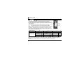
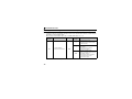
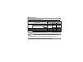
Inverter model
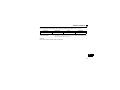
The inverter models 55K and 75K stated in this Instruction Manual differ according to -NA, -EC, -CH(T)
versions. Refer to the following correspondence table for each inverter model. (Refer to the instruction
manual of each inverter for the inverter model.)
For example, "for the 75K or higher" indicates "for the FR-A740-01440-NA or higher" in the case of FRA740 of NA version.
NA
FR-F700
FR-A700
FR-F720-55K
FR-F720-75K
FR-F740-55K
FR-F740-75K
FR-A720-55K
FR-A720-75K
FR-A740-55K
FR-A740-75K
FR-F720-02330-NA
FR-F720-03160-NA
FR-F740-01160-NA
FR-F740-01800-NA
FR-A720-02150-NA
FR-A720-02880-NA
FR-A740-01100-NA
FR-A740-01440-NA
EC
⎯
⎯
FR-F740-01160-EC
FR-F740-01800-EC
⎯
⎯
FR-A740-01800-EC
FR-A740-02160-EC
CH
⎯
⎯
FR-F740-55K-CH(T)
FR-F740-S75K-CH(T)
⎯
⎯
FR-A740-55K-CHT
FR-A740-75K-CHT
1
1
PRE-OPERATION INSTRUCTIONS
1.2
Unpacking and product confirmation
Take the plug-in option out of the package, check the product name, and confirm that the product is as you
ordered and intact.
This product is a plug-in option dedicated for the FR-A700/A701/F700(P)/FP700 series.
1.2.1
SERIAL number check
"Cumulative power (nvoDrvRunPower_l)" (page 59) can be monitored in 0.1kWh increments and the
"reference speed setting (nciNmlSpeed)" (page 106) can be set with the number of motor poles for the FRF700 series inverters with the following SERIAL or later.
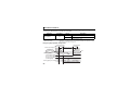
Check the SERIAL number indicated on the rating plate or package.
⋅ 55K or lower...in and after September 2004,
75K or higher...in and after August 2004
z SERIAL number check
Refer to the Instruction Manual of the inverter for the location of the rating plate.
Rating plate example
Symbol
4
Year
9
Month
{{{{{{
Control number
SERIAL (Serial No.)
The SERIAL consists of one symbol, two characters indicating production year and month,
and six characters indicating control number.
The last digit of the production year is indicated as the Year, and the Month is indicated by
1 to 9, X (October), Y (November), or Z (December).
2
PRE-OPERATION INSTRUCTIONS
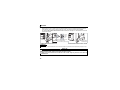
1.2.2
Product confirmation
Check the enclosed items.
Plug-in option ................... 1 Mounting screw (M3 × 6mm) Hex-head screw for option Communication option LED
.............. 2 (Refer to page 9.) mounting (5.5mm)
display cover.................... 1
............... 1 (Refer to page 9.) (Refer to page 8.)
5.5mm
1
Terminal block .................. 1 Neuron® ID bar code sticker
(Refer to page 15.)
......................................... 1
(Since one bar code sticker
is for maker duplicate, three
stickers are provided.)
REMARKS
• Echelon®, LONWORKS®, LonMaker®, LONMARK® and Neuron® are registered trademarks of Echelon Corporation in
the U.S.A. and other countries. Company and product names herein are the trademarks and registered trademarks
of their respective owners.
3
PRE-OPERATION INSTRUCTIONS
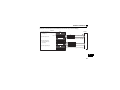
1.3
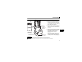
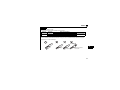
Parts
Communication connector
Mount the accessory terminal
block to connect to the network.
Operation status indication LED
Lit/flicker/off of the LED indicate inverter
operation status.(Refer to page 5.)
Front view
Rear view
RUN L.RUN
RX
TX
Mounting
hole
WINK SERVICE
FR-A7NL
Mounting
hole
Service switch
Press when making an initial
setting with the network
management computer.
Switch for manufacturer setting
Do not change the initial setting (OFF).
Terminal layout
NET_A
NET_B
O
N
Connector
Connect to the inverter
option connector.
(Refer to page 9.)
Mounting
hole
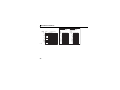
1
Switch for manufacturer setting
Do not change the initial setting (OFF). 2
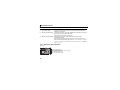
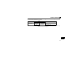
SERIAL
1
7
{{{
Symbol Year Month Control number
O
N
SERIAL
The SERIAL consists of one symbol, two characters indicating production
year and month, and three characters indicating control number.
The last digit of the production year is indicated as the Year, and the
Month is indicated by 1 to 9, X (October), Y (November), or Z (December).
4
PRE-OPERATION INSTRUCTIONS
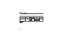
1.4 Operation status indication LED
Operation status indication LEDs indicate the operating status of the option unit according to the indication
status.
Check the position of LEDs on page 4.
Name
RUN L.RUN
RX
ON
OFF
ON
OFF
ON
Normal operation
Alarm (watchdog timer expiration etc.) detection
Normal operation
Alarm detection
L.RUN
Display the handshaking
status with the inverter.
RX
Display the receiving status
of packet from the network.
(for about 50ms)
TX *1
Display the transmission
status of packet to the
network.
(for about 50ms)
WINK
Display the receiving status
of WINK message from the
network.
TX
WINK SERVICE
SERVICE
*1
Status
Display the unit operation
status.
RUN L.RUN
RX
LED Status
RUN
TX
WINK SERVICE
Function
Display the status of node
and service switch.
OFF
ON
Receiving
1
Stop receiving
Transmitting
OFF
Stop transmission
Flicker three
Receiving WINK message
times
OFF
ON
Flicker
OFF
Stop
Service switch pressed status
Unconfigured status
Configured status
TX LED turns ON when the inverter autonomously sends data due to heartbeat and event driven functions even
when the communication cable is not wired.
5
PRE-OPERATION INSTRUCTIONS
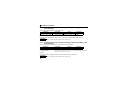
1.5 Specifications
1.5.1
Inverter option specifications
Inverter plug-in option type (can be mounted/dismounted to/from the inverter front
face)
Number of nodes occupied One inverter occupies one node.
Connection Free topology Twisted pair cable equivalent to EBT0.65mm × 1p *1
cable
Bus topology Twisted pair cable equivalent to EBT1.3mm × 1p *2
*1 Commercially available product: F-LINK-L(1F) by Fujikura Ltd.
*2 Commercially available product: F-LINK-L 1.25(1S) by Fujikura Ltd.
Type
1.5.2
Communication specifications
Number of units connected 64 units maximum including the inverter in the
Communication speed 78kbps
Free topology (connect a terminating resistor
at any one point)
Maximum: 500m
Maximum
cable length
<Example>
Event
reception and
transmission
6
Bus topology (connect a terminating resistor
at both ends)
Maximum: 2700m (The total length of each
node stub should be 3m maximum.)
<Example>
Terminating
resistor
Event
reception
same segment.
Stub
Terminating
resistor
Terminating
resistor
Number of events receivable at a time : 20
Reception time per event : 100ms maximum (when not conflicting with event transmission)
Transmission time per event
Event
⋅ Without bind : 200ms
transmission ⋅ With bind : [retry interval time] × [number of retries]
2
INSTALLATION
2.1
Pre-installation instructions
Make sure that the input power of the inverter is OFF.
CAUTION
Do not mount or remove the plug-in option while the power is being input. Otherwise, the
inverter and plug-in option may be damaged.
Static electricity in your body must be discharged before you touch the product. Otherwise the
product may be damaged.
2
7
INSTALLATION
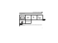
2.2
Installation of the communication option LED display cover
Mount the cover for displaying the operation status indication LED for the communication option on the
inverter front cover.
1)Cut off hooks on the rear of the inverter front
cover with nipper, etc. and open a window for
fitting the LED display cover.
2)Fit
the communication option LED display
cover to the front of the inverter front cover
and push it into until fixed with hooks.
Cut off with a nipper, etc.
Fit it so that the position of
lenses is in the upper-right
of the LED display cover.
When attached
Cut off with a nipper, etc.
CAUTION
Take caution not to hurt your hand and such with portions left by cutting hooks of the rear of
the front cover.
8
INSTALLATION
2.3
Installation procedure
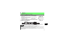
1) Remove the inverter front cover.
1)
2) Mount the hex-head screw for option
mounting into the inverter screw hole
(on earth plate) (size 5.5mm, tightening
torque 0.56Nxm to 0.75Nxm).
Screw hole for
option mounting
Inverter side
option
connector
3)
Screw hole for
option mounting
(on earth plate)
Hex-head screw
for option mounting
2)
_A
NET
_B
NET
FG
4) Mounting
3) Securely fit the connector of the plug-in
option to the inverter connector along
the guides.
4) Securely fix the both right and left sides
of the plug-in option to the inverter with
the accessory mounting screws.
(Tightening torque 0.33Nxm to
0.40Nxm)
If the screw holes do not line up, the
connector may not have been plugged
securely. Check for loose plugging.
screws
REMARKS
• Remove a plug-in option after removing two screws on both left and right sides.
(The plug-in option is easily removed if the control circuit terminal block is removed before.)
9
2
INSTALLATION
CAUTION
•
•
•
One of "
to
" (option fault) appears when the inverter cannot
recognize the option because it is improperly mounted, etc. Different
indication will appear according to the mounted position (connector 1, 2, or 3).
For an inverter having several option connectors, use the bottom connector to
mount the option.
Connector 1
If it is connected to a connector other than the bottom connector, "
Connector 2
"
" (option fault) will appear and its operation will be disabled.
Different indication will appear according to the mounted position (connector
1 or 2).
The number of available option connectors differs by the model. The table
below shows how the fault indication differs according to the number of connectors and their mounting positions.
Number of option
connectors
Mounting position
and fault indication
•
•
" or
3
Connector 1
(top connector)
Connector 2
(middle connector)
Connector 3
(bottom connector)
Connector 3
Example of FR-A700
2
1
Connector 1
(top connector)
Connector 2
(bottom connector)
⎯
Connector 1
⎯
⎯
⎯
⎯
⎯
(Refer to Chapter 1 of the Instruction Manual of the inverter for the number of option connectors.
Take caution not to drop a hex-head screw for option mounting or mounting screw during mounting and
removal.
Pull the option straight out when removing. Otherwise, the connector may be damaged.
10
3
WIRING
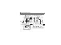
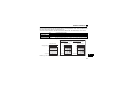
3.1 System configuration example
(1) Mount the communication option (FR-A7NL) on the inverter. (Refer to page 9.)
(2) Connect the LONWORKS node, option unit, network management
+
computer, and terminating resistor with the cable for LONWORKS
C1
communication.
Minimum 100 F, 50V(min)
Select a terminating resistor so that resistance values of R of the RC
R
network are the same as shown below.
⋅ Free topology (Refer to page 6) ......................... R = 52.3Ω ±1% 1/8W
⋅ Bus topology (Refer to page 6) .......................... R = 105Ω ±1% 1/8W
Network connection
(3) Install the network management tool on the network management computer
to assign the network address and bind (association function) the network
variable, etc. to the LONWORKS node.
(Example) Bus topology (without stub)
Terminating
resistor
Network
management
computer
NETA
NETB
LONWORKS
node
LONWORKS
node
NETA
NETA
NETB
NETB
Minimum 100 F, 50V(min)
C2
+
RC network
Inverter
FR-A7NL
FR-A5NL
NETA NETB
NETA
NETB
Terminating
resistor
3
LOMWORKS cable
(twisted pair cable)
REMARKS
· The network management tool is not included with this product. Please purchase it separately.
For the network management tool, LonMaker by Echelon Co. is recommended.
· When the option unit has been replaced because of a fault or others, perform "Commission" or "Replace" from the
network management tool after switching on the inverter. After performing "Commission" or "Replace", reset the
inverter (switch power off once, then on again or turn the RES signal on).
· Use the network management computer in the earthed status. Use the isolated power supply if the computer can not
be earthed (grounded).
11
WIRING
3.2 Wiring
(1) Strip off the sheath of the cable for LONWORKS communication. If the length of the sheath peeled is
too long, a short circuit may occur among neighboring wires. If the length is too short, wires might come
off.
Use the recommended cables. (Refer to page 6)
Wire the stripped cable after twisting it to prevent it from becoming loose.
(Do not solder it.)
Cable stripping length
7mm
Use a blade type terminal as required.
12
WIRING
REMARKS
• Information on blade terminals
Commercially available product examples (as of Jul. 2010)
Wire Size
Blade Terminal Model
Maker
With insulation sleeve Without insulation sleeve
(mm2)
0.3, 0.5
AI 0,5-6WH
A 0,5-6
Phoenix Contact
M3
Co.,Ltd.
0.75
AI 0,75-6GY
A 0,75-6
Blade terminal crimping tool: CRIMPFOX 6T-F/6 (Phoenix Contact Co., Ltd.)
Insert wires to a blade terminal, and check that the wires come out for about 0 to 0.5 mm from a sleeve.
Check the condition of the blade terminal after crimping. Do not use a blade terminal of which the crimping is
inappropriate, or the face is damaged.
Terminal
Screw Size
ll
he
Unstranded
wires
ire
W
S
3
e
ev
m
.5m
o0
0t
e
Sl
Damaged
Crumpled tip
Wires are not inserted
into the shell
13
WIRING
(2) Loosen the terminal screw and insert the cable into the terminal.
Tighten the fastening screws to the recommended tightening torques. Leave the other end of the cable
unconnected.
Screw Size
Tightening Torque
Cable Size
Screwdriver
M3
0.5N⋅m to 0.6N⋅m
0.3mm2 to 0.75mm2
Small
flat-blade screwdriver
(Tip thickness: 0.4mm /tip width: 2.5mm)
CAUTION
⋅ Undertightening can cause cable disconnection or malfunction. Overtightening can cause a short circuit or
malfunction due to damage to the screw or unit.
<When using one twisted pair cable>
Twisted pair cable
To be connected
to other node
NET_A
NET_B
<When using two twisted pair cables>
Twisted pair cable
To be connected to
other node
NET_A
NET_B
REMARKS
⋅ Change the number of twisted pair cables to insert in NET_A and NET_B according to the system used.
14
WIRING
(3) Connect the terminal block to the connector for communication of the communication option.
_A
NET
_B
NET
3
15
WIRING
(4) For wiring of the inverter which has one front cover, route wires between the control circuit terminal
block and front cover. If wires cannot be routed between the control circuit terminal block and front
cover (approx 7mm), remove a hook of the front cover, and use the space became available.
For wiring of the inverter which has front cover 1 and 2, use the space on the left side of the control
circuit terminal block.
Cut off
with a
nipper,
etc.
Front cover
Cut off a hook on the inverter
front cover side surface.
(Cut off so that no portion is left.)
Inverter which has one front cover
Front cover 1
Front cover 2
Control circuit
terminal block
Inverter which has front covers 1 and 2
REMARKS
⋅ When the hook of the inverter front cover is cut off for wiring, the protective structure (JEM1030) changes to open
type (IP00).
CAUTION
When performing wiring using the space between the inverter front cover and control circuit
terminal block, take caution not to subject the cable to stress.
After wiring, wire offcuts must not be left in the inverter. They may cause an error, failure or
malfunction.
16
4
INVERTER SETTING
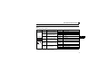
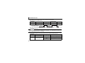
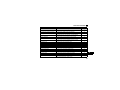
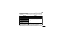
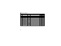
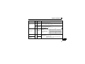
4.1 Parameter list
The following parameters are used for the communication option (FR-A7NL).
Perform setting as required.
Parameter
Number
79
338
339
340 *3
342
349 *1
387 *1
388 *1
389 *1
390 *1
391 *1
392 *1
500 *1
501
*1
502 *1, *3
*1
*2
*3
*4
550
*3
779
*4
Name
Operation mode selection
Communication operation command source
Communication speed command source
Communication startup mode selection
Communication EEPROM write selection
Communication reset selection
Initial communication delay time
Send time interval at heart beat
Minimum sending time at heart beat
% setting reference frequency
Receive time interval at heart beat
Event driven detection width
Communication error execution waiting time
Communication error occurrence count
display
Stop mode selection at communication error
NET mode operation command source
selection
Operation frequency during communication
error
Setting Range
0 to 4, 6, 7
0, 1
0, 1, 2
0, 1, 2, 10, 12
0, 1
0, 1
0 to 120s
0 to 999.8s
0 to 999.8s
1 to 400Hz
0 to 999.8s
0.00 to 163.83%
0 to 999.8s
Minimum
Refer
Initial Value
Setting
to Page
Increments
1
0
19
1
0
22
1
0
22
1
0
19
1
0
26
1
0
33
0.1s
0s
89
0.1s
0s
93
0.1s
0.5s
93
0.01Hz
60Hz/50Hz *2
91
0.1s
0s
103
0.01%
0%
108
0.1s
0
27
0
1
0
28
0, 1, 2, 3
1
0
28
0, 1, 9999
1
9999
22
0 to 400Hz, 9999
0.01Hz
9999
28
4
Parameters which can be displayed when the plug-in option (FR-A7NL) is mounted. (On the FR-F700P (FR-F700-NA) series
inverters, Pr. 502 appears even when no option is mounted.)
60Hz for the Japanese and NA models and 50Hz for the EC and CH models.
The setting is applied after an inverter reset or power-ON.
The setting is available for the FR-F700P (FR-F700-NA) series inverters.
17
INVERTER SETTING
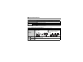
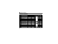
4.2
Operation mode setting
The inverter mounted with a communication option has three operation modes.
(1) PU operation [PU].............. Controls the inverter from the keys on the operation panel (FR-DU07)
mounted on the inverter.
(2) External operation [EXT] ... Controls the inverter by switching ON/OFF external signals connected to
the control circuit terminals of the inverter.
(The inverter is factory-set to this mode.)
(3) Network operation [NET] ... Controls the inverter with instructions from the network via the
communication option.
(The operation signal and running frequency can be entered from the
control circuit terminals depending on the Pr. 338 Communication operation
command source and Pr. 339 Communication speed command source settings.
Refer to page 23.)
4.2.1
Operation mode indicators
FR-DU07
Operation mode indicators
(The inverter operates according to the LED lit mode.)
PU: PU operation mode
EXT: External operation mode
NET: Network operation mode
18
INVERTER SETTING
4.2.2
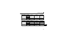
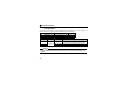
Operation mode switching and communication startup mode (Pr. 79, Pr. 340)
(1) Operation mode switching conditions
Before switching the operation mode, check that:
1) The inverter is at a stop;
2) Both the STF and STR signals are OFF; and
3) The Pr. 79 Operation mode selection setting is correct.
(Set with the operation panel of the inverter.)
Refer to the Instruction Manual of the inverter for details of Pr. 79.
(2) Operation mode selection at power-ON and at restoration from an instantaneous power
failure
The operation mode at power ON and at restoration from an instantaneous power failure can be selected.
Set a value other than "0" in Pr. 340 to select the Network operation mode.
After Network operation mode has started, parameter write from the network is enabled.
REMARKS
⋅ Change of the Pr. 340 setting is applied after power-ON or an inverter reset.
⋅ Pr. 340 can be changed with the operation panel in any operation mode.
4
19
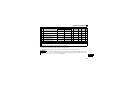
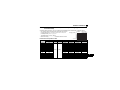
INVERTER SETTING
Pr. 340
Setting
Pr. 79
Setting
Operation Mode at Power on or Power
Restoration
0 (initial External operation mode
value)
1
PU operation mode
Operation Mode Switchover
Switching among the External, PU, and NET operation mode is enabled
*1
PU operation mode fixed
Switching between the External and Net operation mode is enabled
2
External
operation
mode
0
Switching to the PU operation mode is disallowed
3, 4
External/PU combined operation mode
Operation mode switching is disallowed
(initial
Switching among the External, PU, and NET operation mode is enabled
value)
6
External operation mode
while running.
X12 (MRS) signal ON .....external operation mode Switching among the External, PU, and NET operation mode is enabled *1
7
operation mode fixed (Forcibly switched to External operation
X12 (MRS) signal OFF....external operation mode External
mode.)
0
NET operation mode
1
PU operation mode
2
NET operation mode
3, 4
External/PU combined operation mode
Same as when Pr. 340 = "0"
1, 2 *2
NET operation mode
6 *4
X12 (MRS) signal ON..... NET operation mode
7
X12 (MRS) signal OFF....external operation mode
0
NET operation mode
Switching between the PU and NET operation mode is enabled *3
1
PU operation mode
Same as when Pr. 340 = "0"
2
NET operation mode
NET operation mode fixed
10, 12
3, 4
External/PU combined operation mode
Same as when Pr. 340 = "0"
*2
6 *4
NET operation mode
Switching between the PU and NET operation mode is enabled while running *3
7
External operation mode
Same as when Pr. 340 = "0"
*1 Operation mode cannot be directly changed between the PU operation mode and Network operation mode.
*2 The Pr. 340 settings "2, 12" are mainly used for communication operation using the inverter RS-485 terminals.
When a value other than "9999" (selection of automatic restart after instantaneous power failure) is set in Pr. 57 Restart coasting time, the
inverter will resume the same operation state which was in before, after power has been restored from an instantaneous power failure.
When Pr. 340 = "1, 10", a start command turns OFF if power failure has occurred and then restored during a start command is ON.
*3 Operation mode can be changed between the PU operation mode and Network operation mode with
on the operation panel (FR-
DU07) and X65 signal.
*4 Pr. 79 = "6" and Pr. 128 to Pr. 134 (PID control) are not activated simultaneously. Switchover mode and PID control are made invalid, and
the inverter performs the same operation as when "0" is set in Pr. 79.
20
INVERTER SETTING
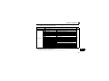
(3) Operation mode switching method
When "0, 1, or 2" is set in Pr. 340
External operation
Switching with the PU
Switching through the network
Switch to External
operation mode through
the network.
Press
Switch to the Network operation
mode through the network.
Press
PU to light
on
the PU to light
.
.
Network operation
When "10 or 12" is set in Pr. 340
on the
PU operation
Press of on the PU to light
.
Network operation
PU operation
Press of on the PU to light
4
.
For the switching method with the external terminal, refer to the Instruction Manual of the inverter.
Refer to page 47 and 81 for a switching method through the network.
CAUTION
⋅ When starting the inverter in the Network operation mode at power ON or an inverter reset, set a value other than 0
in Pr. 340. (Refer to page 19)
⋅ When setting a value other than 0 in Pr. 340, make sure that the initial settings of the inverter are correct.
21
INVERTER SETTING
4.3
Operation and speed command source (Pr. 338, Pr. 339, Pr. 550)
(1) Select command source for the Network operation mode (Pr. 550)
A control location for the Network operation mode can be selected from either the inverter RS-485
terminals or a communication option.
When using a communication option, set "0 or 9999 (initial value)" in Pr. 550.
Parameter
Number
Name
Initial Value
Setting
Range
0
1
550
NET mode operation
command source selection
9999
9999
Refer to the Instruction Manual of the inverter for details.
22
Description
Command source is at a
communication option
(Command source is not at inverter
RS-485 terminals)
Command source is at inverter RS485 terminals
(Command source is not at a
communication option)
Automatic recognition of the
communication option
Normally, command source is at RS485 terminals. When a
communication option is mounted,
the command source is at a
communication option.
INVERTER SETTING
(2) Selection of command source for the Network operation mode (Pr. 338, Pr. 339)
⋅ There are two command types: the start command, which controls the signals related to the inverter
start command and function selection, and the speed command, which controls signals related to
frequency setting.
⋅ In Network operation mode, commands from the external terminals and communication are as listed below.
Pr. 338 Communication operation
command source
Pr. 339 Communication speed
command source
Fixed
Running frequency from communication
functions
Terminal 2
(Functions
equivalent to Terminal 4
Terminal 1
terminals)
0
RL Low-speed operation command/
remote setting clear
operation command/
1 RM Middle-speed
remote setting deceleration
High-speed operation command/
2 RH remote setting acceleration
3
RT Second function selection
4 AU Terminal 4 input selection
5 JOG Jog operation selection
Selection of automatic restart after
6 CS instantaneous power failure, flying
start
7 OH External thermal relay input
Pr. 178 to Pr. 189 settings
Selective functions
Control
Location
Selection
8
REX 15-speed selection
9
X9 Third function
10 X10 Inverter run enable signal
11 X11 FR-HC connection, instantaneous
power failure detection
12 X12 PU operation external interlock
0:NET
0:
NET
NET
⎯
⎯
1:External
1:
2:
0:
External External NET
⎯
NET
NET
External
⎯
⎯
External
⎯
Compensation
1:
2:
External External
⎯
NET
External
⎯
External
NET
External
NET
External
NET
External
NET
External
External
NET
NET
⎯
NET
Combined
⎯
⎯
External
Remarks
Pr. 59 = "0"
(multi-speed)
Pr. 59 = "1, 2"
(remote)
External
Combined
External
4
External
External
NET
External
NET
NET
External
Pr. 59 = "0"
(multi-speed)
External
External
External
External
23
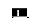
INVERTER SETTING
Control
Location
Selection
13 X13
14 X14
15 BRI
16 X16
17 X17
Pr. 178 to Pr. 189 settings
Selective functions
18 X18
19 X19
20 X20
22 X22
23 LX
24 MRS
0:NET
0:
NET
SQ Sequence start
1:External
1:
2:
External External
0:
NET
NET
NET
External
NET
1:
2:
External External
Remarks
External
NET
External
External
External
NET
External
NET
NET
External
External
NET
External
NET
NET
Combined
External
External
External
PU operation interlock
25 STOP Start self-holding selection
26 MC Control mode switchover
27 TL Torque limit selection
28 X28 Start time tuning
37 X37 Traverse function selection
42 X42 Torque bias selection 1
43 X43 Torque bias selection 2
44 X44 P/PI control switchover
50
24
Pr. 338 Communication operation
command source
Pr. 339 Communication speed
command source
External DC injection brake
operation is started
PID control valid terminal
Brake opening completion signal
PU-External operation switchover
Load pattern selection forward
rotation reverse rotation boost
V/F switchover
Load torque high speed frequency
S-pattern acceleration/deceleration
C switching terminal
Orientation command
Pre-excitation
Output stop
External
⎯
NET
NET
NET
NET
NET
NET
NET
External
External
External
External
External
External
External
External
External and NET*
External
Pr. 79 ≠ "7"
Pr. 79 = "7"
When the X12 signal
is not assigned
* The signal is valid
when there are
inputs from external
terminals and NET.
INVERTER SETTING
Pr. 178 to Pr. 189 settings
Selective functions
Control
Location
Selection
51
60
61
62
63
64
65
66
67
68
69
70
71
72
74
77
78
X51
STF
STR
RES
PTC
X64
X65
X66
X67
NP
CLR
X70
X71
X72
X74
X77
X78
Pr. 338 Communication operation
command source
Pr. 339 Communication speed
command source
Fault clear signal
Forward rotation command
Reverse rotation command
Inverter reset
PTC thermistor input
PID forward rotation action switchover
PU/NET operation switchover
External/NET operation switchover
Command source switchover
Conditional position pulse train sign
Conditional position droop pulse clear
DC feeding operation permission
DC feeding cancel
PID integral value reset
Magnetic flux decay output shutoff signal
Pre-charge end command
Second pre-charge end command
0:NET
0:
NET
NET
NET
NET
NET
1:
2:
0:
External External NET
Combined
NET
NET
External
External
External
NET
External
External
External
External
External
NET
NET
NET
External
NET
NET
External
NET
External
1:External
1:
2:
External External
External
External
External
Remarks
External
External
External
External
External
External
External
[Explanation of table]
External
:Control by signal from external terminal is only valid.
NET
:Control from network is only valid
Combined
:Operation from either external terminal or communication is valid.
⎯
:Operation from either external terminal or computer is invalid.
Compensation :Control by signal from external terminal is only valid if Pr. 28 Multi-speed input compensation setting is "1".
4
REMARKS
⋅ The Pr. 338 and Pr. 339 settings can be changed while the inverter is running when Pr. 77 = 2. Note that the setting
change is applied after the inverter has stopped. Until the inverter has stopped, communication operation command
source and communication speed command source before the setting change are valid.
⋅ Available signals vary with the inverter. Refer to the Instruction Manual of the inverter for the details.
25
INVERTER SETTING
4.3.1
Communication EEPROM write selection (Pr. 342)
When parameter write is performed from the communication option, write to RAM is enabled. Set when
frequent parameter changes are necessary.
Parameter
Number
342
Name
Communication EEPROM write
selection
Initial
Value
Setting
Range
0
0
1
Description
Parameter values written by
communication are written to the
EEPROM and RAM.
Parameter values written by
communication are written to the RAM.
⋅ When changing the parameter values frequently, set "1" in Pr. 342 to write them to the RAM.
Performing frequent parameter write with "0 (initial value)" (EEPROM write) set will shorten the life of the
EEPROM.
REMARKS
⋅ When "1" (write to RAM only) is set in Pr. 342, powering off the inverter will erase the changed parameter values.
Therefore, the parameter values available when power is switched ON again are the values stored in EEPROM
previously.
26
INVERTER SETTING
4.4
Operation at communication error occurrence
4.4.1
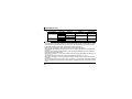
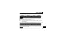
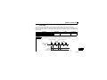
Operation selection at communication error occurrence (Pr. 500 to Pr. 502)
You can select operations at communication error occurrences by setting Pr. 500 to Pr. 502 under Network
operation.
(1) Waiting time for the communication line error output after a communication error
Waiting time for the communication error output after a communication line error occurrence can be set.
Parameter
Number
Name
Setting Range
Minimum Setting
Increments
Initial Value
500
Communication error
execution waiting time
0 to 999.8s
0.1s
0
Communication
line status
Communication error
(E.OP1, E.OP2 or E.OP3)
Alarm signal (LF)
(Pr. 502 = 3)
Normal
Error
Normal
Error
Recognition
Pr. 391
Pr. 500
setting time setting time
Pr. 500
Pr. 391
setting time setting time
ON
When a communication line error occurs and lasts longer than the time set in Pr. 500, it is recognized
as a communication error.
If the communication returns to normal within the time, it is not recognized as a communication error,
and the operation continues.
REMARKS
⋅ For detection of communication error, set the heartbeat receive time interval (Pr. 391) and set the send time interval
from the other node shorter than the heartbeat receive time interval.
When data is not received for more than the heartbeat receive time interval after the first reception, it is considered
as a communication line error, then "option fault (E.OP1, E.OP2 or E.OP3)" is displayed and the inverter stops.
(Refer to page 103.)
27
4
INVERTER SETTING
(2) Displaying and clearing the communication error count
The cumulative count of communication error occurrences can be displayed.
Write "0" to clear this cumulative count.
Parameter
Number
Name
Setting Range
Minimum Setting
Increments
Initial Value
501
Communication error
occurrence count display
0
1
0
Count timing depending on
communication line status
Normal
Error
Normal
Incremented by 1
Error
Incremented by 1
At the point of communication line error occurrence, Pr. 501 Communication error occurrence count
display is incremented by 1.
CAUTION
⋅ Communication error count is temporarily stored in the RAM memory. The error count is stored in EEPROM
only once per hour. If power reset or converter reset is performed, Pr. 501 setting will be the one that is last
stored to EEPROM depending on the reset timing.
(3) Inverter operation at a communication error occurrence
How the inverter operates at a communication line error or an option unit fault can be set.
Parameter
Number
Name
502
Stop mode selection at
communication error
779 *
Operation frequency during
communication error
Setting Range
0 (initial value), 1, 2, 3 Refer to page 29
0 to 400Hz
9999
(initial value)
* The setting is available for the FR-F700P (FR-F700-NA) series inverters.
28
Description
Motor runs at the specified frequency at
a communication error.
Motor runs at the frequency used before
the communication error.
INVERTER SETTING
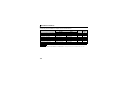
About setting
zOperation at an error occurrence
Error Definition
Communication line
Communication
option itself
Pr. 502 Setting
0
1
2
3
0, 3
1, 2
Operation
Indication
Fault Output
Continued *
Normal indication *
Not provided *
Coast to stop
E. 1, E. 2 or E. 3 lit
Provided
Decelerated to stop E. 1, E. 2 or E. 3 lit after stop Provided after stop
* When the communication returns to normal within the time period set in Pr. 500, the communication option error (E.OP1,
E.OP2 or E.OP3) does not occur.
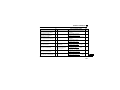
zOperation at error recognition after elapse of Pr. 500 time
Error Definition
Communication line
Communication
option itself
Pr. 502 Setting
Operation
Indication
0
1
2
3
0, 3
1, 2
Coast to stop
E.OP1, E.OP2 or E.OP3 lit
Fault Output
Provided
E.OP1, E.OP2 or E.OP3 lit Provided after stop
Decelerated to stop
after stop
Not provided
Continued *
Normal indication
Coast to stop
E. 1, E. 2 or E.3 lit
Provided
Decelerated to stop E. 1, E. 2 or E.3 lit after stop Provided after stop
* The FR-F700P (FR-F700-NA) series inverters operate according to the Pr.779 setting.
29
4
INVERTER SETTING
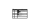
zOperation at error removal
Error Definition
Communication line
Communication
option itself
Pr. 502 Setting
0
1
2
3
0, 3
1, 2
Operation
Indication
Fault Output
Kept stopped
E.OP1, E.OP2 or E.OP3
kept lit
Kept provided
Restart
Operates normally
Normal indication
Not provided
Kept stopped
E. 1, E. 2 or E.3 kept lit
Kept provided
CAUTION
⋅ Communication line error [E.OP1 (fault data: HA1), E.OP2 (fault data: HA2) and E.OP3 (fault data: HA3)] are
errors that occur on the communication line. Communication option error [E. 1 (fault data: HF1), E. 2 (fault
data: HF2) and E. 3 (fault data: HF3)] are errors that occur in the communication circuit inside the option.
⋅ Fault output indicates the fault output signal (ALM signal) and fault bit output.
⋅ When the fault output setting is active, fault records are stored in the faults history.
When the fault output setting is not active, fault record is overwritten to the faults history temporarily but
not stored.
After the error is removed, the fault indication is reset, changing the display back to normal, and the last
fault is displayed in the faults history.
⋅ When the Pr. 502 setting is "1" or "2", the deceleration time is the ordinary deceleration time setting (e.g. Pr.
8, Pr. 44, Pr. 45 ).
⋅ The acceleration time at a restart is the ordinary acceleration time setting (e.g. Pr. 7, Pr. 44 ).
⋅ When the Pr. 502 setting is "2", the operation/speed command at a restart is the one given before the error
occurrence.
⋅ When a communication line error occurs at the Pr. 502 setting of "2", removing the error during deceleration
causes acceleration to restart at that point. (Acceleration is not restarted if the error is that of the option unit
itself.)
30
INVERTER SETTING
4.4.2
Fault and measures
(1) The inverter operates as follows at fault occurrences.
Fault
Location
Inverter
Status
Inverter operation
Data communication
Communication Inverter operation
line
Data communication
Communication option
Communication connection error
option
Error of communication
option itself
Inverter operation
Data communication
Inverter operation
Data communication
Network
Operation
Operation Mode
External
PU Operation
Operation
Inverter trip
Continued
Inverter trip
Continued
Inverter trip
Continued
Inverter trip *
Stop
Inverter trip *
Continued
Inverter trip *
Stop
Continued
Stop
Inverter trip *
Continued
Continued
Stop
Continued
Stop
Inverter trip *
Continued
Continued
Stop
* Depends on the Pr. 502 setting.
(2) Measures at error occurrences
Fault Indication
E.OP1, E.OP2,
E.OP3
E.1, E.2, E.3
Error Definition
Communication line
error
Option fault
Measures
Check the LED status on the option unit and remove the cause of the fault.
(Refer to page 5 for LED indication status)
Check the other nodes on the network.
Inspect the master.
Check the connection between the inverter and option unit for poor
contact, etc. and remove the cause of the error.
Mount the communication option to the bottom connector.
When faults other than the above are displayed, refer to the Instruction Manual of the inverter and remove the
cause of the error.
31
4
INVERTER SETTING
4.5
Inverter reset
(1) Operation conditions of inverter reset
Which resetting method is allowed or not allowed in each operation mode is described below.
Resetting Method
Inverter reset (Command request network variable)
(Refer to page 79) *1
Reset from the
Error reset at inverter fault
Pr.349 = 0
network
(Inverter input signal network variable)
Pr.349 = 1
(Refer to page 60) *2
Network
Operation
Enabled
Operation Mode
External
PU
Operation
Operation
Disabled
Disabled
Enabled
Enabled
Disabled
Disabled
Enabled
Enabled
Enabled
Enabled
Enabled
Enabled
Enabled
Enabled
Enabled
Turn ON the inverter RES signal (terminal RES)
Enabled
Switch OFF inverter power
Enabled
Enabled
Reset from the Inverter reset
PU/DU
Reset at inverter fault
Enabled
*1 Inverter reset can be made any time.
*2 Reset can be made only when the protective function of the inverter is activated.
CAUTION
⋅ When a communication line error has occurred, reset cannot be made from the network.
⋅ The inverter is set to the External operation mode if it has been reset in Network operation mode in the
initial status.
To resume the network operation, the inverter must be switched to the Network operation mode again.
Set a value other than "0" in Pr. 340 to start in the Network operation mode. (Refer to page 19.)
⋅ The inverter cannot be controlled for about 1s after release of a reset command .
32
INVERTER SETTING
(2) Error reset operation selection at inverter fault
When used with the communication option (FR-A7NL), an error reset command* from network can be
set invalid in the External operation mode or PU operation mode.
Parameter
Number
349
Name
Communication reset
selection
Initial
Value
Setting
Range
0
0
1
Function
Error reset* is enabled independently of
operation mode
Error reset* is enabled only in the network
operation mode
* nviInvAlarmReset (Refer to page 60.)
4
33
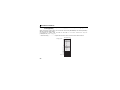
INVERTER SETTING
4.6
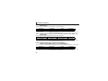
Frequency and speed settings
Frequency setting, monitoring, and parameter setting via FR-A7NL are always performed in 0.01Hz
increments regardless of the Pr. 37 Speed display setting.
The set speed and monitored values via FR-A7NL are converted to rotations per minute according to the
Pr. 144 Speed setting switchover setting as shown below.
Speed or monitored value (1r/min) = frequency × 120/number of motor poles (Pr.144*)
∗ When Pr. 144 = "102 to 110," the formula is calculated with the value of (Pr.144 - 100). When Pr. 144 = "0", the formula is calculated
with 4 poles.
REMARKS
⋅ Refer to the Instruction Manual of the inverter for the details of Pr.37 and Pr.144.
34
5
FUNCTION OVERVIEW
5.1 XIF file
Using the configuration software, network setting is easily done.
To use the configuration software, an XIF file is necessary. XIF file is used to recognize device features and
functions. For details of installation and XIF file usage, refer to the configuration software manual.
XIF file can be downloaded from
Mitsubishi Electric FA Network Service MELFANS web
http://www.MitsubishiElectric.co.jp/melfansweb or obtained from your sales representative.
CAUTION
⋅ Check the manufactured date of your FR-A7NL, and use the appropriate XIF file. (For how to find the SERIAL
number (manufactured date), refer to page 2.) An incorrect XIF file will disrupt normal operation. For details, refer to
MELFANS web or contact your sales representative.
⋅ Since memory for write enable application is not installed in the inverter, Mitsubishi does not provide application files
(file extensions such as .nxe, .apb).
5
35
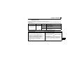
FUNCTION OVERVIEW
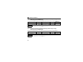
5.2 Output from the inverter to the network
Main items to be output from the inverter (FR-A7NL) to the network and their descriptions are explained
below.
Item
Object status
Speed monitor
Inverter output signal
Output frequency monitor
Output current monitor
Output voltage monitor
Actual operation time monitor
Cumulative power monitor
Fault occurrence definition
Product information
Emergency stop status
Fault status
Monitor data
Command reply
36
Description
You can check the condition of the node.
You can monitor the output frequency in 0.005% increments.
You can monitor the output terminal status of the inverter.
You can monitor the output frequency in 0.1/0.01Hz or 0.005%
increments.
You can monitor the output current in 0.1A increments.
You can monitor the output voltage in 0.1V increments.
You can monitor the actual operation time of the inverter.
You can monitor the cumulative power of the inverter.
At inverter fault occurrence, you can confirm the fault definition.
You can output the maker name and type as a character string.
You can confirm the emergency stop status of the inverter.
You can check whether the inverter is in the fault status or not.
You can check the monitor value corresponding to the monitor code set.
You can check the replies to command requests, such as operation
mode selection, parameter write, and inverter reset, from the inverter
in ASCII code.
Refer to
Page
48
51
53
56, 57, 78
58
58
58
59
61
64
66
67
77
86
FUNCTION OVERVIEW
Item
Command reply (binary)
Description
You can check the replies to command requests, such as operation
mode selection, parameter write, and inverter reset, from the inverter
in binary code.
A command reply in binary code requires less communication data
amount than a command reply in ASCII code does.
Refer to
Page
87
REMARKS
⋅ Refer to the Instruction Manual of the inverter for functions controllable from the network in each operation mode.
5
37
FUNCTION OVERVIEW
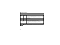
5.3 Input from the network to the inverter
Main items which can be commanded from the network to the inverter and their descriptions are explained
below.
Item
Object request
Start and stop/simple speed setting
Speed adjustment
Inverter input signal
Set frequency write destination
selection
Set frequency
Fault reset
Emergency stop command
PID set point
PID measured value
PID deviation
Monitor code
Command request
Command request (binary)
38
Description
You can make a request to know the object status.
You can perform start/stop and simple frequency setting.
You can perform frequency setting in 0.005% increments.
You can execute functions assigned to the inverter input terminals.
You can select either of RAM or EEPROM as the write
destination of set frequencies.
You can set the set frequency in 0.1/0.01Hz or 0.005% increments.
You can reset the inverter at an inverter fault occurrence.
You can make an emergency stop of the inverter.
You can input the set point for PID control.
You can input the current measured value for PID control.
You can input the current deviation for PID control.
You can input a code to select a monitor type.
You can make command requests, such as operation mode
selection, parameter write, inverter reset, to the inverter in
ASCII code.
You can make command requests, such as operation mode
selection, parameter write, or inverter reset, to the inverter in
binary code.
A command request in binary code requires less
communication data amount than a command request in ASCII
code does.
Refer to
Page
47
49
50
52
54
55, 78
60
65
69
70
71
72
79
80
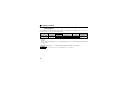
FUNCTION OVERVIEW
Item
Initial communication delay time
Forward/reverse rotation prevention
% setting reference frequency
Maximum frequency
Minimum frequency
Heartbeat send time interval
Minimum heartbeat send time
Acceleration time
Deceleration time
PID action selection
PID proportional band
PID integral time
PID differential time
PID manipulated bias
PID manipulated gain
Heartbeat receive time interval
Maximum speed
Minimum speed
Reference speed setting
Description
You can set the time from when the inverter starts until when
data is sent to the network.
You can prevent rotation in the wrong direction.
You can set the reference frequency of set frequency
(nviInvSetFreqP) and output frequency (nvoInvOutFreqP).
You can set the maximum frequency of the inverter.
You can set the minimum frequency of the inverter.
You can set the heartbeat send time interval of output network
variables.
You can set the minimum heartbeat send time of output
network variables.
You can set the motor acceleration time.
You can set the motor deceleration time.
You can choose the operation of PID control.
You can set the proportional band for PID control.
You can set the integral time for PID control.
You can set the differential time for PID control.
You can set the manipulated variable at 0%.
You can set the manipulated variable at 100%.
You can set the heartbeat receive time interval of input network
variables.
You can set the maximum speed of the inverter.
You can set the minimum speed of the inverter.
You can set the reference speed of maximum speed, minimum
speed, speed adjustment, speed monitor.
Refer to
Page
89
90
91
92
92
93
93
96
97
98
100
100
101
101
102
103
5
105
105
106
39
FUNCTION OVERVIEW
Item
Reference frequency setting
Default value of speed adjustment
Event driven detection width
Description
You can set the reference frequency of maximum speed,
minimum speed, speed adjustment, speed monitor.
You can set the default value of speed adjustment.
You can set the event driven detection width of the monitorrelated output network variables.
Refer to
Page
107
107
108
REMARKS
⋅ Refer to the Instruction Manual of the inverter for functions controllable from the network in each operation mode.
40
6
NETWORK VARIABLES
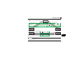
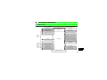
6.1 Object map
This chapter describes detailed object definitions for use of LONWORKS system.
Input network variables
Object request
Start/stop and simple speed setting
Speed adjustment
Inverter input signal
Set frequency write destination selection
Set frequency (0.1Hz/bit)
Set frequency (0.005%/bit)
Node object
Variable Speed Motor Drive
object
Inverter
basic
functions
Fault reset
Inverter object
Inverter
extended
functions
Speed monitor
Inverter output signal
Output frequency monitor (0.1Hz/bit)
Output frequency monitor (0.005%/bit)
Output current monitor (0.1A/bit)
Output voltage monitor (0.1V/bit)
Actual operation time monitor (1h/bit)
Cumulative power monitor (1kWh/bit)
Cumulative power monitor 2 (0.1kWh/bit)
Fault occurrence definition (string)
Product information(maker name,model)(string)
Emergency stop status
Fault status
Emergency stop command
Inverter PID
control
functions
Output network variables
Object status
PID set point (0.005%/bit)
PID measured value (0.005%/bit)
PID deviation (0.005%/bit)
Monitor code
Set frequency (0.01Hz/bit)
Command request
Command request (binary)
Monitor data
Output frequency monitor (0.01Hz/bit)
Command reply
Command reply (binary)
6
Configuration properties
41
NETWORK VARIABLES
6.2 Network variable list
No. Type
*4
1
2
3
4
5
6
7
8
9
Function
SN Object request
SN Object status
Start/stop and simple speed
SN setting
SN Speed adjustment
SN Speed monitor
SN Inverter input signal
SN Inverter output signal
Set frequency write destination
SN
selection
SN Set frequency (0.1Hz/bit) *1
10 SN Set frequency (0.005%/bit)
11 SN
12 SN
13
14
15
16
42
SN
SN
SN
SN
Output frequency monitor
(0.1Hz/bit) *1
Output frequency monitor
(0.005%/bit)
Output current monitor (0.1A/bit) *1
Output voltage monitor (0.1V/bit) *1
Actual operation time monitor (1 h/bit)
Cumulative power monitor(1kWh/bit)
Network Variables
Variables
Name
SNVT_obj_request nviRequest
SNVT_obj_status nvoStatus
Setting Value
Size
Storage
(byte)
Location
In
3
Out
6
In/
Out
In
SNVT_switch
nviDrvSpeedStpt
SNVT_lev_percent
SNVT_lev_percent
SNVT_state
SNVT_state
nviDrvSpeedScale In
nvoDrvSpeed
Out
nviInvInputSig
In
nvoInvOutputSig Out
SNVT_switch
nviInvSetFreqSw
In
SNVT_freq_hz
nviInvSetFreq
In
SNVT_lev_percent nviInvSetFreqP
SNVT_freq_hz
nvoInvOutFreq
In
Out
SNVT_lev_percent nvoInvOutFreqP Out
SNVT_amp
SNVT_volt
SNVT_time_hour
SNVT_elec_kwh
nvoDrvCurnt
nvoDrvVolt
nvoDrvRunHours
nvoDrvRunPower
2
2
100.00%
55
2
0.0Hz
56
2
0.000%
57
2
2
2
2
0.0A
0.0V
0h
0kWh
58
58
58
59
2
2
2
2
2
RAM/
EEPROM of
the inverter
⎯
Out
Out
Out EEPROM of
Out the inverter
Refer
to
Page
47
48
H0
H0
state=HFF
value=0
100.00%
0.000%
0
H8000
state=H0
value=0
H7FFF
2
⎯
Initial
Value
49
50
51
52
53
54
55
NETWORK VARIABLES
No. Type
*4
Function
17 SN Fault reset
occurrence definition
18 SN Fault
(string)
information (maker
19 SN Product
name, type) (string)
20 SN Emergency stop command
21 SN Emergency stop status
Network Variables
Variables
Name
In/ Setting Value Size
Storage
Out Location
(byte)
Initial
Value
Refer
to
Page
SNVT_switch
nviInvAlarmReset
In
2
state=H0
value=H0
60
SNVT_str_asc
nvoInvAlarmStr
Out
31
0
61
SNVT_str_asc
nvoInvTypeInfo
Out
31
SNVT_hvac_emerg nviEmergOverride In
SNVT_hvac_emerg nvoEmergStatus Out
1
1
22 SN Fault status
SNVT_switch
23 SN PID set point (0.005%/bit)
PID measured value
24 SN (0.005%/bit)
25 SN PID deviation (0.005%/bit)
26 SN Monitor code
27 SN Monitor data
SNVT_lev_percent nviInvPIDTarget
In
2
MITSUBISHI
FR-A7NL
H0
H0
state=H0
value=H0
0.000%
SNVT_lev_percent nviInvPIDValue
In
2
0.000%
70
SNVT_lev_percent nviInvPIDDev
SNVT_count
nviInvMonCode
SNVT_count
nvoInvMonData
In
In
Out
2
2
2
0.000%
0
0
71
72
77
28 SN Set frequency (0.01Hz/bit)
SNVT_count
nviInvSetFreq2
2
0.00Hz
78
SNVT_count
nvoInvOutFreq2
2
0.00Hz
78
31
31
0
0
79
86
2
0s
89
Output frequency monitor
29 SN (0.01Hz/bit)
30 SN Command request
31 SN Command reply
32 SC Initial communication delay time
(0.1s/bit)
SNVT_str_asc
SNVT_str_asc
nvoDrvAlarm
Out
RAM/
In EEPROM of
the inverter
Out
nviInvCmdReq
In
nvoInvCmdReply Out
SNVT_time_sec nciPwUpOutTm
⎯
In
⎯
Pr. 387
2
64
65
66
67
69
43
6
NETWORK VARIABLES
No. Type
*4
Function
33 SC
Forward/reverse rotation
prevention
% set reference frequency
(0.1Hz/bit) *1
Maximum frequency (0.1Hz/bit) *1
Minimum frequency (0.1Hz/bit) *1
Heartbeat send time interval
(0.1s/bit)
Minimum heartbeat send time
(0.1s/bit)
Acceleration time (0.1s/bit)
Deceleration time (0.1s/bit)
PID action selection
PID proportional band (0.1%/bit)
PID integral time (0.1s/bit)
PID differential time (0.1s/bit) *1
PID manipulated variable bias
(0.1Hz/bit) *1
PID manipulated variable gain
(0.1Hz/bit) *1
Heartbeat receive time interval
(0.1s/bit)
Maximum speed (0.005%/bit)
Minimum speed (0.005%/bit)
34 SC
35 SC
36 SC
37 SC
38 SC
39
40
41
42
43
44
SC
SC
SC
SC
SC
SC
45 SC
46 SC
47 SC
48 SC
49 SC
44
Network Variables
Variables
Name
In/ Setting Value Size
Storage
Out Location
(byte)
Initial
Value
Refer
to
Page
*2
90
SNVT_count
nciInvFwdRevLock
In
Pr. 78
2
SNVT_freq_hz
nciInvSetFreqBas
In
Pr. 390
2
SNVT_freq_hz
SNVT_freq_hz
nciInvMaxFreq
nciInvMinFreq
In
In
Pr. 1
Pr. 2
2
2
SNVT_time_sec nciSndHrtBt
In
Pr. 388
2
0
93
SNVT_time_sec nciMinOutTm
In
Pr. 389
2
0.5s
93
SNVT_time_sec
SNVT_time_sec
SNVT_count
SNVT_count
SNVT_time_sec
SNVT_time_sec
nciRampUpTm
nciRampDownTm
nciInvPIDSwitch
nciInvPIDPro
nciInvPIDIntTm
nciInvPIDDiffTm
In
In
In
In
In
In
2
2
2
2
2
2
*2
*2
96
97
98
100
100
101
SNVT_freq_hz
nciInvPIDOpeBias
In
2
*2
101
SNVT_freq_hz
nciInvPIDOpeGain
In
Pr. 7
Pr. 8
Pr. 128
Pr. 129
Pr. 130
Pr. 134
C2
(Pr. 902)
Pr.125
(Pr. 903)
2
*2
102
60Hz
<50Hz> *3 91
*2
92
*2
92
*2
*2
*2
*2
SNVT_time_sec nciRcvHrtBt
In
Pr. 391
2
0s
103
SNVT_lev_percent nciMaxSpeed
SNVT_lev_percent nciMinSpeed
In
In
Pr. 1
Pr. 2
2
2
*2
105
105
*2
NETWORK VARIABLES
No. Type
*4
50 SC
Function
Reference speed setting
(1r/min/bit)
Reference frequency setting
51 SC (0.1Hz/bit) *
1
52 SC Speed adjustment default value
Event driven detection width
53 SC
(0.005%/bit)
54 SN Cumulative power monitor 2
(0.1kWh/bit)
55 SN Command request (binary)
56 SN Command reply (binary)
57
to
62
*1
*2
*3
*4
Network Variables
Variables
Name
In/ Setting Value Size
Storage
Out Location
(byte)
Initial
Value
Refer
to
Page
1800r/min
<1500r/min> 106
*3
60Hz
<50Hz> *3 107
100.00% 107
SNVT_rpm
nciNmlSpeed
In
Pr. 390
2
SNVT_freq_hz
nciNmlFreq
In
Pr. 390
2
SNVT_lev_percent nciDrvSpeedScale
In
⎯
2
SNVT_lev_percent nciInvEvtDuty
In
Pr. 392
2
0%
108
EEPROM of
the inverter
4
0kWh
60
⎯
⎯
14
14
0
0
80
87
SNVT_elec_kwh_l nvoDrvRunPower_l Out
SNVT_preset
SNVT_preset
nvilnvCmdBinReq
In
nvolnvCmdBinRply Out
System reserved
Displayed in 0.01 increments on the operation panel (FR-DU07).
Refer to the Instruction Manual of the inverter for the corresponding parameter initial values.
Values within parenthesis are initial values for EC and CH versions.
SN denotes "SNVT" (standard network variable). SC denotes "SCPT" (configuration property).
REMARKS
• Write conditions of configuration property is same as those of the inverter parameter. Write conditions are restricted
by Pr. 77 Parameter write selection. When writing to configuration property during inverter operation, set "2" in Pr. 77.
Refer to the Instruction Manual of the inverter for details of Pr. 77.
45
6
NETWORK VARIABLES
6.3 LONWORKS object
6.3.1
Setting range of object ID
The setting values of object ID are 0 to 4 and are as listed below.
When any values 5 to 65535 are set for object ID, invalid_id bit of object status (nvoStatus) becomes 1 and
a command set for object request is made invalid. (Refer to page 48)
Object ID
0
1
2
3
4
46
Description
Node object
Variable speed motor drive object [LONMARK object]
Inverter basic function
Inverter PID control function
Inverter extended function
NETWORK VARIABLES
6.3.2
Object request (network input SNVT_obj_request nviRequest)
You can make a request to get the object status.
Member Name
Description
object_id
object_request
*1
*2
*3
Initial
Value
Stores the object ID.
H0
RQ_NORMAL
H1
H2
H3
H4
RQ_DISABLED
RQ_UPDATE_STATUS
RQ_SELF_TEST
RQ_UPDATE_ALARM
H5
RQ_REPORT_MASK
H6
H7
H8
H9
HA
HB
HC
HD
HE
HF
HFF
⎯
RQ_OVERRIDE
RQ_ENABLE
RQ_RMV_OVERRIDE
RQ_CLEAR_STATUS
RQ_CLEAR_ALARM
RQ_ALARM_NOTIFY_ENABLED
RQ_ALARM_NOTIFY_DISABLED
RQ_MANUAL_CTRL
RQ_REMOTE_CTRL
RQ_PROGRAM
RQ_NUL
Other than the above
In external operation mode *3, it shifts to the network
operation mode.
Makes the inverter object invalid.
Update object status (nvoStatus).
Not supported.*1
Updates in_alarm bit of the object status (nvoStatus).
Changes bit (invalid_id, invalid_request, disabled,
manual_control, in_alarm, in_override, report_mask)
supported by object status (nvoStatus) to "1".
Not supported.*1
Makes the inverter object valid.
Not supported.*1
Clears all bits of the object status (nvoStatus) to "0".
Clears in_alarm bit of object status (nvoStatus) to "0".*2
H0
Not supported. *1
Shifts the inverter to the external operation mode.
Shifts the inverter to the network operation mode.
Not supported.*1
Nothing is done.
Not supported. *1
Changes the invalid_request of the object status (nvoStatus) to "1" when data is set. (Refer to page 48)
Use fault reset (nviInvAlarmReset) to reset the fault status of the inverter (Refer to page 60.)
Can also be switched from switchover mode.
(For details of switchover mode, refer to the Instruction Manual of the inverter.)
6
47
NETWORK VARIABLES
6.3.3
Object status (network output SNVT_obj_status nvoStatus)
You can indicate the condition of the node.
Member Name
object_id
invalid_id
invalid_request
disabled
out_of_limits
open_circuit
out_of_service
Mechanical_fault
feedback_failure
over_range
under_range
electrical_fault
unable_to_measure
comm_failure
fail_self_test
self_test_in_progress
locked_out
manual_control
in_alarm
in_override
report_mask
programming_mode
programming_fail
alarm_notify_disabled
Description
The setting value of object request (nviRequest) written to object_id is displayed.
Changes to "1" if an illegal object ID is specified in object_id of the object request
(nviRequest),
Changes to "1" if object_request not supported by the object request (nviRequest) is set.
Changes to "1" if the object of the inverter is invalid.
Not supported. *
H0
Changes to "1" if the operation mode of the inverter is other than the network operation
mode.
Changes to "1" during the inverter is in the fault status.
Changes to "1" if the operation mode of the inverter is network operation mode and run
command and speed command are not given via the network.
Not supported.
*
* "0" is always set in the unsupported functions bit position.
48
Initial Value
NETWORK VARIABLES
6.4 Variable speed motor drive object
6.4.1
Start/stop and simple speed setting (network input SNVT_switch
nviDrvSpeedStpt)
You can set "start/stop" and "simple setting of set frequency".
⋅ Set start/stop in state.
The rotation direction (forward/reverse rotation) is determined by whether "speed adjustment
(nviDrvSpeedScale)" is positive or negative. (Refer to page 50)
⋅ Set simple speed setting in value.
As the set frequency, set its ratio to "speed adjustment (nviDrvSpeedScale)" (0.5% increments).
nviDrvSpeedStpt
State
Value
H0
H1
Operation *
nviInvSetFreq = "H7FFF"
NA
0
Run at a 0% frequency.
(initial value)
H2 to HFF
(initial value:
HFF)
0.5 to
100%
NA
nviInvSetFreq = "0Hz to 400Hz"
Stop
Run at a 0.5 to 100% frequency.
(nciNmlFreq × nviDrvSpeedStpt × nviDrvSpeedScale)
Run at an nviInvSetFreq frequency.
No operation
* Operation of nviDrvSpeedStpt differs according to nviInvSetFreq. (Refer to page 55)
REMARKS
· The variable is initialized to "HFF" at power-on or if it is not updated at the "heartbeat receive time interval (nciRcvHrtBt)"
(refer to page 103).
6
· The inverter operates at 100% frequency even if the value exceeding "100%" is set when state = "H1".
· Updating nviDrvSpeedScale resets the start command depending on the state of nviDrvSpeedStpt.
49
NETWORK VARIABLES
6.4.2
Speed adjustment (0.005% increments) (network input
SNVT_lev_percent nviDrvSpeedScale)
You can set the set frequency in 0.005% increments on the assumption that the frequency set in "reference
frequency setting (nciNmiFreq) is 100%. (Refer to page 107)
⋅ When the state of nviDrvSpeedStpt is H1, the motor is placed in forward rotation status if nviDrvSpeed
Scale value is positive and placed in reverse rotation status if the value is negative.
⋅ When state of nviDrvSpeedStpt is H0, the motor is at a stop status.
Data Name
Initial Value
Range
Increments
nviDrvSpeedScale
100.00% (NciDrvSpeedScale value)
(Refer to page 107)
-163.840% to 163.830%
0.005%/bit
⋅ Data acceptance timing ........... At network variable receive (nv_update_occurs event)
The frequency to be written to the inverter actually is as shown in the following formula.
Set frequency = | (reference frequency setting × speed adjustment × simple speed setting) |
Example:
When "Simple speed setting (nviDrvSpeed Stpt.value)" = 50%, "Reference frequency setting (nciNmlFreq)"
= 60.0Hz, and "Speed adjustment (nviDrvSpeedScale)" = -150%, output frequency is (60.00Hz × (-150%) ×
50%) = -45Hz. Therefore, a reverse command of 45Hz is given.
REMARKS
⋅ The variable is initialized to "100.00%" at power-on or if it is not updated within the set "heartbeat receive time
interval (nciRcvHrtBt)". (Refer to page 103)
⋅ Control can not be exercised at less than the minimum frequency resolution (0.01Hz) of the inverter.
⋅ To make the change of "reference frequency setting (nciNmlFreq)" reflected to the operation speed, a value is need
to be written to speed adjustment (nviDrvSpeedScale)
50
NETWORK VARIABLES
6.4.3
Speed monitor (0.005% increments) (network output SNVT_lev_percent
nvoDrvSpeed)
You can set the frequency command in 0.005% increments on the assumption that the frequency set in
"reference frequency setting (nciNmiFreq)" is 100%. (Refer to page 107)
⋅ A positive value indicates the motor is in the forward rotation status and a negative value indicates that
the motor is in the reverse rotation status.
Data Name
Initial Value
Range
Increments
nvoDrvSpeed
0.000%
-163.840% to 163.830%
0.005%/bit
⋅ Data send event ...................... When data changes in 0.005% increments
⋅ Data send timing ..................... As set in Pr. 388 Send time interval at heart beat and Pr. 389 Minimum sending
time at heart beat. (Refer to page 93)
Output frequency is as shown in the following formula.
Output frequency = | (reference frequency setting × speed monitor × simple speed setting) *|
* Refer to page 107 for reference frequency setting and page 49 for simple speed setting.
Example:
When "reference frequency setting (nciNmIFreq)" = 60.0Hz and "speed setting monitor (nvoDrvSpeed)" =
-150%, "simple speed setting (nviDrvSpeedStpt.value)" = 50%, output frequency is (60.0Hz × (-150%) ×
50%) = -45Hz.
Therefore, a reverse rotation of 45Hz is given.
6
REMARKS
⋅ Monitoring is disabled at less than the minimum frequency resolution (0.01Hz) of the inverter.
51
NETWORK VARIABLES
6.5 Inverter basic functions
6.5.1 Inverter input signal (network input SNVT_state nviInvInputSig)
A 16-bit-wide input signal to the inverter.
⋅ The initial value of all bits are "0".
⋅ Data acceptance timing ........... At network variable receive (nv_update_occurs event)
Bit
Signal Name
0
Forward rotation command *2
1
Reverse rotation command *2
2
3
4
5
6
7
8
*2
52
Stop command
Forward rotation start
Stop command
Reverse rotation start
A start command is input to the
inverter when the bit is 1.
A stop command is given when
both bits are 1.
High-speed operation command
(terminal RH function) *1
Middle-speed operation command
(terminal RM function) *1
Low-speed operation command
(terminal RL function) *1
JOG operation command (terminal JOG function) *1 Functions assigned to terminals RH, RM, RL, JOG, RT, AU, CS,
Second function selection (terminal RT function) *1 MRS, STOP, and RES are activated.
Current input selection (terminal AU function) *1
Selection of automatic restart after instantaneous
power failure (terminal CS function) *1
Output stop (terminal MRS function) *1
Start self-holding selection (terminal STOP function) *1
Inverter reset (RES terminal function) *1
9
10
11
12 to
Not used
15
*1
Description
0:
1:
0:
1:
System reserved
Signal names are initial values. Using Pr. 180 to Pr .189, you can change input signal functions. Note that some of
signals do not accept a command from the network according to the Pr. 338 and Pr. 339 settings. (Refer to page 23)
Refer to the Instruction Manual of the inverter for details of Pr. 180 to Pr. 189.
The signals set in Bit 0 and Bit 1 cannot be changed. Even if a setting is changed with Pr. 178 or Pr. 179, the
changed setting becomes invalid. Refer to the Instruction Manual of the inverter for the details of Pr. 178 and Pr. 179
NETWORK VARIABLES
6.5.2
Inverter output signal (network output SNVT_state nvoInvOutputSig)
A 16-bit-wide output signal to the inverter.
⋅ Data send timing ..................... As set in Pr. 388 Send time interval at heart beat and Pr. 389 Minimum sending
time at heart beat. (Refer to page 93)
Bit
Signal Name
0
During forward running
1
During reverse running
2
During running (terminal RUN function)
Description
0:
1:
0:
1:
Other than during forward running (during stop, during reverse running)
During forward running
Other than during reverse running (during stop, during forward running)
During reverse running
*1
3
4
Up to frequency (terminal SU function) *1
Overload alarm (terminal OL function) *1
Instantaneous power failure (terminal
5
IPF function) *1
Frequency detection (terminal FU
6
function) *1
7
Fault (terminal ABC1 function) *1
8
⎯ (terminal ABC2 function) *1
9 to 13 Not used
*1
*2
14
Error status flag
15
Ready signal
Functions assigned to terminals RUN, SU, OL, IPF, FU, ABC1 and ABC2
are activated.
System reserved
The bit is 1 when the output stops due to the occurrence of an inverter
fault. *2
The bit is 1 when the inverter becomes ready for operation after power-ON.
Signal names are initial values. Using Pr. 190 to Pr . 196, you can change output signal functions.
Refer to the Instruction Manual of the inverter for details of Pr. 190 to Pr. 196.
When the retry function is used, the signal turns on according to the retry setting. Refer to the Instruction Manual of
the inverter for the retry function.
53
6
NETWORK VARIABLES
6.5.3
Set frequency write destination selection (network input SNVT_switch
nviInvSetFreqSw)
When writing the set frequency of any of the following network variables, you can select either of the
internal memories of the inverter, RAM and EEPROM, as the write destination.
Target network variables
Increment
Refer to page
nvilnvSetFreq
nvilnvSetFreqP
nvilnvSetFreq2
0.1Hz
0.005%
0.01Hz
55
55
78
State
Value
H0 (initial value)
N/A
(not used/initial
value: 0)
H1
H2 to HFF
Write
Destination
Operation
Switching power OFF erases the written values. You can
prevent the write life of the EEPROM from becoming shorter.
RAM, EEPROM Switching power OFF does not erase the written value.
⎯
Invalid
RAM
⋅ Data acceptance timing ........... At network variable receive (nv_update_occurs event)
CAUTION
⋅ When changing the set frequency frequently, set "RAM write."
With "write to EEPROM" being selected, frequent setting of the set frequency will shorten the life of the
EEPROM.
54
NETWORK VARIABLES
6.5.4
Set frequency (0.1Hz increments) (network input SNVT_freq_hz
nviInvSetFreq)
The set frequency can be set in 0.1Hz increments.
Data Name
Initial Value
Range
Increments
nviInvSetFreq
H7FFF
0.0Hz to 400.0Hz, H7FFF
0.1Hz/bit
⋅ Data acceptance timing ........... At network variable receive (nv_update_occurs event)
REMARKS
⋅ When H7FFF is set, the set frequency is as set in "start/stop/simple speed setting (nviDrvSpeedStpt)". (Refer to
page 49)
⋅ H7FFF is not reflected as the actual set frequency value.
⋅ Regardless of the Pr. 37 setting, the value is always set in frequency (Hz).
6.5.5
Set frequency (0.005% increments) (network input SNVT_lev_percent
nviInvSetFreqP)
You can monitor the output frequency of the inverter in 0.005% increments on the assumption that the
frequency set in "% set reference frequency (nciInvSetFreqBas)" is 100%. (Refer to page 91)
Data Name
Initial Value
Range
Increments
nviInvSetFreqP
100.000%
0.000% to 163.830%
0.005%/bit
⋅ Data acceptance timing ........... At network variable receive (nv_update_occurs event)
Example:
When "% set reference frequency (nciInvSetFreqBas)" = 60.0Hz and "set frequency (nviInvSetFreqP)" =
50.000%, set frequency = 60 × 0.5 = 30Hz.
REMARKS
⋅ Control cannot be exercised at less than the minimum frequency resolution (0.01Hz) of the inverter.
55
6
NETWORK VARIABLES
6.5.6
Output frequency monitor (0.1Hz increments) (network output
SNVT_freq_hz nvoInvOutFreq)
You can monitor the output frequency of the inverter in 0.1Hz increments.
Data Name
Initial Value
Range
Increments
nvoInvOutFreq
0.0Hz
0.0Hz to 400.0Hz
0.1Hz/bit
⋅ Data send event ...................... When data changes in 0.1Hz increments
⋅ Data send timing ..................... As set in Pr. 388 Send time interval at heart beat and Pr. 389 Minimum sending
time at heart beat. (Refer to page 93)
REMARKS
⋅ This variable is similar to "output frequency monitor (0.005% increments)" but may sometimes differ from it in data
send timing since they are different in mutual resolution. (Refer to page 57)
⋅ Regardless of the Pr. 37 setting, the value is always displayed in frequency (Hz).
56
NETWORK VARIABLES
6.5.7
Output frequency monitor (0.005% increments) (network output
SNVT_lev_percent nvoInvOutFreqP)
You can monitor the output frequency of the inverter in 0.005% increments on the assumption that the
frequency set in "% set reference frequency (nciInvSetFreqBas) " is 100%. (Refer to page 91.)
Data Name
Initial Value
Range
Increments
nvoInvOutFreqP
0.000%
0.000% to 163.830%
0.005%/bit
⋅ Data send event ...................... When data changes in 0.005% increments
⋅ Data send timing ..................... As set in Pr. 388 Send time interval at heart beat and Pr. 389 Minimum sending
time at heart beat. (Refer to page 93.)
Example:
When inverter output frequency = 90.0Hz and % set reference frequency = 60.0Hz,
90.0Hz
Therefore, the monitoring value is 150.000%.
= 1.5
60.0Hz
REMARKS
⋅ Monitoring is disabled at less than the minimum frequency resolution (0.01Hz) of the inverter.
⋅ This variable is similar to "output frequency monitor (0.1Hz increments)" but may sometimes differ from it in data
send timing since they are different in mutual resolution. (Refer to page 56)
6
57
NETWORK VARIABLES
6.5.8
Output current monitor (0.1A increments) (network output SNVT_amp
nvoDrvCurnt)
You can monitor the output current of the inverter in 0.1A increments.
Data Name
Initial Value
Range
Increments
nvoDrvCurnt
0.0A
0.0A to 3276.7A
0.1A/bit
⋅ Data send event ...................... When data changes in 0.1A increments
⋅ Data send timing ..................... As set in Pr. 388 Send time interval at heart beat and Pr. 389 Minimum sending
time at heart beat. (Refer to page 93.)
6.5.9
Output voltage monitor (0.1V increments) (network output SNVT_volt
nvoDrvVolt)
You can monitor the output voltage of the inverter in 0.1V increments.
Data Name
Initial Value
Range
Increments
nvoDrvVolt
0.0V
0.0V to 3276.7V
0.1V/bit
⋅ Data send event ...................... When data changes in 0.1V increments
⋅ Data send timing ..................... As set in Pr. 388 Send time interval at heart beat and Pr. 389 Minimum sending
time at heart beat. (Refer to page 93)
6.5.10 Actual operation time monitor (1h increments)
(network output SNVT_time_hour nvoDrvRunHours)
You can monitor the actual operation time (cumulative inverter output time) of the inverter in 1h increments.
Data Name
Initial Value
Range
Increments
nvoDrvRunHours
0h
0 to 65534h
1h/bit
⋅ Data send event ...................... When data changes in 1h increments
⋅ Data send timing ..................... As set in Pr. 388 Send time interval at heart beat and Pr. 389 Minimum sending
time at heart beat. (Refer to page 93)
58
NETWORK VARIABLES
6.5.11 Cumulative power monitor (1kWh increments) (network output
SNVT_elec_kwh nvoDrvRunPower)
You can monitor the cumulative power of the inverter in 1kWh increments.
You can select monitoring data from either BCD code data or binary data according to Pr. 170 Watt-hour
meter clear. The initial value is binary data. (For details of Pr. 170, refer to the Instruction Manual of the
inverter.)
Data Name
nvoDrvRunPower
Initial Value
Pr. 170
Range
0 to 9999kWh (BCD code data)
0kWh
10
9999
(initial value)
0 to 65535kWh (binary data)
Increments
1kWh/bit *
* The digit of monitoring data shifts according to the Pr. 891 setting. Refer to the Instruction Manual of the inverter for details of
Pr. 891.
REMARKS
⋅ When the numerical value exceeds the maximum value in the monitoring range, the value returns to 0 and is
recounted from 0.
⋅ Data send event ...................... When data changes in 1kWh increments.
⋅ Data send timing ..................... As set in Pr. 388 Send time interval at heart beat and Pr. 389 Minimum sending
time at heart beat. (Refer to page 93)
6
59
NETWORK VARIABLES
6.5.12 Cumulative power monitor 2 (0.1kWh increments)
(network output SNVT_elec_kwh_l nvoDrvRunPower_l)
You can monitor cumulative power of the inverter in 32-bit data and 0.1kWh increments.
Data Name
NvoDrvRunPower_l
Initial Value
Inverter Capacity
Range
Increments
0kWh
55K or lower
75K or higher
0 to 42949672.9kWh
0 to 214748364.6kWh
0.1kWh/bit
Cumulative power monitor 2 is available for the FR-F700 (55K or lower) inverters manufactured in September
2004 or later and the FR-F700 (75K or higher) inverters manufactured in August 2004 or later. (Refer to page 2)
(The inverter models 55K and 75K differ according to -NA and -EC versions. Refer to page 1.)
REMARKS
⋅ If the value exceeds the maximum value of the monitor range, the value returns to 0 and is recounted from 0.
• Data send event ...................... at data change in 0.1kWh increments
• Data send timing ..................... depends on the settings of Pr. 388 Send time interval at heart beat and Pr. 389
Minimum sending time at heart beat. (Refer to page 93)
6.5.13 Fault reset (network input SNVT_switch nviInvAlarmReset)
You can reset the inverter at inverter fault occurrence.
Data Name
Initial
Value
nviInvAlarmReset
H0
Range
state
value
H0
H1
H2 to HFF
Don't care
(not used)
Operation
Without fault reset
Execute a fault reset.
Invalid
⋅ Data acceptance timing....... When network variables are being received and state = 1 (nv_update_occurs event)
⋅ Setting "1" in Pr. 349 disables the fault reset command in operations other than network operation.
REMARKS
⋅ You can reset the inverter at inverter fault occurrence. When the inverter is not during a fault, performing this
operation does not reset the inverter.
60
NETWORK VARIABLES
6.5.14 Fault occurrence definition (network output SNVT_str_asc
nvoInvAlarmStr)
At inverter fault occurrence, you can confirm the fault definition of the inverter with a character string.
⋅ If an inverter fault occurs at power-on/inverter reset, data is
Definition (ASCII code)
Storage position +0
not sent before the Pr.387 Initial communication delay time
(Fault code) H
E
(H45)
+1
(nciPwUpOutTm) (Refer to page 89).
.
(H2E)
+2
⋅ The initial setting of +0 to +30 is 0.
+3 Character 1 (Character 1)
⋅ Data send timing ..................... At inverter fault occurrence
+4 Character 2 (Character 2)
+5 Character 3 (Character 3)
(H00) L
+6 to +30
Fault Code Correspondence Table
Definition
+0
Fault Code
OC1
OC2
OC3
OV1
OV2
OV3
THT
THM
FIN
IPF
UVT
ILF
OLT
SOT
H10
H11
H12
H20
H21
H22
H30
H31
H40
H50
H51
H52
H60
H61
+1
E
E(H45)
+2
.
+3
Character 1
+4
Character 2
+5
Character 3
.(H2E)
O(H4F)
O(H4F)
O(H4F)
O(H4F)
O(H4F)
O(H4F)
T(H54)
T(H54)
F(H46)
I(H49)
U(H55)
I(H49)
O(H4F)
S(H53)
C(H43)
C(H43)
C(H43)
V(H56)
V(H56)
V(H56)
H(H48)
H(H48)
I(H49)
P(H50)
V(H56)
L(H4C)
L(H4C)
O(HF4)
1(H31)
2(H32)
3(H33)
1(H31)
2(H32)
3(H33)
T(H54)
M(H4D)
N(H4E)
F(H46)
T(H54)
F(H46)
T(H54)
T(H54)
+6 to +30
6
61
NETWORK VARIABLES
Definition
+0
Fault Code
BE
GF
LF
OHT
PTC
OPT
OP1
OP2
OP3
PE
PUE
RET
PE2
CPU
CTE
P24
CDO
IOH
SER
AIE
USB
OS
OSD
ECT
OD
MB1
H70
H80
H81
H90
H91
HA0
HA1
HA2
HA3
HB0
HB1
HB2
HB3
HC0
HC1
HC2
HC4
HC5
HC6
HC7
HC8
HD0
HD1
HD2
HD3
HD5
62
+1
E
E(H45)
+2
.
+3
Character 1
+4
Character 2
+5
Character 3
.(H2E)
B(H42)
G(H47)
L(H4C)
O(H4F)
P(H50)
O(H4F)
O(H4F)
O(H4F)
O(H4F)
P(H50)
P(H50)
R(H52)
P(H50)
C(H43)
C(H43)
P(H50)
C(H43)
I(H49)
S(H53)
A(H41)
U(H55)
O(H4F)
O(H4F)
E(H45)
O(H4F)
M(H4D)
E(H45)
F(H46)
F(H46)
H(H48)
T(H54)
P(H50)
P(H50)
P(H50)
P(H50)
E(H45)
U(H55)
E(H45)
E(H45)
P(H50)
T(H54)
2(H32)
D(H44)
O(H4F)
E(H45)
I(H49)
S(H53)
S(H53)
S(H53)
C(H43)
D(H44)
B(H42)
Space(H20)
Space(H20)
Space(H20)
T(H54)
C(H43)
T( H54)
1(H31)
2(H32)
3(H33)
Space(H20)
E(H45)
T(H54)
2(H32)
U(H55)
E(H45)
4(H34)
O(H4F)
H(H48)
R(H52)
E(H45)
B(H42)
Space(H20)
D(H44)
T(H54)
Space(H20)
1(H31)
+6 to +30
NETWORK VARIABLES
Definition
+0
Fault Code
+1
E
MB2
HD6
MB3
HD7
MB4
HD8
MB5
HD9
MB6
HDA
MB7
HDB
EP
HDC
E1
HF1
E2
HF2
E3
HF3
E(H45)
E4
HF4
E5
HF5
E6
HF6
E7
HF7
E8
HF8
E10
HFA
E11
HFB
E13
HFD
E14
HFE
E15
HFF
* Value in parentheses is in ASCII code.
+2
.
+3
Character 1
+4
Character 2
+5
Character 3
.(H2E)
M(H4D)
M(H4D)
M(H4D)
M(H4D)
M(H4D)
M(H4D)
E(H45)
E(H45)
E(H45)
E(H45)
E(H45)
E(H45)
E(H45)
E(H45)
E(H45)
E(H45)
E(H45)
E(H45)
E(H45)
E(H45)
B(H42)
B(H42)
B(H42)
B(H42)
B(H42)
B(H42)
P(H50)
1(H31)
2(H32)
3(H33)
4(H34)
5(H35)
6(H36)
7(H37)
8(H38)
1(H31)
1(H31)
1(H31)
1(H31)
1(H31)
2(H32)
3(H33)
4(H34)
5(H35)
6(H36)
7(H37)
Space(H20)
Space(H20)
Space(H20)
Space(H20)
Space(H20)
Space(H20)
Space(H20)
Space(H20)
Space(H20)
0(H30)
1(H31)
3(H33)
4(H34)
5(H35)
+6 to +30
REMARKS
⋅ Output faults vary by the inverter. Refer to the Instruction Manual of the inverter for the details.
⋅ E14 will occur when the option cannot recognize fault definitions.
6
63
NETWORK VARIABLES
6.5.15 Product information (maker name, type) (network output SNVT_str_asc
nvoInvTypeInfo)
When a fault occurs in the inverter, you can send the "maker name (MITSUBISHI)" and "model (FR-A7NL)"
data as a character string (ASCII).
At power-ON or inverter reset, the data is sent after Pr. 387 Initial communication delay time
(nciPwUpOutTm). (Refer to page 89).
⋅ Data send timing ..................... At power-ON, at inverter reset, and at an inverter fault occurence
Storage position +0
+1
+2
+3
+4
+5
+6
+7
+8
+9
+10
+11
+12
+13
+14
+15
+16
+17
+18 to +30
64
Data (ASCII code)
H
M
I
T
S
U
B
I
S
H
I
(20H)
F
R
A
7
N
L
L
(00H)
NETWORK VARIABLES
6.5.16 Emergency stop command (network input SNVT_hvac_emerg
nviEmergOverride)
You can give an emergency stop command during inverter operation.
If "EMERG_SHUTDOWN" is requested during inverter operation, the inverter decelerates to a stop in any
operation mode.
Data Name
Initial Value
Range
H0
nviEmergOverride
H0
H4
HFF
Description
EMERG_NORMAL
Emergency stop cancel
EMERG_SHUTDOWN
Emergency stop
EMERG_NUL
Invalid (no operation)
⋅ Data acceptance timing ........... At network variable receive (nv_update_occurs event)
(1) Emergency Stop
(2) Emergency Stop Cancel
⋅ The deceleration time depends on the Pr. 8, Pr. 44, and
other settings.
⋅ When the inverter starts decelerating under the
⋅ During an inverter stop, turn OFF all start commands
(forward rotation command, reverse rotation command)
and request "EMERG_NORMAL".
When the inverter recognizes this status, it cancels the
emergency stop command, "
" appears in the
emergency stop and also "
" appears in the display
display section of the operation panel (FR-DU07) and
the inverter is put in an emergency stop status.
section disappears.
⋅ An emergency stop status cannot be canceled unless
⋅ During deceleration made under an emergency stop
emergency stop cancel operation is performed.
command, performing emergency stop cancel operation
⋅ During occurrence of a communication line error, an
will not cancel an emergency stop immediately. Perform
emergency stop command is not accepted.
emergency stop cancel operation during an inverter
⋅ During an inverter stop, an emergency stop command is
stop.
invalid.
65
6
NETWORK VARIABLES
6.5.17 Emergency stop status (network output SNVT_hvac_emerg nvoEmergStatus)
The emergency stop status of the inverter can be checked.
Data Name
Initial Value
Range
Description
EMERG_NORMAL
During normal or emergency stop cancel
EMERG_SHUTDOWN
During emergency stop
H0
nvoEmergStatus
H0
H4
⋅ Data send event ...................... When the value data changes at emergency stop command receive
⋅ Data send timing ..................... As set in Pr. 388 Send time interval at heart beat and Pr. 389 Minimum sending
time at heart beat. (Refer to page 93.)
Emergency Stop Operation Timing Chart
During deceleration
by emergency stop
Inverter output frequency
Normal operation
acceleration
During inverter stop
Emergency stop
occurrence
Emergency stop command
(nviEmergOverride)
Forward rotation signal ON
Reverse rotation signal OFF
Emergency stop status
(nvoEmergStatus)
Warning display of the inverter
Time
EMERG_SHUTDOWN
OFF
EMERG_NORMAL
ON
EMERG_SHUTDOWN
EMERG_NORMAL
PS display
Normal display
Emergency stop release is enabled
66
NETWORK VARIABLES
6.5.18 Fault status (network output SNVT_switch nvoDrvAlarm)
You can indicate the fault status of the inverter.
Data Name
nvoDrvAlarm
Range
State
Value
H0
(initial value)
H1
Don't care
(not used)
(initial value: 0)
Operation
Inverter normal
During inverter fault
⋅ Data send timing ..................... As set in Pr. 388 Send time interval at heart beat and Pr. 389 Minimum sending
time at heart beat. (Refer to page 93.)
6
67
NETWORK VARIABLES
6.6 Inverter PID control functions
System configuration example
Input of set point
and measured value
Sensor
Standard network variables
Inverter
Set point
Measured value
A7NL
Set point
nviInvPIDTarget
Inverter start
Control node
Inverter I/O signals
Inverter I/O signals
nviInvInputSig/nvoInvOutputSig
PID action selection
PID action selection
nciInvPIDSwitch
PID proportional band
PID proportional band
nciInvPIDPro
PID integral time
PID integral time
nciInvPIDIntTm
PID differential time
PID differential time
nciInvPIDDiffTm
PID manipulated variable bias
PID manipulated variable bias
nciInvPIDOpeBias
PID manipulated variable gain
PID manipulated variable gain
nciInvPIDOpeGain
Configuration properties
68
Measured value
nviInvPIDValue
NETWORK VARIABLES
6.6.1
PID set point (network input SNVT_lev_percent nviInvPIDTarget)
Enter the target value of air volume, temperature, etc. in 0.005% increments.
Data Name
Initial Value
Range
Increments
nviInvPIDTarget
0.000%
0.00% to 100.00%
0.005%/bit
⋅ Data acceptance timing ........... At network variable receive (nv_update_occurs event)
Example:
When setting 30°C as the set point using a 10°C/0% and 50°C/100% detector,
(30 - 10)
× 100 = 50% . As the PID set point, input 50.00%.
(50 - 10)
REMARKS
⋅ Control cannot be exercised at less than the minimum resolution (0.01%) of the inverter.
⋅ When the value outside of the range is input, the input value is made invalid and the inverter operates with the value
set last time.
6
69
NETWORK VARIABLES
6.6.2
PID measured value (network input SNVT_lev_percent nviInvPIDValue)
Enter the measured value of air volume, temperature, etc. in 0.005% increments.
Data Name
Initial Value
Range
Increments
nviInvPIDValue
0.000%
0.00% to 100.00%
0.005%/bit
⋅ Data acceptance timing ........... At network variable receive (nv_update_occurs event)
Example:
When the measured value is 25°C on a 10°C/0% and 50°C/100% detector,
(25 - 10)
× 100 = 37.5% . As the PID measured value, input 37.50%.
(50 - 10)
REMARKS
⋅ Control cannot be exercised at less than the minimum resolution (0.01%) of the inverter.
⋅ When the value outside of the range is input, the input value is made invalid and the inverter operates with the value
set last time.
70
NETWORK VARIABLES
6.6.3
PID deviation (network input SNVT_lev_percent nviInvPIDDev)
Input the set value of air volume, temperature, etc. in 0.005% increments.
Data Name
Initial Value
Range
Increments
nviInvPIDDev
0.000%
-100.00% to +100.00%
0.005%/bit
⋅ Data acceptance timing ........... At network variable receive (nv_update_occurs event)
Example:
When the set point is 25°C and the current temperature is 30°C on a 10°C/0% and 50°C/100% detector
(deviation: +5°C),
(30 - 25)
× 100 = 12.5% . As the PID deviation, input 12.50%.
(50 - 10)
REMARKS
⋅ Control cannot be exercised at less than the minimum resolution (0.01%) of the inverter.
⋅ When the value outside of the range is input, the input value is made invalid and the inverter operates with the value
set last time.
6
71
NETWORK VARIABLES
6.7 Inverter extended functions
6.7.1 Monitor code (network input SNVT_count nviInvMonCode)
Set the desired monitored item that you want to monitor.
The monitor value enters "monitor data (nvoInvMonData)". (Refer to page 77)
Data Name
Initial Value
nviInvMonCode
H0
Range
Increments
H0 to H0064
⎯
⋅ Data acceptance timing ........... At network variable receive (nv_update_occurs event)
<Monitor Code Table>
If an unlisted monitor code is set in any of H0 to H0064, the monitored data (nvoInvMonData) becomes an
undetermined invalid value.
Code
Description
H0000 No monitoring *1
H0001 Output frequency *12
H0002 Output current
H0003
H0005
H0006
H0007
H0008
H0009
Output voltage
Frequency setting
Running speed
Motor torque
Converter output voltage
Regenerative brake duty
Electronic thermal relay
H000A
function load factor
72
Increments
100% Value of Event Driven Detection Width
(Refer to page 108)
⎯
⎯
0.01Hz *3 Pr. 55 Frequency monitoring reference setting
0.01A/0.1A Pr. 56 Current monitoring reference setting
*2
0.1V
0.01Hz *3
1r/min
0.1%
0.1V
0.1%
0.1%
200V class: 400V, 400V class: 800V
Pr. 55 Frequency monitoring reference setting
1000r/min
100%
200V class: 400V, 400V class: 800V
100%
100%
Compatible model
A700/
F700(P) FP700
A701
{
{
{
{
{
{
{
{
{
{
{
{
{
{
{*15
{
{
{
⎯
{
{
{
⎯
{
{*4
⎯
{
{
{
{
NETWORK VARIABLES
Code
Description
H000B Output current peak value
Converter output voltage peak
H000C
value
H000D Input power
H000E Output power
H000F Input terminal status *7
H0010 Output terminal status *8
H0011 Load meter
H0012 Motor excitation current
Increments
0.01A/0.1A Pr. 56 Current monitoring reference
*2
0.1V
0.01kW/
0.1kW *2
0.01kW/
0.1kW *2
⎯
⎯
0.1%
0.01A/0.1A
*2
H0023 Feedback pulse *5
H002E Motor temperature
⎯
1h
⎯
1h
0.1%
1kWh
0.1%
0.1%
0.01kW/
0.1kW *2
⎯
⎯
H0032 Power saving effect
⎯
H0013
H0014
H0016
H0017
H0018
H0019
H0020
H0021
Position pulse *5
Cumulative energization time
Orientation status *5
Actual operation time
Motor load factor
Cumulative power
Torque command
Torque current command
H0022 Motor output
H0033 Cumulative saving power *17
H0034 PID set point
100% Value of Event Driven Detection Width
(Refer to page 108)
⎯
0.1%
Compatible model
A700/
F700(P) FP700
A701
{
{
{
200V class: 400V, 400V class: 800V
{
{
{
Rated inverter power × 2
{
{
{
Rated inverter power × 2
{
{
{
⎯ *18
⎯ *18
100%
{
{
{
{
{
{
{
{
{
Pr. 56 Current monitoring reference
{
⎯
⎯
⎯ *18
⎯ *18
⎯ *18
⎯ *18
200%
⎯ *18
100%
100%
{
{
{
{
{
{
{
{
⎯
⎯
⎯
⎯
⎯
⎯
⎯ *18
{
⎯
⎯
{
{*6
⎯
⎯
⎯
⎯
{
{
{
{
{
{
{
{
{
⎯ *18
⎯ *18
The monitor description differs according to the
Pr. 895, Pr. 896 and Pr. 897 settings. *16
⎯ *18
100%
{
{
⎯
⎯
{
{
{
{
{
{
73
6
NETWORK VARIABLES
Code
Description
H0035 PID measured value
H0036 PID deviation
Option input terminal monitor 1
H003A
*9
H003B
H003C
H0041
H0042
H004D
H004E
H004F
H0050
74
Option input terminal monitor 2
*10
Option output terminal
monitor *11
Output power (with
regenerative display)
Cumulative regenerative
power
32-bit cumulative power
(lower 16 bits)
32-bit cumulative power
(upper 16 bits)
32-bit cumulative power
(lower 16 bits)
32-bit cumulative power
(upper 16 bits)
Increments
100% Value of Event Driven Detection Width
(Refer to page 108)
Compatible model
A700/
F700(P) FP700
A701
{
{
{
{
{
{
0.1%
0.1%
100%
100%
⎯
⎯ *18
{
⎯
⎯
⎯
⎯ *18
{
⎯
⎯
⎯
⎯ *18
{
⎯
⎯
0.1kW/
1kW*2
Inverter rated power × 2
{*14
⎯
⎯
1kWh
⎯ *18
{*14
⎯
⎯
1kWh
⎯ *18
⎯
{*13
⎯
1kWh
⎯ *18
⎯
{*13
⎯
⎯ *18
⎯
{*13
⎯
⎯ *18
⎯
{*13
⎯
0.01kWh/
0.1kWh *2
0.01kWh/
0.1kWh *2
NETWORK VARIABLES
*1
*2
*3
*4
*5
*6
*7
*8
*9
*10
*11
The value of the monitored data (nvoInvMonData) is always 0.
The setting depends on the inverter capacity. (55K or lower / 75K or higher)
(The inverter models 55K and 75K differ according to -NA and -EC versions. Refer to page 1.)
Regardless of the Pr.37 setting, the value is always displayed in frequency (Hz). For the details, refer to the Instruction Manual of
the inverter.
The setting is available for the 75K or higher. (The inverter models 75K differ according to -NA and -EC versions. Refer to page 1.)
Monitoring is enabled only when the FR-A7AP or FR-A7AL is mounted.
Monitoring is enabled only for FR-A700 with FR-A7AZ mounted.
Input terminal monitor details
b15
b0
RL
RT
AU STR STF
—
—
—
—
CS RES STOP MRS JOG RH RM
The terminal functions are assigned with Pr.178 to Pr.189.
(Refer to the Instruction Manual of the inverter for the details of Pr.178 to Pr.189.)
Output terminal monitor details
b15
—
—
—
—
—
—
—
—
— ABC2 ABC1 FU
OL
IPF
SU
b0
RUN
The terminal functions are assigned with Pr.190 to Pr.196.
(Refer to the Instruction Manual of the inverter for the details of Pr.190 to Pr.196.)
Details of option input terminal monitor 1 (input terminal status of FR-A7AX)
—all terminals are 0 when no option is fitted.
b15
X15 X14 X13 X12 X11 X10 X9
X8
X7
X6
X5
X4
X3
X2
X1
b0
X0
Details of option input terminal monitor 2 (input terminal status of FR-A7AX)
—all terminals are 0 when no option is fitted.
b15
—
—
—
—
—
—
—
—
—
—
—
—
—
—
—
b0
DY
Details of option output terminal monitor (output terminal status of FR-A7AY/A7AR)
—all terminals are 0 when no option is fitted.
b15
—
—
—
—
—
— RA3 RA2 RA1 Y6
Y5
Y4
Y3
Y2
Y1
b0
Y0
6
75
NETWORK VARIABLES
*12
*13
*14
*15
*16
Set Pr. 430 ≠ "9999" to select the pulse monitor when using an FR-A700/A701 series inverter under position control (Pr. 800 = "3").
Monitoring is enabled only for the FR-F700P series and the FR-F700-NA series inverters.
Monitoring is enabled only for the FR-A701 series inverters.
Monitoring is enabled only for the FR-A700 series inverters.
The monitor description differs according to the Pr. 895 to Pr. 897 settings.
(Refer to the Instruction Manual of the inverter for details of Pr. 895 to Pr. 897.)
Monitor Description
1) Power savings
2) Power saving rate
3) Energy saving average value
Power saving rate average
4)
value
Increments
55K or lower
75K or higher
0.01kW
0.1kW
0.1%
0.01kW
0.1kW
Rated inverter power
100%
Rated inverter power
0.1%
100%
100% Value
Pr. 896
100
(Note that the value higher than 65535 is 65535.)
(The inverter models 55K and 75K differ according to -NA and -EC versions. Refer to page 1.)
5)
*17
*18
76
Power saving amount
average value
0.01
Rated inverter power ×
The monitor description differs according to the Pr. 896 and Pr. 899 settings.
(Refer to the Instruction Manual of the inverter for details of Pr. 896 and Pr. 899.)
The monitored data (nvoInvMonDate) is updated only if it is different from the previously monitored data, regardless of the Pr. 392
setting.
NETWORK VARIABLES
6.7.2
Monitor data (network output SNVT_count nvoInvMonData)
You can monitor the monitored item set in "monitor code (nviInvMonCode)". (Refer to pege 72)
Data Name
nvoInvMonData
Initial Value
0
Range
Increments
0 to 65535
Refer to the monitor code
table. (Page 72)
⋅ Data send event ...................... When the monitor value data changes
⋅ Data send timing ..................... As set in Pr. 388 Send time interval at heart beat and Pr. 389 Minimum sending
time at heart beat. (Refer to page 93)
Example:
If the monitor value is 60.00Hz, "6000" is displayed.
6
77
NETWORK VARIABLES
6.7.3
Set frequency (0.01Hz increments) (network input SNVT_count
nviInvSetFreq2)
You can set the set frequency in 0.01Hz increments.
Data Name
Initial Value
Range
Increments
nviInvSetFreq2
0.00Hz
0.00Hz to 400.00Hz
0.01Hz/bit
⋅ Data acceptance timing ........... At network variable receive (nv_update_occurs event)
Example:
If you want to set 120.00Hz, set "12000", the value 100 times greater than the desired frequency.
REMARKS
⋅ Regardless of the Pr. 37 setting, the value is always set in frequency (Hz).
6.7.4
Output frequency monitor (0.01Hz increments) (network output SNVT_count
nvoInvOutFreq2)
You can monitor the output frequency of the inverter in 0.01Hz increments.
Data Name
Initial Value
Range
Increments
nvoInvOutFreq2
0.00Hz
0.00Hz to 400.00Hz
0.01Hz/bit
⋅ Data send event ...................... When the data changes in 0.01Hz increments
⋅ Data send timing ..................... As set in Pr. 388 Send time interval at heart beat and Pr. 389 Minimum sending
time at heart beat. (Refer to page 93)
Example:
If the monitor value is 120.00Hz, "12000", the value 100 times greater, is displayed.
REMARKS
⋅ Regardless of the Pr. 37 setting, the value is always set in frequency (Hz).
78
NETWORK VARIABLES
6.7.5
Command request (network input SNVT_str_asc nviInvCmdReq)
You can set the instruction code and written data for executing operation mode rewrite, parameter read
and write, faults history reference, parameter clear, etc.
The format is as shown below. The data to be set are in ASCII code. The initial setting of +0 to +30 is 0.
H01
Command request is made
Other than H01 Command request is not made
Refer to the command list on the page 81 to set the instruction code.
Set the data at writting. (Set H0000 at reading.)
Request flag
Request code
Request data
⋅ Data acceptance timing........... At network variable receive (nv_update_occurs event) and when request
flag = 1
Setting example 1
Setting example 2
When writing "Pr. 7 Acceleration
time = 10.0s"
Data (ASCII code)
H
Request flag
L
+2
Request code H
Storage position +0
+6
Request data
L
H
L
+10 to +30
0
Data (ASCII code)
(H30)
0
(H31)
1
+2
(H30)
0
(H30)
0
(H38)
8
(H37)
7
(H30)
+6
0
(H30)
0
(H36)
6
4
(H34)
+10 to +30
0
+0
When resetting the inverter
Data (ASCII code)
(H30)
0
(H31)
1
+2
(H30)
0
(H30)
0
(H46)
F
(H44)
D
L
(H39)
+6
H
9
(H36)
6
(H39)
9
L
6
(H36)
+10 to +30
0
H
L
H
+0
H
L
H
L
H
L
6
Refer to page 85 for the command processing procedure.
79
NETWORK VARIABLES
6.7.6
Command request (binary) (network input SNVT_preset nviInvCmdBinReq)
The actions that were unavailable with network variables can be set with binary data. Examples include the
setting of instruction codes for operation mode change, parameter reading/writing, fault history reference,
and parameter clear, and the setting of writing data. The format is as shown below. Data to be set are in
binary code. A command request in binary code requires less communication data amount than a
command request in ASCII code does. The initial setting of +0 to +13 is 0.
Function code
Request code
Writing data
H02: LN_LEARN_VALUE
H02: Other than LN_LEARN_VALUE
Command request is made.
Command request is not made.
Refer to the command list on page 81 to set the instruction code.
Set the data at writing. (Set value is ignored during reading.)
⋅ Data acceptance timing ........... At the network variable reception (nv_update_occurs event) while the
function code = 2.
Storage
position
+0
+1
Member
learn
selector
Setting example 2
When writing Pr.7 Acceleration time = 10.0s
When resetting the inverter
Storage position
Content (binary data)
Function code
Invalid (Set value is ignored.)
Request code
+3 value[0]
Invalid (Set value is ignored.)
value[1]
Invalid (Set value is ignored.)
value[2]
Upper bytes of writing data
value[3]
Lower bytes of writing data
+7 day
Invalid (Set value is ignored.)
Invalid (Set value is ignored.)
+9 hour
Invalid (Set value is ignored.)
+10 minute
Invalid (Set value is ignored.)
+11 second
Invalid (Set value is ignored.)
+12 millisecond Invalid (Set value is ignored.)
Invalid (Set value is ignored.)
Setting example 1
H
L
H
L
H
L
H
L
* Refer to page 85 for the command processing procedure.
80
+0
+1
+3
+7
+9
+10
+11
+12
Storage position
Content (binary data)
H02
H00
H87
H00
H00
H00
H64
H00
H00
H00
H00
H00
H00
H00
H
L
H
L
H
L
H
L
+0
+1
+3
+7
+9
+10
+11
+12
Content (binary data)
H02
H00
HFD
H00
H00
H96
H96
H00
H00
H00
H00
H00
H00
H00
H
L
H
L
H
L
H
L
NETWORK VARIABLES
Command List
Item
Read/ Instruction
Write
Code
Read
H007B
Write
H00FB
Read
H0074 to
H0077
Operation mode
Fault definition
Set frequency
(RAM)
Set frequency
(EEPROM)
H006D
Read
H006E
Data Description
H0000: Network operation mode
H0001: External operation mode, External JOG operation mode
H0002: PU operation mode, External/PU combined operation modes 1
and 2, PUJOG operation mode
H0000: Network operation mode
H0001: External operation mode
H0002: PU operation mode (Pr.79 = "6")
H0000 to HFFFF:
b15
b8 b7
b0
Last two fault
Most recent fault
H0074 Second most recent fault
definitions
H0075 Fourth most recent fault
Refer to the fault code
correspondence table H0076 Sixth most recent fault
(page 61).
H0077 Eighth most recent fault
Third most recent fault
Fifth most recent fault
Seventh most recent fault
Read set frequency/speed from RAM or EEPROM.
⋅ H0000 to HFFFF:
Set frequency....Increments 0.01Hz
(Regardless of the Pr. 37 setting, the value is always
displayed in frequency (Hz).
6
81
NETWORK VARIABLES
Item
Read/ Instruction
Write
Code
Set frequency
(RAM)
Write
H00ED
Set frequency write
(RAM and
EEPROM)
Write
H00EE
Read
H0000 to
H0063
Write
H0080 to
H00E3
Write
H00F4
Parameter
Faults history batch
clear
82
Data Description
Write set frequency/speed to RAM or EEPROM.
⋅ H0000 to H9C40 (0 to 400.00Hz):
Frequency .... Increments 0.01Hz
(Regardless of the Pr. 37 setting, the value is always set in
frequency (Hz).)
⋅ To change the set frequency consecutively, write data to the inverter
RAM. (Code number: HED)
⋅ Refer to the instruction code in the parameter list in the Instruction Manual
of the inverter to read and write as required.
Write to Pr. 77 and Pr. 79 is disabled.
When setting Pr.100 and later, link parameter extended setting must be
set.
⋅ Set 65520 (HFFF0) as a parameter value "8888" and 65535 (HFFFF) as
"9999".
⋅ When changing the parameter values frequently, set "1" in Pr. 342 to write
them to RAM. (Refer to page 26.)
H9696: Clears the faults history as a batch
NETWORK VARIABLES
Item
Read/ Instruction
Write
Code
Data Description
All parameters return to the initial values.
Whether to clear communication parameters or not can be selected
according to data. ({: Clear, ×: Not clear)
Refer to the Instruction Manual of the inverter for parameter clear, all clear,
and communication parameters.
Clear Type
Parameter clear
All parameter clear
Write
H00FC
Parameter clear
All parameter clear
Inverter reset
Write
H00FD
Link parameter
extended setting
Read
H007F
Write
H00FF
Read
H006C
Write
H00EC
Second parameter
changing *3
Data
H9696
H5A5A
H9966
H55AA
Communication Pr.
{ *1
× *2
{ *1
× *2
When clear is executed for H9696 or H9966, communication-related
parameter settings also return to the initial values. When resuming
operation, set the parameters again.
Executing clear will clear the instruction codes H00EC, H00F3, H00FF
settings.
H9696: Inverter reset.
Parameter description is changed according to the H00 to H09 setting.
Refer to the instruction code of the Instruction Manual of the inverter for
details of the values.
When setting the bias / gain (C2 to C7, C12 to C19, C38 to C41 *4)
parameters
H00: Frequency *5
H01: Analog value set in parameters
H02: Analog value input from the terminal
6
83
NETWORK VARIABLES
*1
*2
*3
*4
*5
84
Communication parameters (Pr. 117 to Pr. 124, Pr. 331 to Pr. 341, Pr. 343, Pr. 349, Pr. 549 to Pr. 551) are also cleared.
Even if parameter clear is commanded with H5A5A or H55AA, turning OFF the power during the clearing process will return the
communication parameters to initial values.
This setting can be made when the link parameter extended setting = "1, 9".
C12 to C19, C38 to C41 are available with the FR-A700/A701 series only. Refer to the parameter list of the inverter for instruction
code.
Gain frequencies can be written using Pr. 125 (instruction code H99) and Pr. 126 (instruction code H9A) also.
NETWORK VARIABLES
Command processing is performed in the following procedure.
(Example: command request (nviInvCmdReq) and command reply (nvoInvCmdReply))
Network
1) Set the request flag to
other than 1.
(Example: 0)
2) Set the request code.
3) Set the request data.
(If there is data to be
requested)
4) Set the request flag to 1.
Storage
position +0
+2
+6
+10 to +30
Data
00
**
**
0
00
Request code
**
0
00
Request code
Request data
0
01
Request code
Request data
0
Inverter
01
Request code
Request data
0
Send (command request)
5) Send the command request (nviInvCmdReq)
01
Reply code
Reply data
0
Receive (processing results)
6) Receive the command reply (nvoInvCmdReply)
6
85
NETWORK VARIABLES
6.7.7
Command reply (network output SNVT_str_asc nvoInvCmdReply)
Gives a reply to the command requested in "command request (nviInvCmdReq) (Refer to page 79)". The
data entered are the reply code and read data as the command processing results.
The format is as shown below. The data to be set are in ASCII code. The initial setting of +0 to +30 is 0.
Reply flag
H01
H0000
Reply code
(Results in response to the
command request enter)
Reply data
Reply to command request
Normal completion of command
Command execution error
H0001: Mode error (different operation mode)
Other than
H0000
H0002: Instruction code error (specified instruction code does not exist)
H0003: Data range error (data written is outside the range)
The data is set at reading. (A given value is set at writing.)
⋅ Data send event ...................... At command processing completion
Setting example 1
Setting example 2
When Pr. 8 Deceleration time
with "5.0s" set in is read
Data (ASCII code)
Request flag
+2
Reply code
H
L
H
+6
Reply data
L
H
Storage position +0
L
+10 to +30
0
Data (ASCII code)
(H30)
0
(H31)
1
+2
(H30)
0
(H30)
0
(H30)
0
(H30)
0
(H30)
+6
0
(H30)
0
(H33)
3
(H32)
2
+10 to +30
0
+0
Refer to page 85 for the command processing procedure.
86
When the most recent fault
(E.THM) and second most recent
fault in past (E.OC1) are read
Data (ASCII code)
(H30)
0
(H31)
1
+2
(H30)
0
(H30)
0
(H30)
0
(H30)
0
L
(H31)
+6
H
1
(H30)
0
(H33)
3
L
1
(H31)
+10 to +30
0
H
L
H
+0
H
L
H
L
H
L
NETWORK VARIABLES
6.7.8
Command reply (binary) (network output SNVT_preset
nvoInvCmdBinRply)
A reply to the command requested in "command request (binary) (nviInvCmdBinReq)" (refer to page 80) is
given. The reply code and read data are included in the command processing results.
The format is as shown below. The data to be set are in binary code. A command reply in binary code
requires less communication data amount than a command reply in ASCII code does. The initial values of
+0 to +13 is 0.
Function code
Reply data
H02: LN_LEARN_VALUE
Normal completion of command
HFF: LN_NUL
Command execution error
The data is set at reading. (A given value is set at writing.)
zRelationship between function codes and reply data
Command
Request code type
execution results
set in
(function code)
nviInvCmdBinReq
H02
Read command
(Normal completion
Write command
of command)
Write command
HFF
(Command
Read/write command
execution error)
Write command
Reply data content
Read data
Written data (echo back)
H01: Mode error (The operation mode is different.)
H02: Instruction code error
(An non-existent instruction code is specified.)
H03: Data range error (Out-of-range data is written.)
• Data transmission event.............. At the completion of command processing
6
87
NETWORK VARIABLES
Storage
position
+0
+1
Member
learn
selector
Content (binary data)
Function code
H00 (fixed)
Echo back of the request code
H00 (fixed)
+3 value[0]
H00 (fixed)
value[1]
Upper bytes of reply data
value[2]
Lower bytes of reply data
value[3]
H00 (fixed)
+7 day
H00 (fixed)
H00 (fixed)
+9 hour
H00 (fixed)
+10 minute
H00 (fixed)
+11 second
+12 millisecond H00 (fixed)
H00 (fixed)
Setting example 1
Setting example 2
When Pr.1 Maximum frequency
setting of "60.00Hz" is read
When out-of-range data,
"0x7FFF," is written to Pr.2
Minimum frequency
Storage
position
Storage
position
H
L
H
L
H
L
H
L
* Refer to page 85 for the command processing procedure.
88
+0
+1
+3
+7
+9
+10
+11
+12
Content (binary data)
H02
H00
H01
H00
H00
H17
H70
H00
H00
H00
H00
H00
H00
H00
H
L
H
L
H
L
H
L
+0
+1
+3
+7
+9
+10
+11
+12
Content (binary data)
HFF
H00
H82
H00
H00
H00
H03
H00
H00
H00
H00
H00
H00
H00
H
L
H
L
H
L
H
L
NETWORK VARIABLES
6.8 Configuration properties
6.8.1
Initial communication delay time (network input config SNVT_time_sec
nciPwUpOutTm)
You can set the time from when the inverter starts until when data is sent to LONWORKS at power-ON or
inverter reset.
REMARKS
⋅ The parameter setting becomes valid at power-ON or inverter reset.
⋅ The delay time at power-ON and inverter reset is set, and this setting does not affect normal data transmission.
Data Name
Initial Value
Range
Increments
0s
0.0s to 120.0s
0.1s/bit
nciPwUpOutTm
Parameter
Name
387
Initial communication delay time
⋅ Data acceptance timing ........... At network variable receive (nv_update_occurs event)
6
89
NETWORK VARIABLES
6.8.2
Forward/reverse rotation prevention (network input config SNVT_count
nciInvFwdRevLock)
You can limit the rotation direction of the inverter. (Use this function to prevent a motor from rotating in the
opposite direction in a system where the rotation direction is always the same, such as an air conditioning
fan.)
Range
Data Name
Initial Value
state
H0
nciInvFwdRevLock
Initial value of Pr. 78
H1
H2
value
Operation
Both forward rotation and
reverse rotation enabled
Not used
Reverse rotation disabled
Forward rotation disabled
⋅ Data acceptance timing ........... At network variable receive (nv_update_occurs event)
REMARKS
⋅ Refer to the Instruction Manual of the inverter for details of Pr. 78.
90
Setting Value
Storage
Location
Pr.78
NETWORK VARIABLES
6.8.3
% set reference frequency (network input config SNVT_freq_hz
nciInvSetFreqBas)
You can set the reference frequency of "set frequency (nviInvSetFreqP)" (refer to page 55) and "output
frequency monitor (nvoInvOutFreqP)" (refer to page 57).
The % set reference frequency cannot be set at less than the minimum frequency resolution of the inverter.
% set reference frequency (nciInvSetFreqBas)
Output frequency of inverter
Frequency written to inverter
0.00Hz
(0%)
Set frequency (nvilnvSetFreqP)
Data Name
Initial Value
nciInvSetFreqBas
Parameter
Name
100.00%
Output frequency monitor (nvilnvOutFreqP)
Range
Increments
1.0Hz to 400.0Hz
0.1Hz/bit
60Hz / 50Hz *
1.00Hz to 400.00Hz
390
% setting reference frequency
* 60Hz for the Japanese and NA versions and 50Hz for the EC and CH versions.
0.01Hz
⋅ Data acceptance timing ........... At network variable receive (nv_update_occurs event)
6
91
NETWORK VARIABLES
6.8.4
Maximum frequency (0.1Hz increments) (network input config
SNVT_freq_hz nciInvMaxFreq)
You can set the maximum frequency to be output by the motor to the inverter in 0.1Hz increments.
Data Name
Initial Value
Range
Increments
Setting Value
Storage Location
nciInvMaxFreq
Initial value of Pr. 1
0.0Hz to 400.0Hz
0.1Hz/bit
Pr.1/Pr.18
⋅ Data acceptance timing ........... At network variable receive (nv_update_occurs event))
REMARKS
⋅ Refer to the Instruction Manual of the inverter for details of Pr. 1 to Pr. 18.
6.8.5
Minimum frequency (0.1Hz increments) (network input config
SNVT_freq_hz nciInvMinFreq)
You can set the minimum frequency to be output by the motor to the inverter in 0.1Hz increments.
Data Name
Initial Value
Range
Increments
Setting Value
Storage Location
nciInvMinFreq
Initial value of Pr.2
0.0Hz to 120.0Hz
0.1Hz/bit
Pr.2
⋅ Data acceptance timing ........... At network variable receive (nv_update_occurs event)
REMARKS
⋅ Refer to the Instruction Manual of the inverter for details of Pr. 2.
92
NETWORK VARIABLES
6.8.6
Heartbeat send time interval (network input config SNVT_time_sec
nciSndHrtBt)
The time interval to transmit network variables to the network can be set.
Data Name
Initial Value
Range
Increments
0s
0.0s to 999.8s
0.1s/bit
nciSndHrtBt
Parameter
Name
388
Send time interval at heart beat
⋅ Data acceptance timing ........... At network variable receive (nv_update_occurs event)
6.8.7
Minimum heartbeat send time (network input config SNVT_time_sec
nciMinOutTm)
The minimum time interval to transmit network variables to the network can be set.
Data Name
Initial Value
Range
Increments
0.5s
0.0s to 999.8s
0.1s/bit
nciMinOutTm
Parameter
Name
389
Minimum sending time at heart beat
⋅ Data acceptance timing ........... At network variable receive (nv_update_occurs event)
6
93
NETWORK VARIABLES
zHeartbeat send time (Pr.388, Pr.389)
Pr. 388
Setting
Pr. 389
Setting
0
0
Other than 0
0
0
Other than 0
Pr. 388 > Pr. 389
(Other than 0)
Pr. 388 ≤ Pr. 389
(Other than 0)
Operation
Sends data when data send event occurs.
* Network variables outputting data frequently (frequent changes) causes network
congestion. In such cases, adjust by setting Pr. 392 Event driven detection width, Pr.
388 and Pr. 389.
Checks presence or absence of data send event and sends data when an event
occurs. Sends data after the heartbeat send time interval (Pr. 388 setting) has elapsed
if there is no event.
Checks for presence or absence of data send event at interval of minimum heartbeat
send time (Pr. 389 setting). Sends data if an event is present.
Checks for presence or absence of data send event at an interval of minimum
heartbeat send time (Pr. 389 setting). Sends data if an event presents.
Sends data after the heartbeat send time interval (Pr. 388 setting) has elapsed if there
is no event.
Sends data at an interval of minimum heartbeat send time (Pr. 389 setting)
independently of presence and absence of data send event.
REMARKS
⋅ At power-on and inverter reset, data is not sent before the Pr. 387 Initial communication delay time (nciPwUpOutTm).
(Refer to page 89)
94
NETWORK VARIABLES
The network variables subject to the heartbeat send time
Network Variables
Variable
Name
Speed monitor (0.005%/bit)
SNVT_lev_percent
nvoDrvSpeed
Inverter output signal
SNVT_state
nvoInvOutputSig
Output frequency monitor (0.1Hz/bit) SNVT_freq_hz
nvoInvOutFreq
Output frequency monitor (0.005%/bit) SNVT_lev_percent
nvoInvOutFreqP
Output current monitor (0.1A/bit)
SNVT_amp
nvoDrvCurnt
Output voltage monitor (0.1V/bit)
SNVT_volt
nvoDrvVolt
Actual operation time monitor (1h/bit) SNVT_time_hour
nvoDrvRunHours
Cumulative power monitor (1kWh/bit) SNVT_elec_kwh
nvoDrvRunPower
Emergency stop status
SNVT_hvac_emerg
nvoEmergStatus
Fault status
SNVT_switch
nvoDrvAlarm
Monitor data
SNVT_count
nvoInvMonData
Output frequency monitor (0.01Hz/bit) SNVT_count
nvoInvOutFreq2
Cumulative power monitor 2 (0.1kWh/bit) SNVT_elec_kwh_l
nvoDrvRunPower_l
Function (Increment)
In/Out
Out
Out
Out
Out
Out
Out
Out
Out
Out
Out
Out
Out
Out
Refer to
Page
51
53
56
57
58
58
58
59
66
67
77
78
60
REMARKS
⋅ The Pr. 388 (Pr. 389) setting determines the time interval between a network variable transmissions. The number of
monitors selected by a network administration tool, such as LonMaker, does not affect the time interval.
For example, when the speed monitor and output current monitor are bound, the send time interval of the speed
monitor is Pr. 388 (Pr. 389)s and the send time interval of the output current monitor is also Pr. 388 (Pr. 389)s.
In addition, the actual send time interval is 1.1s due to constraints of each data send time even when the Pr. 388
Send time interval at heart beat is set to 1.0s or less. (It takes 1.2s when monitor data is set.)
Speed
monitor
Output current
monitor
(Pr. 388)s
Speed
monitor
Output current
monitor
6
(Pr. 388)s
95
NETWORK VARIABLES
6.8.8
Acceleration time (network input config SNVT_time_sec
nciRampUpTm)
The acceleration time taken for the motor to reach the set frequency (1 to 400Hz) of Pr. 20 Acceleration/
deceleration reference frequency from 0Hz can be set.
Data Name
Initial Value
Pr. 21 Setting
Range *
Increments
Setting Value
Storage Location
0.0s to 3600.0s
0.1s/bit
Initial value of 0 (Initial value)
Pr. 7
Pr. 7
1
0.00s to 360.00s
0.01s/bit
* The setting range changes according to the Pr. 21 Acceleration/deceleration time increments setting. When Pr. 21 = "1",
the setting value multiplied by 0.1 is written to the inverter. After the Pr. 21 setting is changed, set the acceleration
time again.
<Example>
If the Pr. 21 setting is changed from "0" to "1" while the acceleration time is "5.0s," the acceleration time automatically
changes to "0.5s."
nciRampUpTm
⋅ Data acceptance timing ........... At network variable receive (nv_update_occurs event)
REMARKS
⋅ Refer to the Instruction Manual of the inverter for the details of Pr. 7, Pr. 20, and Pr. 21.
96
NETWORK VARIABLES
6.8.9
Deceleration time (network input config SNVT_time_sec
nciRampDownTm)
The deceleration time taken for the motor to reach 0Hz from the set frequency (1 to 400Hz) of Pr. 20
Acceleration/deceleration reference frequency can be set.
Data Name
Initial Value
Pr. 21 Setting
Range *
Increments
Setting Value
Storage Location
0.0s to 3600.0s
0.1s/bit
Initial value of 0 (Initial value)
Pr. 8
Pr. 8
1
0.00s to 360.00s
0.01s/bit
* The setting range changes according to the Pr. 21 Acceleration/deceleration time increments setting. When Pr. 21 = "1",
the setting value multiplied by 0.1 is written to the inverter. After the Pr. 21 setting is changed, set the deceleration
time again.
<Example>
If the Pr. 21 setting is changed from "0" to "1" while the deceleration time is "5.0s," the deceleration time automatically
changes to "0.5s."
nciRampDownTm
⋅ Data acceptance timing ........... At network variable receive (nv_update_occurs event)
REMARKS
⋅ Refer to the Instruction Manual of the inverter for the details of Pr. 8, Pr. 20, and Pr. 21.
6
97
NETWORK VARIABLES
6.8.10 PID action selection (network input config SNVT_count nciInvPIDSwitch)
Whether or not the PID control will be executed can be set for the inverter.
Data Name
Initial Value
Range
Increments
Setting Value
Storage Location
nciInvPIDSwitch
Initial value of Pr. 128
10, 11, 20, 21, 50, 51,
60, 61, 70, 71, 80, 81,
90, 91, 100, 101, 110,
111, 120, 121
⎯
Pr. 128
nciInvPIDSwitch Setting
State
Value
10, 110 *1, *3
11, 111 *1, *3
20, 120 *1, *3
21, 121 *1, *3
50 *1
51 *1
60 *1
61 *1
70 *2
71 *2
80 *2
81 *2
90 *2
91 *2
100 *2
101 *2
98
Set point
input
Set point signal
input (terminal
2)
Set point
communication
input (network)
N/A
(not used)
Set point PLC
input (PLC
function)
Deviation and measured value input
Deviation value signal input
(terminal 1 )
Measured value signal input (terminal 4 )
Deviation value communication input
(network)
Measured value communication input
(network)
Deviation value signal input
(PLC function)
Measured value signal input
(PLC function)
Deviation value signal input
(PLC function)
(Not reflected to the inverter frequency)
Measured value signal input
(PLC function)
(Not reflected to the inverter frequency)
Operation
PID reverse action
PID forward action
PID reverse action
PID forward action
PID reverse action
PID forward action
PID reverse action
PID forward action
PID reverse action
PID forward action
PID reverse action
PID forward action
PID reverse action
PID forward action
PID reverse action
PID forward action
NETWORK VARIABLES
*1
*2
*3
Precautions for 50, 51, 60, 61, 110, 111, 120, 121 settings
⋅ PID control is made valid independently of ON/OFF of the X14 terminal.
⋅ Input the set point and setting value (deviation input) in % increments. At this time, the set frequency of C2 (Pr. 902)
Terminal 2 frequency setting bias frequency is equivalent to 0 % and the set frequency of Pr. 125 (Pr. 903) Terminal 2
frequency setting gain frequency is equivalent to 100%.
⋅ The settings of Pr. 338 Communication operation command source and Pr. 339 Communication speed command source
are made valid. (Refer to page 23)
⋅ When Pr. 79 = 6 (switchover mode), both PID function and switchover mode are made invalid.
They can be set for the FR-A700-NA/EC and FR- F700-NA only.
Refer to the FR-A700/F700 PLC function programming manual for details of the PLC function.
The setting values "110, 111, 120, 121" are only for the FR-F700(P) series.
⋅ Data acceptance timing....At network variable receive when the inverter is at a stop (nv_update_occurs event)
REMARKS
⋅ Refer to the Instruction Manual of the inverter for use of PID control function.
6
99
NETWORK VARIABLES
6.8.11 PID proportional band (network input config SNVT_count nciInvPIDPro)
You can set the proportional band of the PID control of the inverter.
To disable integral control, set "0.0%" or "6553.5".
Data Name
Initial Value
Range
Increments
Setting Value
Storage Location
nciInvPIDPro
Initial value of Pr. 129
0.0% to 1000.0%, 6553.5
0.1%/bit
Pr. 129
⋅ Data acceptance timing....At network variable receive when the inverter is at a stop (nv_update_occurs event)
Set the value 10 times greater than the desired value in nciInvPIDPro.
Example:
If you want to set 50.0%, set "500", the value 10 times greater than 50.0.
REMARKS
⋅ Refer to the Instruction Manual of the inverter for use of PID control function.
6.8.12 PID integral time (network input config SNVT_time_sec nciInvPIDIntTm)
You can set the integral time of the PID control of the inverter.
To disable integral control, set "0.0s" or "6553.5".
Data Name
Initial Value
Range
Increments
Setting Value
Storage Location
nciInvPIDIntTm
Initial value of Pr. 130
0.0s to 3600.0s, 6553.5
0.1s/bit
Pr. 130
⋅ Data acceptance timing....At network variable receive when the inverter is at a stop (nv_update_occurs event)
REMARKS
⋅ Refer to the Instruction Manual of the inverter for use of PID control function.
100
NETWORK VARIABLES
6.8.13 PID differential time (network input config SNVT_time_sec nciInvPIDDiffTm)
You can set the differential time of the PID control of the inverter.
To disable differential control, set "0.0s" or "6553.5".
Data Name
Initial Value
Range
Increments
Setting Value
Storage Location
nciInvPIDDiffTm
Initial value of Pr. 134
0.0s to 10.0s, 6553.5
0.1s/bit
Pr. 134
⋅ Data acceptance timing....At network variable receive when the inverter is at a stop (nv_update_occurs event)
REMARKS
⋅ Refer to the Instruction Manual of the inverter for use of PID control.
6.8.14 PID manipulated variable bias (0.1Hz increments)
(network input config SNVT_freq_hz nciInvPIDOpeBias)
You can set the manipulated variable of the inverter in 0.1Hz increments when the deviation (difference
between set point and measured value) under PID control is 0%.
Data Name
Initial Value
Range
Increments
Setting Value
Storage Location
nciInvPIDOpeBias
Initial value of C2 (Pr. 902)
0.0Hz to 400.0Hz
0.1Hz/bit
C2 (Pr. 902)
⋅ Data acceptance timing ..... At network variable receive (nv_update_occurs event)
REMARKS
⋅ Refer to the Instruction Manual of the inverter for use of PID control and details of C2 (Pr. 902).
6
101
NETWORK VARIABLES
6.8.15 PID manipulated variable gain (0.1Hz increments)
(network input config SNVT_freq_hz nciInvPIDOpeGain)
You can set the manipulated variable of the inverter in 0.1Hz increments when the deviation (difference
between set point and process variable) under PID control is 100%.
Data Name
Initial Value
Range
Increments
Setting Value
Storage Location
nciInvPIDOpeGain
Initial value of Pr. 125 (Pr. 903)
0.0Hz to 400.0Hz
0.1Hz/bit
Pr. 125(Pr. 903)
⋅ Data acceptance timing ..... At network variable receive (nv_update_occurs event)
REMARKS
⋅ Refer to the Instruction Manual of the inverter for use of PID control and details of Pr. 125 (Pr. 903).
102
NETWORK VARIABLES
6.8.16 Heartbeat receive time interval (network input config SNVT_time_sec
nciRcvHrtBt)
You can set the time interval at which input network variables data is received from the network.
When the receive interval time from the network has risen above the setting, it is considered as a
communication line error, then "communication option fault (E.OP1, E.OP2 or E.OP3)" is displayed and the
inverter stops.
Data Name
Initial Value
Range
Increments
0s
0.0s to 999.8s
0.1s/bit
nciRcvHrtBt
Parameter
Name
391
Receive time interval at heart beat
⋅ Data acceptance timing....At network variable receive (nv_update_occurs event)
REMARKS
⋅ For the data send to other nodes, the counters of heartbeat receive time interval are not cleared.
Data to the own node
Master
Inverter
Data to the other node
Inverter
Master
Pr. 391
Heartbeat
receive time
interval counter
6
Fault (E.OP1, E.OP2 or E.OP3)
103
NETWORK VARIABLES
Network variables supported
The following network variables are subject to the receive interval time.
Function
Start and stop/simple speed setting
Speed adjustment
Inverter input signal
Set frequency (0.1Hz/bit)
Set frequency (0.005%/bit)
PID set point (0.005%/bit)
PID measured value (0.005%/bit)
PID deviation (0.005%/bit)
Set frequency (0.01Hz/bit)
Network Variables
Variable
Name
SNVT_switch
SNVT_lev_percent
SNVT_state
SNVT_freq_hz
SNVT_lev_percent
SNVT_lev_percent
SNVT_lev_percent
SNVT_lev_percent
SNVT_count
nviDrvSpeedStpt
nviDrvSpeedScale
nviInvInputSig
nviInvSetFreq
nviInvSetFreqP
nviInvPIDTarget
nviInvPIDValue
nviInvPIDDev
nviInvSetFreq2
In/Out
Refer to
Page
In
In
In
In
In
In
In
In
In
49
50
52
55
55
69
70
71
78
REMARKS
⋅ The communication line error detection is invalid when Pr. 502 Stop mode selection at communication error = "3".
104
NETWORK VARIABLES
6.8.17 Maximum speed (0.005% increments) (network input config
SNVT_lev_percent nciMaxSpeed)
You can set the maximum speed to be output by the inverter to the motor.
Set the speed in 0.005% increments using the setting value of "reference speed setting (nciNmlSpeed)
(page 107)" or "reference frequency setting (nciNmlFreq) (page 106)" as reference.
Data Name
Initial Value
Range
Increments
Setting Value
Storage Location
nciMaxSpeed
Initial value of Pr. 1
0.000% to 163.830%
0.005%/bit
Pr. 1/Pr. 18
⋅ Data acceptance timing ........... At network variable receive (nv_update_occurs event)
REMARKS
⋅ Refer to the Instruction Manual of the inverter for details of Pr. 1 or Pr. 18.
⋅ The setting value exceeding 163.830% is made invalid.
⋅ Control cannot be exercised at less than the minimum frequency resolution (0.01Hz) of the inverter.
6.8.18 Minimum speed (0.005% increments) (network input config
SNVT_lev_percent nciMinSpeed)
You can set the minimum speed to be output by the inverter to the motor.
Set the speed in 0.005% increments using the setting value of "reference speed setting (nciNmlSpeed)
(page 107)" or "reference frequency setting (nciNmlFreq) (page 107)" as reference.
Data Name
Initial Value
Range
Increments
Setting Value
Storage Location
nciMinSpeed
Initial value of Pr. 2
0.000% to 163.830%
0.005%/bit
Pr. 2
⋅ Data acceptance timing ........... At network variable receive (nv_update_occurs event)
REMARKS
6
⋅ Refer to the Instruction Manual of the inverter for details of Pr. 2.
⋅ The setting value exceeding 163.830% is made invalid.
⋅ Control cannot be exercised at less than the minimum frequency resolution (0.01Hz) of the inverter.
105
NETWORK VARIABLES
6.8.19 Reference speed setting (network input config SNVT_rpm nciNmlSpeed)
Set the speed used as the reference of "speed adjustment (nviDrvSpeedScale) (page 50)", "speed monitor
(nvoDrvSpeed) (page 51), "maximum speed (nciMaxSpeed) (page 105)" and "minimum speed
(nciMinSpeed) (page 105)".
Data Name
Initial Value
Range
Increments
nciNmlSpeed
1800r/min / 1500r/min * 30r/min to 12000r/min
1r/min/bit
* 1800r/min for the Japanese and NA versions and 1500r/min for the EC and CH versions.
Setting Value
Storage Location
Pr. 390
⋅ Data acceptance timing ........... At network variable receive (nv_update_occurs event)
The setting of reference speed setting (nciNmlSpeed) is changed from speed increments to frequency
increments, then written to Pr. 390.
Number of motor poles × speed
(the calculation result is rounded down.)
120
Set the number of motor poles in Pr. 144. (2, 4, 6, 8, 10 poles)
When Pr. 144 = "0", it is considered as 4 poles.
The number of motor poles setting is available for the FR-F700 (55K or lower) inverters manufactured in September
2004 or later and the FR-F700 (75K or higher) inverters manufactured in August 2004 or later.
(The inverter models 55K and 75K differ according to -NA and -EC versions. Refer to page 1.)
The number of motor poles is always four for the inverter that the number of motor poles setting is unavailable.
(Refer to page 2)
Refer to the Instruction Manual of the inverter for details of Pr. 144.
Frequency =
⋅
⋅
⋅
⋅
REMARKS
⋅ Refer to page 91 for details of Pr. 390.
106
NETWORK VARIABLES
6.8.20 Reference frequency setting (network input config SNVT_freq_hz nciNmlFreq)
Set the frequency used as the reference of "speed adjustment (nviDrvSpeedScale)" (page 50), "speed
monitor (nvoDrvSpeed)" (page 51), "maximum speed (nciMaxSpeed)" (page 105) and "minimum speed
(nciMinSpeed)" (page 105).
Data Name
Initial Value
Range
Increments
Setting Value
Storage Location
nciNmlFreq
60Hz / 50Hz *
1.0Hz to 400.0Hz
0.1Hz/bit
* 60Hz for the Japanese and NA versions and 50Hz for the EC and CH versions.
Pr. 390
⋅ Data acceptance timing ........... At network variable receive (nv_update_occurs event)
REMARKS
⋅ Refer to page 91 for details of Pr. 390.
⋅ To make the change of "reference frequency setting (nciNmlFreq)" be reflected to the operation speed, a value is need to
be written to speed adjustment (nviDrvSpeedScale)
6.8.21 Speed adjustment default value (network input config
SNVT_lev_percent nciDrvSpeedScale)
You can set the default value of "speed adjustment (nviDrvSpeedScale) (Refer to page 50).
Data Name
Initial Value
Range
Increments
Setting Value
Storage Location
nciDrvSpeedScale
100.00%
-163.840% to 163.830%
0.005%/bit
⎯
⋅ Data acceptance timing ........... At network variable receive (nv_update_occurs event)
REMARKS
6
⋅ Write and read the setting value from the network. You cannot read and write from the inverter.
⋅ The value stored in the inverter is rounded up. For example, 1.005% is rounded up to 1.010%.
107
NETWORK VARIABLES
6.8.22 Event driven detection width (network input config SNVT_lev_percent
nciInvEvtDuty)
The event driven detection width (varying width) can be set for the monitor-related output network
variables.
The 100% reference value, which is used as the basis of the detection width, varies with the network
variables.
This setting can reduce traffic jams caused by the occurrence of many send events due to consecutive
value changes.
Data Name
Initial Value
nciInvEvtDuty
Parameter
Name
392
Event driven detection width
0%
Range
Increments
0.000% to 163.830%
0.005%/bit
0.00% to 163.83%
0.01%
⋅ Data acceptance timing ........... At network variable receive (nv_update_occurs event)
REMARKS
⋅ Control cannot be executed at less than the minimum frequency resolution (0.01Hz) of the inverter.
⋅ The value stored in the inverter is rounded up. For example, 1.005% is rounded up to 1.010%.
⋅ When the inverter operation status has changed, e.g. from a stop to startup or from running to a stop, the monitor
value is output even when the value is within the event driven detection width.
(Example) When output frequency monitor = "100%", Pr. 392 Event driven detection width = "100%",
and Pr. 390 % setting reference frequency = "60Hz" (set frequency)
As the monitor is output once when starting from the stop status, the starting monitor output is 0.5Hz when the
starting frequency is set to 0.5Hz. Therefore, the second monitor output is equal to or more than "0.5Hz + 60Hz (Pr.
390 setting × Pr. 392 setting)" = "60.5Hz". (This is not the monitor output when the frequency reaches 60Hz. Use the
SU signal to detect output frequency, etc.)
108
NETWORK VARIABLES
z Network variables that allow setting of event driven detection width
Name of Network Variables
Speed monitor (0.005%/bit)
SNVT_lev_percent nvoDrvSpeed
Output frequency monitor
(0.1Hz/bit)
SNVT_freq_hz nvoInvOutFreq
Output frequency monitor
(0.005%/bit)
SNVT_lev_percent nvoInvOutFreqP
Output current monitor (0.1A/bit)
SNVT_amp nvoDrvCurnt
Output voltage monitor (0.1V/bit)
SNVT_volt nvoDrvVolt
Monitor data
SNVT_count nvoInvMonData
In/
Out
100% Value
Formula of Detection Width
(0.005% increments)
As network variables supported and SNVT
of detection width are the same type, set the
value directly.
Varying width of frequency
monitor value
Out % set reference frequency
× 100%
% setting reference frequency
Out
Out
⎯
⎯
Out Rated inverter current
Rated inverter voltage
Out (200V class: 200VAC, 400V
class: 400VAC)
The reference value of
100% differs according to
Out
the monitor description.
(Refer to page 72)
Output frequency monitor (0.01Hz/bit)
Out % set reference frequency
SNVT_count nvoInvOutFreq2
Cumulative power monitor 2
Out Rated inverter power × 2
(0.1kWh/bit)
SNVT_elec_kwh_l nvoDrvRunPower_l
As network variables supported and SNVT
of detection width are the same type, set the
value directly.
Varying width of current
monitor value
× 100%
Rated inverter current
Varying width of voltage
monitor value
Rated inverter voltage
× 100%
Varying width of
monitor data value
× 100%
Reference value of
each monitor
Varying width of frequency
monitor value
× 100%
% setting reference frequency
Varying width of cumulative
power monitor value
Rated inverter power × 2
× 100%
Refer
to Page
51
56
57
58
58
77
78
60
Method for event driven detection... | Previous value - present value | ≥ event driven detection width
109
6
7
TROUBLESHOOTING
Operation mode does not switch to Network operation mode.
zCheck that the communication option (FR-A7NL) and LONWORKS dedicated cables are fitted properly.
(Check for contact fault, break in the cable, etc.)
zCheck that the node addresses are set to the correct positions.
zCheck that operation mode switchover conditions are satisfied. (Refer to page 19)
zCheck that the operation mode switching network variable is running.
zCheck that the operation mode switching network variable has been written correctly.
The inverter does not start in Network operation mode.
zCheck that the inverter starting network variable has been written correctly.
zCheck that the inverter starting network variable is running.
"E.OP1", "E.OP2", "E.OP3", "E.1", "E.2" or "E.3" is displayed.
zRefer to page 31.
110
APPENDIX
Setup example
The following is an example of procedure to perform
LONWORKS communication with the FR-A7NL.
(1) Confirmation of installation and connection
1) Check that the FR-A7NL is mounted on the option
connector of the inverter. (Refer to page 9)
2) Check that the twisted pair cable is connected to
NET_A and NET_B of the terminal block supplied
securely. (Refer to page 12)
3) Check that the terminating resistor is connected with a
LONWOKRS cable. (Please fabricate a terminating
resistor.) (Refer to page 11)
(2) Parameter setting of the inverter
(when the network operation mode is always set)
1) Set "0" (simple mode+extended parameters display) in
Pr. 160 User group read selection.
2) Set a value other than "0" in Pr. 340 Communication
startup mode selection. (Refer to page 19)
3) Set "0 or 2" in Pr. 79 Operation mode selection.
(Refer to page 19)
REMARKS
By making parameter setting of 2) and 3) above, the
inverter operates in network operation mode when the
inverter power is switched on. (It is not necessary to
change the operation mode with network variables.)
(3) Switch on the inverter power from off
Power on the inverter (inverter reset) again to change the
mode to network operation mode.
(4) Perform
setting
LONWORKS communication
Perform LONWORKS communication setting with
software necessary for LONWORKS communication such
as "LonMaker for Windows, Visio 2000".
(For a setting method, refer to the manual of software used.)
Communication setting is complete if "SERVICE" LED of
the FR-A7NL is not flickering.
(5) Check the status of the network variables
1) Power on the inverter (inverter reset) again and reflect
the current network variables of the inverter to
LonMaker Browser.
2) Set LonMaker Browser to "Monitor All On" to turn on
monitoring of the inverter network variables.
(When "Monitor All off" is set, only the initial value of
network variables the inverter sent to LonMaker
Browser can be referred. To always check network
variables, set "Monitor All On".)
(6) Setup is completed
111
APPENDIX
Example of inverter parameter clear
The following shows procedure to make
LONWORKS communication again when inverter
parameter clear is performed from LONWORKS
communication.
(1) Perform parameter clear
Perform parameter clear via network or with the
operation panel or parameter unit.
When performing with the operation panel or parameter
unit, the procedure is the same as that of the inverter.
When performing via the network (LONWORKS), use the
command request (SNVT_str_asc nviInvCmdReq) (refer
to page 79) of network variables.
Data set by command request:
Request flag = H01
Request code = H00FC
Request data = H5A5A, H55AA
⋅ Parameter for communication is also cleared when
H9696 and H9966 are set as request data.
(Refer to page 83)
⋅ When Pr. 79 = "2", resetting is necessary as the set
value is cleared.
112
(2) Check the
variables
status
of
the
network
Set LonMaker Browser to "Monitor All On" to turn on
monitoring of the inverter network variables.
(When "Monitor All off" is set, only the initial value of
network variables the inverter sent to LonMaker Browser
can be referred. To always check network variables, set
"Monitor All On".)
(3) LONWORKS communication resetting is
complete
MEMO
113
REVISIONS
*The manual number is given on the bottom left of the back cover.
Print Date
May 2004
Jul. 2004
*Manual Number
Revision
IB(NA)-0600168ENG-A First edition
IB(NA)-0600168ENG-B Addition
⋅ Compatible with the FR-F700 series 75K or higher
⋅ Compatible with the FR-F700-EC series and FR-F700-CH series.
Nov. 2004
IB(NA)-0600168ENG-C
Partial modification
Selection of number of motor poles of reference speed setting
Addition
⋅ Compatible with the FR-F700-NA series.
⋅ Cumulative power monitor 2
Dec. 2005
IB(NA)-0600168ENG-D
Addition
Compatible with the FR-A700 series.
Nov. 2011
IB(NA)-0600168ENG-E
Addition
⋅ Screw tightening torque of the plug-in option
⋅ FR-F700P series compatibility
⋅ FR-A701 series compatibility
⋅ Command requests (binary) and command replies (binary) for
network variables
114
IB(NA)-0600168ENG-E
INVERTER
INVERTER
Plug-in option
INVERTER
FR-A7NL
INSTRUCTION MANUAL
LONWORKS® communication function
FR-A7NL
PRE-OPERATION INSTRUCTIONS
1
INSTALLATION
2
WIRING
3
INVERTER SETTING
4
FUNCTION OVERVIEW
5
NETWORK VARIABLES
6
TROUBLESHOOTING
7
HEAD OFFICE: TOKYO BUILDING 2-7-3, MARUNOUCHI, CHIYODA-KU, TOKYO 100-8310, JAPAN
Printed in Japan
Specifications subject to change without notice.
INSTRUCTION MANUAL
IB(NA)-0600168ENG-E(1111) MEE
E