1
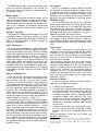
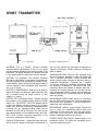
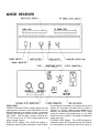
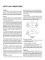
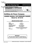
OPERATORS MANUAL
W25DR
W10BT
WL83
W10BT BODY-PACK TRANSMITTER
W25DR DIVERSITY RECEIVER
WL83 LAVALIER MICROPHONE
. . . ON ACQUIRING ONE OF THE FINEST WIRELESS MICROPHONE SYSTEMS AVAILABLE TODAY. DESIGNED FOR SIMPLE SETUP AND RELIABLE OPERATION, THIS SYSTEM SHOULD PROVIDE YEARS OF DEPENDABLE, TROUBLE-FREE SERVICE. WE STRONGLY URGE THAT YOU
READ THIS MANUAL; IT WILL SAVE YOU TIME AND EFFORT, AND ENSURE OPTIMUM SYSTEM
OPERATION.
TABLE OF CONTENTS
The Wireless Microphone . . . . . . . . . . . . . . . . . . . . . . . . . . . . . . . . . . . . . . . . . . . . . . . . . . . . . . . . .
Frequency Bands . . . . . . . . . . . . . . . . . . . . . . . . . . . . . . . . . . . . . . . . . . . . . . . . . . . . . . . . . . . . .
Diversity Reception . . . . . . . . . . . . . . . . . . . . . . . . . . . . . . . . . . . . . . . . . . . . . . . . . . . . . . . . . .
Multiple Miking . . . . . . . . . . . . . . . . . . . . . . . . . . . . . . . . . . . . . . . . . . . . . . . . . . . .
Directional Sensitivity . . . . . . . . . . . . . . . . . . . . . . . . . . . . . . . . . . . . . . . . . . . . . . . . . . . . . . .
Audio Performance . . . . . . . . . . . . . . . . . . . . . . . . . . . . . . . . . . . . . . . . . . . . . . . . . . . . . . . . . .
W ith the Transmitter Off . . . . . . . . . . . . . . . . . . . . . . . . . . . . . . . . . . . . . . . . . . . . . . . . . . . . .
On Feedback . . . . . . . . . . . . . . . . . . . . . . . . . . . . . . . . . . . . . . . . . . . . . . . . . . . . . . . . . . . . .
Transmitter Range . . . . . . . . . . . . . . . . . . . . . . . . . . . . . . . . . . . . . . . . . . . . . . . . . . . . . . . . . . . . .
System Power . . . . . . . . . . . . . . . . . . . . . . . . . . . . . . . . . . . . . . . . . . . . . . . . . . . . . . . . . . . . . . . . .
What Else is Needed . . . . . . . . . . . . . . . . . . . . . . . . . . . . . . . . . . . . . . . . . . . . . . . . . . . . . . . . . . .
W10BT Transmitter . . . . . . . . . . . . . . . . . . . . . . . . . . . . . . . . . . . . . . . . . . . . . . . . . . . . . . . . . . . . . . .
W25DR Receiver . . . . . . . . . . . . . . . . . . . . . . . . . . . . . . . . . . . . . . . . . . . . . . . . . . . . . . . . . . . . . . . . .
Setup and Connections . . . . . . . . . . . . . . . . . . . . . . . . . . . . . . . . . . . . . . . . . . . . . . . . . . . . . . . . . . . .
Unpacking . . . . . . . . . . . . . . . . . . . . . . . . . . . . . . . . . . . . . . . . . . . . . . . . . . . . . . . . . . . . . . . . . . .
Receiver . . . . . . . . . . . . . . . . . . . . . . . . . . . . . . . . . . . . . . . . . . . . . . . . . . . . . . . . . . . . . . . . . . . . . .
For Microphone Level Use . . . . . . . . . . . . . . . . . . . . . . . . . . . . . . . . . . . . . . . . . . . . . . . . . . . . .
For Line Level Use . . . . . . . . . . . . . . . . . . . . . . . . . . . . . . . . . . . . . . . . . . . . . . . . . . . . . . . . . . . .
Audio Output Connections . . . . . . . . . . . . . . . . . . . . . . . . . . . . . . . . . . . . . . . . . . . . . . . . . . . .
Transmitter . . . . . . . . . . . . . . . . . . . . . . . . . . . . . . . . . . . . . . . . . . . . . . . . . . . . . . . . . . . . . . . . . . .
Microphone Connections . . . . . . . . . . . . . . . . . . . . . . . . . . . . . . . . . . . . . . . . . . . . . . . . . . . . . .
Instrument Connections . . . . . . . . . . . . . . . . . . . . . . . . . . . . . . . . . . . . . . . . . . . . . . . . . . . . . .
Battery Check . . . . . . . . . . . . . . . . . . . . . . . . . . . . . . . . . . . . . . . . . . . . . . . . . . . . . . . . . . . . . . .
Polarity . . . . . . . . . . . . . . . . . . . . . . . . . . . . . . . . . . . . . . . . . . . . . . . . . . . . . . . . . . . . . . . . . . . . .
Setting Gain Levels . . . . . . . . . . . . . . . . . . . . . . . . . . . . . . . . . . . . . . . . . . . . . . . . . . . . . . . . . . . . . .
Transmitter Gain . . . . . . . . . . . . . . . . . . . . . . . . . . . . . . . . . . . . . . . . . . . . . . . . . . . . . . . . . . . . . . .
Sound Pressure Levels . . . . . . . . . . . . . . . . . . . . . . . . . . . . . . . . . . . . . . . . . . . . . . . . . . . . . . . .
Receiver Gain . . . . . . . . . . . . . . . . . . . . . . . . . . . . . . . . . . . . . . . . . . . . . . . . . . . . . . . . . . . . . . . . .
Audio Output Settings . . . . . . . . . . . . . . . . . . . . . . . . . . . . . . . . . . . . . . . . . . . . . . . . . . . . . . . . . .
Checklist/Operation . . . . . . . . . . . . . . . . . . . . . . . . . . . . . . . . . . . . . . . . . . . . . . . . . . . . . . . . . . . . . .
Specifications . . . . . . . . . . . . . . . . . . . . . . . . . . . . . . . . . . . . . . . . . . . . . . . . . . . . . . . . . . . . . . . . . . .
Antennas . . . . . . . . . . . . . . . . . . . . . . . . . . . . . . . . . . . . . . . . . . . . . . . . . . . . . . . . . . . . . . . . . . . . .
Transmitter . . . . . . . . . . . . . . . . . . . . . . . . . . . . . . . . . . . . . . . . . . . . . . . . . . . . . . . . . . . . . . . . . . . .
Receiver . . . . . . . . . . . . . . . . . . . . . . . . . . . . . . . . . . . . . . . . . . . . . . . . . . . . . . . . . . . . . . . . . . . .
Receiver Antenna Distance . . . . . . . . . . . . . . . . . . . . . . . . . . . . . . . . . . . . . . . . . . . . . . . . . . . .
Receiver-Transmitter Distance . . . . . . . . . . . . . . . . . . . . . . . . . . . . . . . . . . . . . . . . . . . . . . . . . . .
Receiver Antenna Mounting . . . . . . . . . . . . . . . . . . . . . . . . . . . . . . . . . . . . . . . . . . . . . . . . . . .
Batteries . . . . . . . . . . . . . . . . . . . . . . . . . . . . . . . . . . . . . . . . . . . . . . . . . . . . . . . . . . . . . . . . . . . . . .
Troubleshooting . . . . . . . . . . . . . . . . . . . . . . . . . . . . . . . . . . . . . . . . . . . . . . . . . . . . . . . . . . . . . . . . .
Accessories . . . . . . . . . . . . . . . . . . . . . . . . . . . . . . . . . . . . . . . . . . . . . . . . . . . . . . . . . . . . . . . . . . .
FCC Certification . . . . . . . . . . . . . . . . . . . . . . . . . . . . . . . . . . . . . . . . . . . . . . . . . . . . . . . . . . . . . . . . .
Warranty Service . . . . . . . . . . . . . . . . . . . . . . . . . . . . . . . . . . . . . . . . . . . . . . . . . . . . . . . . . . . . . . .
3
3
3
4
4
4
4
4
4
4
4
5
6
8
8
8
8
8
8
8
9
9
9
8
10
10
10
10
11
12
13
14
14
14
14
14
14
16
17
18
19
19
THE WIRELESS MICROPHONE
. . . what it is, what it does . . .
poles, causes your radio signal to drop to a low, noisy
level -sometimes disappearing completely. This is
multipath.
The wireless microphone is actually a system consisting of a microphone, a transmitter, and a receiver. The
microphone is an electroacoustic transducer-a device
which converts sound waves (voice, musical instruments, etc.) to electrical inpulses, which are sent to
the transmitter. The transmitter generates a radiofrequency carrier, modulates this carrier with the
microphone signals, and radiates this modulated RF
signal like a tiny radio station. The receiver is matched
to the transmitter frequency and picks up the transmitter
signal through its antenna. The receiver’s circuitry
detects the modulated RF signal and converts it to an
audio voltage for routing (through a microphone input) to
an audio mixer.
At this point, the wireless system acts like any
microphone input to a sound system. The figure below
shows the complete system, including that which is not
a part of the wireless microphone system.
Frequency Bands.....
Shure wireless transmitters and receivers are singlechannel, crystal-controlled units operating in the VHFFM band between 150 and 216 megahertz. A total of 15
frequencies, computer-selected for interference-free
operation, are readily available, and other frequencies
can be ordered on a special basis. This means that up to
12 systems can be operated in a single sound installation, simultaneously and without intermodulation problems.
Multipath is virtually a thing of the past with a unique
antenna/receiver system called DIVERSIPHASE™. The
two antennas supplied with the W25DR receiver are placed some distance apart, and the signals each receives
are compared at the receiver. The W25DR’s DIVERSIPHASE circuit monitors each antenna, and if the direct
and reflected signals appear to be creating an out-ofphase condition-and the inevitable signal dropout, the
receiver modifies the phase difference between the two
antennas until the two signals add in phase.
Diversity Reception.....
The most troublesome aspect of wireless microphone
operation can be a phenomenon known as multipath
transmission, or simply, multipath. This appears as a
signal “dropout,” with annoying static or complete
(although temporary) signal loss. It’s caused when the
direct signal and a reflected signal-bounced off walls,
ceiling, metallic objects, etc.-arrive at the receiver at
different times, literally out-of-phase, or when the signal
path is completely blocked.
You’ve probably experienced this phenomenon with
the FM radio in your car. A dropout location, most likely
caused by buildings, mountains, or even telephone
TYPICAL WIRELESS MICROPHONE SYSTEM
3
On Feedback.....
The use of a wireless microphone doesn’t eliminate
the possibility of annoying feedback. Feedback control
is generally achieved by careful placement of the
speakers relative to the microphone, minimum levels
necessary for the desired sound, good microphone
technique, and proper equalization of the sound system.
Transmitter Range.....
The FCC-required low power output of the transmitter
means that its distance from the receiver should be kept
as short as possible. Up to 150 meters (500 feet) should
be considered a maximum, although 300-meter
(1000-foot) or greater operation is often accomplished.
Reflections, obstacles and interference in a given installation will dictate the system’s limits.
Other wireless systems that claim greater distance
and flexibility in their operation neglect to state that
each installation must be considered separately. A wide
variance exists between best- and worst-case conditions.
System Power.....
The receiver operates from power supplied by a
separate ac power converter provided with the system.
In addition to 120-volt operation with the power converter, the receiver can be operated from any well-filtered
source of 13.5 Vdc at 200 mA. An optional 220-volt power
converter is also available.
The transmitter operates from any 9-volt alkaline
transistor-radio-type battery (Duracell MN1604 is recommended). Typical battery life is 8 hours. Inexpensive
carbon-zinc batteries are not recommended; their extremely short life-about an hour-restricts them to
emergency use only. If nickel-cadmium rechargeable
batteries are used, they must be 8.4-volt (not 7.2-volt)
types. The lower-voltage batteries will not provide proper
transmitter function,
What Else is Needed.....
In order to make this wireless microphone system
operational, the following is needed:
DIVERSIPHASE reception, plus close attention to the
simple but important instructions in this manual, will
help provide clean, clear wireless microphone operation
in almost any setting.
Multiple Miking.....
More than one wireless microphone system can be
used in one sound installation, but each must operate at
a different frequency. Shure’s complement of 15 standard transmitter-receiver frequencies is generally sufficient’ for any installation, but additional, special-order
frequencies can also be supplied for a nominal service
charge.
Directional Sensitivity.....
The transmitter radiates omnidirectionally, that is, approximately equally in all directions. However, the signal
is attenuated by bodies, walls, and other surrounding objects. The receiving antenna is similarly sensitive to
radiation in all directions.
Audio Performance.....
Three important characteristics of high-fidelity audio
performance are wide frequency response, low distortion and good signal-to-noise ratio. The Shure wireless
system uses high-quality FM circuitry for wide-range frequency response. Distortion is kept to a minimum
through the use of linear-phase IF filtering and highquality audio circuitry. A high signal-to-noise ratio and
wide dynamic range are necessary for noise-free, optimum performance. The Shure wireless uses complementary compression and expansion circuitry in the
transmitter and receiver (companding) as well as pre-and
de-emphasis to achieve a maximum S/N ratio of 98 dB
A-weighted.
With the Transmitter Off.....
When the wireless microphone transmitter is turned
off, the receiver can still receive transmissions from
other sources. However, since the Shure system
operates in the 150-216 MHz band, it’s not susceptible to
such irritations as radio wave skip, or CB or FM broadcast transmissions. The frequencies selected for use in
the Shure system are computer-selected for minimum interference, but it’s almost impossible to guarantee a
“clear channel” at any location or at any time. (For instance, care must be taken to avoid wireless microphone
operating frequencies that are within the bandwidth of
locally operating TV channels 7 through 13.)
If the wireless system is to be in a permanent location,
it should operate without interference until someone
else in the vicinity starts using that frequency. But if the
system is to be used in different locations (i.e., “on the
road”), occasional frequency conflicts are inevitable. In
any case, if the wireless microphone is not in use, the
audio mixer gain should be turned down just as with a
wired microphone. If the mixer controls are not accessible, turn the receiver off when the transmitter is not in
use to prevent unwanted signal pickup. If the system
must be left on and mixer controls are not accessible,
the transmitter should be left on to prevent outside interference pickup.
1. A battery for the transmitter.
2. A microphone for the transmitter -either one designed specifically for the wireless transmitter (such as
the Shure WL83), or most low-impedance
microphones (dynamic, ribbon or condenser) with a
microphone adapter cable (WA310).* But if the
wireless system is to be connected to the electrical
output of a musical instrument instead of a
microphone, a transmitter instrument cable (WA300)
must be used.
3. A receiver-to-mixer cable, with a female XLR connector on one end (for the receiver output) and a mating
connector for the mixer microphone input on the
other.
Optional accessories, useful but not required, are
described in this manual.
* IMPORTANT: Other microphones specified as being for wireless microphone use
are probably not wired for use in Shure wireless systems. Condenser microphones
with phantom-powered preamp circuits-Shure SM85, SM87, etc.-will not operate
with this transmitter.
4
W10BT TRANSMITTER
ANTENNA: This is a flexible, 1/4-wave vertically
polarized antenna approximately 30 cm (12 in.) in length
and permanently attached to the bottom surface of the
transmitter. For proper operation, the antenna must be
in the vertical position; it cannot be coiled or bundled.
the Low Gain position for high-output microphones or
musical instruments. Allows maximum modulation
without clipping.
MICROPHONE JACK: This is a 4-pin, miniature, male
Tini Q-G connector designed to mate with Switchcraft
TA4F or equivalent connectors. A built-in 20-kilohm load
resistor provides proper matching for dynamic, ribbon or
condenser microphones. Connector pin 2 supplies
+5-volt bias voltage for condenser microphone phantom powering. In addition to microphones with TA4F
connectors, Shure has available an adapter cable with a
standard XLR female connector for use with conventional microphones (WA310), and a musical instrument
adapter cable with a 1/4-inch phone plug on the equipment end (WA300).
BATTERY (not supplied): Only alkaline (Duracell
MN1604 or equivalent) or heavy-duty nickel-cadmium
(8.4-volt) transistor-radio-type batteries should be used.
A fresh alkaline battery should provide approximately 8
hours of operation, and a recharged nicad should provide 1-1/2 to 2 hours.
BATTERY COMPARTMENT: Slide the cover down to
expose the battery compartment. Make certain the battery is installed using the proper positive (+) and
negative (-) polarity.
MICROPHONE LEVEL Rotary Control: In conjunction
with the GAIN HI/LO switch, this control provides additional audio level adjustment. A small screwdriver is
supplied to make adjustments.
BATTERY TEST Push-Button Switch: Permits checking
the condition of the installed battery when the Power
switch is on. The BATTERY TEST LED Indicator will fail
to light if the battery is weak or dead (or if the Power
switch is off). Note that if the battery is tested periodically during use, an impending battery failure can be
detected: the LED will fail to light at 7.25 volts. At that
time, approximately 1 hour of alkaline battery life is left.
MICROPHONE ON/OFF Toggle Switch: Permits the
user to “mute” the microphone without turning the
transmitter off. This avoids the “pop” that may accompany power turn-on and turn-off, and generally prevents
pickup of unwanted signals by the receiver.
BELT CLIP: Permits convenient attachment to the
user’s belt, waistband or other clothing.
POWER ON/OFF Slide Switch: Applies power to the
transmitter circuitry. The switch is a low-profile type to
minimize accidental turn-off.
GAIN HI/LO Slide Switch: Selects the High Gain position to boost the signal of low-output microphones, or
5
W25DR RECEIVER
FRONT PANEL
POWER Push-Button Switch: Applies power from the
external power converter or other well-filtered 13.5 Vdc
(200 mA) sources to the receiver circuitry. An adjacent
POWER LED Indicator remains on while power is applied. (NOTE: With the power converter connected to a
115 Vac, 60 Hz source, 13.5 Vdc is always present at the
power converter output.)
tion is shown by illumination of the green portion of the
display, with occasional excursions into the yellow. If
frequent or constant yellow or red indications are
observed, the transmitter MICROPHONE LEVEL control
should be lowered (counterclockwise), or the GAIN
switch set to the Lo position. The display is calibrated in
volume units (VU).
RF SIGNAL LEVEL Display: This 10-LED bar display indicates the relative RF level received from the transmitter. Red indicates an insufficient signal level; yellow in-
AUDIO LEVEL Display: This 10-LED bar display indicates the relative system modulation. Normal opera6
dropout-free performance in diversity operation. Additional coaxial cables (WA280) can be connected for
greater total antenna separation if necessary.
dicates a marginal signal condition; and green indicates
an acceptable level. Full-scale indication is desirable for
best signal-to-noise performance, but changes
throughout the green portion of the display will still
result in good operation. The receiver contains a squelch
circuit to eliminate unwanted signals or noise in the
absence of wireless transmitter signals. The squelch circuit is not user-adjustable; it is preset to an optimum
threshold setting of 1.0 µV, minimizing setting errors and
difficulties in returning the squelch to its original setting.
FUSE 1/2A: This is a 0.5-ampere, 250-volt, 3AG-type,
fast-blow fuse that protects the power supply from excessive current. It should be replaced only with a fuse of
identical size and value (Littelfuse 312.500 or
equivalent).
MICROPHONE OUTPUT LEVEL Rotary Control: This
control determines the signal level at the OUTPUT Connector when the MlC/LlNE Switch is in the Mic position.
Using this control, the signal level can be matched to
that of a conventional wired microphone.
LEVEL Rotary Control: Adjusts the signal level at the
AUXILIARY OUTPUT Jack. The control operates in all IMPEDANCE Switch positions.
MlC/LlNE Slide Switch: In the Line position, the
nominal (100% modulation) output level is not adjustable at the receiver and is used to drive 600-ohm
lines to mixers, amplifiers, etc. In the Mic position, the
output level is adjustable from -55 dBm to -16 dBm
using the MICROPHONE OUTPUT LEVEL Control. This
position is used to drive 150-ohm microphone-level lines.
IMPEDANCE Rocker Switch: A three-position switch
for selecting the proper source impedance to the AUXILIARY OUTPUT Jack. In general, the 8-Ohm position is
for monitor headsets, 600 Ohms for monitor headsets or
600-ohm line devices, and the 10K (10 kilohms) for highimpedance devices such as effects units and guitar
amplifiers.
POWER 13.5 VDC NEGATIVE GROUND Coaxial
Jack: This connector accepts power from the supplied
power converter, or from any well-filtered 13.5 Vdc (200
mA) supply.
REAR PANEL
ANTENNA A, B UHF-Type Connectors: Provide for connection to the two 5/8-wave vertical antennas supplied
with the W25DR. A 7.6-meter (25-foot) coaxial cable (supplied) is installed between one antenna and the receiver
connector to remotely locate the antenna for optimum
OUTPUT 3-Pin XLR Connector: Provides balanced output for connection to the audio mixer or amplifier, depending on the MlC/LlNE Switch position.
7
SETUP AND CONNECTIONS
connecting cable and connect between the W25DR OUTPUT Connector and the mixer or amplifier microphonelevel input. Make certain the receiver MlC/LlNE Switch is
in the MIC position. Adjust the levels as described under
Level Adjustment.
UNPACKING
Unpack all units and parts of the Wireless Microphone
System. If possible, retain packaging in the event of
returning a unit for repair. Check all boxes and inner
packaging; if any damage or shortage is discovered,
refer to the Warranty Service section of this manual.
For Line Level Use
Obtain an XLR-phone plug unbalanced audio connecting cable and connect it between the W25DR OUTPUT
Connector and the mixer or amplifier line input jack (see
Figure 1). Make certain the MlC/LlNE Switch is in the
LINE position. No adjustments are necessary.
RECEIVER
Place the W25DR receiver in its operating location and
connect the supplied power converter to the rear panel
POWER Jack. Connect the power converter to a 105 to
125 Vac, 60 Hz power source.
Assemble the two 5/8-wave whip antennas by screwing the three sections of each antenna together. IMPORTANT: Do not use either antenna with one or two sections; all three sections must be connected for proper
operation. Attach the right-angle UHF adapter to one
ANTENNA connector. Attach one antenna to the
upward-facing end of the UHF adapter. Connect the supplied 7.6m (25 ft) coaxial cable to the other ANTENNA input. NOTE: For more information on antenna spacing
for optimum reception, refer to the Antenna section of
this manual.
Connect the second antenna to the other end of the
coaxial cable. The L-bracket and three screws supplied
with the receiver permit the second antenna to be
mounted on a wall or other vertical surface. After the
bracket is fastened to the surface with the screws, insert
the antenna base in the circular cutout of the bracket
and tighten the hex nut and washer to secure the antenna.
The coaxial cable allows distance of 7.6m (25 ft) for
optimum diversity operation. A second cable can be obtained (WA280) to provide greater antenna separation of
15.2m (50 ft) for use in extremely difficult operational environments. Note that the insulated hook at the top of
the antenna can be used to suspend the antenna from
any convenient non-metallic object (hook, bracket, rope,
etc.).
IMPORTANT: Make certain both antennas are within
the line-of-sight of the transmitter’s operating area. This
will facilitate the best use of the receiver’s DIVERSIPHASE™ circuit for clean, clear, dropout-free operation.
If desired, the receiver can be installed in a single
(WA220) or double (WA230) rack panel kit for mounting in
a standard 19-inch audio equipment rack. Note that
receiver rack-mounting requires remote location of both
antennas.
CABLE WIRING
FIGURE 1
Audio Output Connections
The front-panel 1/4-inch phone jack permits feeding
the W25DR output signal to:
• An 8-ohm headphone (stereo or mono)
• A 600-ohm headphone or line input
• A 10-kilohm input to a guitar amplifier or the auxiliary
input of an amplifier, mixer or tape recorder.
The IMPEDANCE Switch adjacent to the phone jack
selects the desired impedance, and the adjacent LEVEL
Control sets the appropriate level for the input to be used.
TRANSMITTER
With the transmitter POWER ON/OFF Switch in the
OFF position, slide the battery compartment access
cover down and off the transmitter case. Insert a new
9-volt transistor-radio-type battery (Duracell MN1604 or
equivalent) in the compartment. Observe the proper
polarity: the large (negative) terminal in the large channel and the small (positive) terminal in the small channel.
For Microphone Level Use
Obtain an XLR-type balanced low-impedance audio
8
Operation with a full charged, heavy-duty, 8.4-volt nickelcadmium rechargeable battery is also permissible. IMPORTANT: Do not use a “conventional” g-volt-sized
nickel-cadmium battery; its 7.2-volt output will operate
the transmitter for about 15 minutes. Carbon-zinc batteries will also result in diminished operating life (about
1 hour).
Microphone Connections
The Shure WL83 lavalier condenser microphone or
similar microphones with identical wiring and a Switchcraft TA4F type connector can be plugged directly into
the transmitter microphone jack. The WL83 will operate
using the transmitter’s regulated +5 Vdc available on
pin 2 (see Figure 2). Self-powered (battery) condenser
microphones can be used with the transmitter only if
they can be operated in an unbalanced mode (one side
grounded). Other non-self-powered condenser
microphones may require special wiring; contact
Shure’s Service Department for further information.
Phantom-powered condenser microphones will not
operate with the W10BT.
A high- or low-impedance dynamic or ribbon
microphone with pin 2 output can be directly connected
to the transmitter using the supplied WA310 microphone
adapter cable. The cable has a 3-socket XLR connector
on the microphone end and a Switchcraft TA4F connector on the transmitter end, and is wired for unbalanced
low-impedance operation only (see Figure 2). Shure highimpedance microphones are not wired to operate with
the transmitter. If a Shure high-impedance microphone
must be used, pins 2 and 3 should be reversed (by
qualified service personnel). Using a low-output, low
impedance dynamic lavalier microphone such as
Shure’s SM11 may raise the mixer input gain appreciably, which in turn may result in an increase in
noise and signal “pumping.”
TRANSMITTER CONNECTIONS AND
ACCESSORY WIRING
FIGURE 2
Battery Check
Turn the transmitter power on and depress the BATTERY TEST Switch. The adjacent LED should light, indicating adequate transmitter input voltage. If the LED
does not light, the alkaline battery voltage has dropped
below 7.25 volts and the battery should be replaced or
recharged (nicad only).
If the battery is tested periodically, the failure of the
LED to light indicates approximately one hour of battery
life left (alkaline only).
Polarity
With the Shure WL83 or a Shure low- or highimpedance XLR-connector microphone connected
through a WA310 cable, positive pressure on the
microphone diaphragm results in positive voltage on pin
2 with respect to pin 3 of the receiver OUTPUT connector, and positive voltage on the tip of the AUX OUTPUT
connector (8-ohm and 10-kilohm positions) or negative
voltage on the tip (600-ohm position). Negative voltage
applied to the tip of a WA300 cable will also result in the
same output polarities.
Instrument Connections
To connect the transmitter to a guitar or other musical
instrument pickup, obtain an instrument adapter cable
such as Shure’s WA300. This cable has a 1/4-inch phone
plug on one end and a Switchcraft TA4F on the other
(see Figure 2), and should function normally with any
high-impedance instrument pickup.
9
SETTING GAIN LEVELS
With the system in place and connected, all units can
now be turned on and the levels set to their optimum
positions.
TRANSMITTER
Place the POWER Switch of the W25DR receiver in the
ON position. The red POWER LED will light.
Turn the transmitter POWER ON/OFF Switch on.
Observe the receiver RF SIGNAL LEVEL display: one of
the green LED segments should light, indicating adequate RF signal strength for good transmission. A
yellow LED indication means less than optimum signal
transmission and/or reception, and a red LED indicates
less than satisfactory operation.
Turn the transmitter MIC ON/OFF Switch to the ON
position. With a microphone connected to the transmitter, the receiver AUDIO LEVEL display will now respond
to varying sound levels.
Set the transmitter GAIN switch as dictated by the
type of input: Hi for low-impedance microphones; LO
for high-impedance microphones and instrument
pickups.
HIGH SPL GAIN ADJUSTMENT
FIGURE 4
Low. Low SPL applications such as soft-spoken individuals or conditions where the microphone must be at
a greater-than-normal distance from the sound source,
may require an increase in the transmitter gain setting.
To correct for a low-level condition, turn the MIC LEVEL
Control up (clockwise; see Figure 5) until a proper (-7 to
0) LED reading is obtained.
Sound Pressure Levels
Normal. The transmitter MIC LEVEL Control has been
factory-set to provide optimum audio modulation at the
receiver, as indicated by LED illumination in the -7 to 0
range (see Figure 3). Readings in this area will yield the
highest dynamic range without overload and resulting
distortion.
AUDIO LEVEL DISPLAY
FIGURE 3
High. For high sound pressure level (SPL) applications
such as loud singing or musical instruments, the preset
transmitter level may be too high. To avoid this overload
and potential distortion condition, use the supplied
screwdriver to turn the transmitter MIC LEVEL Control
down (counterclockwise; see Figure 4). This adjustment
should be made under the expected operating conditions, that is, with the high SPL singer or musical instrument in use at the microphone. Turn the control down
until the optimum (-7 to 0) readings are obtained.
LOW SPL GAIN ADJUSTMENT
FIGURE 5
RECEIVER
The rear-panel receiver OUTPUT can be adjusted using
the MICROPHONE OUTPUT LEVEL Control. In this way,
the wireless system output can be made identical to that
of a conventional wired microphone, avoiding extreme
10
AUDIO OUTPUT SETTINGS
If the receiver output is to be fed to headphones,
600-ohm line devices, effects units or guitar amplifiers
using the front-panel AUXILIARY OUTPUT Jack, set the
3-position IMPEDANCE Switch for the type of equipment
to be used. Then rotate the LEVEL Control for the
desired signal level as monitored on the headphones or
as observed in the following equipment.
differences in input level settings. Turning the
MICROPHONE OUTPUT LEVEL Control counterclockwise decreases the output level, and turning it
clockwise increases the output.
Note that the control only functions when the
MlC/LlNE Switch is in the MIC position. With the switch
in the LINE position, the resulting line-level signal is at a
fixed level.
11
CHECKLIST/OPERATION
In most cases, the problem of weak RF signal strength
is also indicated by audible evidence: signal dropout,
either continuous or intermittent, or noisy, distorted
operation. The condition is generally caused by poor
antenna location, RF signal blocking, or operation
beyond the system capability. Refer to the
Troubleshooting section for remedies.
Normal operation is shown by illumination of a green
LED on the RF SIGNAL LEVEL display (see Figure 6). Optimum operation means one of the three top LEDs (8, 9,
10) may be lit. Weak signals and inadequate operation
are evidenced by illumination of the LEDs numbered 1
through 4.
CHECKLIST
The following checklist shows the status of your
wireless microphone system at this point. If the following steps have been performed and the expected result
obtained, the system can be put in operation.
c Is the receiver properly located?
c Is the power converter connected to the receiver? Is
ac power present?
c Are both antennas connected to the receiver?
c Is the receiver connected to the rest of the sound
system?
c Is a fresh battery installed in the transmitter?
c Is a microphone of the proper impedance and wiring
being used?
c Is the microphone or instrument connected to the
transmitter?
c Has the transmitter gain been set properly?
c Have the transmitter and transmitter antenna been
properly positioned?
c Is the receiver output level properly set?
c Is the audio output (headphones, effects, etc.) connected and properly set?
RF LEVELS
FIGURE 6
OPERATION
1. Turn on the transmitter and receiver POWER
Switches.
2. Make sure the transmitter MIC ON/OFF Switch is on.
3. Talk into the microphone (or play the connected
musical instrument) and observe the receiver
display for proper audio and RF indications.
4. Continue talking or playing and move around the
performing area. In each area, observe the receiver
displays and make sure the RF signal strength is
adequate.
Feedback-the annoying howl or squeal heard in the
sound system- is as much a problem in wireless
microphones as in wired mics. Checking microphone
operation throughout the performing area will probably
uncover any locations that are prone to audio feedback.
If the problem cannot be solved by a slight lowering of
the receiver output level or the associated amplifier gain,
relocation of the speakers or possibly professional
equalization of the sound system is recommended.
IMPORTANT
Every wireless microphone installation is a unique
situation, and can present a variety of problems.
Never attempt a live performance without a
“walkthrough” first. And if major changes (furniture, scenery, etc.) were made since the
walkthrough, check the wireless microphone
operation again.
12
SPECIFICATIONS
600 ohms . . . . . . . . . . . 40 mW maximum
10 kilohms . . . . . . . . . . . . . . . 0.2 mW maximum
Antenna Input Impedance
50 ohms nominal
Antenna
5/8 wavelength whip, UHF connector, length: 991 mm
(39 in.) (150 to 176 MHz); 762 mm (30 in.) (176 to 216
MHz)
Power
13.5 Vdc nominal (negative ground); 200 mA external
power converter supplied
Dimensions
88.9 mm (incl. feet) x 209 mm W x 211 mm D (3-1/2 in. x
8-1/4 in. x 8-5/16 in. ) (depth is 238 mm-9-3/8 in. including front-panel controls and power connector
clip)
Weight
1.97 kilograms (4 lb 5-1/2 oz)
SYSTEM
RF Carrier Frequency
150 to 216 MHz (15 frequencies between 167.875 and
213.8 MHz offered; others available)
Frequency Stability
0.005%, Crystal-Controlled
Ultimate Quieting (ref. 12 kHz deviation)
>90 dB at 30m (100 ft); 60 dB, line-of-sight at 402m
(1/4 mi.)
Modulation
± 12 kHz deviation compressor-expander system with
pre- and de-emphasis
Distortion (ref. 12 kHz deviation)
Less than 0.5% THD, 100 to 15,000 Hz; 0.3% at 1 kHz
typical
Dynamic Range
98 dB A-weighted
92 dB unweighted
Audio Frequency Response
50 to 15,000 Hz, ± 1 dB
Audio Polarity
Positive pressure on microphone diaphragm results
in positive voltage on pin 2 with respect to pin 3 of
OUTPUT connector, and positive voltage on tip of
AUX OUTPUT connector (&ohm and 10-kilohm positions) or negative voltage on tip (600-ohm position).
Negative voltage applied to tip of WA300 cable
results in same output polarities.
Temperature Range
Receiver . . . . . . . . . . -18° to 54°C (0° to 130°F)
Transmitter (alkaline batt.) . 0° to 38°C (32° to 100oF)
Transmitter (mercury batt.) . 4° to 54°C (40° to 130°F)
Transmitter (carbon-zinc) . . . 7° to 32°C (45° to 90oF)
Certification
Type-accepted under FCC Parts 90 and 74
(FCC ID DD48NJW25DR)
TRANSMITTER
RF Power Output
50 mW maximum; 30 mW typical
Modulation
54F3 ± 12 kHz deviation, 50 µsec pre-emphasis
Modulation Limiter
Internal compressor
Input Impedance
Actual: 16k (20k dc), pin 4 wired to pin 3 for WL83
microphone; 91k, pin 4 open for microphone or instrument pickup
Gain Switch
High position . . . . . . 0.0065 Vrms required for
100% modulation
Low position . . . . . . . . . 0.065 Vrms required for
100% modulation
Gain Adjustment Range
Low Position . . . . . . . . . . . . . . . . . . . . . . . . 20 dB
High Position . . . . . . . . . . . . . . . . . . . . . . . . 30 dB
Antenna
Attached, 305 mm (12 in.), omnidirectional, flexible
wire
Power
Battery Type . . . . . . 9 - v o l t a l k a l i n e ( N E D A
1604A); 8.4-volt nicad optional
Battery Life . . . . . . . . . . 6 to 8 hours typical
(alkaline); 1.5 to 2 hours
typical (8.4-volt nicad; per
charge)
Current Drain . . . . 35 mA typical
Dimensions
102 mm H x 69.8 mm W x 25.4 mm D (4 in. x 2-3/4 in. x 1
in.) (not including antenna, controls and belt clip)
Weight
113 grams (4 oz); 170 grams (6 oz) with battery
RECEIVER
RF Sensitivity
Less than 0.5 µV for 12 dB SINAD
Image Rejection
At least 75 dB
Spurious Rejection
At least 80 dB
Squelch Quieting
125 dB
Squelch Threshold
Internally preset to 1.0 µV
Mic/Line Output
Line . . . . . . . . . . . . 600 ohms, + 13.5 dB maximum
Mic . . . . . . . . . . . . 200 ohms, - 10 dB maximum (mic
level adjustable; -60 dB minimum)
Audio Output
8 ohms . . . . . . . . . . . . . . . . 75 mW maximum
13
ANTENNAS
TRANSMITTER
The transmitter antenna is a permanently attached,
flexible wire, 1/4-wave antenna. It has an omnidirectional
transmission pattern (equally effective in all directions)
and is designed to operate in a vertically polarized mode.
This means that the antenna should hang downward during operation; coiling or wadding it to minimize visibility
will reduce the system’s operating distance.
RECEIVER
The receiver antennas are three-section, 5/8-wave
whip antennas approximately 762 mm (30 in.) for 176 to
216 MHz operating frequencies, or 991 mm (39 in.) for 150
to 176 MHz. Like the transmitter antenna, the receiver
antennas have an omnidirectional pickup pattern and
are vertically polarized. Vertical mounting of both antennas is a requirement for optimum pickup.
The receiver antenna’s three sections must be joined
for optimum reception. One or two antenna sections will
result in reduced distance capability.
The receiver antennas are supplied with one rightangle UHF adapter for connecting one antenna to the
receiver, a 7.6m (25 ft) coaxial cable (WA280) with UHF
connectors for attaching the remotely located antenna
to the receiver, and a wall-mount bracket (WA260) with
hardware for mounting the remote antenna to a wall,
cabinet, etc.
Receiver Antenna Distance
For optimum performance of the DIVERSIPHASE™
system, proper antenna spacing is extremely important.
NEVER mount both antennas directly to the receiver
connectors. A minimum of 1.8m (6 ft) between antennas
is required for effective diversity reception (see Figure 7).
The 7.6m (25 ft) coaxial cable supplied with the antennas will provide “optimum” spacing between antennas
of 6.1-7.6m (20-25 ft) under ideal conditions. This, of
course, means little or no interference or reflections and
constant line-of-sight transmission.
Unfortunately, the real world is not free of these problems, and some applications may require greater antenna spacing for good diversity reception. An additional
7.6m (25 ft) coaxial cable (WA280) will provide 15.2m (50
ft) spacing and decreased problems. If greater lengths
are needed, the use of heavy-duty coaxial cable (Belden
8214 or equivalent) can be used for a maximum of 30m
(100 ft).
ANTENNA SPACING
FIGURE 7
•
•
•
Keep the transmitter to receiver antenna distance as
short as possible. As the distance increases, the
transmitted signal is weaker (see Figure 8).
Make certain the signal path between the transmitter
and the receiver antennas is unobstructed. The
transmitter wearer should be able to visually locate
at least one receiver antenna at any time (see Figure
9).
Try to avoid operating the system through or around
walls, ceilings, metal objects, etc. The usual result is
reduced range and performance, and the signal
reflections off metal obstructions will not only cause
reduced signal, but will introduce the problem of
multipath distortion (see Figure 10).
Receiver Antenna Mounting
The remotely located receiver antenna can be
mounted in a variety of locations and using a variety of
mounting methods. The supplied wall mount bracket
RECEIVER-TRANSMITTER DISTANCE
Observing the following rules regarding transmitter to
receiver antenna distance will yield the best results
possible.
14
(WA260) permits mounting the antenna to a wall, scenery
flat, or top of file cabinet (never the side). The insulated
hook at the end of the antenna allows it to be hung from
any nonmetallic rope or other line. (IMPORTANT: The
antenna must not be mounted on or next to metal
beams, metal-studded walls, equipment racks, etc., nor
hung from wire cables; this can result in detuning the
antenna and losing as much as 20 to 30 dB in RF signal
strength.)
The insulated base of the antenna can be attached to
any material including metal. The threaded portion of
the antenna (where the coaxial cable attaches) is a
neutral (ground-independent) point. A standard taperedhandle microphone swivel adapter (Shure A25B or
equivalent) allows the antenna to be mounted on a
microphone stand.
TRANSMITTER-RECEIVER DISTANCE
FIGURE 8
LINE-OF-SIGHT TRANSMISSION
FIGURE 9
ANTENNA PLACEMENT
FIGURE 11
OBSTRUCTION EFFECTS
FIGURE 10
15
BATTERIES
Careful transmitter battery selection, installation, use
and care will help avoid problems in wireless
microphone use. The most dependable, long-lived batteries at this time are the manganese-alkaline, or
alkaline, types. In addition to offering the longest expected operating life, they are commonly available.
One small word of caution about alkaline batteries:
they are not all the same size. Make certain the battery
you buy will make contact inside the battery compart-
The battery should be removed if the transmitter
malfunctions, or if it is to be stored for a long period.
Most batteries have a protective jacket, but partly or
completely exhausted batteries are more prone to
leakage.
Do not attempt to recharge replaceable (primary) batteries using “chargers”, heat or other methods. This may
cause leakage or explosion. Do not disassemble batteries or dispose of them in fire.
ment.
Nickel-cadmium (nicad) batteries can save money
through their rechargeability, but the tradeoff is in
shorter expected life per charge. In addition, forgetting
to recharge can be disastrous.
Another major consideration in nicads is that of
operating voltage. The “heavy-duty” 8.4-volt nicads are
satisfactory for transmitter use, but the “9-volt-size”
nicads commonly found in stores are only 7.2 volts and
will not provide satisfactory wireless performance.
Mercury batteries in the “9-volt-size” are also actually
8.4 volts. However, their discharge characteristics are
such that they will yield between 10 and 15 hours of
operation with the transmitter.
Carbon-zinc batteries are the least useful for transmitter operation. Their low cost is more than offset by their
extremely short operating and shelf life. Although the
“heavy-duty” (HD) carbon-zinc types offer better lowtemperature performance and service capacity at
moderate to high current drain, they will not offer appreciably better transmitter performance than standard
carbon-zinc batteries.
Although battery operation is inhibited at low
temperatures, storing batteries at low temperatures will
increase their shelf life. They should be sealed in bags
and, when ready for use, allow to warm up to room
temperature (never heated!). Cold-stored batteries
should be used as soon as possible after bringing to
room temperature.
Battery life is shortened by high-temperature storage
such as on amplifiers or in vehicles exposed to direct
sunlight.
MANUFACTURER
BATTERY TYPE
Alkaline
& NO.
VOLTS
Bright Star 7590
4° to 54°C
0° to 38°C
(32° to 100°F) (40° to 130° F)
Shelf Life (room
temperature; to
80% of capacity)
30 months
30 months
NEDA 1604A
Panasonic 6AM6
Radio Shack
23-553
Ray-O-Vac
A1604
U.S. Military
BA3090
Varta 4022
Burgess H146X
Mercury
Duracell TR146X
Eveready E146X
NEDA 1604M
Panasonic TR146
U.S. Military
BA1090/U
Nickel-Cadmium
SAFT PS-9
8.4
Varta TR7/8
Carbon-Zinc
Duracell M1604
Eveready
Ray-O-Vac
1-1/2 to 2 hours
per charge
9.0
1 hour
9.0
1 hour
216
1604
Radio Shack
23-464
Carbon-Zinc
Duty)
Duracell
M1604HD
Ray-O-Vac
23-583
Nicad
7° to 32°C
-20° to 45°C
(45° to 90° F) (-4° to 113°F)
6 to 12
months
10 to 15 hours
IEC 6LF22
D1604
Radio Shack
Temperature
8.4
Eveready 522
Eveready 1222
CarbonZinc
6 to 7 hours
ESB A1604
RECOMMENDED RANGES
Mercury
9.0
Duracell MN1604
(Heavy
Alkaline
EXPECTED LIFE
10 to 80 days
16
TROUBLESHOOTING
If you encounter any problems in the operation of your Shure Wireless Microphone System, first make certain
you’ve followed the ABC’s of proper wireless microphone operation:
Make certain the transmitter antenna is dangling vertically. Make certain the receiver antennas are
properly connected, located and mounted.
Make certain the transmitter battery is fresh and of the right type. And while you’re at it, make cerBattery tain the receiver power converter is connected to a functioning power source.
All receiver and transmitter controls should be properly set for the desired operation. Recheck all
Controls settings for correct system setup.
If you still have a problem, follow the advice below. If you’re unable to solve the problem, contact your dealer or
Shure’s Service Department.
Antennas -
PROBLEM
SOLUTION
Movement around the performing area produces
intermittent “swooshing” sound or complete loss of
signal (dropout).
Make certain both antennas are properly connected,
mounted and positioned for optimum reception. Minimize transmitter-to-receiver distance.
Audio signal sounds distorted at medium to high
input levels.
Reduce transmitter audio gain.
Receiver picks up other (interfering) radio signals.
Make certain transmitter is turned on. If problem persists with transmitter on, it may be necessary to
change system operating frequency. (Another
transmitter, possibly a VHF-TV transmitter, may be
operating at the same frequency.)
Audio signal contains undesirable whistling or
chirping sounds, or sounds garbled.
Two transmitters may be operating simultaneously
on the same frequency. Turn one transmitter off. If
problem persists, may be caused by other radio
signals (see above).
Audio signal contains undesirable hissing sounds.
Transmitter and/or receiver gain may require
increase (setting is too low).
One wireless microphone produces a lower output
than other wireless microphones in the same sound
system.
Movement around the performing area produces an
undesirable squeal or howl (feedback).
Relocate the speakers. Reduce the receiver and/or
and/or sound system gain. (Professional equalization
may be required.)
Maximum operating distance (transmitter to receiver
antenna) seems less than when system was new.
Transmitter antenna may require replacement.
Receiver antennas may require relocation.
Short transmitter battery life.
Make certain replaceable batteries are alkaline
(Duracell MN1604 or equivalent). Make certain
rechargeable batteries (nicads) are 8.4-volt types.
Receiver not functioning.
Make certain receiver power converter is connected
to functioning ac source.
Make certain rear-panel 0.5A, 250V, 3AG fuse is not
blown.
REMEMBER: Many apparent problems are due to improper setup and operation. Make certain you have followed
instructions carefully before contacting Shure for service.
17
ACCESSORIES
The following Shure Wireless System accessories are
available through your Shure dealer. (Replacement parts
can be ordered from Shure’s Service Department; information is available from Shure’s Service Department.)
MODEL WA280 COAXIAL ANTENNA CABLE - Identical
to the coaxial antenna cable supplied with the W25DR
receiver, the WA280 can be used as a replacement or to
extend the diversity antenna an additional 7.6m (25 ft).
MODEL WL83 LAVALIER CONDENSER MICROPHONE
- This is a tiny electret condenser microphone designed for high-quality sound reproduction in broadcasting,
film and sound reinforcement applications. The WL83
plugs directly into the W10BT transmitter, and is supplied with a variety of mounting options.
MODEL WA300 INSTRUMENT CABLE - This is a 1.2m (4
ft), single-conductor, shielded cable with a 1/4-inch
phone plug on one end and a Switchcraft TA4F on the
other. It is used for connecting the W10BT transmitter to
a guitar or other musical instrument pickup.
MODEL WA220 SINGLE RECEIVER RACK MOUNT KIT
- This kit consists of brackets and hardware for mounting a W25DR receiver in a standard 19-in (483 mm) audio
equipment rack.
MODEL WA230 DOUBLE RECEIVER RACK MOUNT KIT
- This kit consists of brackets and hardware for mounting two W25DR receivers in a standard 19-inch (483 mm)
audio equipment rack.
MODEL WA310 MICROPHONE CABLE - A 1.2m (4 ft),
single-conductor, shielded cable with a 3-socket (female)
XLR connector on one end and a Switchcraft TA4F on
the other. The WA310 is designed to connect the W10BT
to a high- or low-impedance dynamic or condenser
microphone for unbalanced operation.
MODEL WA320 AC POWER CONVERTER - This is a
replacement for the 120 Vac power converter supplied
with the W25DR receiver.
MODEL WA250 5/8-WAVE WHIP ANTENNA - This
3-section whip antenna is a replacement for the antennas supplied with the W25DR receiver. It comes with a
right-angle UHF adapter.
MODEL WA330 MICROPHONE CONNECTOR - This
TA4F miniature connector permits microphones such as
the Shure SM10A or SM98 to be connected directly to the
W10BT transmitter.
MODEL WA260 ANTENNA WALL-MOUNT BRACKET This bracket is a replacement for the 5/8-wave whip
antenna bracket supplied with the W25DR receiver. It
comes with mounting hardware.
MODEL WA350 AC POWER CONVERTER - Similar to
the WA320, this power converter permits operation at
220 to 240 Vac.
18
FCC CERTIFICATION
quency. Shure strongly urges the user to contact the appropriate telecommunications authority before choosing and ordering frequencies other than factory-preset
frequencies. This recommendation applies to both
original equipment purchase and subsequent frequency
modification by Shure.
The Shure Model W10BT transmitter is Type-Accepted
under Federal Communications Commission Parts 90
and 74. The Shure Model W25DR receiver is TypeAccepted under FCC Part 15. Licensing of Shure
wireless microphone equipment is the user’s responsibility, and licensability depends on the user’s
classification and application, and on the selected fre-
WARRANTY SERVICE
If your Shure wireless microphone equipment should
require servicing under the Shure warranty, please contact:
Shure Brothers Inc.
Attention: Service Department
222 Hartrey Avenue
Evanston, Illinois 60202-3696 U.S.A.
Telephone: (312) 866-5730
If you are requested to return the equipment by
Shure’s Service Department, package the unit (with all
information requested) as follows: Check to see that
all parts are present and in place. If the original carton is
not available, place the unit in a strong shipping carton
at least 13 mm (6 in.) larger in all three dimensions than
the unit. Fill the surrounding space with a resilient packing material such as shredded paper, excelsior,
Styrofoam, etc. Seal the carton with gummed paper tape,
tie it with a strong cord, and ship it prepaid to the Shure
Service Department.
It is extremely important that the packaged unit be
well-packed and fully insured. Damage claims are subject to settlement between the shipper and the carrier,
and this can delay repair and return of the unit.
Shure reserves the right to make design changes and
product improvements without assuming any obligation
to install these changes or improvements on any
previously manufactured products. Shure also reserves
the right to ship new and/or improved products which are
similar to the form, fit and function of the originally
ordered products.
All claims of defects or shortage should be directed to
the above address. Please furnish model number,
operating frequency, and date, place and proof of purchase (such as a copy of the sales receipt) to establish
warranty. Your letter should include all pertinent details
including applicable model or part numbers and a brief
description of the problem. Do not return any units or
parts to Shure unless requested to do so by Shure’s Service Department. Any returned items must have prior
authorization. Unauthorized returns are delayed in
handling; these delays can be avoided by contacting
Shure in advance and furnishing the necessary information.
19
222 HARTREY AVENUE, EVANSTON, ILLINOIS 60202-3696 U.S.A. • TELEPHONE: (312) 866-2200 • CABLE: SHUREMlCRO
Copyright 1986, Shure Brothers Inc.
27A2315 (FL)
Printed in U.S.A.