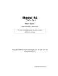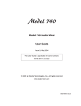
1
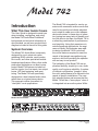
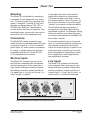
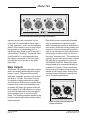
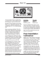
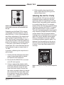
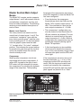
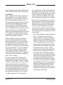
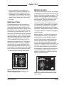
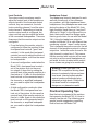
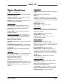
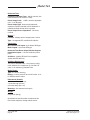
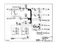
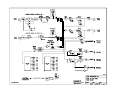
Model 742
Model 742 Audio Mixer
User Guide
Issue 2, May 2005
This User Guide is applicable for serial numbers:
M742-00160 and later*
* For units with serial numbers 00160-00169 refer to the
Technical Notes section of this user guide
© 2005 by Studio Technologies, Inc., all rights reserved
www.studio-tech.com
50265-0505, Issue 2
This page intentionally left blank.
Model 742
Table of Contents
Introduction ................................................................... 5
System Features ........................................................... 6
Configuration Review .................................................... 8
Installation ..................................................................... 10
Post-Installation Calibration .......................................... 15
Operation ...................................................................... 17
Technical Notes ............................................................. 23
Specifications ................................................................ 27
Block Diagrams
Model 742 User Guide
Studio Technologies, Inc.
Issue 2, May 2005
Page 3
Model 742
This page intentionally left blank.
Issue 2, May 2005
Page 4
Model 742 User Guide
Studio Technologies, Inc.
Model 742
Model 742
Introduction
What This User Guide Covers
This User Guide is designed to assist you
when installing, configuring, and using
the Model 742 Audio Mixer. Additional
background and technical information is
also provided, as well as a product block
diagram included at the end of this guide.
System Overview
The Model 742 Audio Mixer is expressly
designed for use in electronic-newsgathering (ENG) vehicles, small production trucks, and other specialized mobile
broadcast applications. Many other audio
production applications can also be supported. Model 742 features include four
mic/line inputs, four line inputs, two output
buses, LED level metering, and monitoring. The Model 742 was specifically
designed as a dual-channel audio mixer,
rather than as a typical stereo device.
This approach makes it excellent for
“dual-path” on-air applications.
The Model 742 is targeted for use by operators with numerous audio sources that
need to be quickly and reliably adjusted
and routed to create one or two independent audio mixes. In these days of operators having too many tasks to handle, and
too little time to do them, the Model 742 is
a refreshing combination of performance
and simplicity. Using their experience in
mobile broadcast applications, the engineers at Studio Technologies were able
to design the Model 742 to include all
the crucial features required to meet the
needs of fast-paced news-gathering operations, while still providing the operator
with an easy-to-use product.
The hallmarks of the Model 742 are application flexibility, simplicity in use, audio
quality, and long-term reliability. A number
of internal configuration “jumpers” allow
the unit’s performance to be tailored to the
needs of specific installations. The carefully selected feature set ensures that the
Model 742 will be a “team player” when it
is integrated into an audio system. While
Model 742 Front Panel
Model 742 Back Panel
Model 742 User Guide
Studio Technologies, Inc.
Issue 2, May 2005
Page 5
Model 742
there’s flexibility on the inside, the operator is presented with an easy-to-use set of
front-panel controls and indicators—the
operator never has to access the back
panel to operate the unit. In this way the
goal of delivering successful on-air and
production audio, day-after-day, can best
be achieved. The Model 742’s audio quality is “pro” throughout. The components
were carefully selected to deliver low-noise,
low-distortion performance.
Long-term reliability was also part of the
Model 742’s design criteria. To that end
the unit’s enclosure is made of steel, combining strength with effective RF rejection.
On the inside, all components are mounted
on an FR4 (fiberglass-based) circuit board
assembly.
System Features
Mic/Line Inputs
Four input channels are provided for connection to microphone or line-level signals.
The electronically balanced circuitry is
“ruggedized” for reliable operation under
tough operating conditions. The low-noise,
low-distortion, high-headroom audio performance is what’s expected of sophisticated “pro audio” equipment. Features
provided for each input channel include
an input sensitivity button, rotary level
control, level status LED, and output bus
assignment switch. To support condenser
microphones, the four mic/line inputs can
be internally configured to provide 12-volt
phantom power.
For ease of use, the rotary level control
sets the gain of the input circuit as well as
the level being sent to the selected main
output bus (or buses). For convenience
Issue 2, May 2005
Page 6
the input sensitivity button, like all of the
Model 742’s operator controls, is located on
the front panel. For operator assistance, a
dual-color level status LED provides signal
present and peak level indication. Associated with each mic/line input channel is a
3-position output bus assignment switch.
This allows each input to be assigned to
bus 1, bus 2, or both, quickly creating two
fully independent audio “feeds.”
Bus assignment switches, rather than the
more-typical “pan pots,” were specifically
selected for the Model 742’s design. This
allows a more positive assignment of an
input source to the desired output bus (or
buses), minimizing the chance of unwanted
“leakage.” Pan pots are fine in an audio
mixer destined for use in stereo music situations, but are inferior when used for twobus applications.
Line Inputs
Four input channels are provided for connection to line-level signals. Features provided for each line input channel include a
rotary level control, level status LED, and
output bus assignment switch. The rotary
level control is used to set the amount of
input signal that is sent to the selected main
output bus (or buses). The dual-color level
status LED provides signal present and
peak level indication. A 3-position switch
allows the input signal to be assigned to
the desired output bus (or buses).
Main Output Buses
Signals from the eight input channels
(four mic/line and four line) are routed and
combined to create the two main output
buses. A dual rotary control is used to
set the overall level of the two buses. An
electronically balanced output circuit is
Model 742 User Guide
Studio Technologies, Inc.
Model 742
associated with each main output bus.
They provide line-level signals capable
of driving balanced or unbalanced loads
of 600 ohms or greater. Separate studioquality audio compressor circuits are
provided to control the dynamic range of
each main output bus. An LED indicator
is associated with each compressor,
lighting whenever the circuit is actively
controlling signal level. Far from simple
“clippers,” the compressor circuits utilize
sophisticated laser-trimmed voltagecontrolled amplifier (VCA) integrated
circuits for quiet, low-distortion operation. To help minimize operator error no
compressor on/off switches are provided
on the Model 742’s front panel. Internal
configuration jumpers determine the compressor circuits’ operating modes. From
the factory the jumpers are set so that the
compressors’ operating threshold is 6 dB
above the nominal +4 dBu output level.
This is an excellent general-purpose setting for broadcast use where voice signals
are the primary audio content.
To meet the needs of other applications,
a technician can change the jumpers to
make the compressor threshold 2 dB
above the nominal +4 dBu. This could
prove useful when using the Model 742
with level-sensitive RF transmission systems. For other applications a technician
can set the jumpers to a third position
which completely disables the compressor
functions.
Monitor Section
The Model 742’s monitor section provides
two line-level monitor outputs and a
“stereo” headphone output. Monitor
outputs 1 and 2 are electrically balanced
with output buses 1 and 2, respectively,
assigned as their audio sources. The
Model 742 User Guide
Studio Technologies, Inc.
headphone output has main output bus 1
as its left-channel source and main output
bus 2 as its right-channel source. Associated with the monitor section is a dual rotary level control that allows independent
setting of the monitor output levels. The
level of the headphone output is always
adjusted using these controls. Internal
configuration jumpers are used to select
the operation of the line-level monitor outputs. They can either be “post” the controls, allowing an adjustable output level,
or be set to fixed –10 or +4 dBu nominal
levels. This allows the monitor outputs to
be compatible with a variety of monitor
amplifiers, amplified loudspeakers, or to
even serve as an additional set of main
bus line-level outputs.
From the factory the monitor outputs are
configured to the “post” setting, enabling
them to “follow” the setting of the frontpanel level controls. This is appropriate
where monitor loudspeakers and associated power amplifier channels are used.
A technician can change the jumper
positions so that the monitor outputs are
electrically before (“pre”) the level controls. Two jumper positions are available,
corresponding to –10 and +4 dBu nominal output levels. The “pre –10” position is
very useful when an amplified loudspeaker
that contains a user-accessible level control is connected. Examples of amplified
speakers that contain user level controls
include the popular Fostex® 6301-series.
With the jumpers set to the “pre –10”
position, only one level control—the one
on the amplified speaker—would be used
to set the speaker level. This can greatly
minimize operator confusion and enhance
performance.
Issue 2, May 2005
Page 7
Model 742
When configured for “pre +4” operation,
the monitor outputs are again “pre” the
level controls, but this time with a nominal level of +4 dBu. This can be used for
various applications, including providing
an additional set of main bus outputs. In
certain cases this may eliminate the need
for an external distribution amplifier to be
included as part of the installed system.
Metering
As previously discussed, dual-color signal
present/peak LEDs are associated with
each of the eight input channels. In addition, two 10-segment LED meters provide
an indication of audio-signal levels on the
main output buses. The meters use three
LED colors: green, yellow, and red. The
LEDs are calibrated such that the actual
output level, in dBu, is indicated.
Reference Tone
A sine-wave audio tone is provided for
alignment and reference use. From the
factory the tone is configured for 400 Hz.
If required, a technician can revise the
frequency to be 1 kHz. A button on the
Model 742’s front panel allows the tone
to be connected to the main output buses.
In addition, a dedicated reference tone
output is also provided. This continuous
source of sine-wave signal is accessed by
means of a balanced line-level output on
the back panel. The dedicated reference
tone output is intended to provide a setup
or test signal that is available at all times,
without interfering with normal operation
of the main output buses.
Issue 2, May 2005
Page 8
Mounting, Connectors, and
Mains Power
The Model 742 requires one space in a
standard 19-inch rack. Industry-standard
XLR-type and ¼-inch 3-conductor connectors are used for all audio interconnections.
To maximize reliability, all connectors were
carefully selected from among premiumgrade models. For example, the XLR-type
connectors feature metal shells and are
manufactured by Neutrik®. AC mains
power is connected directly to the Model
742 by way of a standard 3-pin detachable
IEC cord set; no external power supply is
used. AC mains power is factory configured
for 100, 120, or 220/240 volts, 50/60 Hz.
Configuration
Review
In this section you will be reviewing the
configuration of the Model 742. Configuration changes will be made if required. Any
changes should be made prior to installing
the unit.
As previously mentioned in this guide, four
Model 742 operating parameters can be
configured to meet the exact needs of specific applications. These include phantom
power, compressor mode, monitor output
mode, and reference tone frequency. While
simple to perform, all changes do require
the skill of an experienced technician. This
person must ensure that AC mains power
is disconnected prior to removing the unit’s
cover. Then the locations of the configuration jumpers can be identified and changes
made as required. In the case of revising
the reference tone frequency, a calibration
trim pot must also be adjusted.
Model 742 User Guide
Studio Technologies, Inc.
Model 742
Phantom Power
In most broadcast news applications,
phantom-powered condenser microphones are not utilized. However, exceptions do arise and the Model 742 does
allow 12-volt phantom power to be
supplied to the four mic/line input channels. One configuration jumper is used to
select the phantom power on/off status for
all four channels; independent control is
not provided. From the factory phantom
power is selected to be off. Note that if
phantom power is enabled, it is only active
when a mic/line input channel’s sensitivity
switch is set to its “mic” (out) position.
Compressor Modes
The compressor circuits associated with
the two output buses can be configured
to operate from one of three modes:
• From the factory the compressors are
set to have an operating threshold of
6 dB above the main outputs’ nominal
+4 dBu operating level. In other words,
the compressors will begin to function
whenever the main output levels reach
about +10 dBu, as measured on the
output connectors. This is an excellent
general-purpose setting that is appropriate for most applications.
• Alternately, the compressors’ threshold
can be changed to be 2 dB above the
nominal +4 dBu operating level. This
may be appropriate for applications
where an RF transmission chain places
severe restrictions on the audio signal’s
dynamic range.
• While not recommended for most applications, the compressors can also
be configured to be disabled. With this
configuration, no dynamic range control
Model 742 User Guide
Studio Technologies, Inc.
will take place. For most on-air applications this is probably not appropriate.
Take advantage of the Model 742’s
highly effective dynamic range control
to assist in providing clear, intelligible
audio!
Monitor Output Modes
The line-level monitor outputs can be
configured to operate from one of three
modes:
• From the factory the monitor outputs
are set to follow the position of the frontpanel rotary level controls. This mode of
operation is referred to as being “post”
the level controls.
• An alternate configuration is specifically
provided for use in applications where
amplified loudspeakers with built-in
user level controls are connected. This
“pre” level-control mode provides fixed
nominal output levels of –10 dBu. This
prevents the confusing situation of having multiple level controls—the Model
742’s and the amplified speakers’—
both impacting the level of a speaker.
In this case the Model 742’s front-panel
controls will only impact the headphone
output.
• A third configuration provides a “pre”
level-control mode with a fixed nominal
output level of +4 dBu. This can be
useful for applications where an additional set of main outputs is required.
Except for using ¼-inch 3-conductor
jacks (versus XLR-type) the monitor
outputs are identical in quality as compared to the main outputs. Again in
this mode the Model 742’s front-panel
controls will only impact the headphone
output.
Issue 2, May 2005
Page 9
Model 742
Reference Tone Frequency
System Components
From the factory the frequency of the
reference tone is configured to be 400 Hz.
This is a nice alternative to the more typical 1 kHz, a frequency which can soon
become very annoying to a listener’s ears.
In most cases 400 Hz will be perfectly
acceptable, and actually preferred. But in
those situations where 1 kHz is necessary,
two configuration jumpers are provided to
shift the frequency range so that the oscillator circuitry can be calibrated for 1 kHz.
The shipping carton contains a Model 742
Audio Mixer and user guide. Units destined
for North America and Japan also include
an AC mains cord. Your dealer or distributor will provide an AC mains cord for nonNorth American destinations.
Configuration Wrap-Up
If it is determined that any configuration
changes are required, they should now be
performed. For specific details on how to
make configuration changes, refer to the
Technical Notes section of this guide. The
details provided should make the process
simple and relatively painless.
It’s highly recommended that a Model
742’s actual configuration be confirmed
prior to installation. Even factory-fresh
units can “mysteriously” end up having
their default configurations changed prior
to actual installation. The same “gremlin”
that borrows (and doesn’t return) tools,
drinks your favorite soda that you left in
the tech-shop refrigerator, and pulls important patch cords has been known to sneak
inside equipment and revise settings!
Installation
In this section, the Model 742 will be
installed in an equipment rack. Audio
input and output connections will be
made using the Model 742’s XLR-type
connectors and ¼-inch 3-conductor jacks.
As a final step AC mains power will be
connected.
Issue 2, May 2005
Page 10
Locating the Unit
Now that the Model 742’s configuration has
been reviewed and, if required, revised,
the unit can be mounted in an equipment
rack. Physical access and viewing angles
are the primary issues to be considered
when choosing a mounting location. By its
very nature as an audio mixer, an operator
will need easy access to all the controls.
A good sight line to the LED level meters,
located on the right side of the front panel,
is also important.
As a device that contains high-gain audio
stages, hum, and noise pickup is possible
by way of the chassis and associated cabling. Locating the unit away from devices
that radiate strong AC fields is an excellent
idea. While not likely, it is also possible that
the Model 742’s toroidal power transformer
could radiate energy into adjacent equipment. Located on the far right side of the
unit it may need to be physically isolated
from sensitive equipment such as videotape recorders.
During normal operation, access to the
Model 742’s back panel is not required.
However, there is one trim potentiometer
that may need to be adjusted prior to the
Model 742 going into service. This trim pot
sets the level of the reference tone direct
output. Please refer to the Post-Installation
Calibration section of this guide for details.
Model 742 User Guide
Studio Technologies, Inc.
Model 742
Mounting
The Model 742 is intended for mounting in
a standard 19-inch equipment rack, requiring 1.75 vertical inches (one standard rack
space). It weighs 8.7 pounds (4.0 kg) and
operates on mains power of 100, 120, or
220/240 volts, 50/60 Hz. The maximum
current draw is less than 0.2 amperes. Four
mounting screws, two per side, are used to
secure the unit into the equipment rack.
Connections
The Model 742’s audio connections are
made using 3-pin male and female XLR-type
connectors as well as ¼-inch 3-conductor
phone jacks. AC mains power is connected
by means of a detachable cord set that is
compatible with the unit’s 3-pin IEC 320
C14-compatible inlet connector.
Mic/Line Inputs
The Model 742 contains four input channels that are compatible with microphone
and line-level sources. Each input uses a
3-pin female XLR-type connector. Prepare
the mating connectors (males) so that pin
2 is signal high (+ or hot), pin 3 is low (– or
cold), and pin 1 is shield.
It’s possible that some of the mic/line
inputs will be wired to an input/output
(I/O) panel located on the side or rear of
a broadcast vehicle. If this is the case, it’s
also nice to have one or two of the inputs
“multed” to connectors inside the vehicle.
This will allow the rapid connection of
microphone or line-level signals during
specialized situations. For example, during
inclement weather on-air talent may wish
to connect a microphone to the Model 742
from inside a vehicle.
To minimize potential hum or noise problems, it is recommended that microphonelevel signals connected to the mic/line
inputs not be wired by way of points on an
audio patch bay. It certainly can be done,
but the possibility for intermittent connections, especially in mobile applications,
may significantly increase.
Line Inputs
The Model 742 contains four line-level
input channels. Each input uses a 3-pin
female XLR-type connector. Prepare the
mating connectors (males) so that pin 2
is signal high (+ or hot), pin 3 is low (– or
cold), and pin 1 is shield. Unbalanced
Detail of back panel showing mic/line input connectors
Model 742 User Guide
Studio Technologies, Inc.
Issue 2, May 2005
Page 11
Model 742
Detail of back panel showing line input connectors
signals can also be connected. In this
case, pin 2 is connected to signal high (+
or hot), and pins 1 and 3 are connected to
shield. If this results in hum or other noise
being present, try connecting pin 2 to
signal high and shield to pin 3; leave pin 1
unconnected (“floating”). To provide maximum flexibility, it is recommended that
the signals connected to the line inputs
be wired by way of points on an audio
patch bay.
Main Outputs
The Model 742 contains two main outputs
which are directly associated with output
buses 1 and 2. They are electronically
balanced, capacitor coupled, with a nominal level of +4 dBu. The output circuitry
is capable of driving balanced or unbalanced loads of 600 ohms or greater. Note,
however, that as the load impedance approaches 600 ohms the output levels will
drop slightly. A 0.5 dB difference in output
level can be expected as the load impedance changes from 10 k ohms to 600
ohms. This loading situation applies to the
monitor outputs and reference tone direct
outputs as well.
Note that the main outputs are intended
only for connection to devices located
within a broadcast vehicle or dedicated indoor facility. While the circuitry used in the
outputs is robust and sonically excellent,
they’re not intended for direct exposure to
the extreme conditions that can occur in
the nasty “outside world.” This limitation is
normally not an issue as the main outputs
will typically be connected to inputs on
a distribution amplifier. Should the main
outputs need to be connected directly to
a vehicle’s I/O panel, it’s recommended
that one-to-one isolation transformers be
placed in their signal paths. Ensure that
any transformer selected is specified for
use in line-level applications.
Detail of back panel showing main
output connectors
Issue 2, May 2005
Page 12
Model 742 User Guide
Studio Technologies, Inc.
Model 742
The main outputs utilize 3-pin male XLRtype connectors for interconnection. Prepare the mating connectors (females) so
that pin 2 is signal high (+ or hot), pin 3 is
low (– or cold), and pin 1 is shield. Whether these outputs are wired via a patch bay
will depend on the specific installation. But
at least having “mults” of the main outputs
on patch points is probably a good idea.
While balanced operation is generally
preferred, unbalanced operation is not a
problem for the output circuitry. To connect to unbalanced loads prepare the
mating connectors so that pin 2 is high (+
or hot), and both pins 1 and 3 are shield.
For optimal unbalanced operation, it is
important to connect pins 1 and 3 together
directly on the connector that mates with
the Model 742, not at the other end of the
cable.
Monitor Outputs
The monitor outputs are designed to
connect to a variety of devices. In some
applications they will connect to an audio
power amplifier associated with a set of
monitor loudspeakers. In mobile applications it’s popular to use loudspeakers with
an internal amplifier, such as those from
Fostex. And, depending on how the monitor outputs are internally configured, they
can also serve as a second set of +4 dBu
nominal main outputs.
The monitor outputs are electronically balanced, capacitor coupled, and line-level.
They can drive balanced or unbalanced
loads of 600 ohms or greater. Configuration jumpers allow the monitor outputs
to be set from among three operating
modes. In the “post” mode the output
levels are dependent upon the settings
of the front-panel level controls. In the
“pre –10” mode the monitor outputs have
Model 742 User Guide
Studio Technologies, Inc.
Detail of back panel showing
monitor output connectors
a fixed nominal output level of –10 dBu.
In this mode, the nominal output level
has been optimized to match the input
sensitivity typically found on amplified
loudspeakers. In the “pre +4” mode the
monitor outputs have a fixed nominal
output level of +4 dBu.
The monitor outputs utilize ¼-inch
3-conductor jacks for interconnection.
Prepare the mating connectors (plugs)
so the tip is signal high (+ or hot), ring
is low (– or cold), and sleeve is shield. To
connect to an unbalanced load connect
tip to high (+ or hot) and both ring and
sleeve to shield. Whether or not these outputs are wired via a patch bay will depend
on the specific installation. In most cases
they will not be.
Reference Tone Direct Output
Direct access to a continuous source of
sine-wave reference tone is provided by
means of a line-level output. As one of
the unique features of the Model 742, it
should definitely be utilized! This output
is intended to be connected to an audio input associated with a audio/video
switcher’s “bars and tone” position. For
maximum flexibility, it is recommended
that this signal be routed via a patch bay.
Issue 2, May 2005
Page 13
Model 742
In this way it can be easily accessed for
other test and calibration purposes.
The reference tone direct output is
electronically balanced, has a nominal +4
dBu level, and is accessible via a ¼-inch
3-conductor jack which is located on the
back panel. The output circuitry is capable
of driving a balanced or unbalanced load
of 600 ohms or greater. Prepare the mating plug so that tip is signal high (+ or
hot), ring is low (– or cold), and sleeve is
shield. To connect to an unbalanced load
connect tip to high (+ or hot) and both
ring and sleeve to shield.
A trim potentiometer, accessible from the
back panel, can be used to set the precise
level of the reference tone direct output.
After an installation has been completed it
may be desirable to set the trim pot to provide the required level. For details please
refer to the Post-Installation Calibration
section of this user guide.
Detail of back panel showing reference tone
direct output connector, associated level trim
pot, and headphone output jack
Headphone Output
The Model 742 contains one headphone
output which is located on the back panel.
The output jack is a ¼-inch 3-conductor
(“stereo”) tip-ring-sleeve type. The audio
source for the tip lead is main output bus
1. The audio source for the ring lead is
main output bus 2. The levels of the two
channels of the headphone output are adjusted using the dual front-panel control.
Locating the headphone jack on the back
panel allows the installation of a remote
headphone jack at the exact desired location. This eliminates having to plug headphones into the usual location on the front
panel of an audio mixer, which itself is typically mounted in a very crowded rack. The
problem of a draped headphone cord that
is easily snagged or tangled won’t occur.
As a suggestion, locating a headphone
jack on an I/O panel associated with a
PC-based editing location, voice-over
area, etc., can prove very useful.
There may be cases where the headphone
output may need to support a monaural
earpiece, such as at a talent voice-over
position. In this case, simply connect only
the tip and sleeve terminals for main output bus 1, or the ring and sleeve terminals
for main output bus 2, on the 3-conductor
plug used to mate with the Model 742’s
back-panel jack. Don’t use a 2-conductor
(mono) plug as the headphone output for
main output bus 2 will be shorted.
Connecting AC Mains Power
The Model 742 is factory configured to
operate from AC mains power of nominal 100, 120, or 220/240 volts, 50/60 Hz.
A maximum of 0.2 amperes of current is
required. Units shipped to locations within
North America are factory configured for
Issue 2, May 2005
Page 14
Model 742 User Guide
Studio Technologies, Inc.
Model 742
Detail of back panel showing AC mains power connector
120 volt operation and are supplied with
an internal 0.2 A, 5 x 20 mm time-lag fuse.
Units shipped to Japan are factory configured for 100 volt operation and use the
same 0.2 A, 5 x 20 mm time-lag fuse. Units
configured for 220/240 volt operation are
supplied with a 0.1 A, 5 x 20 mm time-lag
fuse.
Before connecting the Model 742 to AC
mains power, determine the actual mains
voltage and confirm that the Model 742
has been configured appropriately. As
should be expected, an incompatible
mains voltage configuration could seriously damage the unit. Should it be necessary to change the unit’s mains voltage
configuration contact Studio Technologies’
technical support personnel for details.
The Model 742 uses a 3-pin IEC 320
C14-compatible inlet connector to mate
with a detachable mains cord set. For
units shipped to North America and
Japan, a cord is supplied that has a NorthAmerican (NEMA 15L) standard plug on
one end and an IEC 320 C13-compatible
connector on the other. Units bound
for other destinations require that the
appropriate cord set be obtained. The wire
colors in the mains cord must conform to
the internationally recognized color code
and should be terminated accordingly:
Model 742 User Guide
Studio Technologies, Inc.
Connection
Neutral (N)
Line (L)
Earth/Ground (E)
Wire Color
Light Blue
Brown
Green/Yellow
Because the Model 742 contains no AC
mains on/off switch it will begin operation
as soon as AC mains power is connected.
To confirm that the Model 742 is operating
the LED indicator labeled PWR/TONE will
light. This LED is located below the tone
function’s on/off switch.
Post-Installation
Calibration
Reference Tone Direct Output
If the reference tone direct output is used,
it is important to confirm that its output
level is correct for the installation. In most
cases, the output level will need to be
adjusted to match the precise requirement of the system. This is because the
load applied to the output may very well
be different from the 100 k ohm load that
is applied during testing at the factory. As
previously noted, while the output circuitry
is capable of driving loads of 600 ohms or
greater, the output level will drop slightly
as the load impedance changes, especially as it approaches 600 ohms.
Issue 2, May 2005
Page 15
Model 742
4. While carefully observing the level
meter, adjust the trim pot to give the
desired output level.
Labeling the Unit for Clarity
Detail of back panel showing reference tone
direct output connector and associated level
trim pot
Depending on the Model 742’s internal
configuration the tone frequency will be
either 400 Hz or 1 kHz. A trim potentiometer allows adjustment of the output level
over a range of approximately +3 to +7
dBu. The trim pot is accessible by way of
a small access hole in the back panel, adjacent to the reference tone direct output’s
¼-inch jack. At the factory this output is
loaded with 100 k ohms and then the trim
pot is adjusted to give an output level of
+4 dBu.
Once the Model 742 has been installed,
installation-specific labeling of the front
panel may want to be performed. This additional clarity can greatly assist operators
in correctly using the unit. For example,
instead of the first line input channel having
the factory-standard text INPUT 5, it could
reflect its exact function, such as TAPE 1.
The unit’s front-panel graphics were specifically created to simplify the task of adding
custom labels. Each front-panel section
heading text is underlined with a horizontal
green line, which, besides looking pretty
sharp, is intended to serve as a “guide”
for adding installation-specific labels. The
distance from the guide line to the top of
the front panel was specifically designed
to allow ¼-inch-high label material to fit
correctly.
In practice, calibrating the output level is
quite simple:
1. Confirm that the reference tone direct
output is terminated with its installation-specific load impedance.
2. Ensure that the Model 742 is connected to AC mains power.
3. Using an appropriate adapter cable,
connect a high-input-impedance audio
level meter directly across the reference tone direct output. Ensure that
this meter connection does not remove
the normal load! The level meter must
be a precision device that’s intended
for audio use—a general-purpose voltmeter is not adequate!
Issue 2, May 2005
Page 16
Detail of front panel showing installation-specific
label
Model 742 User Guide
Studio Technologies, Inc.
Model 742
For a great look it’s recommended that
Brother® P-Touch ¼-inch (6 mm) labels
be created. Selecting tape material that
prints white text on a black background
works out perfectly for the Model 742. The
Brother label cassette number TX-3151,
white on black, is appropriate for use with
some of their printers.
Operation
While the Model 742 Audio Mixer is quite
simple to operate, there are nuances in
its design that make a detailed discussion
worthwhile. We’ll start with the individual
sections that make up the Model 742, then
we’ll review how the sections work together to become your audio “master control.”
Mic/Line Inputs
Four identical mic/line input channels are
provided, each being compatible with
microphone and line-level signals. The following provides a detailed description of
one of the mic/line inputs:
Input Sensitivity
The input circuitry is compatible with a
wide range of signal levels, as well as
being protected from overload. The mic/
line pushbutton is used to select the sensitivity of the input. In the mic (out) position,
the expected nominal input level range
is –55 to –35 dBu. In the line (in) position,
a 43 dB pad is inserted into the circuit,
making the expected nominal input level
range –12 to +8 dBu.
Phantom Power
Depending on how the Model 742 was
configured at the time of installation,
12-volt phantom power may be available
to support condenser microphones. (A
Model 742 User Guide
Studio Technologies, Inc.
Detail of front panel showing one mic/line input
channel
single configuration jumper, located inside
the unit’s enclosure, is technician-selected
to enable or disable phantom power for
all four mic/line inputs.) If the unit is configured for phantom power, it will only be
available when the input sensitivity switch
is set to its mic position. Phantom power
is not available in the line position. Note
that it’s normal for a slight “click” or “pop”
to be heard when moving the sensitivity
switch between the mic and line positions,
and vice versa. This noise, while slightly
annoying, will not harm the circuitry. It also
provides an aural indication that phantom
power is available. (It’s not a technical limitation, it’s a feature!) If the unit is internally
configured not to supply phantom power,
no click will be heard when changing the
position of the switch.
Status LED
A dual-color LED acts as a userconfidence indication of the overall signal
level in the mic/line input channel’s circuitry. The LED will light green as a signal
present indicator, showing that the input
signal, along with the gain of the input
preamplifier, is at least 18 dB below the
nominal internal operating level. The LED
Issue 2, May 2005
Page 17
Model 742
will light red as a peak signal indicator,
showing that the input signal, along with
the gain of the preamplifier, is within 6 dB
of the circuitry’s maximum level.
Level Control
The rotary control is used to adjust the
gain of the input section’s preamplifier
circuitry. It also controls the amount of
signal that can be sent to the output bus
(or buses). In the fully counterclockwise
position the preamplifier gain is set to its
minimum, and full attenuation to the bus
(or buses) is achieved. This means that no
signal continues on to the mixing circuitry
that creates the main outputs. As the level
control is rotated in the clockwise direction the gain of the preamplifier increases,
as does the level of the signal sent to the
selected output bus (or buses).
Output Assignment Switch
A 3-position toggle-type switch is used to
assign which of the output buses the signal will be routed to. In the “up” position
the signal is sent only to output bus 1. In
the “down” position the signal is sent only
to output bus 2. In the “center” position
the signal is sent to both output buses 1
and 2.
Line Inputs
Four identical line-level input channels
are provided. The following provides a
detailed description of one of them:
Status LED
A dual-color LED acts as a user-confidence indication of the overall signal level
in the circuitry associated with the linelevel input. The LED will light green as a
signal present indicator, showing that the
input signal, along with the gain or loss of
Issue 2, May 2005
Page 18
Detail of front panel showing one line input
channel
the input amplifier, is at least 18 dB below
the nominal internal operating level. The
LED will light red as a peak signal indicator, showing that the level is within 6 dB of
the circuitry’s maximum.
Level Control
The rotary control is used to adjust the
overall gain or loss of the line input’s
amplifier circuitry, thus setting the amount
of signal that is sent to the output bus
(or buses). In the fully counterclockwise
position the amplifier gain is set to its
minimum, and full attenuation is achieved.
This means that no signal continues on to
the mixing circuitry that creates the main
outputs. As the level control is rotated in
the clockwise direction the gain of the
preamplifier increases, as does the level
of the signal sent to the selected output
bus (or buses).
Output Assignment Switch
A 3-position toggle-type switch is used
to assign which of the output buses the
signal will be routed to. In the “up” position the signal is sent only to output bus
1. In the “down” position the signal is sent
only to output bus 2. In the “center” position the signal is sent to both output buses
1 and 2.
Model 742 User Guide
Studio Technologies, Inc.
Model 742
Master Section/Main Output
Buses
The Model 742’s master section supports
output buses 1 and 2 with several controls
and switches, compressor circuitry, and
level and status indications. The following
sections provide detailed descriptions of
each of them.
Master Level Controls
Two rotary controls are used to set the
overall level of output buses 1 and 2. The
controls are “concentric” type, with the
inner knob controlling bus 1 and the outer
knob controlling bus 2. On the front panel,
note the graphic symbol and the letter
“U,” located at the “12-o’clock” rotational
position. This indicates the correct setting
to provide unity gain through the circuitry,
and is the position where the controls
should normally be set.
Compressor
Studio-quality compressor circuits are
associated with the two output buses. A
yellow LED, located to the right of each
LED meter, will light whenever its respective compressor is controlling the dynamic
range of the output bus. The operating
threshold of the compressors and associated LEDs depends on how the Model 742
has been configured:
• From the factory the compressor
thresholds are set to be 6 dB over the
Model 742’s nominal output level of +4
dBu. This correlates to a level on the
main output connectors of +10 dBu.
• The compressors’ configuration can
also be revised so that thresholds of 2
dB over nominal are selected. This correlates to a nominal level on the main
output connector of +6 dBu. With this
configuration the compressors may be
active quite frequently during typical
Model 742 operation.
• A third configuration is also available
which serves to disable the compressors. In this case dynamic range control
will never take place and the LEDs will
never light.
If the compressors are set to use one of
the two thresholds, i.e., +10 or +6 the
compressor active LEDs should prove
useful. With the input and master level
controls set correctly, the compressor
active LEDs will typically light only when
peak signals are present. In an “ideal”
Detail of front panel highlighting master level controls, 10-segment LED level meters, and compressor
active LEDs
Model 742 User Guide
Studio Technologies, Inc.
Issue 2, May 2005
Page 19
Model 742
world where maximum audio fidelity is the
goal, the LEDs should rarely, if ever, light.
Level Meters
Two 10-segment LED meters display the
level present on main outputs 1 and 2.
Each meter has seven green LEDs which
light in the presence of signals in the
normal operating range. Two yellow LEDs
light with signals slightly higher in level
than normal. One red LED lights whenever the signal level is in the “headroom”
area. The ballistics of the meters is a cross
between that of VU and a peak (PPM)
meters. (We affectionately refer to them as
“PU” meters!) The way the LEDs “move”
in response to signals should be comfortable for most users to observe.
While the meters are easy to interpret,
they are somewhat different from ones
that are marked with “VU” nomenclature.
The important thing to remember is that
the steps show level in dBu, rather than
VU units. So, for example, when the meter
step that is labeled “0” lights, it indicates
that 0 dBu is present on its associated
main output connector. It doesn’t indicate 0 VU! (Remember that 0 VU typically
indicates a device’s reference operating
level—often +4 dBm.)
The seven green LEDs in each meter
display a dynamic range of 28 dB, with
thresholds of –24 dBu, –18 dBu, –12 dBu,
–8 dBu, –4 dBu, 0 dBu, and +4 dBu. This
is the range that typical signals should
display if correct settings have been made
to the input sensitivity switches, input level
controls, and master level controls. The
two yellow LEDs light when a signal level
has exceeded the Model 742’s nominal
+4 dBu output level. Their thresholds
Issue 2, May 2005
Page 20
are +8 dBu and +12 dBu, well within the
capabilities of the unit’s circuitry. The red
LED lights when signal on the main output
meets or exceeds +18 dBu. This is dangerously close to the Model 742’s maximum output level and should be avoided.
But now back to reality when it comes to
how the meters will function during actual
Model 742 use. To a great degree meter
activity will depend on how the compressors have been configured to operate.
As discussed in previous sections of this
user guide, a technician can set the Model
742’s compressors to operate from one of
three modes:
• If the factory-default compressor threshold of +10 dBu is in effect, normal
audio content will cause each meter to
display a small to moderate amount of
dynamic range control. The yellow level
LEDs may light on peak signal levels,
along with the compressor active LED.
The red LED will essentially never light.
• If the thresholds are set for +6 dBu,
typically only a meter’s first yellow LED
will light. The second yellow LED will
rarely light; the red LED will probably
never light. With this configuration there
often may be a large amount of dynamic range control being performed by
the compressors. Obviously the goal in
this case is for the operator to carefully
set the Model 742’s controls so that the
signal level generally stays below the
compressor’s threshold. But with the
fairly low threshold of +6 dBu, it may
be difficult to not have the compressors
active almost all the time.
Model 742 User Guide
Studio Technologies, Inc.
Model 742
• If the compressors have been configured not to function (disabled), the
meters will get their biggest workout.
Depending on the setting of the input
and master output controls, all ten segments of each meter may often come
into play.
Reference Tone
A sine-wave tone can be connected to
the two output buses, serving as a reference signal for local and remote use. A
pushbutton switch selects its status; when
the switch is in its on (in) position tone is
connected to both output bus 1 and 2. A
dual-color LED indicator, which is located
directly below the switch, lights red whenever tone is being sent to the main buses.
(The LED lights green when the Model
742 is operating and the tone is not assigned to the output buses.) The level of
the tone generation circuitry is adjusted
at the factory to match the Model 742’s
internal operating level. When the tone is
connected to the output buses, the master
level controls should be adjusted to give
+4 dBu indications on the level meters.
Detail of front panel showing master level
controls, reference tone on/off button, and
reference tone active LED
Model 742 User Guide
Studio Technologies, Inc.
Monitor Section
The monitor section can assist an operator
in obtaining the best performance from the
Model 742 and associated equipment. The
monitor section supports the connection
of both a loudspeaker system and a headphone device. The two monitor outputs
are line-level and designed to be connected to audio power amplifier channels
and associated loudspeakers. Alternatively, they can be connected to “amplified”
loudspeakers that contain internal power
amplifiers. The headphone output, located
on the back panel, is designed to support
stereo devices.
Monitor output 1, and the left channel of
the headphone output, use output bus 1
as their audio source. Monitor output 2,
and the right channel of the headphone
output, use output bus 2 as their audio
source. A rotary control sets the output
levels of the headphone channels and, depending on the Model 742’s configuration,
may also control the level of the monitor
loudspeakers. Understanding and becoming comfortable with using the monitor
section is important in obtaining optimal
Model 742 performance.
Detail of front panel showing monitor output
level controls
Issue 2, May 2005
Page 21
Model 742
Level Controls
The rotary controls are always used to
adjust the output level of the headphone
output channels. Like the master output
controls, they are concentric, the inner
knob controlling channel 1 and the outer
knob channel 2. Depending on how the
monitor output mode is configured, the
rotary controls may also adjust the levels
of the connected loudspeakers. There are
three ways that the monitor output can be
configured:
• From the factory the monitor output is
configured to follow the position of the
front-panel level controls (“post” level
controls). In this mode the front-panel
controls are used to adjust the levels of
the monitor outputs, and thus the monitor loudspeakers.
• A second configuration mode takes the
Model 742’s front-panel level controls
out of the picture vis-à-vis the monitor outputs. It does this by setting the
nominal level of the monitor outputs at a
fixed value of –10 dBu. In this mode the
level controls on the connected amplifier channels, or amplified loudspeakers, are used to adjust the loudspeaker
levels.
• A third configuration mode also takes
the Model 742’s front-panel level controls out of the picture. In this case the
nominal level of the monitor outputs is
fixed at +4 dBu. Again in this mode the
level controls on the connected amplifier channels, or amplified loudspeakers, are used to adjust the loudspeaker
levels.
Issue 2, May 2005
Page 22
Headphone Output
The headphone output is designed to work
well with virtually any of the contemporary medium- and high-impedance stereo
headphones. Sony headphones were used
during the design of the Model 742; their
high sensitivity made them go “way loud”!
(While a bit “bright” in the high-end for our
taste, their comfort and fine design make
them a good choice for use with the Model
742.) Using the headphone output to
monitor the Model 742 is a bit different than
monitoring a typical “stereo” audio source.
This is because the audio source for the left
channel of the headphone output is always
output bus 1 while the audio source for the
right channel is output bus 2. This means
that the monitor level controls will be used
not only to set the overall headphone output levels, but also to select which output
bus or buses are going to be monitored.
Warning: Protect your ears! The
Model 742 is capable of driving headphones to extremely high sound pressure levels. Hearing experts advise
against continuous extended play,
especially at high levels. Polka music
has been found to be especially
dangerous, so please be careful.
Practical Operating Tips
Now that we’ve reviewed all the sections
that comprise the Model 742, it’s time to
actually use the unit. The following paragraphs provide suggestions regarding
how to best use the Model 742.
Model 742 User Guide
Studio Technologies, Inc.
Model 742
Setting the Output Bus Operating Levels
The two output bus master level controls
allow the overall gain structure of the main
audio buses to be set. Correctly setting
these controls ensures that the best audio
quality will be achieved. In most cases
simply setting both controls to the unity
gain position is appropriate; the unity gain
position is clearly marked with a “U” on the
front panel.
Signal Present/Peak LEDs
Dual-color status LEDs are associated
with each of the four mic/line inputs as
well as the four line-level inputs. Simply
stated, lighting green is fine, lighting red is
bad. When a mic/line input channel has its
input sensitivity (mic/line) switch and level
control set correctly only the LED’s green
color should light. Each line-level input
channel should have its level control set so
that only the LED’s green color lights. With
both types of input channels, signal peaks
may cause an occasional red “flash,” but
sustained red lighting indicates that audio
performance is being compromised.
Compressor Active LEDs
Compressor active LEDs, one for each
output bus, are located directly to the
right of the level meters. They will light
with a yellow color whenever dynamic
range control is taking place. If the compressors have been configured not to
operate (disabled) then obviously the
LEDs will never light. If the compressors
are enabled, typical operation should find
the LEDs lighting on occasion, or even
frequently, on signal peaks. But the LEDs
should never light continuously. If this is
the case the input level controls should be
adjusted to reduce the amount of signal
being sent to the audio buses. Also, the
position of the master level controls should
Model 742 User Guide
Studio Technologies, Inc.
be checked to ensure that they are set
correctly. In most cases they should be
set to the reference position, marked “U”
for unity gain.
Technical Notes
Configuration Changes
Warning: A competent technician is
required to perform any configuration review or changes. The cover
of the Model 742 must be removed
to access the configuration jumpers. This exposes the technician to a
potential shock hazard. Only after AC
mains power has been disconnected
and the mains cord removed from
the back of the Model 742, should
the cover be removed. Four screws,
two on each side of the chassis, are
used to secure the cover.
Phantom Power
The four mic/line inputs can be configured
to provide 12-volt phantom power, allowing support for condenser microphones. If
phantom power is configured to be available, it will be present only when an input
sensitivity switch is set to its mic (out)
position. One configuration jumper is used
to select whether phantom power (for all
four mic/line inputs) is on or off. The factory default has the jumper set to the off
position. To enable phantom power, move
the jumper to the on position. Finding the
phantom power configuration location
takes a “keen eye.” When viewed with the
Model 742’s cover off, it is located near
the front of the printed circuit board, near
the input sensitivity (mic/line) switch associated with mic/line input 4. The jumper
section is labeled 12 V PHANTOM.
Issue 2, May 2005
Page 23
Model 742
Compressor Configurations
The compressor circuits that control the
dynamic range of the main output buses
can be configured to operate from one
of three modes. Two configuration jumpers, one for each compressor circuit, are
used to select which mode is active. From
the factory the jumpers are placed across
the pins labeled +10 dBu. This sets the
thresholds to be 6 dB above the main outputs’ +4 dBu nominal output level. Moving the jumpers to the +6 dBu positions
sets the thresholds to be 2 dB above the
+4 dBu nominal output level. To disable
compressor operation place the jumpers on the pins labeled OFF. Finding the
compressor configuration locations is not
difficult. When viewed with the cover off,
they are located at the back of the printed
circuit board, near the XLR-type connectors that are associated with the main
outputs. The jumper sections are labeled
COMPRESSOR 1 and COMPRESSOR 2.
The factory default has the jumpers set to
their +10 dBu positions.
Monitor Output Configurations
The monitor section’s line-level outputs
are configured to operate from one of
three modes. Two configuration jumpers,
one for each monitor output, are used to
select the desired mode. From the factory
the jumpers are placed across the pins
labeled POST. This configures the monitor outputs so that they are after (“post”)
the level controls. Moving the jumpers to
the PRE –10 locations sets the monitor
outputs to be electrically before (“pre”) the
level controls and to have a nominal level
of –10 dBu. This is appropriate when connecting the monitor outputs to the inputs
of most amplified loudspeakers. Moving
the jumpers to the PRE +4 locations sets
the monitor outputs to be “pre” the level
Issue 2, May 2005
Page 24
controls but with a +4 dBu nominal level.
This mode allows the monitor outputs to
serve as an additional set of line-level main
outputs. Finding the configuration locations for the monitor outputs is not difficult.
When viewed with the cover off, they are
located at the back of the printed circuit
board, near the XLR-type connectors that
are associated with the main outputs. The
jumper sections are labeled MONITOR 1
and MONITOR 2. The factory default has
the jumpers set to the POST positions.
Reference Tone Frequency Configuration
Two configuration jumpers are used to
select the nominal frequency range of the
reference tone oscillator. A trim potentiometer is then used to set the frequency to
the exact desired value. From the factory
the frequency of the reference tone is set
to be 400 Hz. This was accomplished during the testing process in two steps. The
first step was to set the jumpers to the two
locations that are labeled 400 Hz. Then the
trim pot labeled TONE FREQ was adjusted
so that a 400 Hz signal was generated, as
measured between the COM and the TONE
test points.
To change the frequency to 1 kHz start by
moving the jumpers to the positions labeled
1 kHz. Then, using a frequency counter
or other measuring device, adjust the trim
pot labeled TONE FREQ so that a 1 kHz
signal is present on the test point labeled
TONE, when measured in reference to the
test point labeled COM. Finding the reference tone frequency configuration location
on the printed circuit board is not difficult.
When viewed from the front with the cover
off, it is located on the far right side of the
printed circuitry board, directly in front of
the mains power transformer. It is labeled
TONE FREQ.
Model 742 User Guide
Studio Technologies, Inc.
Model 742
Be careful not to adjust the trim pot that is
labeled TONE LEVEL. This adjusts the output level of the oscillator to give precisely
–2 dBu to the main audio buses when the
front-panel tone button is enabled. Should
this pot have to be readjusted the procedure is quite simple: measure across the
COM and TONE test points and adjust the
trim pot to give –2 dBu. The measurement
equipment must have a high input impedance (>2 k ohms) so as not to load the
oscillator’s output.
Model 742 Feature Set
The Model 742 was carefully designed
with simplicity of operation in mind. Only
the required features and functions were
included. The goal was reliable audio
performance with little risk that operator
confusion or errors would occur. Protecting the audio signals associated with live
news “shots” was foremost on the list of
requirements. The Model 742’s design
team spent lots of time making lists of
what features could be included, only to
be told by field personnel that everything
that wasn’t absolutely required should
stay out! Here’s a review of several common features that weren’t included and
the reasons why:
• Including high-pass (low cut) filters on
the mic/line inputs was a possibility. But
in the “heat of battle” it’s unlikely that
an operator will have the time to enable them. Also, these functions require
another four front-panel switches for
high-pass enable/disable selection.
More switches can lead to more operator error! If wind noise is an issue,
microphone selection (or adding a
windscreen) will often resolve the issue.
Alternately, personnel “down stream”
in an editing suite or at a live audio
Model 742 User Guide
Studio Technologies, Inc.
console can typically apply a high-pass
filter as required.
• Allowing an operator front-panel adjustment of the compressor functions
was certainly a possibility. But frankly,
it would guarantee that audio performance would often be compromised.
The Model 742’s compressor circuits
were optimized for the unit’s intended
applications. The compression ratio,
nominally 5:1, is very effective in controlling the dynamic range of voice
signals, the primary application for the
unit. The attack and release times were
also carefully selected for overall excellent performance. A typical user is not
in a position to, “on the fly,” improve
compressor performance. In addition,
no operator-accessible compressor
on/off switches are provided. If at the
time of installation the “powers that be”
make the decision that dynamic range
control is desired, the internal jumpers
are configured accordingly. From then
on “hands off” operation will take place.
Definition of Level
Studio Technologies has opted to use
the dBu designation. Using dBm was fine
when all audio outputs were terminated
with 600 ohm loads. In this way it was
easy to say that “0 dB” was 1 milliwatt
dissipated in the known load (i.e., 0 dBm
across 600 ohms will measure 0.775 V).
Today, an output is rarely terminated with
600 ohms; generally 10 k ohms or higher.
The dBu designation is better because it
refers to dB referenced to 0.775 V, with
load impedance not a factor. This takes
into account the contemporary audio
scene where most equipment has a low
output source impedance and a high input
impedance.
Issue 2, May 2005
Page 25
Model 742
Mic/Line Switching
Serial Numbers 00160-00169
As previously discussed, the four mic/line
input circuits can be selected for compatibility with microphone or line-level signals.
For compatibility with line-level signals a
43 dB balanced attenuator (“pad”) is connected between an input connector and
its associated microphone preamplifier
circuit. Front-panel pushbutton switches
are used to select whether the pads are
bypassed (mic input setting) or active (line
input setting). In addition, 12-volt phantom
power, if internally configured, also passes
through the pushbutton switches. Phantom power is turned off when a switch is
set to its line (in) position.
Model 742 units with serial numbers in the
range of 00160 to 00169 have one feature
that’s slightly different from that described
in this user guide. The LED associated
with the tone function does not perform a
power present/tone active function. It provides only a tone active indication using a
blue-colored LED. When the tone function
is not routing tone to the output buses the
LED is not lit. The front-panel graphics
correctly reflect this situation. All other
Model 742 functions perform in the same
manner and, of course, the same audio
quality is maintained.
While the switches are conveniently located on the front panel, audio does not
actually pass through them. Instead, the
audio signals are routed through sealed,
bifurcated contact electromechanical
relays. These subminiature relays are
located very close to the mic/line input
connectors, minimizing the chance of hum
or noise pickup and helping to maintain
good common-mode rejection. The relays
should prove to be very reliable, being
designed for telecom use where typical
operating life is in the millions of cycles.
Issue 2, May 2005
Page 26
Model 742 User Guide
Studio Technologies, Inc.
Model 742
Specifications
General Audio Parameters:
Compressors: 2
Function: controls dynamic range of output buses
1 and 2
Frequency Response: 20 Hz to 20 kHz, ±0.5 dB,
mic/line in to main outs
Type: single-knee, VCA-controlled
Distortion (THD+N): 0.03 %, measured at 1 kHz,
+4 dBu, mic/line in to main outs
Threshold: configurable, choices are: 6 dB over
nominal (+10 dBu on main output, factory default);
2 dB over nominal (+6 dBu on main out); disabled
S/N Ratio: 74 dB, referenced to +4 dBu, mic/line
in to main outs, 22 Hz to 22 kHz
Slope: 5:1
Attack Time: 2 ms
Mic/Line Inputs: 4
Release Time: 100 ms
Input Sensitivity: switch selectable for microphone or live-level signals; 43 dB line input “pad”
implemented using sealed bifurcated contact
telecom relays
Status LEDs: 2, compressor active
Phantom Power: 12 Vdc, nominal, meets IEC
61938 P12 standard
Main Outputs: 2
Type: electronically balanced, capacitor-coupled,
intended to drive balanced or unbalanced loads of
600 ohms or greater
Source Impedance: 50 ohms, nominal
Operating Level Range: mic input position: –76
to –8 dBu; line position: –32 to +28 dBu. Range
specified to give +4 dBu on main outs, master
level controls set to unity gain.
Nominal Level: +4 dBu
Type: electronically balanced
Monitor Outputs: 2
Impedance: mic position 1.3 k ohms, line position
15 k ohms
Signal Sources: output buses 1 and 2
Common Mode Rejection Ratio: 74 dB @ 60 Hz,
73 dB @ 40 kHz (typical), mic position, ref +4 dBu
on main outs
Status LED: dual-color, displays signal present
and peak
Line Inputs: 4
Operating Level Range: –14 to +28 dBu. Range
specified to give +4 dBu on main outs, master
level controls set to unity gain.
Type: electronically balanced
Maximum Level: +26 dBu into 10 k ohms,
+25 dBu into 600 ohms
Type: electronically balanced, capacitor-coupled,
intended to drive balanced or unbalanced loads of
600 ohms or greater
Source Impedance: 50 ohms, nominal
Nominal Level: configurable, choice are: +6
dBu, with monitor level control @ 100%, mode
configured for POST level control; –10 dBu when
configured for PRE –10; +4 dBu when configured
for PRE +4
Maximum Level: +26 dBu into 10 k ohms,
+25 dBu into 600 ohms
Impedance: 24 k ohms, nominal
Headphone Output:
Common Mode Rejection Ratio: 85 dB @ 60 Hz,
85 dB @ 40 kHz (typical), ref +4 dBu on main outs
Signal Sources: output buses 1 and 2 (“post”
monitor level controls)
Status LED: dual-color, displays signal present
and peak
Type: stereo, configured to drive headphones
through 100 ohm series resistors
Compatibility: intended for connection to headphones with impedance of 100 ohms or greater
Maximum Voltage: 8 Vpp, 100 ohm load
Model 742 User Guide
Studio Technologies, Inc.
Issue 2, May 2005
Page 27
Model 742
Reference Tone:
Frequency and Wave Form: 400 Hz nominal, sine
wave (technician can revise to 1 kHz)
Direct Output Level: +4 dBu, nominal, adjustable
over –1/+3 dB range
Direct Output Type: electronically balanced,
capacitor-coupled, intended to drive balanced or
unbalanced loads of 600 ohms or greater
Direct Output Source Impedance: 100 ohms,
nominal
Meters: 2
Function: displays level of output buses 1 and 2
Type: 10-segment LED, modified VU ballistics
Connectors:
Mic/Line and Line Inputs: 3-pin female XLR-type
Main Outputs: 3-pin male XLR-type
Reference Tone Direct Output, Monitor Outputs,
Headphone Output: ¼-inch 3-conductor phone
jacks
AC Mains: 3-blade, IEC 320 C14-compatible
(mates with IEC 320 C13)
AC Mains Requirement:
100, 120, or 220/240 volts, ±10%, factory configured; 50/60 Hz; 0.2 A maximum @ 100 and 120
volts, 0.1 A maximum @ 220/240 volts
Mains Fusing:
Type: 5 x 20 mm, time-lag
Rating: 0.2 A for 100 and 120 volt AC mains, 0.1 A
for 220/240 volt AC mains
Dimensions (Overall):
19.00 inches wide (48.3 cm)
1.72 inches high (8.9 cm)
9.5 inches deep (24.1 cm)
Mounting: One standard rack space
Weight:
8.5 pounds (3.9 kg)
Specifications and information contained in this
User Guide subject to change without notice.
Issue 2, May 2005
Page 28
Model 742 User Guide
Studio Technologies, Inc.