1
TO THE OWNER
DELIVERY
SERVICE
I nside Cover
Brake pedal
Speed control lever
Starting the tractor
Release lever
Stopping the tractor
SERVICE
MANUAL
INFORMATION
CONTENTS
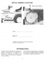
SERIAL
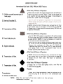
I nternational Cub Cadet 1250, 1450,
and 1650 Tractors
NUMBER
1
LOCATION
'J
EQUIPMENT LIFT HANDLE
3
INTRODUCTION
Height adjustment
3
WORK SAFELY-FOllOW
HITCHING
TRACTOR
THESE
RULES
4
INSTRUMENTS AND CONTROLS
BEFORE OPERATING
TRACTOR
YOUR
OPERATING THE ENGINE
EQUIPMENT
TO THE
14
Orawbar
5,6
Three-point hitch
NEW
REAR POWER TAKE-OFF
7
7 to 9
Operating the rear power
take-off with the tractor
in motion
FRONT POWER TAKE-OFF
9,10
THE TRACTOR
16
Operating the front power
take-off clutch
Fuel shut-c.ff valve
Carburetor adjustments
DRIVING
15
Operating the rear power
take-off with the tractor
standing still
Throttle lever
Governor
Lifting the hood
Starting the engine
Stopping the engine
FUELSYSTEM
14
Adjusting
clutch
the power take-off
ELECTRIC LIFT
11 to 13
Adjusting the seat
Clutch and brake pedal
Locking the brake
HYDRAULIC
LIFT
16, 17
18
ENGINE COOLING AND AIR
CLEANER
International Cub Cadet 1000,
and 1200 Tractors
Engine cooling
Dry type air cleaner
Clutch-brake pedal
Gearshift lever
Starting the tractor
Stopping the tractor
Creeper shift lever
Operating the creeper drive
-1-
19
31
CONTENTS
ELECTRICAL
19to21
SYSTEM
STORING
THE TRACTOR
26,27
Ignition switch
Safety starting switch
Charge indicator
Hour meter
EXTRA EQUIPMENT
ACCESSORIES
Spark plug
Motor generator
TROUBLE SHOOTING
28,29
LUBRICATION
29,30
Motor
Removing from storage
AND
27
generator belt
Lights
Fuse
LUBRICATION
GUIDE
International
Cub Cadet
1000 and 1200 Tractors
Rear. tires
Care of ti res
Inflation
Operati'ng pressure for tires
Mounting tires on the rim
Rear wheel weights
Tire chains
LUBRICATION
SPECI FICATIONS
23
FRONT WHEELS
latch
CLUTCH-BRAKE
International Cub Cadet 1000,
and 1200 Tractors
24
Adjusting the clutch
Adjusting the brakes
BRAKES
I nternational Cub Cadet 1250, 1450
and 1650 Tractors
25,26
the brakes
-2-
32 to 34
GUIDE
I nternational Cub Cadet 1250,
1450 and 1650 Tractors
Overloading
Adjusting
TABLE
22
PNEUMATIC TIRES
Front quick attaching
Front wheel toe-in
Turning radius
LUBRICATION
35 to 37
37 to 40
This symbol is used to call your attention to instructions concerning your
personal safety. Be sure to observe and
follow these instructions.
Disengage all clutches
starting the engine.
Use care when pulling
loads or using heavy
equipment.
Use only approved hitch points, and
limit loads to those you can safely carry. Use
counterweight
or wheel weights when suggested in
Operator's Manual.
and shift into neutral before
Handle gasoline with care -it is highly flammable:
-A.
Use approved gasoline container.
B. Never
remove the fuel tank cap or fill the fuel tank when
the engine is running, is hot, or indoors. Also, do
not smoke when working around flammable fuel.
Wipe up spilled gasoline. C. Replace gasoline cap
securely.
To avoid injury, disengage power to any attachments and stop engine before leaving operator's
seat or making any repairs or adjustments.
Know the controls and how to stop quickly.
READ THE OPERATOR'S MANUAL.
During operation do not run the engine in confined
area such as storage building
any longer than is
necessary for immediate
moving of the tractor
outside into the air.
To avoid an accident or injury, do not allow
children or adults to operate the equipment without proper instructions. Keep children, pets, and
bystanders a safe distance away.
Clear work area of objects which
up and thrown.
Keep machine in good operating condition
and
keep safety devices in place. Use guards or shields
as instructed in Operator's Manual.
might be picked
Disengage power to any attachment when transporting or not in use.
It is recommended that the machine be stopped
and inspected for damage after striking a foreign
object and that any damage be repaired before
To prevent an accident, always disengage the
power take-off, shift transmission into neutral, set
the parking brake, stop the engine, and remove
ignition key when leaving the machine unattended.
restarting and operating the machine.
Always turn ignition
"OFF",
depress the brake
pedal, and set the brake pedal lock before working
on the machine. Disengage all implements and shift
the transmission into neutral.
Reduce speed on slopes and in sharp turns to
prevent tipping or loss of control.
Stay alert
hazards.
for
holes in terrain
and other
REMEMBER
-A
careful
operator
insurance against an accident.
hidden
is the
best
Avoid Overturns -Back the tractor up the steepest
portion of the hill to be mowed! If the tractor
cannot do this, the hi II is too steep for safe
operation. When mowing hills, cut down the face
of the hill rather than across to avoid side tipping.
Also, avoid sudden starts, stops, and turns,
especially on steep slopes to avoid an upset.
Before backing the tractor, always look for obstacles or bystanders in the area where the tractor
will move.
To avoid the possibility of an upset, always engage
the clutch slowly, especially on steep slopes. Avoid
quick starts and stops.
Do not allow anyone in the area
discharge opening while mowing.
area has been supposedly cleared
jects, small objects may have been
may be discharged by the mower
NO RIDERS! This machine is designed to safely
carryon Iy the operator. Do not carry passengers or
give rides as serious injury could result.
injury.
4
parallel to the
Although
the
of foreign oboverlooked and
causing serious
Your Cub Cadet Tractor has been safety engineered. Thoroughly acquaint
yourself with all the instruments and controls before attempting to start or
operate the tractor.
Instruments and controls -International
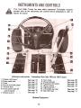
1.
Creeper
2.
Brake
pedal
lock
4.
3.
Clutch
Fuses
and
brake
5.
6.
Throttle
Front
control
7.
Choke
shift
lever
power
lever.
switch.
control.
*
'"
pedal
take-off
...
...
See page 12
Seepage 11
Seepage 20
Seepage 11
Seepage 12
Cub Cadet 1000 and 1200 Tractors
8. Charge
9.
Hour meter.
indicator.
10. Equipment
lift handle
11. Ignition
switch
...
12. Lighting
switch * ..
13. Lift handle cam stop
14. Gear shift lever.
..
See page 16
See page 8
Optional Equipment
5
.
.See
.See
.See
page
page
page
.Seepage
20
20
14
19
See page 14
See page 11
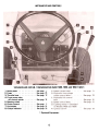
INSTRUMENTSAND CONTROLS
Instruments and controls -International
1. Brake pedal.
2. Fuses
3. Throttle lever.
4. Front power takeoff control switch.
5. Choke
6.
Steering
control.
wheel.
Seepage 11
Seepage20
Seepage 12
7. Hourmeter
8. Chargeindicator.
Seepage 20
Seepage 20
Cub Cadet 1250, 1450, and 1650 Tractors
Seepage 16
Seepage 8
* Optional Equipment
6
3.
4.
OPERATINGTHE ENGINE
COLD WEATHER
STARTING
-Continued
Press the clutch-brake pedal all the way downand
be sure the power take-off switch is in the off
position. The safety interlocks will prevent starting
unless this is done.
Move the key switch into the start position and
hold until the engine starts. As soon as the engine
starts, slowly push the choke in part way.
NOTE: In cold weather the starting motor may
disengage prematurely.
This is caused by the engine
firing once but failing to continue running. If this
happens several times, the engine will be flooded
and it will be necessary to start as described in Step5.
5. Leave the throttle in the slow position but push
the choke in all the way; then turn the ignition key
to the start position and slowly pull the choke out
to the position which will cause the engine to start
and continue running. If the engine falters after
shifting into drive, pull the choke out part way
until the engine runs smoothly, then gradually
push the choke back in as the engine warms.
CAUTION! During operation do not run
the engine in confined area such as
storage building any longer than is
necessary for immediate moving of the tractor
outside into the air.
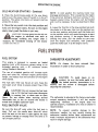
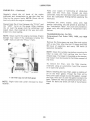
FUEL SYSTEM
CARBURETOR ADJUSTMENTS
This engine is designed to operate on leaded
gasoline with a 93 minimum
octane rating or on
unleaded
gasoline with
a 91 minimum
octane
rating (Research Method).
NOTE:
Air
cleaner
has been removed
illustrations in order to show carburetor.
The use of unleaded gasoline will increase spark
plug and valve life, maintain engine performance
longer, and reduce rust and corrosion of the engine
while stored.
from
A
CAUTION!
To avoid injury or an
accident, be sure the brake pedal is in
The fuel tank filler cap has an air vent. Keep the
the locked position, transmission is in
vent open at all times to assure proper flow of thefuel. neutral, and the mower is disengaged before
adjusting the carburetor.
A
CAUTION! Do not remove the fuel tank
cap or fill the fuel tank when the engine
is running, hot, or when near an openflame.
Do not smoke when working around
The carburetor is adjusted at the factory and under
flammable fuel, as the air around the tractor is
normal operating conditions it will not require
mixed with a highly explosive vapor.
readjusting. However, if the engine does not
operate properly, installation of a new air cleaner is
FUEL SHUT-OFF VALVE
recommended.
Be sure the shut-off valve under the fuel tank is
open. Pullout
the needle stem (shut-off valve)
until the seat on the stem is tight against the stop
to prevent leakage or seepage when the valve is in
its full-open position.
NOTE: To prevent possible damage to
carburetor needles, be very careful closing
carburetor needles before basic adjustments
made. I mproper adjustment of the carburetor
result in engine damage.
9
the
the
are
may
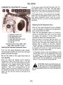
FUEL SYSTEM
CARBURETOR
ADJUSTMENTS
If the engine misses and backfires under load, the
high speed mixture is too lean. The high speed
adjustment screw must be turned counterclockwise
1/8 turn at a time until the condition is corrected.
-Continued
If the engine shows a sooty exhaust and is sluggish
under load, the high speed mixture is too rich. The
high speed adjustment screw must be turned
clockwise 1/8 turn at a time until the condition is
corrected.
Adjusting
the Idle Adjustment
Screw
After the high speed adjustment screw is adjusted,
it may be necessary to readjust the idle adjustment
screw as each affects the other.
Close the idle adjustment screw to its seat by
turning it clockwise; then open it one turn. Start
the engine and operate it at fast idling speed
(without any load) until thoroughly warm.
1. Governor control rod
2. Idle adjustment screw
3. Throttle stop screw
4. High speed adjustment screw
5. Fuel shut-off valve
6. Fuel line
International Cub Cadet 1000, 1200,
1250, 1450, and 1650 Tractors
While the engine is running at fast idle speed, it is
advisable to screw in the throttle stop screw a few
turns to keep the engine from stopping when the
throttle
lever is moved to the fully retarded
"SLOW" position. The engine will then be idling at
a fairly high speed and the throttle stop screw can
be backed out a little at a time until the desired
idle speed is obtained (1800 RPM).
Adjusting the High-Speed Adjustment Screw
Turn the high speed adjustment screw counterclockwise approximately two turns from the closed
position and start the engine.
Be sure the choke
when adjusting.
is fully
open (knob
fully
If the engine misses or rolls while backing out the
throttle stop screw, the idle adjustment screw may
be adjusted in or out until the engine operates
smoothly. Speed up the engine for a few seconds;
then recheck the idle adjustment. A slight adjustment in or out will give the smoothest idle.
in)
After the engine has reached normal operating
temperature, place the throttle lever in the fast
position and turn the high speed adjustment screw
clockwise to the leanest mixture that will allow
satisfactory
acceleration and steady governor
operation. Then, turn counterclockwise to the
richest mixture that allows satisfactory operation.
The difference between the rich and lean points is
about 1/2 turn. Set the mixture to the rich end of
this range.
A
CAUTION!
be fatal!
Do
Carbon monoxide
fumes can
not make any adjustments
to the carburetor in a confined area such
as a storage building. Move the tractor outside into
the air.
10
DRIVING THE TRACTOR
INTERNATIONAL
CUB CADET
TRACTORS
-Continued
GEARSHIFT
1000 AND 1200
LEVER
Before dismounting
always lock the
pedal, disengage the power take-off, and turn the
ignition "OF-F".
lever is used to select various gear ratios
provided in the transmission. There are three
CREEPER SHIFT LEVER
forward speeds and one reverse speed. Refer to"SPECIFICATIONS",
on page 38.
The creeper drive (optional)
STARTING THE TRACTOR
Disengage the clutch by pressing the clutch pedal
all the way down, and release the brake lock. Move
the gearshift lever to the desired speed.
A
CAUTION! To avoid the oossibility of
an upset, always engage the clutch slowly, especially on steep slopes. Avoid
quick starts, stops.
Start the tractor in motion by slowly releasing the
clutch pedal and moving the throttle lever to the
position where the engine operates best for the
load to be handled.
NOTE: When using power take-off operated equipment, best performance is achieved with the
throttle lever in the "Fast" position.
provides a slower
speed in each respective gear, by a four-to-one
reduction in speed from direct drive. When creeper
shift lever is all the way forward,
it is in direct
drive, or all the way rearward, it is in creeper drive.
OPERATING
THE CREEPER
To operate the tractor in creeper drive, depress the
pedal and move the creeper shift lever all the way
rearward. Then select the transmission speed
desired and proceed as instructed under "Starting
the Tractor".
NOTE: Do not use a mid-point position on the
creeper drive as neutral. Neutral position must be
selected only with the standard transmission gearshift lever.
following table shows speeds available
of the three forward gears and reverse gear.
NOTE: Do not shift gears while the engine clutch
is engaged or while the tractor is in motion.
NOTE: Do not rest your foot on the pedal while
driving the tractor, as this will result in excessive
clutch lining wear.
CAUTION! Do not leave the seat of the
tractor without disengaging the brake
pedal and setting the brake lock. If
leaving the tractor unattended, also turn the
ignition key off and remove the key.
in each
SPEED TABLE
Gear
First
Second
be sure the rear wheels are free to turn.
Under any adverse conditions, do not attempt tofree
the tractor by speeding up the engine and
suddenly engaging the clutch. Try backing out
instead of going forward.
DRIVE
Third
Reverse
Miles Per Hour
Direct
Drive
Creeper
Drive
2.3
3.5
6.9
2.5
INTERNATIONAL
CUB
AND 1650 TRACTORS
.6
1.0
1.7
.6
CADET
1250,
1450,
BRAKE PEDAL
Brake pedal must be pressed all the way down to
activate the safety starting switch. When brake
pedal is in the depressed position it automatically
moves the speed control lever to the "N" position.
STOPPING THE TRACTOR
Disengage the clutch by pressing the pedal all the
way down. Move the gearshift lever to the "N"
position.
This
The
Always
12
The tractor can be stopped either by pressing the
pedal all the way down, or placing the speed
control lever in the "N" position.
3.
4.
2.
DRIVING THE TRACTOR
INTERNATIONAL
CUB CADET
AND 1650 TRACTORS -Continued
1250,
Move the speed control lever to start forward
motion.
NOTE: In rotary tilling application,
the
tractor is used to hold the rotary tiller back rather
than to pull the unit as in plowing or mowing.
1450,
NOTE: Do not rest your foot on the brake pedal
while driving the tractor as this would cause the
speed control lever to return to the "N" position.
Move the speed control lever back to a position
to maintain proper mulching of the soil.
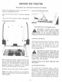
SPEED CONTROL LEVER
5. With a hydrostatic drive, it may
vary the speed control lever as the
With a gear driven tractor,
conditions it may be necessary to
use the brake.
This lever is used to select any speed from a
standstill "N" position to eight miles per hour in
the forward direction and to four miles per hour in
the reverse direction.
be necessary to
soil conditionsvary.
under similar
declutch or to
RELEASE LEVER
Moving the speed control lever forward provides
increased forward speed, and moving the lever
rearward provides the reverse speeds.
Some tractors are equipped with a release lever on
the right side of the frame near the cam stop. To
push or move the tractor for a short distance, the
release lever (if so equipped) must be held in the
(UP) position and the speed control lever (on all
models) must be in the "N" position.
SPEED CONTROL LEVER STOP
An adjustable speed control lever stop is provided
to allow the operator to return to a predetermined
speed.
NOTE: Never operate engine with release lever in
(UP) position. Towing or pushing the tractor for
more than a few feet may result in transmissiondamag
Do not bypass the speed control lever stop to
obtain a higher tractor speed. If a higher speed is
desired, reset the stop.
STARTING THE TRACTOR
1. Depress the brake pedal, release the brake lock,
and let the brake pedal up. Move the throttle lever
to the position where the engine operates best for
the load to be handled.
Start the tractor in motion by moving the speed
control lever slowly forward or rearward as
described above.
STOPPING THE TRACTOR
1. Speedcontrol lever stop
2. Speedcontrol lever
NOTE: On tractors with a rotary
following instructions are required.
tiller
Move the speed control lever to the "N" position
or use the brake. Before dismounting always lock
the brake pedal and turn the ignition "OFF". Also,
disengage the power take-off clutch lever.
the
CAUTION!
To prevent injury or an
accident, do not carry passengersor give
rides. Keep children, pets, and bystanders out of the area.
1. Engage the Power Take-Off clutch, and move
the throttle to "Fast".
2. Lower the rotary tiller to the desired cutting
depth.
13
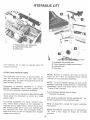
Lock cam itno
clockwise.
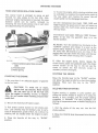
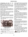
The lift handle is used to lift or lower equipment
used with the tractor. The equipment can be set in
multiple positions by depressing the button on the
top of the handle and releasing it when the desired
position is reached.
this
position
by turning
knob
If free handle travel between cam stop and fully
raised position is desired (Float Position), depress
the release button on top of the handle, press in
the lock button located at the front of the handle
and release the top button.
HEIGHT ADJUSTMENT
If a single implement height is normally used, the
handle may be adjusted to locate the desired
position by use of the cam stop.
NOTE: To disengage the lift handle from the float
position, pull lift handle back slightly and depress
With lift handle in desired implement height
position, release cam by turning locking knob
counterclockwise. Turn cam until it contacts tang.
NOTE:
Refer to the equipment
hitching
instructions.
top button.
manual for proper
1. Lift lever2.
Drawbar3.
Lower mounting points
Drawbar and three-point hitch.
DRAWBAR
1. Releasebutton
2. Lock button
3. Lift handle
Drawbar equipment must be hitched to the tractor
only at the hitch hole in the drawbar.
4. Cam lock knob
5. Cam stop
6. Tang
Adjustable stop limiting handle travel.
14
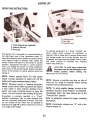
OPERATING
FRONT
POWER TAKE-OFF
The front power take-off clutch is an electric
clutch operated by a toggle switch on the left side
of the instrument panel.
1. Mdve the throttle
"slow"
lever back to the medium or
position.
2. Flip the toggle switch on to the "ON" position.
3. Advance throttle to operating speed (full speed),
ADJUSTING
THE
POWER
TAKE-OFF
CLUTCH
The clutch is factory adjusted and should not
require further adjustment under normal operating
conditions. However, if the clutch fails to operate
properly check as follows:
Check fuse on pedestal.
Using a feeler gauge, check the air gap! I nsert the
feeler gauge into one of the access slots (Ref. 2 in
illustration)
and between the clutch plates. If the
air gap is not .015/.010
inches, adjust the selflocking nuts (Ref. 1) to obtain the proper clear-ance.
Repeat the operation in all four slots.
If the above procedure does not work, see your
I nternational
Harvester dealer.
CAUTION!
To avoid an accident or
possible injury, always disengage all
clutches and shift into neutral before
starting the engine.
...i.
---:..
\
CAUTION! To avoid possible injury,
always disengage all clutches, shift the
transmission into neutral, depress the
brake, set the brake pedal lock and turn the ignition "OFF" before working on the machine.
/
""
q~
MA 10199~"
1. Self-locking nuts (4)2.
Feeler gauge openings (4)
The electric lift is a self-contained
unit designed to
provide power with fingertip control for raising or
lowering mounted equipment.
U
\~
~
~
~~
(()\
16
THE
CLUTCH
The electric
lift is available on all Cub Cadet
Tractors except the Models 1450 and 1650 which
is equipped with a hydraulic lift as standard.
ELECTRICLIFT
OPERATING INSTRUCTIONS
1. Float lockout pin (optional)2.
Electric lift unit3.
Pivot pin
To operate equipment in a fixed "locked"
position, where down pressure of implement is
required (that is blade work); remove frame cover
and remove cotter pin in pivot. Reverse lock pin
(optional) and insert into pre-aligned holes in clevis
and lower portion of rockshaft arm. Replace
washer and cotter pin.
The electric lift is operated by a control switch on
the right-hand side of the instrument panel. To
raise the implement push upward on control switch
until desired height is reached, then release the
switch. Switch will return to the center or neutral
position. Equipment will stay in a given position
when you release the switch. To lower equipment
push down on the control switch. Switch will again
return to the central or neutral position when you
release it.
CAUTION! To avoid injury, always stop
the engine and set the brake pedal in the
locked position before making any
adjustments to the machine.
NOTE:
Always operate elctric lift with tractorengine
running. Operation of electric lift off the
battery will cause premature battery failure.
NOTE:
Remove or position cam stop on side of
frame for full travel of rockshaft before locking
rockshaft arms as described above.
NOTE:
Whenever raising or lowering equipment
release control switch when equipment has reached
a fully raised or lower position. Holding control
NOTE: To avoid possible damage, as soon as the
switch will cause protective
switch to open thecircuit. operation requiring "Down Pressure" is completed,
Lift will function after waiting 30 seconds.
immediately return the float lockout pin to the
"Free to Float" position.
Equipment is normally operated in a "Float"
position (implement free to move upward) with
lock pin (optional) positioned as shown. Cam stop
on the outside of the frame may be adjusted as
described on page 14 to allow implement to return
to a single preset height.
Refer to equipment manual for proper mounting
instructions.
NOTE: Periodically
drops of engine oil.
17
lubricate
pin
"A"
with
a few
ELECTRICALSYSTEM
CHARGE INDICATOR
The
headlights
are
II S P E C I F I CAT
This instrument indicates whether the alternator is
charging or the battery is discharging. If it shows
discharge continuously, investigate the cause to
avoid completely discharging the battery and
possible damage to the charging circuit.
necessary.
sealed-beam
units.
Refer
ION S II when replacement
to
is
To replace the taillight lamp, remove the lens from
the
taillight
and
replace.
Refer
to
"SPECIFICATIONS".
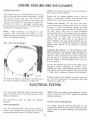
HOUR METER
A49S2~
Checking the spark plug gap.
Set gap at .O25-inch.
Red
White
MA-16231
NOTE: Remove all dirt from around the spark plug
before removing.
The International Cub Cadet Tractors are equipped
with an hour meter which is located on the
instrument panel. It indicates the actual hours of
engine operation, enabling the operator to determine without guesswork, when lubrication, change
of oil or periodic inspections are necessary. It also
provides a means of computing cost of specific
jobs. The hour meter operates whenever the engine
is running or the ignition key is in the "ON"
Remove the spark plug, always using a spark plug
wrench, after every 100 hours of operation to
check the gap.
To avoid possible injury, be
sure engine is off and cool before making
adjustments or repairs.
position.
Replace a defective plug with a new plug. See your
I nternational
Harvester dealer for the correct
The red dial indicates the number of hours from
0 to 60. The yellow dial indicates the total hours
of operation up to 600. For one revolution of the
red dial the yellow dial moves 1/10 of a revolution.
The white dial indicates that the hourmeter is
replacement plug.
FUSES
(Electric
lighting
and
Electric
Power
operating.
Take-Off Clutch)
LIGHTS
Always use the same capacity fuse for replacement.
Refer to "Specifications". If the lights fail or the
electric clutch does not engage, check the appro.
priate fuse.
Lights are optional on all models except the
Models 1450 and 1650.
CAUTION!
20
ELECTRICALSYSTEM
FUSE. Continued
NOTE: There are two fuses adjacent to the lighting
switch on the tractor pedestal (left side). The lower
fuse is for the lights; the upper fuse is for the
electric clutch.
install a new fuse, press in on the fuse housing
cap and turn counterclockwise to remove it from
the fuse housing. Remove the old fuse and replace
it with a new one. Then reassemble the cap to the
housing.
Before working on any part of the electrical
system, disconnect the battery ground cable at the
battery negative (-j terminal. Do not reconnect this
cable until all work has been completed. This will
prevent shorting and damage to any of the electrical units. Examine the electrcial cables occasionally to be sure they are not being frayed by
contact with adjacent parts.
When replacing a battery, make certain the ground
cable is connected to the negative (-) terminal on
the battery. Be sure the rubber boot is properly
positioned over the positive (+) terminal on the
battery. NOTE: Both cables must be assembled
with the nuts to the inside of the terminals to
prevent shorting against fender well.
Cleaning and Servicing the Battery
Occasionally remove the battery cables and
brighten the terminal contact surfaces with wire
wool, and reassemble them. Apply a light coat of
vaseline or chassis lubricant. Be sure the terminals
are clamped tightely and that the battery is
fastened securely in the battery box. Replace
unserviceable cable. Keep the vent holes in the
battery filler caps open.
Keeping the battery fully charged not only adds to
its life but makes it available for instant use when
needed.
Level
Check the battery
electrolyte level.
To
Liquid
21
at least once a month for
The electrolyte (acid and water) in each cell should
be at ring level at all times to prevent battery
failure. When the electrolyte
is below this level,
add pure, distilled water.
Acid or electrolyte should never be added except
by a skilled battery man. Under no circumstances
add any special battery "dopes", solutions or
powders.
CAUTION! If the tractor is to be tipped
up or on its side remove the batteries to
avoid spilling the electroyte. Battery
electrolyte is poisonous and can be injurious to
eyes, skin, and clothing. If electrolyte is spilled,
flush immediately with water, followed by a
solution of one part baking soda to four partswater.
Connecting Booster Batteries
When required, a booster 12-volt battery may be
connected in parallel with the 12-volt system on
I nternational Cub Cadet Tractors.
CAUTION! Gas discharged by batteries
is explosive. Avoid sparks near the
batteries.
NOTE: All circuits must be turned "off".
Electrical system is NEGATIVE
(-) grounded only.
Reversed polarity will result in permanent damage
to components of the electricat system.
The first jumper cable must connect the positive
(+) terminal of the booster battery and the positive
terminal of the battery on the tractor.
The second jumper cable must first be connected
to the negative (-) terminal of the booster battery;
and then to a point on the frame of the tractor,
away from the battery, having a good ground, so
no spark occurs near the battery.
For dependable
battery
national Harvester dealer.
service,
see your
I nter-
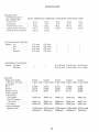
OPERATING
6-12 rear tires are standard equipment
International Cub Cadet 1000 Tractor.
on the
PRESSURE
FOR TIRES
I nflate the front and rear tires for normal or heavy
load operations as shown in the following table.
23 x 8.50-12 high floatation tires are standard
equipment on the I nternational Cub Cadet 1200,
1250, and 1450 Tractors. They are also ayailable as
optiohal
equipment
when ordered for the
International Cub Cadet 1000 Tractor.
Tire Size
Front Tires
Pounds per square inch
12
12
12
12
4.80/4.00-8
16 x 6.50-8
Rear Tires 6-12
23 x 8.50-12
23 x 10.50-12
23 x 10.5-12 tires are standard on the International
Cub Cadet 1650 Tractor.
The high floatation
tires provide maximum
mobility in sand, snow, and soft soil conditions.
The reduced ground pressure and low inflation
provides maximum protection for turf, soil and
crops.
12
REAR WHEEL WEIGHTS
Rear wheel weights increase traction and reduce
wheel slippage. The weights weight approximately
26 pounds each. They are attached to each rear
wheel with two bolts, lock washers, and hex nuts.
If additional weight is desired, a second set of
weights can be attached to each first weight by
using two longer bolts.
CARE OF TIRES
.
Avoid stumps, stones, deep ruts, curbs, and other
hazards. Cuts in tires should te repaired immediately as neglect decreasesthe tire life.
MOUNTING TIRES ON THE RIM
After mounting a new or old tire on the rim,
inflate it to 20 pounds pressure to seat the tire
bead on the rim flange. Then deflate the tire to the
correct operating pressure.
Keep tires free from oil and grease as both destroy
rubber.
After using the tractor for spraying use water to
remove any chemicals that may be on the tires.
TIRE CHAINS
Tire chains will provide additional traction for wet
ground conditions, when plowing snow, or pulling
heavy loads. Rear wheel weights are recommended
when using chains.
INFLATION
Keep the pneumatic tires properly inflated. Overinflation
will cause operator discomfort.
Underinflation will cause short tire life.
OVERLOADING
Always see that the tire valve caps are in place and
tightened securely to prevent loss of air and
protect the valve core and stem.
Do not overload the tractor tires by mounting
equipment on the tractor which exceeds the load
capacity of the size of the tires on the tractor.
22
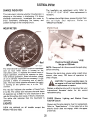
FRONT QUICK ATTACHING
LATCH
latch is used for front and center mountedequipment.
Refer to the equipment manual for
proper instructions.
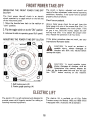
FRONT WHEEL TOE-IN
This
Tie
To
TURNING
CAUTION!
rod and drag link ball joints.
1. Front quick attaching latch
The front wheel toe-in dimension is approximately
liB-inch closer in front than in the rear. To
measure for proper toe-in, make a chalk mark on
the centerline of each tire the same height from the
ground as the front wheel hubs. Measure the
distance between the marks "A", then rotate the
tires so that the marks are toward the rear of the
tractor, the same height from the grou nd as they
were in front. The dimension should be approximately liB-inch larger at the rear. See "B".
Front wheel adjustments.
adjust the toe-in remove one ball joint, loosen
the lock nut "c" at the ball joint and turn the tie
rod ball joint in or out as required.
RADIUS
The front wheel should have an equal angle for left
and right turns. I f adjustment is necessary, remove
ball joint and loosen lock nut "0", turn the drag
link ball joint clockwise or counterclockwise
as
requ ired.
1. Wheel hub
Be sure all parts are reassembled tight with cotter pins in placeand
spread.
Front wheel adjustments.
23
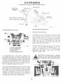
International Cub CCKJet1250, 1450, and 1650 Tractors
""
""
Speed control handle
centering zone when
brake pedal is used
""
"N" position.
I
neutral
r)I
I /
I I
Braking zone.
Brake must be
engaging
With pedal lock in position as
shown brakes must withstand a
torque of 100 fl.lbs. per wheel ~
,-.. - ".01..:~.o
o~
'
rt-°.
-r:::r:::-::.::::::i
--~..
-
+~
~
'0
--00--
~
I
I
I/o,i
~~: -;T
~o=-=::;:=:=-::=:=:::':':~~:.=:.'
0 ,.°ft-;L-.
0
,
' 0
, I
Pedal
stop -,
L I -o~
r°"T°r--rr"
;..L
r
o.
..-
o-
..
~
Wear zone
Brake adjustments.
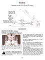
ADJUSTING
Hydrostatic
THE BRAKES
-Continued
Drive Tractors With Disc Brakes Only
The disc brakes should start to engage when the
pedal is pressed down to within a maximum of
1-3/16-inches and a minimum of 3/4-inch above
the pedal stop.
The brake is engaged when pedal arm is at least
3/4-inch above pedal stop.
NOTE: The brakes must not engage before pedal is
within the maximum distance of 1-3/16-inches.
With rear wheels off the ground and brake pedal in
the locked position, the brake settings should be
Adjust to 100 ft. Ibs. per wheel as shown in
equalized as follows:
illustration. Block the front wheels securely and
raise the tractor so the rear wheels are off theground.
Disconnect left brake rod at the pinned end, rotate
the right wheel by hand and adjust the jam nuts on
the brake rod until the wheel brakes firmly. Then,
disconnect the right brake rod at the pinned end
A
CAUTION!
To
avoid
injury,
always
stop
and reconnect the left brake rod. Turn the left
the
engine
and
set the
brake
pedal
in the
wheel by hand and adjust the jam nuts until the
locked position before making any
wheel brakes firmly. Reconnect the right rod.
adjustments to the machine.
25
BRAKES
International Cub Cadet 1250, 1450, and 1650 Tractors
ADJUSTING THE BRAKES
Continued
CAUTION! To avoid injury or possible
accident, be very careful and take necessary precautions when raising tractor
off the ground.
To adjust the brake, loosen jam nut "B". Next,
tighten the brake lever adjusting screw "c"
until
finger tight (8 -1 a-inch pounds). Tighten jam nut
"B" while holding the adjusting screw.
If the brake drags after tightening jam nut "B",
loosen the jam nut and back off adjusting screw
"c" slightly and retighten jam nut "B". Recheck
brake adjustment and insure proper brake operation before operating the tractor.
ator is the
accident.
Remember -A careful operbest insurance against an
When your tractor is not to be used for some time,
it should be stored in a dry and protected place.
Leaving your tractor out-doors, exposed to the
elements materially shortens its life.
Drain the fuel tank and run the engine until the
fuel is exhausted from the fuel system.
Follow the procedure outlined below when storing
a tractor for an extended period of time.
NOTE: Gum will eventually form in the fuel tank,
line, and carburetor
if the fuel system is notdrain
1. Wash or clean and completely lubricate the
tractor. See the "lubrication Guide".
5. After the engine has cooled, remove the spark
plug
and
pour
two
tablespoonsful
of
a
rust
inhibited
oil such as Hy- Tran@ or I H No.1 @
2. Store the tractor so the tires are protected from
engine oil into the cylinder. Crank engine slowly to
sunlight. Before storing the tractor, clean the tire$thoroughly.
distribute
the oil over the cylinder walls. Then
Jack up the tractor so the load is off
replace spark plug.
the tires when it is to be out of service for a long
period. If not jacked up, inflate the tires at regularintervals.
Clean the exterior of the engine.
If tractor is jacked up or
placed on blocks, be sure it is done so it
cannot be tipped over or fall on
someone.
7. Remove the battery and place it in a cool, dry
place above (+320 F.). Check battery at least once
a month for electrolyte level and amount ofchar
See page 21.
3. Run the engine long enough to thoroughly vI/arm
the oil in the crankcase and then drain the oil.
Refill the crankcase with fresh oil as specified in
the "Lubrication
Table" and run the engine for
about five minutes.
8. On all gear driven I nternational
Cub Cadet
Tractors press clutch and brake pedal all the way
down and engage the brake pedal lock. This will
prevent clutch lining from sticking to pressure
plate.
4.
6.
CAUTION!
26
4.
STORINGTHE TRACTOR
REMOVING
FROM STORAGE
1. Fill the fuel tank and be sure the grade of oil in
the crankcase is according to the temperature range
in the "lubrication
Table".
2. Install a fully
connect.
A
CAUTION!
Keep doors wide open or
release brake pedal lock and move the
machine outside the storage room before
engine is started to avoid the danger from exhaust
gas.
charged battery and properly
Check air pressure in tires.
3. Start the engine and let it run slowly. Do not
accelerate it rapidly or operate at high speed
immediately after starting.
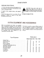
When you purchased your tractor, you probably
had it completely equipped for your particular
needs at the time. However, later you may wish to
obtain some of the equipment or accessories shown
below. These items and other allied equipment can
be purchased from,
and installed by, your
I nternational Harvester dealer.
The tractor is used for so many different types of
work, and because it is called on to operate under
so many different conditions, a variety of equipment is available to adapt it to the requirements of
the user.
Models used on
Spring.
Helper
Pin.
Hitch
Handle
Take-Off
Weights
Wheels.
Drive
Lift
Lighting.
Cover
Box
Lockout
Rear
Power
Wheel
Chains
Creeper
Dual
Electric
Electric
Float
Implement
Rear
Rear
Three-Point
Tire
Tractor
Utility
Type of Equipment
27
1000
1200
1250
1450
1650
x
x
x
x
x
x
x
x
x
x
x
x
x
x
x
x
x
x
x
x
x
x
x
x
-
-
-
x
x
x
x
x
x
x
x
x
-
-
x
x
x
x
x
x
x
x
x
x
x
x
x
x
x
TROUBLESHOOTING
Possible Remedy
Possible Cause
ENGINE OVERHEATS
Keep the air intake area and cooling fins clean; see
."Engine
Cooling and Air Cleaner" on page 20.
.Richen;
see carburetor on page 9 and 10.
Insufficient cool air, dirty air intake screen,
Carburetor
shroud, or set
cooling
to lean
fins.
CREEPING
Speed control out of adjustment (Models
1250, 1450, and 1650)
..,
.Refer
to Service Manual.*
See your International Harvester dealer.
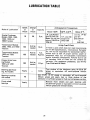
ENGINE OIL
designed for heavy duty service in gasoline engines,
and is formulated
to minimize metallic deposits,
lengthen spark plug and valve life. I H Low Ash Oil
used with unleaded gasoline is the ideal combination to maintain performance and extend engine
The engine crankcase is filled with ship-away oil.
This oil may be used for the first 30 hours of
engine operation
at temperatures
between +90
degrees F. and 0 degrees F. I f temperatures are not
within this range, drain the oil from the crankcase
and replace with
new oil as specified
in the
"lubrication
Table".
The engine oil must be
drained and replaced with new oil every 30 hours
of engine operation.
life.
page31.
I f other than I H Low Ash Engine Oil is used it
must meet API Service Classification
SE. For
maximum engine life select API SE oils with lowest
levels of barium, calcium, or magnesium additives
and minimum
ash content (approximately
0.5%).
Lubricant
suppliers
will
normally
furnish
this
information
on their engine oils.
We recommend
IH Low Ash Engine Oil for
gasoline engines. I H Low Ash Engine Oil exceeds
API Service Classification
SE. It is specifically
Multi-viscosity numbered oils such as SAE 10W-30
or SAE 10-40 must not be used above 32 degrees
Farenheit.
To aid starting, the selection of crankcase lubricating oils should be based on the lowest anticipated temperatures until the next drain period. See
29
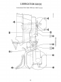
LUBRICATION G UIOE
International Cub Cadet 1000 and 1200 Tractors
-After
1 -Oil filler cap and bayonet-type
level gauge
oil
Every 10 Hours of Operation
Check the oil (with the engine stopped) and add sufficient
new oil to bring it to the "FULL"
mark on the gauge. Do
not overfill.
Do not operate the engine if the oil level is
below the "LOW"
2 -Steering
knuckles
(2).
mark on the gauge.
Use I H 251 H EP grease or equivalent #2 multi-purpose
lithium grease and apply sufficient grease to flush out old
grease and dirt.
3 -Front axle pivot pin.
Use I H 251 H EP grease or equivalent #2 multi-purpose
lithium grease and apply sufficient grease to flush out old
grease and dirt. NOTE: It may be necessary to rotate the
front axle to reach the greasefitting.
-After
4 -Engine
crankcase.
5 -Clutch shaft.
While the oil is warm, remove the drain plug (4) and drain
all of the oil from the crankcase. Replace the drain plug.
Refill the crankcase with new oil up to the "FULL"
mark
on the oil level gauge. Refer to the "Lubrication
Table"
for the proper quantity and viscosity to use.
Remove the frame cover. Usi ng I H 251 H E P grease or
equivalent No.2
multi-purpose
lithium grease, apply two
strokes of lubrication to the fitting.
-After
6 -Power take-off shafting bearing.
Every 30 Hours of Operation
Every 150 Hours of Operation
Use I H 251 H EP grease or equivalent #2 multi-purpose
lithium
grease and apply two or three strokes of the
lubricator to the lubrication fittings.
NOTE: When the red hand of the hour meter is in the red areas maintenance is required.
33
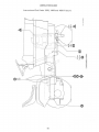
LUBRICATIONGUIDE
International Cub Cadet 1000 and 1200 Tractors
-Periodic
Transmission
'7 -Oil level and filler
8 -Oil drain plug.
plug
Check the oil level periodically.
Keep the lubricant
level plug 7 on the rear of the transmission case.
up the
Creeper drive housing
9 .Level plug.
10. Breather and filler
11 .Drain plug.
Check the oil level periodically.
Keep the lubricant up to
the level plug 9 on the left side of the creeper drivehousin
plug.
Once a year, apply two strokes of the lubricator,
H EP grease or equivalent #2 multi-purpose
using I H251
lithium
grease.
12 -Steering
gear housing.
Miscellaneous
NOTE: To locate the lubrication
fitting,
remove bottom
shield and turn the front wheels to the maximum
right
turn position. Then reach up under the right side of the
tractor frame to locate the fitting.
Lubricate the clutch pedal shaft and linkage with
ten drops of engine oil.
34
eight or
2.
3.
4.
5.
1
6.
7.
LUBRICATIONGUIOE
International Cub Cadet 1250, 1450 and 1650 Tractors
-After
Every 10 Hours of Operation
~ Check the oil (with the engine stopped) and add sufficient
1. Oil filler cap and bayonet-type
level gauge
oil
new oil to bring it to the "FULL"
mark on the gauge. Do
not overfill.
Do not operate the engine if the oil level is
below the "LOW" mark on the gauge.
Steering Knuckles (2),
f NOTE: After the first 10 hours only, remove the old filter
Transmission
oil filter.
and replace with a new filter as instructed
on page 30.
Change the oil filter after 50 hours and every 100 hours of
operation thereafter.
-After
Front Axle pivot pin.
Every 30 Hours of Operation
Use IH 251H EP grease or equivalent #2 multi-purpose
lithium grease and apply sufficient grease to flush out old
grease and dirt. NOTE: It may be necessary to rotate the
front axle to reach the greasefitting.
While the oil is warm, remove the drain plug (5) and drain
all of the oil from the crankcase. Replace the drain plug.
I Remove the crankcase oil filler
cap (1). Refill the
Engine crankcase.
crankcase with new oil up to the "FUll"
level gauge. Refer to the "lubrication
, proper quantity and viscosity to use.
-After
Transmission oil f1lter.
Every 50 Hours of Operation
NOTE: After the first 50 hours only, remove the old filter
and replace with a new filter as instructed
on page 30.
Change the oil filter
every 100 hours of operation
thereafter.
-After
Transmission oil filter.
mark on the oil
Table" for the
Every 100 Hours of Operation
{ Change
the
oil
filter
and
replace
with
a new filter
as
instructed on page30,
-Periodic
Transmission
Oil level and filler plug
NOTE:
Check the oil level periodically. Keep the lubricant up to
the level plug (8) on the rear of the transmission case8.
t cover.
When the red hand of the hour meter is in the red areas
maintenance is required.
36