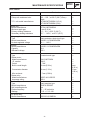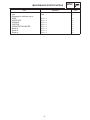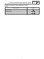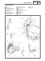
1
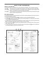
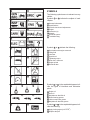
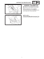
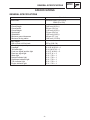
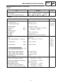
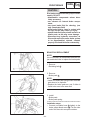
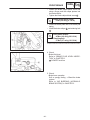
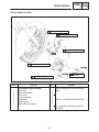
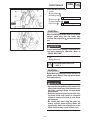
FOREWORD This Supplementary Service Manual has been prepared to introduce new service and data for the XVS650AN(C). For complete service information procedures it is necessary to use this Supplementary Service Manual together with the following manual. XVS650AK(C) SERVICE MANUAL: LIT-11616-11-16 (5BN-28197-E0) XVS650AN(C) SUPPLEMENTARY SERVICE MANUAL 2000 by Yamaha Motor Corporation, U.S.A. First edition, October 2000 All rights reserved. Any reproduction or unauthorized use without the written permission of Yamaha Motor Corporation, U.S.A. is expressly prohibited. Printed in U.S.A. P/N LIT-11616-14-31 EB001000 NOTICE This manual was produced by the Yamaha Motor Company primarily for use by Yamaha dealers and their qualified mechanics. It is not possible to include all the knowledge of a mechanic in one manual, so it is assumed that anyone who uses this book to perform maintenance and repairs on Yamaha motorcycles has a basic understanding of the mechanical ideas and the procedures of motorcycle repair. Repairs attempted by anyone without this knowledge are likely to render the motorcycle unsafe and unfit for use. This model has been designed and manufactured to perform within certain specifications in regard to performance and emissions. Proper service with the correct tools is necessary to ensure that the motorcycle will operate as designed. If there is any question about a service procedure, it is imperative that you contact a Yamaha dealer for any service information changes that apply to this model. This policy is intended to provide the customer with the most satisfaction from his motorcycle and to conform with federal environmental quality objectives. Yamaha Motor Company, Ltd. is continually striving to improve all of its models. Modifications and significant changes in specifications or procedures will be forwarded to all authorized Yamaha dealers and will appear in future editions of this manual where applicable. NOTE: This Service Manual contains information regarding periodic maintenance to the emission control system. Please read this material carefully. Designs and specifications are subject to change without notice. IMPORTANT INFORMATION Particularly important information is distinguished in this manual by the following notations. The Safety Alert Symbol means ATTENTION! BECOME ALERT! YOUR SAFETY IS INVOLVED! WARNING CAUTION: NOTE: Failure to follow WARNING instructions could result in severe injury or death to the motorcycle operator, a bystander or a person inspecting or repairing the motorcycle. A CAUTION indicates special precautions that must be taken to avoid damage to the motorcycle. A NOTE provides key information to make procedures easier or clearer. EB002000 HOW TO USE THIS MANUAL MANUAL ORGANIZATION This manual consists of chapters for the main categories of subjects. (See “Illustrated symbols”) 1st title 1 : This is the title of the chapter with its symbol in the upper right comer of each page. 2nd title 2 : This title indicates the section of the chapter and only appears on the first page of each section. It is located in the upper left comer of the page. 3 3rd title : This title indicates a sub-section that is followed by step-by-step procedures accompanied by corresponding illustrations. EXPLODED DIAGRAMS To help identify parts and clarify procedure steps, there are exploded diagrams at the start of each removal and disassembly section. 1. An easy-to-see exploded diagram 4 is provided for removal and disassembly jobs. 2. Numbers 5 are given in the order of the jobs in the exploded diagram. A number that is enclosed by a circle indicates a disassembly step. 3. An explanation of jobs and notes is presented in an easy-to-read way by the use of symbol marks 6 . The meanings of the symbol marks are given on the next page. 4. A job instruction chart 7 accompanies the exploded diagram, providing the order of jobs, names of parts, notes in jobs, etc. 5. For jobs requiring more information, the step-by-step format supplements 8 are given in addition to the exploded diagram and the job instruction chart. 2 1 6 3 8 5 4 7 EAS0009 1 2 3 SYMBOLS The following symbols are not relevant to every vehicle. Symbols 1 to 8 indicate the subject of each chapter. 4 1 2 3 4 5 6 7 8 General information Specifications Periodic checks and adjustments Engine Carburetor(-s) Chassis Electrical system Troubleshooting 5 6 7 8 9 10 Symbols 9 to 16 indicate the following. 11 12 9 Serviceable with engine mounted 10 Filling fluid 11 Lubricant 12 Special tool 13 Tightening torque 14 Wear limit, clearance 15 Engine speed 16 Electrical data 13 14 15 16 17 20 23 18 19 21 22 24 Symbols 17 to 22 in the exploded diagrams indicate the types of lubricants and lubrication points. 17 18 19 20 21 22 Engine oil Gear oil Molybdenum disulfide oil Wheel bearing grease Lithium soap base grease Molybdenum disulfide grease Symbols 23 to 24 in the exploded diagrams indicate the following: 23 Apply locking agent (LOCTITE) 24 Replace the part CONTENTS GENERAL INFORMATION . . . . . . . . . . . . . . . . . . . . . . . . . . . . . . . . . . . . . . MOTORCYCLE IDENTIFICATION . . . . . . . . . . . . . . . . . . . . . . . . . . . . VEHICLE IDENTIFICATION NUMBER . . . . . . . . . . . . . . . . . . . . . MODEL LABEL . . . . . . . . . . . . . . . . . . . . . . . . . . . . . . . . . . . . . . . . . . 1 1 1 1 SPECIFICATIONS . . . . . . . . . . . . . . . . . . . . . . . . . . . . . . . . . . . . . . . . . . . . . GENERAL SPECIFICATIONS . . . . . . . . . . . . . . . . . . . . . . . . . . . . . . . . MAINTENANCE SPECIFICATIONS . . . . . . . . . . . . . . . . . . . . . . . . . . . ENGINE . . . . . . . . . . . . . . . . . . . . . . . . . . . . . . . . . . . . . . . . . . . . . . . . CHASSIS . . . . . . . . . . . . . . . . . . . . . . . . . . . . . . . . . . . . . . . . . . . . . . . ELECTRICAL . . . . . . . . . . . . . . . . . . . . . . . . . . . . . . . . . . . . . . . . . . . LUBRICATION POINTS AND LUBRICANT TYPES . . . . . . . . . . . . . . ENGINE . . . . . . . . . . . . . . . . . . . . . . . . . . . . . . . . . . . . . . . . . . . . . . . . CABLE ROUTING . . . . . . . . . . . . . . . . . . . . . . . . . . . . . . . . . . . . . . . . . . 2 2 3 3 3 4 6 6 7 PERIODIC INSPECTION AND ADJUSTMENT . . . . . . . . . . . . . . . . . . . . 16 REAR BRAKE ADJUSTMENT . . . . . . . . . . . . . . . . . . . . . . . . . . . . . . . . 16 SHIFT PEDAL ADJUSTMENT . . . . . . . . . . . . . . . . . . . . . . . . . . . . . . . . 18 CARBURETION . . . . . . . . . . . . . . . . . . . . . . . . . . . . . . . . . . . . . . . . . . . . . . . AIR INDUCTION SYSTEM . . . . . . . . . . . . . . . . . . . . . . . . . . . . . . . . . . . AIR INDUCTION SYSTEM DIAGRAMS . . . . . . . . . . . . . . . . . . . . . CHECKING THE AIR INDUCTION SYSTEM . . . . . . . . . . . . . . . . 19 19 19 22 CHASSIS . . . . . . . . . . . . . . . . . . . . . . . . . . . . . . . . . . . . . . . . . . . . . . . . . . . . . FRONT BRAKE . . . . . . . . . . . . . . . . . . . . . . . . . . . . . . . . . . . . . . . . . . . . . FRONT BRAKE PADS . . . . . . . . . . . . . . . . . . . . . . . . . . . . . . . . . . . FRONT BRAKE CALIPER . . . . . . . . . . . . . . . . . . . . . . . . . . . . . . . . 23 23 23 26 WIRING DIAGRAM MOTORCYCLE IDENTIFICATION GEN INFO EB100000 GENERAL INFORMATION MOTORCYCLE IDENTIFICATION EB100010 VEHICLE IDENTIFICATION NUMBER The vehicle identification number 1 is stamped into the right side of the steering head. MODEL LABEL The model label 1 is affixed to the frame. This information will be needed to order spare parts. –1– GENERAL SPECIFICATIONS SPECIFICATIONS GENERAL SPECIFICATIONS Item Model code: Standard XVS650A:5BNT (For U.S.A) 5BNU (For CAL) Dimensions: Overall length Overall width Overall height Seat height Wheelbase Minimum ground clearance Minimum turning radius 2,450 mm (96.5 in) 930 mm (36.6 in) 1,105 mm (43.5 in) 710 mm (28.0 in) 1,625 mm (64.0 in) 145 mm (57.1 in) 3,400 mm (133.9 in) Basic weight: With oil and a full fuel tank 247 kg (544.5 lb) Bulb wattage quantity: Headlight Tail/brake light Front turn signal/position light Rear turn signal light Meter light Neutral indicator light High beam indicator light Turn indicator light Engine indicator light 12 V 60 W/55 W 1 12 V 8 W/27 W 1 12 V 27 W/8 W 2 12 V 27 W 2 12 V 1.7 W 1 12 V 1.7 W 1 12 V 1.7 W 1 12 V 1.7 W 1 12 V 1.7 W 1 –2– SPEC MAINTENANCE SPECIFICATIONS SPEC MAINTENANCE SPECIFICATIONS ENGINE Item Standard Connecting rod: Oil clearance Color code (corresponding size) 0.031 X 0.055 mm (0.0012 X 0.0022 in) 1 Blue 2 Black 3 Brown 4 Green Limit CHASSIS Item Standard Front suspension: Front fork travel Fork spring free length Installed length Spring rate Stroke Optional spring Oil capacity Oil level Oil grade Front brake: Type Disc outside diameter 140 mm (5.5 in) 332.5 mm (3.1 in) (K1) (K1) thickness 287.4 mm (11.3 in) 3.43 N/mm (0.343 kg/mm, 19.2 lb/in) 0 X 140 mm (0 X 5.5 in) No 0.507 L (17.4 US oz) 95 mm (3.74 in) Yamaha fork oil 10 WT or equivalent Single disk 298 5 mm (11.73 Pad thickness inner 6.0 mm (0.24 in) Pad thickness outer 6.0 mm (0.24 in) Master cylinder inside diameter Caliper cylinder inside diameter Caliper cylinder inside diameter Brake fluid type Brake lever & brake pedal: Brake lever free play (at pivot) Brake lever free play (at lever end) Brake pedal position Brake pedal free play Clutch lever free play (at pivot) Clutch lever free play (at lever end) 0.2 in) Limit 325.9 mm (12.83 in) 4.5 mm (0.18 in) 0.8 mm (0.03 in) 0.8 mm (0.03 in) 14.0 mm (0.55 in) 30.2 mm (1.19 in) 33.3 mm (1.31 in) DOT 4 1 X 2 mm (0.04 X 0.08 in) 10 X 15 mm (0.39 X 0.59 in) 108 mm (4.25 in) 20 X 30 mm (0.79 X 1.18 in) 2 X 3 mm (0.08 X 0.12 in) 10 X 15 mm (0.39 X 0.59 in) –3– MAINTENANCE SPECIFICATIONS SPEC ELECTRICAL Item T.C.I.: Pickup coil resistance/color Standard Limit 182 X 222 Ω at 20_C (68_F)/Gray – Black J4T088/MITSUBISHI (U.S.A) J4T128/MITSUBISHI (CAL) SSS Ignition coil: Model/manufacturer Minimum spark gap Primary winding resistance Secondary winding resistance F6T541 /MITSUBISHI 6 mm (0.24 in) 3.6 X 4.8 Ω at 20_C (68_F) 10.7 X 14.5 kΩ at 20_C (68_F) SSS SSS SSS SSS Voltage regulator: Type Model/manufacturer No load regulated voltage Semi-conductor, short-circuit type SH650C-11/SHINDENGEN 14.1 X 14.9 V SSS SSS SSS Rectifier: Model/manufacturer Capacity Withstand voltage SH650C-11/SHINDENGEN 18 A 200 V SSS SSS SSS Constant mesh type SSS SM-13/MITSUBA SM-13 0.7 kW 10 mm (0.39 in) 0.7 mm (0.08 in) SSS SSS SSS 4 mm (0.16 in) 27 mm (1.06 in) SSS MS-5F-441 /JIDECO 180 A SSS SSS Flasher relay: Type Model/manufacturer Self cancelling device Flasher frequency Wattage Semi transistor type FB257H/DENSO Yes 75 X 95 cycle/min 27 W 2 + 3.4 W SSS SSS SSS SSS SSS Fuel pump relay: Model/manufacturer G8R-30Y-Q/OMRON SSS T.C.I. unit model/manufacturer Electric starter system: Type Starter motor: Model/manufacturer I.D. number Output Brush overall length Commutator diameter Mica undercut Starter relay: Model/manufacturer Amperage rating 28 mm (1.10 in) –4– SSS SSS MAINTENANCE SPECIFICATIONS Item Circuit breaker: Type Amperage for individual circuit MAIN HEADLIGHT SIGNALS IGNITION CARBURETOR HEATER Reserve Reserve Reserve SPEC Standard Limit Fuse 30 A 1 15 A 1 10 A 1 10 A 1 15 A 1 30 A 1 15 A 1 10 A 1 –5– LUBRICATION POINTS AND LUBRICANT TYPES SPEC EB203000 LUBRICATION POINTS AND LUBRICANT TYPES ENGINE Symbol Lubrication point Crankshaft journal Camshaft cam lobe Primary driven gear –6– CABLE ROUTING SPEC EB206000 CABLE ROUTING 1 2 3 4 5 6 7 8 9 Frame Clutch cable Left handlebar switch lead Fuel tank breather hose Speedometer cable Speedometer Speedometer light leads Vacuum chamber air vent hose Rectifier/ regulator 10 11 12 13 14 15 16 17 18 Sidestand switch lead Rear brake switch lead Horn Headlight lead Right handlebar switch lead Main switch Main switch lead Fuel pump lead Fuel hose –7– 19 Spark plug lead 20 Fuel pump CABLE ROUTING A Inside the motorcycle. B Place the end of the plastic locking tie as shown. C Fasten the rear brake switch lead, sidestand switch lead and rectifier / regulator lead with metal clamp or plastic locking tie. D Pass the front flasher light leads (left and right) and headlight lead through the headlight cover hole. E Pass the left handlebar switch lead behind the upper bracket. F Fasten the left handlebar switch lead with a plastic locking tie. G Pass the speedometer cable, speedometer light leads and fuel tank breather hose through the fuel tank hole. SPEC H To the speedometer light leads. I Rectifier/ regulator lead should not be out over the bracket. J Pass the right handlebar switch lead and headlight lead over the other harness and leads. K Pass the clutch cable through the cable guide. L Fasten the sidestand switch lead and rectifier / regulator lead with a plastic locking tie. M Install the plastic locking tie so that it is up against the frame projection. N To the engine. O Pass the sidestand switch and the lead wire through the sidestand bracket. When installing, wake sure not to have any extra loosening. –8– CABLE ROUTING P Route the sidestand switch and the lead wire under the frame boss. Q Fasten the sidestand switch lead with a metal clamp. R Connect the rear brake switch coupler in front of the roll over valve stay. S Install the plastic locking tie immediately below the cable guide bracket. T Pass the speedometer cable through the speedometer cable holder. U To the rectifier / regulator. SPEC V Pass the rear brake switch lead between the frame and rectifier / regulator. Do not pinch the rear brake switch lead. W Fasten the rear brake switch lead with a plastic locking tie. X To the speedometer light leads. Y Place the rectifier / regulator coupler completely inside the motorcycle body. Z Pass the fuel tank breather hose and vacuum chamber air vent hose through the holder. AA Pass the speedometer cable through the holder. AB Place the couplers behind the steeirng head. –9– CABLE ROUTING 1 2 3 4 5 6 7 8 9 10 11 12 Frame bracket Dimmer switch Self-canceling turn signal relay Fuse box Battery positive (+) lead Spark plug lead Vacuum chamber air bent hose Starter cable Right handlebar switch lead Brake hose Throttle cables Thermo switch lead 13 14 15 16 17 18 19 20 21 22 23 24 Flasher light relay Starter relay Carburetor heater relay Neutral switch lead Pickup coil lead A.C. magneto lead Battery negative (–) lead Starter motor lead Battery cover Battery Wire harness Starting circuit cut-off relay –10– SPEC 25 Fuel tank breather hose 26 Speedometer cable 27 Ignitor unit A Pass the tail / brake light lead between the frame bracket and battery box. Position the mud guard the between the edge of the frame bracket and the tail/ brake light lead. B Fasten the dimmer switch lead with a clamp. CABLE ROUTING C Fasten the self-canceling turn signal relay lead and battery positive (+) lead with a battery band. D Fasten the tail / brake light lead coupler and battery negative (–) lead coupler with a clamp. E Fasten the starter relay lead and fuse box lead with a plastic locking tie. F To the ignition coil. G The end of the plastic locking tie should face towards the under the handlebar. H Fasten the right handlebar switch lead with a plastic locking tie. SPEC I Pass the right handlebar switch lead behind the upper bracket. J Fasten the brake hose grommet with a brake hose holder. K Place the left handlebar switch coupler on the side of the main switch. L Fasten the brake hose with a brake hose holder. M Pass the left handlebar switch lead under the main switch. N Fasten the spark plug lead with a metal clamp. O Pass the ignition coil lead inside of the starter cable. P Fasten the fuse box lead with a plastic locking tie. –11– CABLE ROUTING Q Fasten the battery positive (+) lead with a battery box clamp. R The carburetor heater relay should not touch the wire harness. S Fasten the wire harness with a plastic locking tie. T Place the end of the plastic locking tie as shown. U From the engine. V Pass the starter motor lead over the battery negative (–) lead. W Fasten the pickup coil lead, A.C. magneto lead, neutral switch lead and starter motor lead with a plastic locking tie. SPEC X Fasten the battery negative (–) lead, starter motor lead and wire harness with a plastic locking tie. Y Fasten the wire harness with a clamp. Z The starting safety relay must be fixed to the battery box after connecting the wire harness. AA Fasten the battery negative (–) lead and tail/ brake light lead with a clamp. AB Pass the wire harness between the frame and battery box. AC Fasten the starter cable with a plastic locking tie. AD Inside the motorcycle. –12– CABLE ROUTING AE Pass the fuel tank breather hose through the holder. AF Fasten the fuel tank breather hose with a metal clamp. AG Pass the speedometer cable through the front side guide. AH To the battery negative (–) lead. AI To the rear fender. AJ To the flasher light relay. AK To the starter relay. AL The wire harness and leads should not touch the rear shock absorber. SPEC AM Fasten the wire harness and leads with a plastic locking tie. AN Pass the plastic band through the frame hole. Fasten the wire harness with a plastic band at the point where the tape is located. AO Fasten the wire harness and leads with a plastic locking tie. AP Fasten the wire harness and leads with a metal clamp. AQ To the carburetor heater relay. AR Pass the ignitor unit leads through the battery box hole. –13– CABLE ROUTING 1 2 3 4 5 6 7 8 9 10 11 12 Front flasher light (right) Throttle cables Brake hose Right handlebar switch lead Clutch cable Left handlebar switch lead Front flasher light (left) Ignition coil Spark plug lead Silencer Starter cable Speedometer cable Neutral switch lead Pickup coil lead A.C. magneto lead Thermo switch lead Fuel tank breather hose Rectifier/ regulator coupler Wire harness Throttle position sensor (TPS) lead 21 Frame 22 Air filter case 13 14 15 16 17 18 19 20 –14– SPEC A Pass the throttle cables through the cable guide. B Pass the left handlebar switch lead over the right handlebar switch lead. C Pass the clutch cable through the cable guide. D Fasten the handlebar switch leads with a plastic band. E To the ignition coil. F Pass the starter cable between the ignition coil and spark plug lead. CABLE ROUTING G H I J To the throttle position sensor (TPS). To the carburetor. To the fuel tank. Pass the neutral switch lead, pickup coil lead and A.C. magneto lead under the ignition coil lead, thermo switch lead and throttle position sensor (TPS) lead. K From the engine. L 20 mm (0.79 in) M Pass the thermo switch lead inside of the silencer breather hose. SPEC N Fasten the wire harness and throttle position sensor (TPS) lead with a plastic locking tie. O Inside the motorcycle. P Route the wire harness and throttle position sensor (TPS) lead so they run along the bottom of the frame tube. Q Place the end of the plastic locking tie as shown. R Fasten the wire harness with a plastic locking tie. S Pass the wire harness between the air filter case groove and frame. –15– REAR BRAKE ADJUSTMENT INSP ADJ PERIODIC INSPECTION AND ADJUSTMENT EB304012 REAR BRAKE ADJUSTMENT 1. Check: Brake pedal height a Out of specification Adjust. Brake pedal height: 108 mm (4.25 in) (above the top of the footrest) 2. Adjust: Brake pedal height *************************************** Adjustment steps: Loosen the locknut 1 . Turn the adjuster 2 in or out until the specified pedal height is obtained. Turning in: brake pedal height is decreased. Turning out: brake pedal height is increased. Tighten the locknut. Locknut: 7 Nm (0.7 mkg, 5.1 ftlb) *************************************** 3. Check: Brake pedal free play a Out of specification Adjust. Free play (brake pedal): 20 30 mm (0.79 1.18 in) 4. Adjust: Brake pedal free play *************************************** Adjustment steps: Turn the adjuster 1 in or out until the specified free play is obtained. Turning in: brake pedal free play is decreased. Turning out: brake pedal free play is increased. CAUTION: Make sure that there is no brake drag after adjusting the brake pedal height and the free play. –16– *************************************** REAR BRAKE ADJUSTMENT INSP ADJ 5. Adjust: Brake light switch Refer to “BRAKE LIGHT SWITCH ADJUSTMENT”. –17– SHIFT PEDAL ADJUSTMENT INSP ADJ EB304080 SHIFT PEDAL ADJUSTMENT 1. Check: Shift pedal position Check the shift pedal rod length a . If the position is incorrect Adjust. Shift pedal rod length: 168 mm (6.6 in) 2. Adjust: Shift pedal position *************************************** Adjustment steps: Loosen both locknuts 1 . To obtain the correct pedal position turn the shift pedal rod 2 in or out. Turning in: shift pedal is lowered. Turning out: shift pedal is raised. Tighten both locknuts. *************************************** NOTE: Align the mark on the shift shaft with the center of the slit. Turn in the both side of the shift pedal rod more than 4 times. –18– AIR INDUCTION SYSTEM EB601000 CARBURETION AIR INDUCTION SYSTEM EAS00509 AIR INDUCTION SYSTEM DIAGRAMS 1 2 3 4 Reed valve Air cut valve Air cleaner Carburetor joint A To the front cylinder head B To the rear cylinder head –19– CARB AIR INDUCTION SYSTEM CARB 2 Nm (0.2 mkg, 1.4 ftlb) 4 Nm (0.4 mkg, 2.9 ftlb) Order 1 2 3 4 5 6 7 8 Job/Part Q’ty Removing the air induction system Reed valve case to front cylinder head hose Reed valve case to front cylinder head pipe Reed valve case to rear cylinder head hose Reed valve case to rear cylinder head hose Gasket Reed valve case to cylinder head pipe Reed valve case to cylinder head hose Vacuum hose 2 –20– Remarks Remove the parts in the order listed. 1 1 1 1 2 1 2 1 AIR INDUCTION SYSTEM CARB 2 Nm (0.2 mkg, 1.4 ftlb) 4 Nm (0.4 mkg, 2.9 ftlb) Order 9 10 11 12 13 14 15 16 17 18 19 Job/Part Q’ty Remarks 1 1 1 1 1 1 1 1 1 1 1 Cover Cover Vacuum hose 1 Air cut valve Plug Air cut valve to air cleaner hose Air cleaner Air Cleaner case Bend hose Air cut valve to reed valve hose Reed valve For installation, reverse the removal procedure. –21– AIR INDUCTION SYSTEM CARB EAS00510 CHECKING THE AIR INDUCTION SYSTEM 1. Check: hoses Loose connection Connect properly. Cracks/damage Replace. pipes Cracks/damage Replace. 2. Check: reed valve 1 reed valve stopper reed valve seat Cracks/damage Replace the reed valve. 3. Measure: reed valve bending a Out of specification Replace the reed valve. Maximum reed valve bending 0.4 mm (0.016 in) 1 Surface plate 4. Check: air cutoff valve Cracks/damage Replace. 5. Check: air cleaner Cracks/damage Replace. Clogged Clean. –22– FRONT BRAKE CHAS CHASSIS FRONT BRAKE FRONT BRAKE PADS 40 Nm (4.0 mkg, 28.9 ftlb) 27 Nm (2.7 mkg, 19.5 ftlb) 27 Nm (2.7 mkg, 19.5 ftlb) Order 1 2 3 4 Job/Part Q’ty Remarks Remove the parts in the order below. Front brake pad removal Retaining bolt Brake caliper Brake pads Pad spring 2 1 2 1 Refer to “BRAKE PAD REPLACEMENT”. For installation, reverse the removal procedure. –23– FRONT BRAKE CHAS CAUTION: Disc brake components rarely require disassembly. DO NOT: disassemble components unless absolutely necessary; use solvents on internal brake components; use spent brake fluid for cleaning; (use only clean brake fluid) allow brake fluid to come in contact with the eyes, as this may cause eye injury; splash brake fluid onto painted surfaces or plastic parts, as this may cause damage; disconnect any hydraulic connection, as this would require the entire brake system to be disassembled, drained, cleaned, properly filled and bled after reassembly. BRAKE PAD REPLACEMENT NOTE: It is not necessary to disassemble the brake caliper and brake hose to replace the brake pads. 1. Remove: Retaining bolt 1 2. Remove: Brake pads 1 NOTE: Install new brake pad springs when the brake pads have to be replaced. Replace the brake pads as a set if either is found to be worn to the wear limit. 3. Install: Brake pads Brake pads spring *************************************** Installation steps: Connect a suitable hose 1 tightely to the brake caliper bleed screw 2 . Put the other end of this hose into an open container. –24– FRONT BRAKE CHAS Loosen the brake caliper bleed screw and using a finger push the caliper pistons into the brake caliper. Tighten the brake caliper bleed screw 2 . Brake caliper bleed screw: 6 Nm (0.6 mkg, 4.3 ftlb) Install new brake pads and a new brake pad spring. Install the brake caliper 3 and retaining bolt 4. Bolt (brake caliper): 40 Nm (4.0 mkg, 28.9 ftlb) Retaining bolt: 27 Nm (2.7 mkg, 19.5 ftlb) *************************************** 4. Check Brake fluid level Refer to “BRAKE FLUID LEVEL INSPECTION” in CHAPTER 3. a “LOWER” level line 5. Check: Brake lever operaiton Soft or spongy feeling Bleed the brake system. Refer to “AIR BLEEDING (HYDRAULIC BRAKE SYSTEM)” in CHAPTER 3. –25– FRONT BRAKE CHAS FRONT BRAKE CALIPER 7 Nm (0.7 mkg, 5.1 ftlb) 30 Nm (3.0 mkg, 21.7 ftlb) 6 Nm (0.6 mkg, 4.3 ftlb) 40 Nm (4.0 mkg, 28.9 ftlb) 27 Nm (2.7 mkg, 19.5 ftlb) 27 Nm (2.7 mkg, 19.5 ftlb) Order 1 2 3 4 5 6 Job/Part Q’ty Remarks Remove the parts in the order below. Drain Front brake caliper removal Brake fluid Brake hose holder Union bolts Copper washers Brake hose Retaining bolt Brake caliper assembly 1 1 2 1 2 1 Refer to “CALIPER INSTALLATION”. For installation, reverse the removal procedure. –26– CHAS FRONT BRAKE CALIPER INSTALLATION 1. Install: Brake caliper 1 Retaining bolt 2 27 Nm (2.7 mkg, 19.5 ftlb) Brake hose 3 Copper washers 4 New Union bolt 5 30 Nm (3.0 mkg, 21.7 ftlb) CAUTION: When installing the brake hose on the brake caliper, make sure that the brake pipe touches the projection a on the brake caliper. WARNING Proper brake hose routing is essential to insure safe motorcycle operation. Refer to “CABLE ROUTING”. 2. Fill: Brake reservoir Recommended brake fluid: DOT 4 CAUTION: Brake fluid may damage painted surfaces or plastic parts. Always clean up spilled brake fluid immediately. WARNING Use only the designated quality brake fluid: other brake fluids may deteriorate the rubber seals, causing leakage and poor brake performance. Refill with the same type of brake fluid: mixing brake fluids may result in a harmful chemical reaction and lead to poor brake performance. Be careful that water does not enter the master cylinder when refilling. Water will significantly lower the boiling point of the brake fluid and may result in vapor lock. –27– FRONT BRAKE CHAS 3. Air bleed Brake system Refer to “AIR BLEEDING (HYDRAULIC BRAKE SYSTEM)” in CHAPTER 3. 4. Check: Brake fluid level Brake fluid level is under the “LOWER” level line Fill up. Refer to “BRAKE FLUID LEVEL INSPECTION” in CHAPTER 3. a “LOWER” level line –28– XVS650AN(C) WIRING DIAGRAM 1 2 3 4 5 6 7 8 9 10 11 12 13 14 15 16 17 18 19 20 21 22 23 24 25 26 27 28 29 30 31 32 33 34 35 36 37 38 39 40 41 42 43 44 45 46 COLOR CODE B . . . . . Black Br . . . . Brown Ch . . . Chocolate Dg . . . Dark green G . . . . Green Gy . . . Gray L ..... Lg . . . . O .... P ..... R..... Sb . . . . Blue Light green Orange Pink Red Sky blue W .... Y ..... B/L . . . B/W . . B/Y . . . Br/B . . White Yellow Black/Blue Black/White Black/Yellow Brown/Black Br/L . . Br/W . Br/Y . . G/Y . . L/B . . . L/R . . . Brown/Blue Brown/White Brown/Yellow Green/Yellow Blue/Black Blue/Red L/W . . L/Y . . . R/B . . . R/W . . R/Y . . . Blue/White Blue/Yellow Red/Black Red/White Red/Yellow A.C. magneto Rectifier/ regulator Main switch Battery Main fuse Starter relay Starter motor Relay unit Fuel pump Sidestand switch Throttle position sensor (TPS) Ignitor unit Ignition coil Spark plug Pickup coil Neutral switch Meter assembly Engine indicator light Neutral indicator light Meter light High beam indicator light Turn indicator light Rear turn signal Front turn signal Headlight Left handlebar switch Dimmer switch Horn switch Clutch switch Turn switch Flasher relay Horn Rear brake switch Tail/ brake light Carburetor heater Carburetor heater earth Carburetor heater relay Thermo switch Carburetor heater fuse Signal system fuse Headlight fuse Ignition fuse Right handlebar switch Front brake switch Engine stop switch Start switch PRINTED IN U.S.A. 99 S 11 - 0.4 1