1
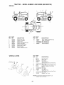
TRACTOR
Model
425014X92E
(96014000100)
INSTRUCTION
BOOK
Read
and keep this book for future
reference.
This book contains important
information
on
SAFETY, ASSEMBLY,
OPERATION,
MAINTENANCE
PRODUCT
& STORAGE.
INFORMATION
The owner must be certain that all the product information
is included with the unit. This information
includes the INSTRUCTION
BOOKS, the REPLACEMENT
PARTS and the WARRANTIES.
This information
must be included to make sure state laws and
other laws are followed.
RECORD THE FOLLOWING
INFORMATION
ABOUT YOUR UNIT.
THIS INFORMATION
IS NECESSARY
WHEN ORDERING
PARTS
OR IN CASE OF LOSS OR THEFT.
WHEREPURCHASED:
DATEPURCHASED:
Month
MODEL
NO.:
98339
03.21.05
Day
Year
DATE
OFMANUFACTURE:
RD
Printed
in U.S.A.
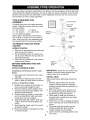
Warranty ................................................
Safety Rules ..........................................
Product Specifications
...........................
Assembly/Pre-Operation
.......................
Operation .............................................
2
3
6
8
11
Maintenance
Maintenance
Schedule ........................
........................................
17
17
Service and Adjustments
.....................
Storage ................................................
Troubleshooting
...................................
Repair Parts .........................................
21
27
28
32
Murray, Inc. warrants to the original purchaser
that this unit shall be free from defects in
material and workmanship
under normal use and service for a period of Two (2) Years
from the date of purchase; however, this warranty does not cover engines, accessories
such as snow blowers, snow blades, grass baggers and plows), transmissions,
batteres and Normal Wear Parts (except as noted below) or transaxles
as the companies
that
manufacture
these items furnish their own warranties and provide service through their
authorized
field service facilities.
For additional information,
see the warranties
covering these particular
parts. If you are uncertain whether your unit contains or is equipped
with one or more of these parts, consult your dealer prior to purchase.
Subject to the
terms and conditions noted in this Limited Warranty, we shall, at our option, repair or
replace at no cost to the original purchaser
any part covered by this Limited Warranty
during the applicable warranty period.
In the event the battery proves defective within ninety (90) days from the date of purchase, we will replace it without charge.
If the battery proves defective after (90) days
but within one hundred twenty (120) days from the date of purchase, we will replace it for
a charge of one half (1/2) of the retail price of the battery in effect at the time of return.
Normal Wear Parts are defined as belts, blades, blade adapters, pneumatic tires, headlights and seat covers. These parts are warranted
to be free of defects in material and
workmanship
as delivered with the product. Any claim for repair or replacement
of Normal Wear Parts must be made within thirty (30) days of the date of purchase.
No claims
involving damage caused from material use, abuse or misuse will be honored.
This Murray, Inc. Two (2) Year Limited
Warranty
is your exclusive remedy; however,
this warranty is void or does not apply to any unit that has been tampered with, altered,
misused, abused or used for rental or other commercial
and/or professional
(non-homeowner) uses. Your warranty does not cover minor mechanical
adjustments
which are
not due to any defect in material or workmanship.
For assistance
in making such adjustments, consult your Instruction
Book.
To make a claim under this Murray, Inc. Two (2) Year Limited
Warranty,
return the unit
(or if authorized
in advance, the defective part) along with your proof of purchase to an
Authorized
Service Center near you. To locate the nearest Authorized
Service Center,
call the Central Parts Distributor for your area shown in the list provided with your unit or
check the Yellow Page listings in your local telephone
directory.
If you return the entire
unit, we will repair the unit. If we authorize the return of the defective part only, we will
either replace or repair the part. In the case of a defect in a transmission
or differential (as distinguished
from a transaxle),
the entire transmission
or differential
must be
returned since they do not include user serviceable
parts.
This Murray, Inc. Two (2) Year Limited
Warranty
gives you specific legal rights, and
you .may also have other rights which vary from state to state. This Limited
Warranty
is given in lieu of all other expressed
and implied warranties
including
the implied
warranty
of merchantability
and warranty
of fitness for a particular
purpose.
If you
need additional information
on this written warranty or assistance
in obtaining service,
call or write to the address below. The model number along with the CUSTOMER
CARE
Center 1-800 number is on the Model Number Nameplate attached to the unit.
MURRAY, INC.
Outdoor Power Equipment
Customer Service Department
P.O. Box 268
Brentwood,
Tennessee
37027
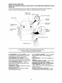
This instruction bookis written for a person
with somemechanicalability.Likemostservice books, not all the steps are described.
Steps on how to loosen or tighten fasteners are steps anyone can follow with some
mechanical ability. Read and follow these
instructionsbeforeyou use the unit.
Know your product: If you understandthe
unitandhowthe unitoperates,youwillgetthe
bestperformance.As you readthis manual,
comparethe illustrationsto the unit. Learn
the locationandthe functionof the controls.
Tohelp preventan accident,followthe operatinginstructionsandthe safetyrules. Keep
this manualfor future reference.
IMPORTANT:Manyunitsarenotassembled
andaresoldincartons. Itis theresponsibility
of the ownerto makesure the assembly instructionsinthe manualareexactlyfollowed.
Other units are purchased in assembled
condition. On assembledunits, it is the responsibility of the owner to make sure the
unit is correctlyassembled.The ownermust
carefully checkthe unit accordingto the instructionsinthis manualbeforeitisfirst used.
RESPONSIBILITY
OF THE OWNER
The responsibility of the owner is to
follow the instructions below.
1. Carefully read and follow the rules for
safe operation.
2. Follow all the assembly and preparation instructions.
3.
4.
5.
6.
7.
8.
Inspect the unit.
Make sure that the operator of the unit
knows how to correctly use all standard and accessory
equipment.
Operate the unit only with guards,
shields, and other safety items in place
and working correctly.
Correctly adjust the unit.
Service the unit only with authorized
or
approved replacement
parts.
Complete all maintenance
on the unit.
IMPORTANT: This cutting machine is capable of amputating hands and feet and throwing objects. Failure to observe the following safety instructions could result in serious
injury or death.
WARNING:
In order to prevent
WARNING:
Battery posts, terminals
and related accessories
contain lead and
lead compounds,
chemicals
known to the
State of California to cause cancer and
accidental starting when setting up,
transporting,
adjusting or making repairs,
always disconnect
spark plug wire and
place wire where it cannot contact spark
plug.
WARNING:
hill in neutral,
tractor.
WARNING:
birth defects or other reproductive
Wash hands after handling.
Do not coast down a
you may lose control
I. GENERAL
OPERATION
• Read, understand, and followall
instructions on the machine and in the
manual before starting.
• Do not put hands or feet near rotating
parts or under the machine. Keep clear
of the discharge opening at all times.
• Only allow responsible adults, who are
familiar with the instructions, to operate
the machine.
• Clear the area of objects such as
rocks, toys, wire, etc., which could be
picked up and thrown by the blades.
• Be sure the area is clear of bystanders before operating. Stop machine if
anyone enters the area.
• Never carry passengers.
• Do not mow in reverse unless absolutely necessary. Always look down
and behind before and while backing.
of the
Tow only the attach-
ments that are recommended
by and
comply with specifications
of the manufacturer of your tractor. Use common
sense when towing. Operate only at the
lowest possible speed when on a slope.
Too heavy of a load, while on a slope, is
dangerous.
Tires can lose traction with
the ground and cause you to lose control
of your tractor.
WARNING:
Engine
exhaust,
harm.
some
of its constituents,
and certain vehicle
components
contain or emit chemicals
known to the State of California to cause
cancer and birth defects or other reproductive harm.
3
•
•
•
•
•
•
•
•
•
•
•
•
•
Never direct discharged
material
toward anyone. Avoid discharging
material against a wall or obstruction.
Material may ricochet back toward the
operator. Stop the blades when crossing gravel surfaces.
Do not operate machine without the
entire grass catcher, discharge
guard,
or other safety devices in place and
working.
Slowdown
before turning.
Never leave a running machine
unattended.
Always turn off blades,
set parking brake, stop engine, and
remove keys before dismounting.
Disengage
blades when not mowing.
Shut off engine and wait for all parts to
come to a complete stop before cleaning the machine, removing the grass
catcher, or unclogging
the discharge
guard.
Operate machine only in daylight or
good artificial light.
Do not operate the machine while
under the influence of alcohol or drugs.
Watch for traffic when operating near
or crossing roadways.
Use extra care when loading or unloading the machine into a trailer or truck.
Always wear eye protection when operating machine.
Data indicates that operators, age 60
years and above, are involved in a
large percentage
of riding mower-related injuries. These operators should
evaluate their ability to operate the
riding mower safely enough to protect
themselves
and others from serious
injury.
Follow the manufacturer's
recommendation for wheel weights or counterweights.
Keep machine free of grass, leaves or
other debris build-up which can touch
hot exhaust / engine parts and burn.
Do not allow the mower deck to plow
leaves or other debris which can cause
build-up to occur. Clean any oil or fuel
spillage before operating or storing the
machine. Allow machine to cool before
storage.
II. SLOPE
OPERATION
Slopes are a major factor related to loss of
control and tip-over accidents, which can
result in severe injury or death. Operation on all slopes requires extra caution.
If
you cannot back up the slope or if you feel
uneasy on it, do not mow it.
•
Mow up and down slopes, not across.
•
Watch for holes, ruts, bumps, rocks, or
other hidden objects.
Uneven terrain
could overturn the machine.
Tall grass
can hide obstacles.
•
Choose a low ground speed so that
you will not have to stop or shift while
on the slope.
•
Do not mow on wet grass.Tires
may
lose traction.
Always keep the machine in gear when
going down slopes. Do not shift to
neutral and coast downhill.
•
•
•
•
•
Avoid starting, stopping, or turning on
a slope. If the tires lose traction,
disengage the blades and proceed slowly
straight down the slope.
Keep all movement
on the slopes slow
and gradual.
Do not make sudden
changes in speed or direction, which
could cause the machine to roll over.
Use extra care while operating machine with grass catchers or other attachments;
they can affect the stability
of the machine. Do no use on steep
slopes.
Do not try to stabilize the machine by
putting your foot on the ground.
Do not mow near drop-offs, ditches,
or embankments.
The machine could
suddenly roll over if a wheel is over the
edge or if the edge caves in.
III. CHILDREN
Tragic accidents
can occur if the operator
is not alert to the presence
of children.
Children are often attracted to the machine
and the mowing
activity.
that children
will remain
saw them.
•
•
•
Never assume
where you last
Keep children out of the mowing area
and in the watchful care of a responsible adult other than the operator.
Be alert and turn machine off if a child
enters the area.
Before and while backing, look behind
and down for small children.
•
•
•
•
Nevercarry children,evenwith the
bladesshut off. They may fall off and
be seriously injuredor interferewith
safe machineoperation.Children who
havebeen given rides in the past may
suddenlyappearin the mowingarea
for another ride and be run over or
backedover by the machine.
Neverallow childrento operate the
machine.
Use extra care when approachingblind
corners,shrubs, trees,or other objects
that may blockyour view of a child.
•
•
•
IV. TOWING
• Tow only with a machine that has a
hitch designed for towing. Do not attach towed equipment except at the
hitch point.
• Followthe manufacturer's recommendation for weight limits for towed equipment and towing on slopes.
• Never allow children or others in or on
towed equipment.
• On slopes, the weight of the towed
equipment may cause loss of traction
and loss of control.
• Travel slowly and allow extra distance
to stop.
GENERAL
•
•
•
•
•
V. SERVICE
SAFE
HANDLING
OF
GASOLINE
•
To avoid personal injury or property
damage, use extreme care in handling
gasoline. Gasoline is extremely flammable
and the vapors are explosive.
•
Extinguish all cigarettes,
cigars, pipes,
and other sources of ignition.
•
Use only approved gasoline container.
•
Never remove gas cap or add fuel with
the engine running. Allow engine to
cool before refueling.
•
Never fuel the machine indoors.
•
Never store the machine or fuel con-
•
Remove gas-powered
equipment
from
the truck or trailer and refuel it on the
ground. If this is not possible, then
refuel such equipment
with a portable
container, rather than from a gasoline
dispenser
nozzle.
Keep the nozzle in contact with the rim
of the fuel tank or container opening at
all times until fueling is complete.
Do
not use a nozzle lock-open
device.
If fuel is spilled on clothing, change
clothing immediately.
Never overfill fuel tank. Replace gas
cap and tighten securely.
•
•
•
•
tainer where there is an open flame,
spark, or pilot light such as on a water
heater or other appliances.
Never fill containers inside a vehicle
or on a truck or trailer bed with plastic
liner. Always place containers
on the
ground away from your vehicle when
filling.
5
SERVICE
Never operate machine in a closed
area.
Keep all nuts and bolts tight to be sure
the equipment
is in safe working condition.
Never tamper with safety devices.
Check their proper operation regularly.
Keep machine free of grass, leaves, or
other debris build-up.
Clean oil or fuel
spillage and remove any fuel-soaked
debris. Allow machine to cool before
storing.
If you strike a foreign object, stop and
inspect the machine. Repair, if necessary, before restarting.
Never make any adjustments
or repairs
with the engine running.
Check grass catcher components
and
the discharge
guard frequently
and
replace with manufacturer's
recommended parts, when necessary.
Mower blades are sharp. Wrap the
blade or wear gloves, and use extra
caution when servicing them.
Check brake operation frequently.
Adjust and service as required.
Maintain or replace safety and instruction labels, as necessary.
•
•
•
•
•
Be sure the area is clear of bystanders before operating.
Stop machine if
anyone enters the area.
Never carry passengers.
Do not mow in reverse unless absolutely necessary. Always look down
and behind before and while backing.
Never carry children, even with the
blades shut off. They may fall off and
be seriously injured or interfere with
safe machine operation. Children who
have been given rides in the past may
suddenly appear in the mowing area
for another ride and be run over or
backed over by the machine.
Keep children out of the mowing area
and in the watchful care of a responsible adult other than the operator.
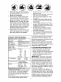
PRODUCT
SPECIFICATIONS
Gasoline Capacity
and Type:
1.25 Unleaded
Regular
Oil Type
API-SG-SL):
SAE 30 (above 32°F)
SAE 5W-30(below 32°F
Oil Capacity:
3 Pints
Spark
(Gap:
Champion
Plug:
.030")
Tire Pressure:
Front:
Rear:
14 PSI
10 PSI
Charging
3 Amps
5 Amps
System:
Battery:
Blade
Battery
Headlights
Amp/Hr:
Min. CCA:
Case Size:
Bolt Torque:
•
Before and while backing, look behind
and down for small children.
Mow up and down slopes (15 ° Max),
not across.
Choose a low ground speed so that
you will not have to stop or shift while
on the slope.
Avoid starting, stopping, or turning on
a slope. If the tires lose traction,
disengage the blades and proceed slowly
straight down the slope.
If machine stops while going uphill,
disengage
blades, shift into reverse
and back down slowly.
Do not turn on slopes unless necessary, and then, turn slowly and gradually downhill, if possible.
•
•
•
•
•
27-35
off if a child
your nearest authorized
service center/
department
We have competent,
welltrained technicians
and the proper tools to
service or repair this tractor.
Please read and retain this manual. The
instructions
will enable you to assemble
and maintain your tractor properly.
Always
observe the "SAFETY RULES".
CUSTOMER
1.2
2.4
3.5
4.8
5.3
1.5
Speed
Be alert and turn machine
enters the area.
RC12YC
Forward:
1st
2nd
3rd
4th
5th
Reverse:
Ground
(MPH):
•
28
230
U1R
Ft. Lbs.
CONGRATULATIONS
on your purchase
of a new tractor. It has been designed,
engineered
and manufactured
to give
you the best possible dependability
and
performance.
Should you experience
any problem you
cannot easily remedy, please contact
RESPONSIBILITIES
• Read and observe the safety rules.
• Follow a regular schedule in maintaining, caring for and using your tractor.
• Follow the instructions
under"Maintenance" and "Storage" sections of this
owner's manual.
_L, WARNING:
This tractor is equipped
with an internal combustion
engine and
should not be used on or near any unimproved forest-covered,
brush-covered
or
grass-covered
land unless the engine's
exhaust system is equipped with a spark
arrester meeting applicable
local or state
laws (if any). If a spark arrester is used, it
should be maintained
in effective working
order by the operator.
In the state of California the above is required by
nia Public
may have
on federal
muffler is
authorized
law (Section 4442 of the CaliforResources
Code). Other states
similar laws. Federal laws apply
lands. A spark arrester for the
available through your nearest
service center/department.
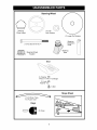
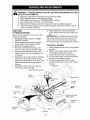
Steering Wheel
Steering
Wheel Insert
(1) 5/16
Lock Washer
(1) Large Flat Washer
Extension
Shaft
(1) Hex Bolt 5/16-18 x4
_
_]
,
_
b
Steering Wheel
,
Adapter
Steering
Boot
Steering
,._j
Seat
(1) Washer @
17/32 x 1-3/16 x 12 Gauge
(1) Lock
Washer 1/2
_(1
) Bolt
Slope Sheet
(1) Oil Drain Tube
For Future Use
Keys
(2) Keys
7
Your new tractor has been assembled
at the factory with the exception of those parts left
unassembled
for shipping purposes. To ensure safe and proper operation of your tractor
all parts and hardware you assemble must be tightened securely. Use the correct tools
as necessary
to insure proper tightness.
TOOLS REQUIRED
ASSEMBLY
Insert
FOR
5/16 Hex Bolt
A socket wrench set will make assembly
easier. Standard wrench sizes you need
are listed below.
(1) 3/4"wrench
(1) Pliers
(1) 1/2" wrench
(1) Utility knife
(1) Tire pressure gauge
When right or left hand is mentioned in
this manual, it means, from your point of
view, when you are in the operating position (seated behind the steering wheel).
Lock
Washer
Large Flat
...... so J
-_\
Steering
Wheel
Washer
)
/
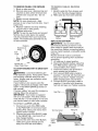
TO REMOVE TRACTOR
FROM
CARTON
UNPACK CARTON
1. Remove all accessible loose parts and
parts boxes from carton.
2. Cut along dotted lines on all four panels of carton. Remove end panels and
lay side panels flat.
3. Check for any additional loose parts or
cartons and remove.
Steering
Shaft
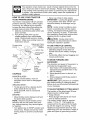
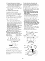
BEFORE REMOVING
TRACTOR
FROM SKID
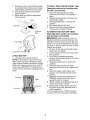
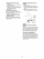
ATTACH STEERING WHEEL
Slots
ASSEMBLE EXTENSION SHAFT AND
BOOT
1. Slide extension shaft onto lower steering shaft.
2. Place tabs of steering boot over tab
slots in dash and push down to secure.
INSTALL STEERING
WHEEL
3. Position front wheels of the tractor
so
they are pointing straight forward.
4. Remove steering wheel adapter from
steering wheel and slide adapter onto
steering shaft extension.
5. Position steering wheel so cross bars
are horizontal
(left to right) and slide
inside boot and onto adapter.
6. Assemble
large flat washer, 5/16 lock
washer, 5/16 hex bolt and tighten securely.
7. Snap steering wheel insert into center
of steering wheel.
8. Remove protective materials from tractor hood and grill.
IMPORTANT: Check for and remove any
staples in skid that may puncture tires
where tractor is to roll off skid.
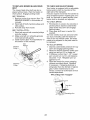
INSTALL
SEAT
Adjust seat
knob.
1. Remove
washer
packing
seat to
before
tightening
adjustment
adjustment
knob and flat
securing seat to cardboard
and set aside for assembly
tractor.
of
2.
Pivot seat upward and remove from
the cardboard packing. Remove the
cardboard packing and discard.
3. Place seat on seat pan so head of
shoulder bolt is positioned
over large
slotted hole in pan.
4. Push down on seat to engage shoulder
bolt in slot and pull seat towards rear of
tractor.
5.
6.
Pivot seat and pan forward and assemble adjustment
knob and flat
washer loosely. Do not tighten.
Lower seat into operating position and
sit in seat.
7. Slide seat until a comfortableposition
is reachedwhich allowsyou to press
clutch/brakepedal all the way down.
8. Get off seat without movingits adjusted position.
9. Raise seat and tighten adjustment
knob securely.
TO ROLL
Operation
TRACTOR
section
OFF
for
SKID
location
(See
and
function
of controls)
1. Press lift lever plunger and raise
attachment
lift lever to its highest position.
2. Release parking brake by depressing
clutch/brake
pedal.
3. Place gearshift lever in neutral (N)
position.
4. Roll tractor forward off skid.
Seat
Seat
5.
Remove banding holding deflector
shield guard up against tractor.
TO DRIVE
Bolt
TRACTOR
(See Operation
section
OFF
for
SKID
location
and function
of controls)
AI_WARNING:
Before starting, read, understand and follow all instructions
in the
Flat Washer
Operation section of this manual. Be sure
tractor is in a well-ventilated
area. Be sure
the area in front of tractor is clear of other
people and objects.
1. Be sure all the above assembly steps
have been completed.
2. Check engine oil level and fill fuel tank
with gasoline.
3. Sit on seat in operating position,
depress clutch/brake
pedal and set the
parking brake.
4. Place gear shift lever in neutral (N)
position.
5. Press lift lever plunger and raise
attachment
lift lever to its highest position.
\
Adj
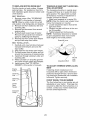
CHECK
BATTERY
1. Lift seat pan to raised position.
NOTE: If this battery is put into service
after month and year indicated on label
(label located between terminals)
charge
battery for minimum of one hour at 6-10
amps. (See "BATTERY"
in Maintenance
section of this manual for charging instructions).
6.
Start the engine. After engine has
started, move throttle control to idle
position.
7. Depress clutch/brake
pedal into full
"BRAKE" position and hold. Move
gearshift lever to 1st gear.
8. Slowly release clutch/brake
pedal and
slowly drive tractor off skid.
9. Apply brake to stop tractor, set parking brake and place gearshift lever in
neutral position.
10. Turn ignition key to "STOP" position.
Continue with the instructions
that follow.
Seat
Terminal
9
CHECK
TIRE
PRESSURE
J CHECKL
IS T
The tires on your tractor were overinflated at the factory for shipping purposes.
Correct tire pressure is important for best
cutting performance.
• Reduce tire pressure to PSI shown in
"PRODUCT SPECIFICATIONS" section
of this manual.
Before you operate your new tractor, we
wish to assure that you receive the best
performance
and satisfaction
from this
Quality Product.
Please review the following checklist:
,/All assembly
instructions
have been
completed.
CHECK FOR PROPER
OF ALL BELTS
,/No
POSITION
DECK
LEVELNESS
CHECK
BRAKE
section
parts in carton.
,/All tires are properly inflated.
(For shipping purposes, the tires were overinflated at the factory).
,/Be sure mower deck is properly leveled
side-to-side/front-to-rear
for best cutting
results. (Tires must be properly inflated
for leveling).
¢" Check mower and drive belts. Be sure
For best cutting results, mower housing
should be properly leveled. See "TO LEVEL MOWER HOUSING"
in the Service
and Adjustments
loose
,/Battery
is properly prepared and
charged.
(Minimum
1 hour at 6 amps).
,/Seat
is adjusted comfortably
and tightened securely.
See the figures that are shown for replacing motion and mower blade drive belts
in the Service and Adjustments section
of this manual. Verify that the belts are
routed correctly.
CHECK
remaining
of this manual.
SYSTEM
they are routed properly around
and inside all belt keepers.
After you learn how to operate your tractor, check to see that the brake is properly
adjusted. See "TO ADJUST BRAKE" in
the Service and Adjustments section of
this manual.
pulleys
¢" Check wiring.
See that all connections
are still secure and wires are properly
clamped.
While learning how to use your tractor, pay
extra attention to the following important
items:
¢" Engine oil is at proper level.
¢" Fuel tank is filled with fresh, clean, regular unleaded gasoline.
¢" Become familiar with all controls, their
location and function.
Operate them
before you start the engine.
¢" Be sure brake system is in safe operating condition.
¢" Be sure Operator Presence System
and Reverse Operation System (ROS)
are working properly (See the Operation and Maintenance
sections in this
manual).
10
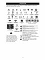
These symbols may appear on your tractor
Learn and understand
their meaning.
R
N
H
L
REVERSE
NEUTRAL
HIGH
LOW
or in literature
supplied
with the product.
I',,I
CHOKE
SLOW
FAST
IGNITION SWITCH
6
ENGINE OFF
REVERSE
OPERATION
SYSTEM (ROS)
ENGINE ON
ENGINE START
PARKING
BRAKE
@
PARKING BRAKE
LOCKED
PARKING BRAKE
UNLOCKED
t
OVER TEMP
LIGHT
FUEL
OIL PRESSURE
BATTERY
REVERSE
FORWARD
MOWER
HEIGHT
MOWER
LIFT
m
ATTACHMENT
CLUTCH DISENGAGED
ATTACHMENT
CLUTCH ENGAGED
BRAKE/CLUTCH
PEDAL
KEEP AREA CLEAR
SLOPE HAZARDS
(SEE SAFETY RULES SECTION)
DANGER
will result indicates
in death aorhazard
seriouswhich,
injury.if not avoided,
LIGHTS ON
WARNING
hazard
which,
if not avoided,
could result indicates
in death a or
serious
injury.
FREE WHEEL
(Automatic
Models only)
&
CAUTION indicates a hazard which, if not avoided,
might result in minor or moderate injury.
DANGER, KEEP HANDS
AND FEET AWAY
CAUTION when used without the alert symbol,
indicates a situation that could result in damage
to the tractor and/or engine.
Failure to follow instructions
could result in serious injury or
death. The safety alert symbol
is used to identify safety information about hazards which can
result in death, serious injury
and/or property damage.
,l_{ll/ll/_l_/.,
HOT SURFACES indicates a hazard which,
if not avoided, could result in death, serious
and/or property damage.
FIRE indicates a hazard which, if not avoided,
could result in death, serious injury and/or
property damage.
11
injury
KNOW YOUR TRACTOR
READ THIS OWNER'S MANUAL AND SAFETY RULES BEFORE OPERATING YOUR
TRACTOR
Compare the illustrations with your tractor to familiarize yourself with the locations of
various controls and adjustments. Save this manual for future reference.
Attachment
Clutch Lever
Ignition Switch
"ON" Position
Light Switch
Lift Lever
Throttle/Choke
Control
Pedal
_gBrake Lever
Gearshift Lever
Our tractors conform to the safety standards of the
American
National Standards
Institute.
ATTACHMENT
CLUTCH
LEVER
- Used
LIFT
to engage the mower blades, or other attachments
mounted to your tractor.
ATTACHMENT
LIFT LEVER - Used to
LEVER
PLUNGER
- Used to release
attachment
lift lever when changing its
position.
LIGHT SWITCH - Turns the headlights
on
and off.
PARKING
BRAKE LEVER - Locks clutch/
raise, lower, and adjust the mower deck or
other attachments
mounted to your tractor.
CLUTCH/BRAKE
PEDAL - Used for
brake pedal into the brake position.
REVERSE
OPERATION
SYSTEM (ROS)
"ON" POSlTON - Allows operation of
mower deck or other powered attachment
while in reverse.
THROTTLE/CHOKE
CONTROL
- Used
declutching
and braking the tractor and
starting the engine.
GEARSHIFT
LEVER - Selects the speed
and direction of tractor.
IGNITION SWITCH
- Used for starting
and stopping the engine.
for starting
12
and controlling
engine
speed.
The operation of any tractor can result in foreign objects thrown into the
eyes, which can result in severe eye damage.
Always wear safety glasses
or eye shields while operating your tractor or performing
any adjustments
or repairs. We recommend
a wide vision safety mask over spectacles
or
standard safety glasses.
HOW
TO USE
YOUR
TO SET PARKING
TRACTOR
• Never use choke to stop engine.
IMPORTANT:
Leaving the ignition switch
in any position other than "STOP" will
cause the battery to discharge
and go
dead.
NOTE:
Under certain conditions when
BRAKE
Your tractor is equipped with an operator
presence sensing
switch. When engine
is running, any attempt by the operator
to leave the seat without first setting the
parking brake will shut off the engine.
1. Depress clutch/brake
pedal all the way
down and hold.
2.
tractor is standing idle with the engine
running, hot engine exhaust gases may
cause "browning" of grass. To eliminate
this possibility, always stop engine when
stopping tractor on grass areas.
Pull parking brake lever up and
release pressure from clutch/brake
pedal. Pedal should remain in brake
position.
Make sure parking brake will
hold tractor secure.
,_CAUTION:
TO USE THROTTLE
gaged"
Position
• Full throttle offers the best bagging
mower performance.
Position
TO MOVE
BLADES
-
3.
Slowly release clutch/brake
pedal to
start movement.
IMPORTANT:
Bring tractor to a complete
stop before shifting or changing gears.
Failure to do so will shorten the useful life
• To stop mower blades, move attachment clutch lever to disengaged
position.
GROUND
DRIVE
-
of your transaxle.
• To stop ground drive, depress clutch/
brake pedal all the way down.
• Move gearshift
lever to neutral (N)
position.
ENGINE
• Move throttle
control
AND
The direction and speed of movement
is
controlled
by the gearshift
lever.
1. Start tractor with clutch/brake
pedal
depressed
and gearshift lever in neutral (N) position.
2. Move gearshift lever to desired
position.
Parking
Brake
"Engaged"
Position
STOPPING
MOWER
FORWARD
and
BACKWARD
Gearshift
Lever
"Disengaged"
Position
CONTROL
Always operate engine at full throttle.
• Operating engine at less than full
throttle reduces the battery charging
rate.
nition Key
Clutch/
Brake
Pedal
stop tractor
completely,
as described
above, before
leaving the operator's position.
Attachment Clutch
Lever "Engaged"
Position
Throttle/Choke
Control
Always
between
TO ADJUST
MOWER
CUTTING
HEIGHT
The position of the attachment
lift lever
determines
the cutting height.
• Grasp lift lever.
• Press plunger with thumb and move
lever to desired position.
The cutting height range is approximately 1-1/2 to 4". The heights are
measured from the ground to the blade
tip with the engine not running. These
heights are approximate
and may vary
depending
upon soil conditions,
height of
grass and types of grass being mowed.
half and
full speed (fast) position.
NOTE:
Failure to move throttle control
between half and full speed (fast) position, before stopping, may cause engine
to "backfire".
• Turn ignition key to "STOP" position and
remove key. Always remove key when
leaving tractor to prevent unauthorized
use.
13
• The average lawn should be cut to approximately
2-1/2 inches during the cool
season and to over 3 inches during hot
months.
For healthier and better look-
REVERSE
ing lawns, mow often and after moderate growth.
• For best cutting performance,
grass
over 6 inches in height should be
mowed twice. Make the first cut relatively high; the second
TO OPERATE
to desired
,41_WARNING:
SYSTEM
(ROS)
Backing
up with the at-
tachment clutch engaged while mowing
is strongly discouraged.
Turning the ROS
"ON", to allow reverse operation with the
attachment
clutch engaged, should only
be done when the operator decides it is
necessary
to reposition the machine with
the attachment
engaged. Do not mow in
reverse
unless absolutely
necessary.
height.
MOWER
Your tractor is equipped with an operator
presence sensing switch. Any attempt
by the operator to leave the seat with the
engine running and the attachment
clutch
engaged will shut off the engine. You must
remain fully and centrally positioned
in the
seat to prevent the engine from hesitating
or cutting off when operating your equipment on rough, rolling terrain or hills.
1. Select desired height of cut.
2. Start mower blades by engaging attachment
clutch control.
USING THE REVERSE
SYSTEM -
TO STOP MOWER BLADES disengage attachment clutch control.
_II, CAUTION: Do not operate the mower
without either the entire grass catcher,
on mowers so equipped, or the deflector
shield in place.
Depress clutch/brake
down and hold.
2.
With engine running, turn ignition key
counterclockwise
to ROS "ON" position.
3.
4.
Look down and behind before backing.
Move gear shift lever to reverse (R) position and slowly release clutch/brake
pedal to start movement.
When use of the ROS is no longer
needed, turn the ignition key clockwise
to engine "ON" position.
ROS "ON" Position
Attachemnt
Lift Lever
High Position
Low
Position
gaged"
\ Deflector
Shield
14
OPERATION
1.
5.
Attachment Clutch Lever
"Engaged" Position
_,'_'
OPERATION
Your tractor is equipped with a Reverse
Operation System (ROS). Any attempt by
the operator to travel in the reverse direction with the attachment
clutch engaged
will shut off the engine unless ignition key
is placed in the ROS "ON" position.
pedal all the way
Engine "ON" Position
(Normal Operating)
TO OPERATE
ON HILLS
BEFORE
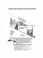
_I:_WARNING:
Do not drive up or down
hills with slopes greater than 15 ° and do
not drive across any slope. Use the slope
guide provided at the back of this manual.
• Choose the slowest speed before starting up or down hills.
• Avoid stopping or changing speed on
hills.
CHECK
ADD
AND
OTHER
GASOLINE
• Fill fuel tank to bottom
position
of filler neck. Do
not overfill. Use fresh, clean, regular
unleaded gasoline with a minimum of
87 octane. (Use of leaded gasoline will
increase carbon and lead oxide deposits
and reduce valve life). Do not mix oil
with gasoline.
Purchase fuel in quantities that can be used within 30 days to
assure fuel freshness.
_CAUTION:
Wipe off any spilled oil or
fuel. Do not store, spill or use gasoline
near an open flame.
IMPORTANT:
When operating in temperatures below32°F(0°C),
use fresh, clean
winter grade gasoline to help insure good
cold weather starting.
CAUTION:
Alcohol blended fuels (called
gasohol or using ethanol or methanol)
can
attract moisture which leads to separation and formation of acids during storage.
Acidic gas can damage the fuel system
of an engine while in storage. To avoid
engine problems, the fuel system should
be emptied before storage of 30 days
or longer. Drain the gas tank, start the
engine and let it run until the fuel lines
and carburetor
are empty. Use fresh fuel
next season.
See Storage Instructions
for
additional information.
Never use engine
or carburetor
cleaner products in the fuel
tank or permanent
damage may occur.
• When pushing or towing your tractor,
be sure gearshift lever is in neutral (N)
position.
• Do not push or tow tractor at more than
five (5) MPH.
NOTE: To protect hood from damage
when transporting
your tractor on a truck
or a trailer, be sure hood is closed and
secured to tractor. Use an appropriate
means of tying hood to tractor (rope, cord,
etc.).
CARTS
ENGINE
nance section of this manual).
• To change engine oil, see the Maintenance section in this manual.
TO TRANSPORT
TOWING
MENTS
THE
OIL LEVEL
The engine in your tractor
has been
shipped, from the factory, already filled
with summer weight oil.
1. Check engine oil with tractor on level
ground.
2. Remove oil fill cap/dipstick
and wipe
clean, reinsert the dipstick and screw
cap tight, wait for a few seconds, remove and read oil level. If necessary,
add oil until "FULL" mark on dipstick is
reached.
Do not overfill.
• For cold weather operation you should
change oil for easier starting (See "OIL
VISCOSITY
CHART" in the Mainte-
• If slowing is necessary,
move throttle
control lever to slower position.
• If stopping is absolutely
necessary, push
clutch/brake
pedal quickly to brake position and engage parking brake.
• Move gearshift
lever to 1st gear. Be
sure you have allowed room for tractor
to roll slightly as you restart movement.
• To restart movement,
slowly release
parking brake and clutch/brake
pedal.
• Make all turns slowly.
• Raise attachment
lift to highest
with attachment
lift control.
STARTING
ENGINE
ATTACH-
Tow only the attachments
that are recommended by and comply with specifications
of the manufacturer
of your tractor. Use
common sense when towing. Too heavy
of a load, while on a slope, is dangerous.
Tires can lose traction with the ground and
cause you to lose control of your tractor.
15
TO START
ENGINE
MOWING
TIPS
• Tire chains cannot be used when the
mower housing is attached to tractor.
• Mower should be properly leveled for
best mowing performance.
See "TO
LEVEL MOWER HOUSING"
in the
Service and Adjustments
section of this
manual.
• The left hand side of mower should be
used for trimming.
• Drive so that clippings are discharged
onto the area that has already been
cut. Have the cut area to the right of
the tractor. This will result in a more
even distribution
of clippings and more
uniform cutting.
• When mowing large areas, start by
turning to the right so that clippings will
discharge
away from shrubs, fences,
driveways, etc. After one or two rounds,
mow in the opposite direction making
left hand turns until finished.
When starting the engine for the first time
or if the engine has run out of fuel, it will
take extra cranking time to move fuel from
the tank to the engine.
1. Sit on seat in operating position,
depress clutch/brake pedal and set
parking brake.
2. Place gear shift lever in neutral (N)
position.
3. Move attachment clutch to disengaged
position.
4. Move throttle control to choke position.
NOTE: Before starting, read the warm
and cold starting procedures below.
5. Insert key into ignition and turn key
clockwise to start position and release
key as soon as engine starts. Do
not run starter continuously for more
than fifteen seconds per minute. If the
engine does not start after several
attempts, move throttle control to fast
position, wait a few minutes and try
again. If engine still does not start,
move the throttle control back to the
choke position and retry.
WARM
above)
WEATHER
STARTING
d-
(50 ° F and
6.
When engine starts, move the throttle
control to the fast position.
• The attachments
and ground drive can
now be used. If the engine does not
accept the load, restart the engine and
allow it to warm up for one minute using
the choke as described
above.
COLD WEATHER
below)
STARTING
(
,
)
• If grass is extremely tall, it should be
mowed twice to reduce load and possible fire hazard from dried clippings.
Make first cut relatively high; the second
to the desired height.
• Do not mow grass when it is wet.
Wet grass will plug mower and leave
undesirable
clumps.
Allow grass to dry
before mowing.
• Always
operate engine at full throttle
when mowing
to assure better mowing performance
and proper discharge
of material.
Regulate ground speed by
selecting a low enough gear to give the
mower cutting performance
as well as
the quality of cut desired.
• When operating attachments,
select a
ground speed that will suit the terrain
and give best performance
of the attachment
being used.
( 50 ° F and
6.
When engine starts, leave throttle
control in choke position until engine
warms up and begins to run roughly.
Once rough running begins, immediately move the throttle control to the
fast position. Engine warm-up may
take from several seconds to several
minutes (the colder the temperature,
the longer the warm-up).
• The attachments
can also be used dur-
ing the engine warm-up period.
NOTE:
If at a high altitude (above 3000
feet) or in cold temperatures
(below 32 F)
the carburetor fuel mixture may need to
be adjusted for best engine performance
(see "TO ADJUST CARBURETOR"
in the
Service and Adjustments
section of this
manual).
16
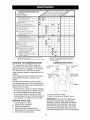
ASOUCOM
PLE
TE
REGULAR
T
R
......
SERVICE
/_q_/'%qy_'_"
_hh;;kk
T_irr_rO_ae_i
°n
_
Check Operator
ROS Systems
I_
Presence
If
1_5
A
Sharpen/Replace
C
Lubrication
0
Check Battery
Level
1_4
Clean Battery
and Terminals
_
R
Blades
I_
if
Cooling
Check V-Belts
Check Engine
If
Oil Level
_
Change
Engine
Oil (with oil filter)
E
Change
Engine
Oil (without
N
Clean Air
G
Clean Air Screen
Inspect
E
11_'1,2
oil filter)
_1_1,2
_111_
2
1_2
Arrester
Oil Filter (If equipped)
Clean Engine
Cooling
1_1,2
Fins
Spark
Plug
Replace
Air Filter Paper Cartridge
Replace
Fuel Filter
1 - Change more often when operating
in high ambient
temperatures.
2 - Service more often when operating
If
under
a heavy
load
in dirty or dusty
or
3 - Replace
blades more often when mowing
in sandy soil.
4 - Not required
if equipped
with maintenance-free
battery.
5 - Tighten front axle pivot bolt to 35 ft.-Ibs, maximum.
Do not overtighten.
conditions,
LUBRICATION
RECOMMENDATIONS
Spindle
Zerk
CHART
--
,_Jr
_Front Wheel
Bearing
Zerk
• At least once a year you should replace
the spark plug, clean or replace air filter,
and check blades and belts for wear.
_ Spindle
Zerk
: _Front Wheel
Bearing Zerk
_
A new spark plug and clean air filter
assure proper air-fuel mixture and help
your engine run better and last longer.
EACH
I_
11_2
The warranty on this tractor does not
cover items that have been subjected to
operator abuse or negligence.
To receive
full value from the warranty, operator
must maintain tractor as instructed
in this
manual.
Some adjustments
will need to be made
periodically
to properly maintain your
tractor.
At least once a season, check to see if
you should make any of the adjustments
described
in the Service and Adjustments
section of this manual.
BEFORE
2
I_
Replace
GENERAL
I_
Filter
Muffler/Spark
Replace
if
11_3
Chart
Check Transaxle
DATES
and
Check for Loose Fasteners
Mower
SERVICE
01964 _n
LipGeneral Purpose Grease
@ Refer to Maintenance "Engine" Section
IMPORTANT:
Do not oil or grease the
pivot points which have special nylon
bearings.
Viscous lubricants will attract
dust and dirt that will shorten the life of
the self-lubricating
bearings.
If you feel
they must be lubricated,
use only a dry,
powdered graphite type lubricant sparingly.
USE
1.
2.
3.
4.
Check engine oil level.
Check brake operation.
Check tire pressure.
Check operator presence and
ROS systems for proper operation.
5. Check for loose fasteners.
17
TRACTOR
Always observe safety rules when
forming any maintenance.
BRAKE OPERATION
ROS "ON" Position
per-
Engine "ON" Position
(Normal Operating)
If tractor requires more than five (5) feet to
stop at highest speed in highest gear on a
level, dry concrete or paved surface, then
brake must be checked and adjusted. (See
"TO ADJUST
BRAKE" in the Service and
Adjustments
TIRES
section
of this manual).
• Maintain proper air pressure in all tires
(See "PRODUCT
SPECIFICATIONS"
section of this manual).
• Keep tires free of gasoline, oil, or insect
control chemicals
which can harm rubber.
CHECK REVERSE
SYSTEM
OPERATION
SYSTEM
BLADE
CARE
For best results
(ROS)
kept sharp.
blades.
Be sure operator presence and reverse
operation systems are working properly.
If
your tractor does not function as described, repair the problem immediately.
• The engine should not start unless the
brake pedal is fully depressed,
and the
attachment
clutch control is in the disengaged
(ROS)
• When the engine is running with the
ignition switch in the engine "ON" position and the attachment
clutch engaged,
any attempt by the operator to shift into
reverse should shut off the engine.
• When the engine is running with the
ignition switch in the ROS "ON" position
and the attachment
clutch engaged,
any attempt by the operator to shift into
reverse should NOT shut off the engine.
• Avoid stumps, stones, deep ruts, sharp
objects and other hazards that may
cause tire damage.
NOTE: To seal tire punctures and prevent
flat tires due to slow leaks, tire sealant
may be purchased
from your local parts
dealer. Tire sealant also prevents tire dry
rot and corrosion.
OPERATOR
PRESENCE
SYSTEM AND
REVERSE
OPERATION
mower blades
Replace
must be
bent or damaged
_1, CAUTION:
Use only a replacement
blade approved by the manufacturer
of
your tractor. Using a blade not approved
by the manufacturer
of your tractor is
hazardous,
could damage your tractor and
void your warranty.
position.
BLADE
CHECK OPERATOR PRESENCE
SYSTEM
1.
REMOVAL
Raise mower to highest position to allow access to blades.
2. Remove blade bolt, lock washer and
flat washer securing blade.
3. Install new or resharpened
blade with
trailing edge up towards deck as shown.
IMPORTANT:
To ensure proper assembly,
center hole in blade must align with star
on mandrel assembly.
• When the engine is running, any attempt by the operator to leave the seat
without first setting the parking brake
should shut off the engine.
• When the engine is running and the
attachment clutch is engaged, any attempt by the operator to leave the seat
should shut off the engine.
• The attachment clutch should never operate unless the operator is in the seat.
18
4. Reassemble blade bolt, lock washer
and flat washer in exact order as
shown.
5. Tighten blade bolt securely (27-35 Ft.
Lbs. torque).
IMPORTANT:
Blade bolt is heat treated.
If bolt needs replacing, replace only with
approve bolt shown in the Repair Parts.
Trailing
Edge Up
Flat
Washer
Lock
• Keep small vent holes open.
• Recharge at 6-10 amperes for 1 hour.
NOTE: The original equipment
battery on
your tractor is maintenance
free. Do not
attempt to open or remove caps or covers.
Adding or checking level of electrolyte
is
not necessary.
TO CLEAN
Star
Blade Bolt
/
,,_
Center Hol_
TO SHARPEN
BLADE
NOTE: We do not recommend
sharpening blade - but if you do, be sure the
blade is balanced.
Care should be taken to keep the blade
balanced.
An unbalanced
blade will cause
JUSTMENTS
TRANSAXLE
excessive vibration and eventual damage
to mower and engine.
• The blade can be sharpened
with a file
or on a grinding wheel. Do not attempt
to sharpen while on the mower.
• To check blade balance, you will need a
5/8" diameter steel bolt, pin, or a cone
balancer.
(When using a cone balancer,
follow the instructions
supplied with
balancer.)
NOTE:
Do not use a nail for balancing
blade. The lobes of the center hole may
appear to be centered, but are not.
• Slide blade on to an unthreaded
portion
of the steel bolt or pin and hold the
bolt or pin parallel with the ground.
If
blade is balanced, it should remain in a
horizontal
position.
If either end of the
blade moves downward,
sharpen the
heavy end until the blade is balanced.
CenterHole
/
or Pin_
section
of this manual).
COOLING
Keep transaxle free from build-up of dirt
and chaff which can restrict cooling.
V-BELTS
Check V-belts for deterioration
and wear
after 100 hours of operation and replace
if necessary. The belts are not adjustable.
Replace belts if they begin to slip from
wear.
ENGINE
LUBRICATION
Only use high quality detergent oil rated
with API service classification
SG-SL.
Select the oil's SAE viscosity grade
according to your expected operating
temperature.
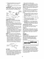
SAE
VISCOSITY
GRADES
/
-20
5/8" Bolt__
AND TERMINALS
Corrosion
and dirt on the battery and
terminals can cause the battery to "leak"
power.
1. Disconnect
BLACK battery cable first
then RED battery cable and remove
battery from tractor.
2. Rinse the battery with plain water and
dry.
3. Clean terminals and battery cable ends
with wire brush until bright.
4. Coat terminals with grease or petroleum jelly.
5. Reinstall battery (See "REPLACING
BATTERY" in the SERVICE AND AD-
Mandrel
Assembly
BI
BATTERY
-30
__,
0
-20
TEMPERATURE
30
-10
RANGE
32
0
ANTICIPATED
40
60
10
BEFORE
80
20
NEXT
100
30
OIL
40
CHANGE
ol vi_ ch_trtl
NOTE: Although multi-viscosity
oils
(5W30, 10W30 etc.)improve
starting in
cold weather, they will result in increased
oil consumption
when used above 32°E
Check your engine oil level more frequently to avoid possible engine damage from
running low on oil.
de
BATTERY
Your tractor has a battery charging system
which is sufficient for normal use. However, periodic charging of the battery with
an automotive
charger will extend its life.
• Keep battery and terminals clean.
• Keep battery bolts tight.
19
÷
Change the oil after every 25
eration or at least once a year
tor is not used for 25 hours in
Check the crankcase
oil level
CLEAN
hours of opif the tracone year.
before
Air screen must be kept free of dirt and
chaff to prevent engine damage from
overheating.
Clean with a wire brush or
compressed
air to remove dirt and stubborn dried gum fibers.
starting the engine and after each eight
(8) hours of operation.
Tighten oil fill
cap/dipstick
securely each time you check
the oil level.
Check
the crankcase
AIR FILTER
Your engine will not run properly using
a dirty air filter. Service air cleaner more
often under dusty conditions.
See Engine
Manual.
oil level before start-
ing the engine and after each eight (8)
hours of operation.
Tighten oil fill cap/
dipstick securely each time you check the
oil level.
TO CHANGE
ENGINE
MUFFLER
Inspect and replace corroded muffler and
spark arrester (if equipped)
as it could create a fire hazard and/or damage.
SPARK PLUG(S)
Replace spark plug(s) at the beginning
of each mowing season or after every
100 hours of operation, whichever occurs
first. Spark plug type and gap setting are
shown in "PRODUCT
SPECIFICATIONS"
section of this manual.
OIL
Determine temperature
range expected
before oil change.
All oil must meet API
service classification
SG-SL.
• Be sure tractor is on level surface.
• Oil will drain more freely when warm.
• Catch oil in a suitable container.
1.
2.
AIR SCREEN
Remove oil fill cap/dipstick.
Be careful
not to allow dirt to enter the engine
when changing oil.
Remove yellow cap from end of drain
valve and install the drain tube onto the
fitting.
IN-LINE
FUEL
FILTER
The fuel filter should be replaced once
each season.
If fuel filter becomes
clogged, obstructing
fuel flow to carburetor, replacement
is required.
1. With engine cool, remove filter and
plug fuel line sections.
2. Place new fuel filter in position in fuel
line with arrow pointing towards carburetor.
3. Be sure there are no fuel line leaks and
clamps are properly positioned.
4. Immediately
wipe up any spilled gasoline.
Oil Drain Valve
lDrain
Tube
3.
Unlock drain valve by pushing inward
slightly and turning counterclockwise.
4. To open, pull out on the drain valve.
5. After oil has drained completely,
close
and lock the drain valve by pushing
inward and turning clockwise
until the
pin is in the locked position as shown.
6. Remove the drain tube and replace the
cap onto the end of the drain valve.
7. Refill engine with oil through oil fill dipstick tube. Pour slowly. Do not overfill.
For approximate
capacity see "PRODUCT SPECIFICATIONS"
section of this
manual.
8.
Clamp _Clamp
Fuel Filter_
CLEANING
• Clean engine, battery, seat, finish, etc.
of all foreign matter.
• Keep finished surfaces and wheels free
of all gasoline, oil, etc.
• Protect painted surfaces with automotive type wax.
We do not recommend
using a garden
hose or pressure washer to clean your
tractor unless the engine and transmission are covered to keep water out. Water
in engine or transmission
will shorten the
useful life of your tractor. Use compressed
air or a leaf blower to remove grass,
leaves and trash from tractor and mower.
Use gauge on oil fill cap/dipstick
for
checking level. For accurate reading,
tighten dipstick cap securely onto the
tube before removing dipstick.
Keep oil
at "FULl" line on dipstick. Tighten cap
onto the tube securely when finished.
20
_b
ARNING:
TO AVOID SERIOUS
VICE OR ADJUSTMENTS:
1.
2.
3.
4.
5.
6.
INJURY,
Raise lift lever to raise suspension
arms. Slide mower out from under tractor.
IMPORTANT:
If an attachment
other than
the mower deck is to be mounted on the
from the
right side of tractor.
1. Place attachment
clutch in "DISENGAGED" position.
2. Move attachment
lift lever forward to
lower mower to its lowest position.
3. Roll belt off engine pulley.
4. Remove small retainer spring, and
remove clutch spring off pulley bolt.
5. Remove large retainer spring, slide
collar off and push housing guide out
of bracket.
8.
ANY SER-
9.
TO REMOVE MOWER
Mower will be easier to remove
7.
PERFORMING
Depress clutch/brake
pedal fully and set parking brake.
Place gearshift lever in neutral (N) position.
Place attachment
clutch in "DISENGAGED"
position.
Turn ignition key to "STOP" and remove key.
Make sure the blades and all moving parts have completely
stopped.
Disconnect
spark plug wire from spark plug and place wire where it cannot
come in contact with plug.
TRACTOR
6.
BEFORE
tractor, remove the front links and hook
the clutch spring Into square hole in frame.
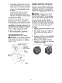
TO INSTALL
1.
Disconnect
anti-sway bar from chassis
bracket by removing retainer spring.
Disconnect
suspension
arms from rear
deck brackets by removing retainer
springs.
Disconnect
front links from deck by
removing retainer springs.
Small Retainer Spring
MOWER
2.
Raise attachment
lift lever to its highest
position.
Slide mower under tractor with deflec-
3.
4.
tor shield to right side of tractor.
Lower lift lever to its lowest position.
Connect front links to mower deck and
5.
secure with retainer springs.
Connect suspension
arms to rear
deck brackets and secure with retainer
springs.
Flat Washer
Clutch
Spring
. _.
. -.,_ ....
.-
i¢
- _ ¢¢¢_
"_'&'Square
Arms
Hole
Engine
Pulley
Front Link
Retainer
Spring
\
Anti-Sway
Bar
Springs
(Both Sides)
Deflector
Housing
Guide
ge Retainer
Spring
Bracket
21
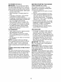
To obtain the best cutting results, the
mower housing should be adjusted so
that the front is approximately 1/8" to 1/2"
lower than the rear when the mower is in
its highest position.
Check adjustment on right side of tractor. Measure distance "D" directly in front
and behind the mandrel at bottom edge of
mower housing as shown.
• Before making any necessary adjustments, check that both front links are
equal in length.
• If links are not equal in length, adjust
one link to same length as other link.
• To lower front of mower loosen nut "E"
on both front links an equal number of
turns.
• When distance "D" is 1/8" to 1/2"
lower at front than rear, tighten nuts "F"
against trunnion on both front links.
• To raise front of mower, loosen nut "F"
from trunnion on both front links. Tighten
nut "E" on both front links an equal number of turns. The two front links must
remain equal in length.
• When distance "D" is 1/8" to 1/2" lower
at front than rear, tighten nut "F" against
trunnion on both front links.
• Recheck side-to-side adjustment.
6.
Connect anti-sway bar to chassis
bracket and secure with retainer spring.
7. Push clutch cable housing guide into
bracket, slide collar onto guide and
secure with large retainer spring.
8. Place flat washer and clutch spring on
idler pulley bolt and secure with small
retainer spring.
9. Install belt onto engine pulley.
TO LEVEL
MOWER
HOUSING
Adjust the mower while tractor is parked
on level ground or driveway.
Make sure
tires are properly inflated (See "PRODUCT SPECIFICATIONS"
section of this
manual).
If tires are over or underinflated,
you will not properly adjust your mower.
SIDE-TO-SIDE
ADJUSTMENT
• Raise mower to its highest position.
• At the midpoint of both sides of mower,
measure height from bottom edge of
mower to ground.
Distance "A" on both
sides of mower should be the same or
within 1/4" of each other.
• If adjustment
is necessary, make adjustment on one side of mower only.
• To raise one side of mower, tighten lift
link adjustment
nut on that side.
• To lower one side of mower, loosen lift
link adjustment
nut on that side.
NOTE:
Each full turn of adjustment
nut
will change mower height about 1/8".
• Recheck measurements
after adjusting.
Bottom edge of
mower to ground
Oo
],
oo0....
Mandrel
Bottom edge of
mower to ground
Both Front Unks Should beEqual in Length
i-A
- ;[ ............
Nut "F"
Lift Link Adjustment
Nut
Trunnion
FRONT-TO-BACK ADJUSTMENT
IMPORTANT: Deck must be level side-to
side. If the following front-to-back adjustment is necessary, be sure to adjust both
front links equally so mower will stay level
side-to-side.
Front Links
22
J_
TO REPLACE
BELT
MOWER
BLADE
DRIVE
TO CHECK
1.
2.
3.
-
Remove mower from tractor (See "TO
REMOVE MOWER" in this section of
manual).
Work belt off both mandrel pulleys
idler pulleys.
Pull belt away from mower.
BELT INSTALLATION
1.
2.
3.
BRAKE
Your tractor is equipped with an adjustable
brake system which is mounted on the
right side of the transaxle.
If tractor requires more than five (5) feet to
stop at highest speed in highest gear on a
level, dry concrete or paved surface, then
brake must be checked and adjusted.
The mower blade drive belt may be replaced without tools. Park the tractor on
level surface.
Engage parking brake.
BELT REMOVAL
AND ADJUST
TO CHECK
BRAKE
1.
Park tractor on a level, dry concrete or
paved surface, depress clutch/brake
pedal all the way down and engage
parking brake.
2. Place gear shift lever in neutral (N)
position.
The rear wheels must lock and skid when
and
-
Work belt around both mandrel pulleys
and idler pulleys
Make sure belt is in all pulley grooves
and inside all belt guides.
Install mower (See "To Install Mower" in
this section of this manual).
you try to manually push the tractor forward. If the rear wheels rotate, the brake
needs to be adjusted or the pads need to
be replaced.
Idler
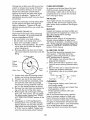
TO ADJUST
Mandrel
Pulle'
BRAKE
1.
Depress clutch/brake
pedal all the way
down and engage parking brake.
2. Measure distance between brake operating arm and nut "A" on brake rod.
3. If distance is other than 1-1/2", loosen
jam nut and turn nut "A" until distance
becomes 1-1/2". Retighten jam nut
against nut "A".
4. Road test tractor for proper stopping
distance as stated above. Readjust
if necessary.
If stopping distance is
still greater than five (5) feet in highest
gear, further maintenance
is necessary. Contact an authorized
service
center/department.
Mandrel
Pulley
With parking
brake "Engaged"
Operating Arm
23
TO REPLACE
MOTION
DRIVE
BELT
TRANSAXLE
GEAR
TRAL ADJUSTMENT
Park the tractor on level surface.
Engage
parking brake. For assistance,
there is a
belt installation
guide decal on bottom side
of left footrest.
BELT REMOVAL
-
Remove mower (See "TO REMOVE
MOWER" in this section of manual).
NOTE: Observe entire motion drive belt
5.
rear of tractor.
Remove belt upwards from transaxle
pulley by deflecting belt keepers.
Remove belt from center span keeper
and pull belt away from tractor.
BELT INSTALLATION
NEU-
freely, the transaxle is in neutral.
2. Loosen adjustment
bolt in front of the
right rear wheel.
3. Position the gear shift lever in the neutral (N) position.
4. Tighten adjustment
bolt securely.
NOTE:
If additional
clearance is needed
and position of all belt guides and keepers.
2. Remove belt from stationary
idler and
clutching idler.
3. Remove belt downward
from around
engine pulley.
Pull belt slack toward
LEVER
The transaxle should be in neutral when
the gear shift lever is in neutral (N) (lock
gate) position. The adjustment
is preset
at the factory; however, if adjustment
is
needed, proceed as follows:
1. Make sure transaxle is in neutral (N).
NOTE: When the tractor rear wheels move
1.
4.
SHIFT
to get to adjustment
bolt, move mower
deck height to the lowest position.
Gearshift Lever
-
1.
Carefully work new belt down between
transaxle belt keepers and onto the
input pulley.
2. Slide belt into the center span keeper.
3. Pull belt toward front of tractor and roll
around the top groove of engine pulley.
4. Install belt through stationary
idler and
clutching idler.
5. Make sure belt is in all pulley grooves
and inside all belt guides and keepers.
6. Install mower (See "TO INSTALL
MOWER" in this section of manual).
Adjustment
TO ADJUST
MENT
Engine
Pulle'
Clutching
Idler
If steering
horizontal
positioned
ing wheel
horizontal.
Stationary
Idler
FRONT
STEERING
Bolt
WHEEL
ALIGN-
wheel crossbars are not
(left to right) when wheels are
straight forward, remove steerand reassemble
with crossbars
Tighten securely.
WHEEL
The front wheel
Center
Span
Keeper ...... "
Neutral
Lock
Gate
TOE-IN/CAMBER
toe-in
and camber
are not
adjustable
on your tractor. If damage has
occurred to affect the front wheel toe-in or
camber, contact your nearest
service center/department.
Transaxle
Pulley
0081"
24
authorized
TO REMOVE
WHEEL
FOR REPAIRS
TO REMOVE
ORDER -
1.
2.
Block up axle securely.
Remove axle cover, retaining ring and
washers to allow wheel removal (rear
wheels have a square key - Do not
lose).
3. Repair tire and reassemble.
NOTE: On rear wheels only: align
grooves in rear wheel hub and axle. Insert
square key.
4. Replace washers and snap retaining
ring securely in axle groove.
5. Replace axle cover.
NOTE: To seal tire punctures and prevent
flat tires due to slow leaks, tire sealant
may be purchased
from your local parts
dealer. Tire sealant also prevents tire dry
rot and corrosion.
1.
2.
BLACK cable first from chassis and
then from the fully charged battery.
RED cable last from both batteries.
02614
Weak or Dead
Battery
REPLACING
Fully Charged
Battery
BATTERY
_WARNING:
Do not short battery
terminals by allowing a wrench or any
other object to contact both terminals
at
the same time. Before connecting
battery,
remove metal bracelets, wristwatch
bands,
rings, etc.
Positive terminal must be connected
Retaining
Rinc
Axle
Cover
first to prevent sparking from accidental
grounding.
1. Lift seat pan to raised position.
2. Disconnect
BLACK battery cable first
then RED battery cable and carefully
remove battery from tractor.
3. Install new battery with terminals in
same position as old battery.
4. First connect RED battery cable to
positive (+) terminal with hex bolt and
keps nut as shown. Tighten securely.
Slide terminal cover over terminal
5. Connect BLACK grounding
cable to
negative (-) terminal with remaining
hex bolt and keps nut. Tighten securely.
I
Square Key
(Rear Wheel Only)
ENGINE
REVERSE
I II I
Washers
TO START
TERY
CABLES,
WITH
A WEAK
BAT-
,_WARNING:
Lead-acid batteries generate explosive gases. Keep sparks, flame
and smoking materials away from batteries. Always wear eye protection when
around batteries.
If your battery is too weak to start the
engine, it should be recharged.
(See "BATTERY" in the MAINTENANCE
section of
this manual).
If "jumper cables" are used for emergency
starting, follow this procedure:
IMPORTANT:
Your tractor is equipped
with a 12 volt system. The other vehicle
must also be a 12 volt system. Do not use
your tractor battery to start other vehicles.
TO ATTACH
JUMPER
1.
Connect
one end of the RED cable
CABLES
2.
to the POSITIVE (+) terminal of each
battery(A-B),
taking care not to short
against tractor chassis.
Connect one end of the BLACK cable
Seat
-
Terminal
Nut
Hex
Bolt
to the NEGATIVE (-) terminal (C) of
fully charged battery.
3. Connect the other end of the BLACK
cable (D) to good chassis ground,
away from fuel tank and battery.
Ke
(Red)
Cable
25
Negative
(Black) Cable
TO REPLACE
1.
2.
HEADLIGHT
Raise hood.
Pull bulb holder
BULB
TO REMOVE
SEMBLY
out of the hole in the
cause
running,
AND
GRILL
AS-
1. Raise hood.
2. Unsnap headlight wire connector.
3. Stand in front of tractor. Grasp hood at
sides, tilt toward engine and lift off of
tractor.
backside of the grill.
3. Replace bulb in holder and push bulb
holder securely back into the hole in
the backside of the grill.
4. Close hood.
INTERLOCKS
AND RELAYS
Loose or damaged wiring may
your tractor to run poorly, stop
prevent it from starting.
• Check wiring. See electrical
diagram in the Repair Parts
TO REPLACE
FUSE
HOOD
4.
When replacing hood, be sure to reconnect the headlight wire connector.
or
wiring
section.
Headlight
Wire
Connector
Replace with 20 amp automotive-type
plug-in fuse. The fuse holder is located
behind the dash.
ENGINE
TO ADJUST
CABLE
THROTTLE
CONTROL
The throttle control has been preset at the
factory and adjustment
should not be necessary. Check adjustment
as described
below before loosening cable. If adjustment is necessary, see engine manual
TO ADJUST
CARBURETOR
The carburetor
has been preset at the
factory and adjustment
should not be necessary. However, minor adjustment
may
be required to compensate
for differences
in fuel, temperature,
altitude or load. If
the carburetor
does need adjustment,
see
engine manual.
26
blended fuels (called gasohol or using
ethanol or methanol)
can attract moisture
which leads to separation
and formation of
acids during storage. Acidic gas can damage the fuel system of an engine while in
storage.
• Empty the fuel tank by starting the engine and letting it run until the fuel lines
and carburetor
are empty.
• Never use engine or carburetor
cleaner
products in the fuel tank or permanent
damage may occur.
• Use fresh fuel next season.
Immediately
prepare your tractor for storage at the end of the season or if the tractor will not be used for 30 days or more.
WARNING:
Never store the tractor
with gasoline in the tank inside a building
where fumes may reach an open flame
or spark. Allow the engine to cool before
storing in any enclosure.
TRACTOR
Remove
mower
from tractor
for winter
storage.
When mower is to be stored for a
period of time, clean it thoroughly,
remove
all dirt, grease, leaves, etc. Store in a
clean, dry area.
1. Clean entire tractor (See "CLEANING"
in the Maintenance
section of this
manual).
2. Inspect and replace belts, if necessary
(See belt replacement
instructions
in
the Service and Adjustments
section of
this manual).
3. Lubricate as shown in the Maintenance
section of this manual.
4. Be sure that all nuts, bolts and screws
are securely fastened.
Inspect moving
parts for damage, breakage and wear.
Replace if necessary.
5. Touch up all rusted or chipped paint
surfaces; sand lightly before painting.
NOTE: Fuel stabilizer is an acceptable
alternative
in minimizing
the formation of
fuel gum deposits during storage. Add
stabilizer to gasoline in fuel tank or storage container.
Always follow the mix ratio
found on stabilizer container.
Run engine
at least 10 minutes after adding stabilizer
to allow the stabilizer to reach the carburetor.
Do not empty the gas tank and
carburetor
if using fuel stabilizer.
ENGINE OIL
Drain oil (with engine warm) and replace
with clean engine oil. (See "ENGINE" in
the Maintenance
section of this manual).
CYLINDER(S)
1.
2.
BATTERY
3.
• Fully charge the battery for storage.
• After a period of time in storage, battery
may require recharging.
• To help prevent corrosion
and power
leakage during long periods of storage,
battery cables should be disconnected
and battery cleaned thoroughly
(see "TO
CLEAN BATTERY AND TERMINALS"
in
4.
Remove spark plug(s).
Pour one ounce of oil through spark
plug hole(s)into
cylinder(s).
Turn ignition key to start position for a
few seconds to distribute oil.
Replace with new spark plug(s).
OTHER
• Do not store gasoline
to another.
from one season
• Replace your gasoline can if your can
starts to rust. Rust and/or dirt in your
gasoline will cause problems.
• If possible, store your tractor indoors
and cover it to give protection from dust
and dirt.
the Maintenance
section of this manual).
• After cleaning, leave cables disconnected and place cables where they
cannot come in contact with battery
terminals.
• Cover your tractor with a suitable protective cover that does not retain mois-
• If battery is removed from tractor for
storage, do not store battery directly on
concrete or damp surfaces.
ture. Do not use plastic.
Plastic cannot
breathe which allows condensation
to
form and will cause your tractor to rust.
IMPORTANT:
Never cover tractor while
ENGINE
FUEL SYSTEM
engine
IMPORTANT:
It is important to prevent
gum deposits from forming in essential
fuel system parts such as carburetor, fuel
hose, or tank during storage. Also, alcohol
27
and exhaust
areas are still warm.
TROUBLESHOOTING
PROBLEM
CAUSE
Will not start
Hard to start
Engine will not
turn over
Out of fuel.
2.
3.
Engine not "CHOKED"
properly.
Engine flooded.
4.
5.
6.
7
Bad spark plug.
Dirty air filter.
Dirty fuel filter.
Water in fuel.
8.
9.
Loose or damaged wiring.
Carburetor
out of adjustment.
10. Contact a qualified
center/department.
1.
2.
3.
4.
5.
Dirty air filter.
Bad spark plug.
Weak or dead battery.
Dirty fuel filter.
Stale or dirty fuel.
6.
7.
Loose or damaged wiring.
Carburetor
out of adjustment.
1. Clean/replace
air filter.
2. Replace spark plug.
3. Recharge or replace battery.
4. Replace fuel filter.
5. Empty fuel tank and refill tank
with fresh, clean gasoline.
6. Check all wiring.
7. See "To Adjust Carburetor"
in
Service and Adjustments
section.
service
8. Engine valves out of
adjustment.
8.
Contact a qualified
service center/department.
1.
1.
Depress
2.
Disengage
clutch.
3.
4.
5.
6.
7.
8.
Recharge or replace battery.
Replace fuse.
Clean battery terminals.
Check all wiring.
Check/replace
ignition switch.
Check/replace
solenoid or
starter.
Faulty operator presence
switch(es).
9.
Contact a qualified
center/department.
1.
2.
3.
4.
Weak or dead battery.
Corroded battery terminals.
Loose or damaged wiring.
Faulty solenoid or starter.
1. Recharge or replace battery.
2. Clean battery terminals.
3. Check all wiring.
4. Check/replace
solenoid or
starter.
1.
Cutting
fast.
2.
Throttle
1. Raise cutting height/reduce
speed.
2. Adjust throttle control.
g.
Loss of power
1. Fill fuel tank.
2. See "TO START ENGINE" in
Operation section.
3. Wait several minutes before
attempting
to start.
4. Replace spark plug.
5. Clean/replace
air filter.
6. Replace fuel filter.
7. Empty fuel tank and carburetor, refill tank with fresh gas
oline and replace fuel filter.
8. Check all wiring.
9. See "To Adjust Carburetor"
in Service and Adjustments
section.
10. Engine valves out of
adjustment.
3.
4.
5.
6.
7.
8.
but
CORRECTION
1.
2.
Engine clicks
will not start
CHART
Clutch/brake
pedal not
depressed.
Attachment
clutch is
engaged.
Weak or dead battery.
Blown fuse.
Corroded battery terminals.
Loose or damaged wiring.
Faulty ignition switch.
Faulty solenoid or starter.
too much grass/too
in "CHOKE"
28
position.
clutch/brake
pedal.
attachment
service
TROUBLESHOOTING
PROBLEM
Loss of power
(continued)
CHART
CAUSE
3.
CORRECTION
Build-up of grass, leaves and
trash under mower.
3.
4.
5.
6.
Dirty air filter.
Low oil level/dirty oil.
Faulty spark plug.
4.
5.
6.
7.
8.
Dirty fuel filter.
Stale or dirty fuel.
7.
8.
9.
Water
in fuel.
9.
plug wire loose.
10.
10. Spark
11.
12.
13.
14.
Dirty engine air screen/fins.
Dirty/clogged
muffler.
Loose or damaged wiring.
Carburetor
out of adjustment
15. Engine valves
adjustment.
Excessive
vibration
Engine dies when
tractor is shifted
into reverse
1. Worn,
out of
11.
12.
13.
14.
bent or loose blade.
Replace
bolt.
Contact a qualified service
center/department.
Tighten loose part(s).
Replace damaged parts.
2.
3.
Loose/damaged
3.
Reverse operation system
(ROS) is not "ON" while
mower or other attachment
service
1.
Bent blade mandrel.
part(s).
of mower
housing.
Clean/replace
air filter.
Check oil level/change
oil.
Clean and regap or change
spark plug.
Replace fuel filter.
Empty fuel tank and refill tank
with fresh, clean gasoline.
Empty fuel tank and carburetor, refill tank with fresh gasoline and replace fuel filter.
Connect and tighten spark
plug wire.
Clean engine air screen/fins.
Clean/replace
muffler.
Check all wiring.
See "To Adjust Carburetor"
in
Service and Adjustments
section.
15. Contact a qualified
center/department.
2.
.
Clean underside
blade. Tighten
blade
1. Turn ignition key to
ROS "ON" position.
See Operation section.
is engaged.
Engine continues
to run when operator leaves seat
with attachment
clutch
1.
Faulty operator-safety
presence
control system.
.
Check wiring,
connections.
switches
and
If not contact a
qualified service
partment.
center/de-
engaged
Poor cut - uneven
.
2.
3.
4.
5.
Worn,
bent or loose blade.
Mower deck not level.
Buildup of grass, leaves,
trash under mower.
Bent blade mandrel.
and
Clogged mower deck vent
holes from buildup of grass,
leaves, and trash around
mandrels.
29
1.
2.
3.
4.
5.
Replace blade. Tighten
blade bolt.
Level mower deck.
Clean underside of mower
housing.
Contact a qualified service
center/department.
Clean around mandrels to
open vent holes.
TROUBLESHOOTING
CHART
PROBLEM
Mower blades will
not rotate
CORRECTION
CAUSE
1.
Obstruction
mechanism•
1. Remove obstruction•
in clutch
2.
Poor grass
discharge
Worn/damaged
mower drive
belt.
3. Frozen idler pulley•
4. Frozen blade mandrel•
2.
Replace
3.
4.
Replace idler pulley.
Contact a qualified service
center/department.
1. Engine speed too slow.
1.
Place throttle
2. Travel speed
3. Wet grass.
too fast.
2.
3.
4.
5.
Mower deck not level•
Low/uneven
tire air
4.
6.
pressure•
Worn, bent or loose blade.
7.
5.
8.
Buildup of grass, leaves
and trash under mower.
Mower drive belt worn.
9.
Blades
10. Improper
improperly
blades
installed.
used.
11 •Clogged
mower deck vent
holes from buildup of grass,
leaves, and trash around
mandrels.
6.
7.
8.
9.
mower drive belt.
control
in
"FAST" position.
Shift to slower speed.
Allow grass to dry before
mowing.
Level mower deck.
Check tires for proper air
pressure.
Replace/sharpen
blade.
Tighten blade bolt.
Clean underside of mower
housing.
Replace
Reinstall
down.
mower drive belt.
blades sharp edge
10. Replace with blades listed in
this manual.
11. Clean around mandrels to
open vent holes.
Headlight(s)
not
working
(if so equipped)
1.
2.
3.
4.
5.
Light switch is "OFF".
Bulb(s) or lamp(s) burned out
Faulty light switch.
Loose or damaged wiring.
Blown fuse.
1. Turn light switch "ON".
2. Replace bulb(s) or lamp(s).
3. Check/replace
light switch.
4. Check wiring and connections
5. Replace fuse.
Battery will not
charge
1.
2.
Bad battery cell(s).
Poor cable connections.
1.
2.
Replace battery.
Check/clean
all connections.
3.
Faulty regulator
(if so equipped).
Faulty alternator.
3.
Replace
regulator.
4.
Replace
alternator.
4.
Engine "backfires'
when turning
engine "OFF"
•
Engine throttle control not
set between half and full
speed (fast) position
stopping engine•
30
before
•
Move throttle
control
between half and full speed
(fast) position before
stopping engine•
TRACTOR
SCHEMATIC
- -MODEL
NUMBER
425014X92E
(96014000100)
BATTERY
E
olllll,
SOLENOID
A_METEn
STARTER
FUSE
(OPTIONAL)
rO
i
:0_
i
i
i
i
(PEDAL
UP)
CLUTCH/BRAKE
BLAOK
BLACK
GRAY
REVERSE
r
8LACK
ff
SWITCH
SHORTING
I
i
-
I'
.....
IGNITION
UNIT
BLUE
CONNECTOR
NOT IN REVERSE
_SPARKPLUG_
J
- (2 PLUGS
ON TWIN CYL. ENGINES)
HOUR
METER
B_,CK
(OPTIONAL)
BLUE
CHARGING
SYSTEM OUTPUT
3 AMP DC @ 3600 RPM
RFD
SOLENOID
FUEL
SHUT-OFF
I _
I
r
LIGHT
i
SWITCH
_1
____
5AMPAC@3600RPM DIODE
LIGHTING
28 VOLTS AC MIN @ 3600 RPM
(CHARGING
SYS]:EM DISCONNECTED)
SYSTFM
OUTPUT
i
ALTERNATOR
RPM
NOTE
SWITCH
POSITION CIRCUIT
OFF
"MAKE"
M+G+A1
RUN/OVERRID[ B+A1
RUN
B+A1
START
3 + S + A1
L+A2
(LIGHTS
OFF)
BROWN
O__
IGNITION
i
I
14 VOLTS AC MIN. @ 3600
[
'_l
BLACK
HEADLIGHTS
YOUR TRACTOR IS
EQUIPPED WITH A SPECIAL
ALTERNATOR
SYSTEM.
THE LIGHTS ARE NOT
CONNECTED
TO THE
BATTERY, BUT HAVE THEIR
OWN ELECTRICAL
SOURCE.
BECAUSE OF THIS, THE
BRIGHTNESS
OF THE LIGHTS
WILL CHANGE WITH ENGINE
SPEED. AT IDLE THE LIGHTS
WILL DIM. AS THE ENGINE IS
SPEEDED UP, THE LIGHTS
WILL BECOME THEIR BRIGHTEST.
02836
31
•
NON-REMOVABLE
CONNECTIONS
©
REMOVABLE
CONNECTIONS
WIRING INSULATED CLIPS
NOTE: IF WIRING INSULATED CLIPS
WERE REMOVED FOR SERVICING OF
UNIT, THEY SHOULD BE REPLACED
TO PROPERLY SECURE YOUR WIRING.
TRACTOR - - MODEL NUMBER
425014X92E
(96014000100)
ELECTRICAL
I
I
I
42
I
I
I
i
i
I
I
I
f
26
i
\
16
34
\
\
\
\
i
-
- --T
/
I
i
16_
r ....
i
i
\
\
i
/
!
\i
48
52
28
I
I
I
I
32
/
TRACTOR - - MODEL NUMBER 425014X92E
ELECTRICAL
(96014000100)
KEY
PART
NO.
NO.
DESCRIPTION
1
2
163465
74760412
Battery
Bolt Hex Hd 1/4-20
8
16
21
22
24
25
26
27
28
29
176689
176138
175688
4152J
4799J
146147
175158
73510400
4207J
192749
Box Battery Fender
Switch, interlock
Harness Asm Light W/4152j
Bulb Light #1156
Cable Battery 6 Ga. 11" red
Cable Battery 6 Ga. w/16 wire red
Fuse 20 AMP
Nut, Keps Hex 1/4-20 unc
Cable Ground 6 Ga. 12" black
Switch Seat
30
33
34
40
41
42
43
48
52
90
92
93
94
193350
140401
110712X
193374
71110408
131563
192507
140844
141940
180449
193465
192540
191834
Switch Ign
Key Ign Molded
Switch Light
Harness Ign
Bolt BIk. Fin Hex 1/4-20 unc x 1/2
Cover Terminal Red
Solenoid
Adapter Ammeter
Protection Wire Loop
Cover Battery Terminal
Harness Pigtail Reverse Switch
Screw Plastic 10-14 x 2.0
Module Reverse ROS
NOTE:
All component
dimensions
1 inch = 25.4 mm
33
unc x 314
give in U.S.
inches
TRACTOR
- - MODEL
CHASSIS AND ENCLOSURES
NUMBER
425014X92E
(96014000100)
29
212
28
39
30
18
\
278
25
26
207
26
209
209
33
10
208
34
26
38_
34
4
Chassis-AFpha
Stlt 3
TRACTOR
- - MODEL
CHASSIS AND ENCLOSURES
NUMBER
425014X92E
(96014000100)
KEY
NO.
PART
NO.
1
2
5
9
10
11
13
14
17
18
24
25
26
28
174619
176554
155272
193510X010
72140608
174996
172105X010
17490608
187559X505
184921
74780616
19131312
73800600
187598
29
30
187567X599
192526X505
Chassis Stamping
Drawbar
Bumper Hood/Dash
Dash
Bolt, Carriage
3/8-16 x 1
Panel, Dash, L.H.
Panel, Dash, R.H.
Screw Thdrol 3/8-16 x 1/2
Hood Assembly
Bumper Hood Large 1.75
Bolt Fin Hex 3/8-16 unc x 1 Gr. 5
Washer 13132 x 13/16 x 12 Ga.
Nut
Grille Lens Asm Laser
(includes
Key Nos. 29 and 212)
Lens
Fender
31
33
34
35
37
38
39
64
136619
179716X505
179717X505
72110606
17490508
175710
187568
154798
Bracket, Fender Support
Footrest LH
Footrest RH
Bolt Rdhd Sht Sqnk 3/8-16 x 3/4
ScrewThdrol
5t16-18 x l/2Tyt
Bracket Asm. Pivot Mower Rear
Bracket Pivot
Dash Lower
114
115
142
145
206
207
208
209
158112
17060620
175702
156524
170165
17670508
17670608
17000612
Keeper Belt Rear LH
Screw 3t8-16 x 1-1/4
Plate Reinforcement
Rod Pivot Chassis/Hood
Bolt Shoulder 5/16 -18 TT
Screw 5t16-18 x 1/2
ScrewThdrol
3/8-16 x 1/2
Screw Hex Wsh Thdr 3t8-16
211
212
145212
187569
Nut Hex Flange Lock
Insert Lens Reflective
278
-- -
191611
5479J
187801
Screw 10 x 3/4 Single
Plug, Button
Plug Dome Plastic
NOTE:
DESCRIPTION
x 3/4
Head-Hex
All component dimensions given in U.S. inches
1 inch = 25.4 mm
35
TRACTOR
GROUND DRIVE
- - MODEL
NUMBER
425014X92E
(96014000100)
26
27
drive-fender.stlt
36
46
TRACTOR
GROUND DRIVE
KEY
PART
NO.
NO.
- - MODEL
NUMBER
DESCRIPTION
Peerless
206-544C
425014X92E
KEY
PART
NO.
NO.
DESCRIPTION
Cover, Pedal
Pulley, Engine
Bolt Hex 7/16-20
Washer Lock
1
Transaxle
62
8883R
2
3
4
5
6
8
10
11
13
14
15
16
18
19
21
22
24
25
26
27
146682
123666X
12000028
121520X
17060512
192706
76020416
105701X
74550412
10040400
74490544
73800500
74780616
73800600
106933X
130804
73350600
106888X
19131316
76020412
(Order parts from transaxle
manufacturer)
Spring Brake Return
Pulley Transaxle
Ring Retainer
Strap Torque 30 Degrees
Screw 5/16-18 x 3/4
Rod Shift Fender Adjust
Pin Cotter 1/8 x 1 CAD
Washer Plate Shift
Bolt 1/4-28unf Gr. 8 W/Patch
Washer Lock Hvy Helical
Bolt Hex FLGHD 5/16-18 Gr. 5
Nut Lock Hex W/Ins 5/16-18 UNC
Bolt Fin Hex 3/8-16 UNC x 1 Gr 5
Nut Lock Hex W/Ins 3/8-16 UNC
Knob
Rod, Brake
Nut, Hex Jam 3/8-16 uric
Spring, Brake Rod
Washer 13/32 x 13/16 x 16 Ga.
Pin Cotter 1/8 x 3/4 CAD.
63
64
65
66
69
70
74
75
76
77
78
79
80
81
82
83
84
85
89
96
112
113
175410
173937
10040700
154778
142432
134683
137057
121749X
12000001
123583X
121748X
2228M
145090
165594
165711
19171216
166231
150360
192054X428
4497H
19091210
127285X
28
29
30
32
34
35
36
37
38
39
175765
71673
169592
74760512
175578
120183X
19211616
1572H
179114
72110622
Rod, Parking Brake
Cap, Parking Brake
Bracket, Transaxle
Bolt Hex Hd 5/16-18 UNC x 3/4
Shaft, Foot Pedal
Bearing, Nylon
Washer
Pin, Roll
Pulley, Composite,
Flat
Bolt RDHD 3/8-16 UNC x 1 Gr. 5
116
120
150
151
156
158
159
161
162
163
72140608
73900600
175456
19133210
166002
165589
183900
72140406
73680400
74780416
41
47
48
49
50
51
175556
127783
154407
123205X
72110612
73680600
Keeper, Belt Idler
Pulley, Idler, V-Groove
Bellcrank, Clutch
Retainer, Belt
Bolt Hex Hd 3/8-16 x 1-1/2
Nut Crownlock
3/8-16 uric
165
166
168
169
170
197
165623
17490510
165492
165580
187414
169613
52
53
55
56
57
59
61
73680500
105710X
105709X
17060620
130801
169691
17120614
Nut, Crownlock
Link, Clutch
Spring, Return,
Screw 3/8-16 x
V-Belt
Keeper, Center
Screw.
3/8-16
198
202
212
169593
72110614
145212
5/16-18
uric
Clutch
1.04
(96014000100)
x 4 x Gr. 5
Keeper Belt Engine Hydro
Screw HexWsh
Hi-Lo 1/4 x 1/2 unc
Keeper Belt Engine
Spacer
Washer
25132 x 1-1/4 x 16 Ga.
E-Ring
Key, Square
Washer
25/32 x 1-5/8 x 16 Ga.
Key Woodruff
Arm Shift
Shaft Asm Cross Tapered
Spring Torsion
Washer
17/32 x 3/4 x 16 Ga.
Link Transaxle
Nut Lock Center 1/4-20
Console, Shift
Retainer Spring 1" Zinc/Cad
Washer 9/32 x 3/4 x 10 Ga.
Strap Torque 90 Degrees
Bolt Rdhd Sqneck
318-16 x 1.25
Nut Lock Fig 318-16
Spacer Retainer
Washer
13/32 x 2 x 10 Ga.
Washer Srrted 51161D x 1.125
Bracket Shift Mount
Hub Tapered Flange Shift Lt
Bolt Rdhd Sqnk 1/4-20 x 3/4 Gr 5
Nut Crownlock
1/4-20 unc
Bolt Hex Fin 1/4-20 uric x 1 Gr 5
Bracket Pivot Lever
Screw 5/16-18 x 5t8
Bolt Shoulder 5/16-18 x .561
Plate Fastening
Keeper Belt TIA
Nyliner
Snap-In 5t8"1D
Washer Nyl
Bolt Carr Sh 3/8-16 x 1-3/4 Gr.5
Nut Hex Fig. Lock
NOTE: All component dimensions given in U.S.
inches 1 inch = 25.4 mm
Span
x .875
37
TRACTOR
- - MODEL
STEERING ASSEMBLY
NUMBER
425014X92E
(96014000100)
J
67
67
J
47
67
\
65
_
3
32
43
15
•
_
.....
4 j
/
/
28
30
steering
pllt
58
38
_
\\
43
g5
8
TRACTOR
- - MODEL
STEERING ASSEMBLY
KEY
NO.
NUMBER
PART
NO.
425014X92E
(96014000100)
DESCRIPTION
1
2
3
4
5
6
7
186780
175131
169840
169839
6266H
121748X
19272016
Steering Wheel
Axle Assembly
Spindle Assembly,
L.H.
Spindle Assembly,
R.H.
Bearing, Race, Thrust, Hardened
Washer
25/32 x 1-518 x 16 Ga.
Washer 27/32 x 1-1/4 x 16 Ga.
8
9
10
11
13
15
17
26
28
29
30
32
34
36
37
38
39
40
12000029
3366R
175121
10040600
136518
145212
190753
126847X
19131416
17000612
76020412
192757
10040500
155099
152927
192916
19113812
73540600
Ring, Klip
Bearing Col. Strg.
Draglink
Washer, Lock
Spacer Brg Axle Front
Nut, Hexflange Lock
Shaft, Steering
Bushing, Link, Drag
Washer
13/32 x 7/8 x 16 Ga.
Screw 3/8-16 x 3/4
Pin
Rod, Tie
Washer Lock Hvy Hlcl Spr. 5t16
Bushing, Steering
Screw
Insert, Steering Wheel
Washer 11132 x 2-3t8
Nut Crownlock
3/8-24
41
42
43
44
46
47
65
67
68
71
82
88
186737
145054x428
121749X
190752
121232X
183226
160367
72110618
169827
175146
169835
175118
Adaptor, Steering Wheel
Boot, Steering Shaft
Washer
25/32 x 1-1/4 x 16 Ga.
Extension Shaft Steering
Cap, Spindle
Fitting Grease
Spacer
Brace Axle
Bolt Rdhd Sqnk 3/8-16 x 2-1/4
Axle, Brace
Steering Asm
Bracket Susp Chassis Front
Bolt Shoulder 7/16-20
91
95
97
175553
188967
74780564
Clip Steering
Washer Hardened
.793 x 1.637 x .060
Bolt 5/16-18 unc x 4 Gr. 5
NOTE:
All component
dimensions
1 inch = 25.4 mm
39
given
in U.S. inches
TRACTOR
- - MODEL
NUMBER
425014X92E
(96014000100)
ENGINE
72
62
/
81
13
4
78_
I
38
14
78
33
37
33
29
OPTIONAL
23
EQUIPMENT
Spark Arrester
engine-bs=lcyF
40
38
TRACTOR
- - MODEL
NUMBER
425014X92E
(96014000100)
ENGINE
KEY
NO.
PART
NO.
1
2
3
170551
17720408
4
13
14
23
25
29
31
32
33
37
38
40
44
45
46
62
72
78
81
137352
165291
148456
169837
167994
137180
187750
140527
123487X
137040
181654
124028X
17670412
17000612
19091416
10010500
71070512
17060620
73510400
NOTE:
DESCRIPTION
Control, Throttle/Choke
Screw, Hex Head, Thread
Engine, Briggs
Model No. 282H07 (Order
Muffler
Gasket
Tube Drain Oil Easy
Shield Brn/Dbr Guard
Clutch Cable Asm.
Cutting
1/4-20
x 1/2
parts from engine
Arrestor, Spark
Tank, Fuel
Cap Assembly,
Fuel, Vented
Clamp, Hose
Line, Fuel
Plug, Drain Oil Easy
Bushing Snap
Screw, Hex Washer Head, Thd., Roll. 1/4-20
Screw Hex Wsh Thdr 3/8-16 x 3/4
Washer
9/32 x 7/8 x 16 Ga.
Washer Split
Screw Hex Head Cap 5/16-18
Screw 3/8-16 x 1-1/4
Nut Keps Hex 1/4-20 unc
All component
dimensions
1 inch = 25.4 mm
41
given
x 3/4
in U.S. inches
manufacturer)
x 3/4
TRACTOR
SEAT ASSEMBLY
- - MODEL NUMBER
425014X92E
(96014000100)
5
11
12
seat_It.knob_9
KEY PART
NO. NO.
1
2
3
4
5
6
7
8
9
10
11
12
188705
180166
71110616
19131610
145006
73800600
124181X
17000616
19131614
180186
166369
174648
DESCRIPTION
Seat
Bracket,
Bolt
Washer
Pivot, Seat
13/32 x 1 x 10 Ga.
Clip, Push-In
Nut
Hinged
Spring, Seat
Screw 318-16 x 1-1/2
Washer
13/32 x 1 x 14 Ga.
Pan, Seat
Knob Seat
Bracket, Switch Mounting
KEY
NO.
PART
NO.
DESCRIPTION
13
14
15
16
17
21
22
24
121248X
72050412
134300
121250X
123976X
171852
73800500
19171912
Bushing, Snap
Bolt, Carriage
1/4-20 x 1-1/2
Spacer, Split .28 x .88
Spring
Locknut, Flange
1/4 Gr. 5
Bolt, Shoulder
5/16-18 unc
Nut
Washer
17/32 x 1-3/16 x 12 Ga.
NOTE: All component dimensions given in U.S.
inches 1 inch = 25.4 mm
42
DECALS
TRACTOR
- - MODEL NUMBER
425014X92E
(96014000100)
lO
20
13
KEY
NO.
PART
NO.
1
2
3
5
7
10
11
13
14
193308
184769
198348
194691
198358
157002
179128
198350
160396
WHEELS
13
DESCRIPTION
Decal
Decal
Decal
Decal
Decal
Decal
Decal
Decal
Decal
Oper. instr.
HP Engine
Hood
Hood Replacement
Hood Side
Fender Danger
Deck "B" 42"
Chassis
V-Belt Schematic
KEY
NO.
PART
NO.
DESCRIPTION
20
-----
145005
138311
179768X428
179769X428
198339
Decal, Battery Dngr/Psn Eng
Decal, Lift Handle
Pad, Footrest LH
Pad, Footrest RH
Owner's Manual
KEY PART
NO. NO.
& TIRES
5,8
4,10
!,9
11
1
2
3
4
59192
65139
106222X
59904
5
6
7
106732X624
278H
9040H
8
9
10
106108X624
138468
7152J
11
104757X428
144334
-=
DESCRIPTION
Valve Cap, Tire
Stem, Valve
Tire, Front
Tube, Front Tire
(Not Provided, Service Item Only)
Rim, Front
Fitting, Grease (Front Wheel Only)
Bearing, Flange (Front Wheel
Only)
Rim, Rear
Tire, Rear
Tube, Rear Tire
(Not Provided, Service Item Only)
Cap, Axle
Sealant, Tire 10 oz.
NOTE: All component dimensions given in U.S.
inches 1 inch = 25.4 mm
43
TRACTOR
LIFT ASSEMBLY
- - MODEL
NUMBER
425014X92E
(96014000100)
7
6
5
13
19
13
18 2O
19
15
32
44
TRACTOR
LIFT ASSEMBLY
- -MODEL
NUMBER
425014X92E
(96014000100)
KEY
NO.
PART
NO.
DESCRIPTION
1
2
3
4
5
6
7
8
11
12
13
15
16
17
159460
159471
105767X
12000002
19211621
120183X
109413X
122365X
139865
139866
4939M
173288
73350800
175689
Lift Lever Inner Wire Assembly
Shaft Assembly,
Lift
Pin, Groove
E-Ring
Washer
21/32 x 1 x21 Ga.
Bearing, Nylon
Grip, Handle
Button, Plunger, Red
Link, Lift, L.H.
Link, Lift, R.H.
Retainer Spring
Link, Front
Nut, Hex, Jam 1/2-13 unc
Trunnion
18
19
20
31
32
73800800
139868
163552
169865
73540600
Locknut, Hex, with Washer
Arm, Suspension,
Rear
Retainer Spring
Bearing, Pvt, Lift
Nut, Crownlock
318-24
Insert
NOTE: All component dimensions given in U.S. inches
1 inch = 25.4 mm
45
1/2-13
unc
TRACTOR
MOWER DECK
- - MODEL NUMBER
425014X92E
(96014000100)
67
31
30
34
21
23
24
25
26
2
\.
28
27
29
18
18
5
6
21
42 deck
man-t-path
3
46
\
TRACTOR
MOWER DECK
KEY
NO.
PART
NO.
1
2
3
4
5
6
8
9
10
165892
72140506
138017
165460
4939M
178024
850857
10030600
140296
11
138971
--
134149
--
139775
13
14
15
16
18
19
20
21
23
24
25
26
27
28
29
30
31
32
33
137645
128774
110485X
174493
72140505
132827
159770
73680500
177563
105304X
123713X
110452X
130968X428
19111016
131491
173984
187690
153535
178342
- - MODEL NUMBER
425014X92E
KEY
NO.
PART
NO.
34
36
72110612
131494
Bracket Assembly, Sway Bar, Front
Bracket Sway Bar 38/42" eck
Retainer Spring
Bar Sway Deck
Bolt, Hex 3/8-24 x 1.25 Gr. 8
Washer, Lock
Washer, Hardened
(The following blades are available)
Blade, 42" Hi-Lift
(For bagging or discharging)
Blade, Mulching Std.
(For mulching mowers only)
Blade, 42" Mulching Premium
(For better wear when mulching)
Shaft Assembly,
Mandrel, Vented
Housing, Mandrel, Vented
Bearing, Ball, Mandrel
Stripper, Mower Deck
Bolt, Carriage
5/16-18 x 5/8
Bolt, Shoulder
Baffle, Vortex
Nut Crownlock 5/16-18 uric
40
44
45
46
48
52
53
54
55
56
59
67
68
142
143
144
145
146
147
148
149
150
73900600
140088
4497H
137729
133944
139888
184907
178515
155046
165723
141043
149846
144959
165890
157109
158634
165888
171977
131335
169022
165898
19091210
Bracket, Deflector
Cap, Sleeve
Spring, Torsion, Deflector
Nut, Push
Shield, Deflector
Washer
11/32 x 5/8 x 16 Ga.
152
158
159
184
185
--
169676
17720408
72140614
19131410
188234
130794
--
171639
DESCRIPTION
Mower Deck Assembly,
Bolt 5/16-18 x 3/4
Rod, Hinge
ScrewThdrol
42"
DOD PT Hex
Washer, Spacer
Pulley, Mandrel
Nut, Toplock, Flanged
(96014000100)
DESCRIPTION
Bolt Carr. Sh. 3/8-16
x 1-1/2 Gr. 5
Pulley, Idler, Flat
Nut Lock Fig. 3/8-16 unc
Guard, Mandrel, LH.
Retainer
Screw, Thd. Roll 1/4-20 x 5/8
Washer, Hardened
Bolt, Shoulder
5/16-18 unc
Arm Assembly,
Pad, Brake
Washer, Hardened
Arm, Idler
Spacer, Retainer
Guard, TUV Idler
Knob Custom Oval
V-Belt
Arm Spring Brake Mower
Bracket Arm Idler 42"
Keeper Belt 42" Clutch Cable
Pulley idler Flat
Bolt Carriage idler
Spring Extension
Spring Return idler
Retainer Spring Yellow Zinc
Washer
9/32 x 3/4 x 10 Ga.
Cable Clutch 42 in
Screw Hex Thd Cut 1/4-20 x 1/2
Bolt Rdhd Sqn 3/8-16 unc x 1-3/4
Washer 13/32 x 7/8 x 10 Ga.
Head Assy. Cable Clutch
Mandrel Assembly
(Includes
housing, shaft and shaft hardware
only-pulley
not included)
Replacement
Mower, Complete
NOTE: All component dimensions given in U.S.inches
1 inch = 25.4 mm
47
48
49
50
SUGGESTED
GUIDE FOR SIGHTING
SLOPES FOR SAFE OPERATION
ONLY RIDE UP AND DOWN HILL,
NOT ACROSS HILL
ol
15 DEGREES MAX.
_
down the face of slopes, never across the face. Do not mow
ARNING:
To avoid
serious
injury,
operate
tractor
and
slopes
greater
than 15
degrees.
Make
turns your
gradually
to up
prevent
tipping or loss of control. Exercise extreme caution when
changing direction on slopes.
ii[i_!!iiHi!!!!i!
...........................................................................................................................................................................................................................................................
[i_i/ii[ii!i!i!!
.....................................................................................................................................................................................................................................................................................
% Fold thispage along dotted lineindicatedabove,
2, Hold page before you so that its left edge is vertically paratlet to a tree
trunk or other upright structure.
3, Sight across the foBd in the direction of hill e!ope you want to meaeure,
4, Compare the angle of the fold with the etope of the hill
This product has been expertly engineered
and carefully manufactured
quality standards.
As with all mechanical
products, some adjustments
replacement
may be necessary
For Parts and Service,
•
contact
during
the life of your unit.
our authorized
distributor:
For replacement
parts, have available the following
a.
Model Number / Manufacturer's
I.D. Number
b.
Description
For Technical
of part.
Assistance:
to rigid
or part
call 1-800-829-5886
call 1-800-849-1297
information: